EP2053294A2 - Boot shrouds for joints in conduits - Google Patents
Boot shrouds for joints in conduits Download PDFInfo
- Publication number
- EP2053294A2 EP2053294A2 EP08166655A EP08166655A EP2053294A2 EP 2053294 A2 EP2053294 A2 EP 2053294A2 EP 08166655 A EP08166655 A EP 08166655A EP 08166655 A EP08166655 A EP 08166655A EP 2053294 A2 EP2053294 A2 EP 2053294A2
- Authority
- EP
- European Patent Office
- Prior art keywords
- joint assembly
- shroud
- boot
- shrouded
- conduit
- Prior art date
- Legal status (The legal status is an assumption and is not a legal conclusion. Google has not performed a legal analysis and makes no representation as to the accuracy of the status listed.)
- Granted
Links
- 238000001514 detection method Methods 0.000 claims abstract description 25
- 239000012530 fluid Substances 0.000 claims description 19
- 238000004891 communication Methods 0.000 claims description 9
- 239000000446 fuel Substances 0.000 description 9
- 230000008878 coupling Effects 0.000 description 5
- 238000010168 coupling process Methods 0.000 description 5
- 238000005859 coupling reaction Methods 0.000 description 5
- 239000000463 material Substances 0.000 description 3
- 238000005516 engineering process Methods 0.000 description 2
- 239000007789 gas Substances 0.000 description 2
- 238000003780 insertion Methods 0.000 description 2
- 230000037431 insertion Effects 0.000 description 2
- 239000007788 liquid Substances 0.000 description 2
- 231100000331 toxic Toxicity 0.000 description 2
- 230000002588 toxic effect Effects 0.000 description 2
- 230000003466 anti-cipated effect Effects 0.000 description 1
- 230000000712 assembly Effects 0.000 description 1
- 238000000429 assembly Methods 0.000 description 1
- 239000002131 composite material Substances 0.000 description 1
- 230000006835 compression Effects 0.000 description 1
- 238000007906 compression Methods 0.000 description 1
- 230000001010 compromised effect Effects 0.000 description 1
- 239000004020 conductor Substances 0.000 description 1
- -1 e.g. Substances 0.000 description 1
- 239000000383 hazardous chemical Substances 0.000 description 1
- 230000008676 import Effects 0.000 description 1
- 239000002184 metal Substances 0.000 description 1
- 229920000642 polymer Polymers 0.000 description 1
- 230000002265 prevention Effects 0.000 description 1
- 239000000523 sample Substances 0.000 description 1
- 238000007789 sealing Methods 0.000 description 1
- 239000003440 toxic substance Substances 0.000 description 1
- 238000013022 venting Methods 0.000 description 1
Images


Classifications
-
- F—MECHANICAL ENGINEERING; LIGHTING; HEATING; WEAPONS; BLASTING
- F16—ENGINEERING ELEMENTS AND UNITS; GENERAL MEASURES FOR PRODUCING AND MAINTAINING EFFECTIVE FUNCTIONING OF MACHINES OR INSTALLATIONS; THERMAL INSULATION IN GENERAL
- F16L—PIPES; JOINTS OR FITTINGS FOR PIPES; SUPPORTS FOR PIPES, CABLES OR PROTECTIVE TUBING; MEANS FOR THERMAL INSULATION IN GENERAL
- F16L39/00—Joints or fittings for double-walled or multi-channel pipes or pipe assemblies
- F16L39/005—Joints or fittings for double-walled or multi-channel pipes or pipe assemblies for concentric pipes
-
- F—MECHANICAL ENGINEERING; LIGHTING; HEATING; WEAPONS; BLASTING
- F16—ENGINEERING ELEMENTS AND UNITS; GENERAL MEASURES FOR PRODUCING AND MAINTAINING EFFECTIVE FUNCTIONING OF MACHINES OR INSTALLATIONS; THERMAL INSULATION IN GENERAL
- F16L—PIPES; JOINTS OR FITTINGS FOR PIPES; SUPPORTS FOR PIPES, CABLES OR PROTECTIVE TUBING; MEANS FOR THERMAL INSULATION IN GENERAL
- F16L25/00—Constructive types of pipe joints not provided for in groups F16L13/00 - F16L23/00 ; Details of pipe joints not otherwise provided for, e.g. electrically conducting or insulating means
- F16L25/01—Constructive types of pipe joints not provided for in groups F16L13/00 - F16L23/00 ; Details of pipe joints not otherwise provided for, e.g. electrically conducting or insulating means specially adapted for realising electrical conduction between the two pipe ends of the joint or between parts thereof
-
- B—PERFORMING OPERATIONS; TRANSPORTING
- B64—AIRCRAFT; AVIATION; COSMONAUTICS
- B64D—EQUIPMENT FOR FITTING IN OR TO AIRCRAFT; FLIGHT SUITS; PARACHUTES; ARRANGEMENTS OR MOUNTING OF POWER PLANTS OR PROPULSION TRANSMISSIONS IN AIRCRAFT
- B64D37/00—Arrangements in connection with fuel supply for power plant
- B64D37/005—Accessories not provided for in the groups B64D37/02 - B64D37/28
-
- B—PERFORMING OPERATIONS; TRANSPORTING
- B64—AIRCRAFT; AVIATION; COSMONAUTICS
- B64D—EQUIPMENT FOR FITTING IN OR TO AIRCRAFT; FLIGHT SUITS; PARACHUTES; ARRANGEMENTS OR MOUNTING OF POWER PLANTS OR PROPULSION TRANSMISSIONS IN AIRCRAFT
- B64D37/00—Arrangements in connection with fuel supply for power plant
- B64D37/32—Safety measures not otherwise provided for, e.g. preventing explosive conditions
-
- F—MECHANICAL ENGINEERING; LIGHTING; HEATING; WEAPONS; BLASTING
- F16—ENGINEERING ELEMENTS AND UNITS; GENERAL MEASURES FOR PRODUCING AND MAINTAINING EFFECTIVE FUNCTIONING OF MACHINES OR INSTALLATIONS; THERMAL INSULATION IN GENERAL
- F16L—PIPES; JOINTS OR FITTINGS FOR PIPES; SUPPORTS FOR PIPES, CABLES OR PROTECTIVE TUBING; MEANS FOR THERMAL INSULATION IN GENERAL
- F16L2201/00—Special arrangements for pipe couplings
- F16L2201/30—Detecting leaks
Definitions
- the embodiments described herein generally relate to conduits carrying a fluid, and more particularly relate to coupling assemblies for coupling together conduits for transfer of fluids.
- fuel transfer conduits may be structured as a "tube within a tube,” often referred to as a “shrouded conduit,” which effectively provides a double-walled conduit for containment of the fuel.
- the fuel flows in the inner tube, or primary fuel conduit, and the annular space between the inner and outer conduits provides a leak detection zone.
- Leak detection at a junction between two conduits is often important, especially when the fluid in the conduits is combustible, highly valuable, or a toxic or hazardous substance. Accordingly, technologies for leak prevention and detection of leaks at a junction between two conduits are important in certain industries and in certain fluid transfer operations.
- An exemplary embodiment provides a shrouded conduit joint assembly that includes a joint assembly and a boot shroud.
- the joint assembly includes a first ferrule having a first seal, and a second ferrule having a second seal.
- a clamp operatively engages the first ferrule and the second ferrule.
- the boot shroud surrounds the joint assembly and is spaced from the joint assembly to create a leak detection space between the joint assembly and the boot shroud.
- FIG. 1 Another exemplary embodiment provides a shrouded conduit joint assembly that includes a joint assembly and a boot shroud.
- the joint assembly has a first ferrule having a circumferential groove comprising a first o-ring seal, a second ferrule having a circumferential groove comprising second o-ring seal, and a clamp operatively engaging the first ferrule and the second ferrule.
- the boot shroud surrounds the joint assembly and is spaced from the joint assembly to create a leak detection space between the joint assembly and the boot shroud.
- a yet further exemplary embodiment provides a shrouded conduit joint assembly that includes a joint assembly and a boot shroud.
- the joint assembly has a first ferrule having a circumferential groove comprising a first o-ring seal, and a second ferrule having a circumferential groove comprising second o-ring seal.
- a seal ring surrounds the first o-ring seal and the second o-ring seal, and a clamp surrounds the seal ring.
- the clamp operatively engages the first ferrule and the second ferrule to couple the first ferrule to the second ferrule.
- the boot shroud is flexible and surrounds the joint assembly and is spaced from the joint assembly to create a leak detection space between the joint assembly and the boot shroud.
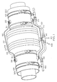
- FIGS. 1 and 2 illustrate an exemplary embodiment of a boot shroud 100 surrounding a conduit joint assembly 500.
- This particular embodiment is intended for use with conduits under "high” internal pressure, where "high” means above about 500 psi, for example, but may of course be used at lower pressures, if desired and appropriate.
- boot shrouds may be fabricated of any of a variety of suitable materials depending upon surrounding environment conditions, temperature and pressure of the fluid in the conduits, nature of the fluid (corrosive, toxic, etc.) and other engineering considerations.
- the boot shroud may be fabricated of a suitable metal, or plastic material (polymer or polymer-composite).
- the boot shroud 100 may be flexible with corrugations 105 to facilitate flexing.
- the illustrated embodiment of a boot shroud 100 has a bellows-like structure well adapted to flexing by compression and/or expansion of the bellows-like corrugations or folds 105.
- the boot shroud 100 extends between a first conduit 200 with a lumen 250 and a second conduit 300 with a lumen 350.
- One or both conduits may be flexible.
- Boot shroud 100 is secured to first conduit 200 by a first circular clamp 110 and is secured to second conduit 300 by a second circular clamp 115.
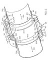
- boot shroud 100 surrounds the conduit joint assembly 500 to form a leak detection space 150 between the boot shroud 100 and the conduit joint assembly 500.
- Boot shroud 100 has a through-hole 125, in this embodiment, for receiving sensors or for providing a drainage point for any leaks from the conduit joint assembly 500 that enter the leak detection space 150.
- the conduit joint assembly is symmetrical in this embodiment and a pair of ferrule adapters 600, one attached to the end 205 of first conduit 200 and another attached to the end 305 of second conduit 300.
- Ferrule adapter 600 is of substantially cylindrical shape with one end 605 configured to engage and end of a conduit, and another end 610 having a circumferentially extending groove 626 to receive an o-ring seal 625.
- ferrule adapters 600 each present an o-ring bearing end to the other for joining together.
- a seal ring 520 covers the adjacent o-ring seals 625 and the seal ring 520 is surrounded by and secured in position by a circular clamp 530. While the circular clamp may not directly touch the o-ring seals 625, the circular clamp is nevertheless considered to operatively engage and secure the o-ring seals to form the conduit joint assembly 500.
- FIG. 1 also depicts ancillary equipment not shown in FIG. 2 , for simplicity.
- a pair of electrical conductors 210 extends from a connection point 215 on the first conduit 200 to a connection point 315 on the second conduit 300.
- the electrical connectors ensure that any electrical potential between the first conduit and the second conduit is minimized and reduces the risk of electrical arcing.
- a joint drainage system 400 includes a three-way connector 410 having a first leg 415 in communication with an internal leak detection space 150 of the boot shroud 100 via through-hole 125 to collect any leaked fluid. Any leaked fluid may then be transported away via conduits 420, 430 for analysis, disposal or other purposes.
- Conduit 420 is secured to first conduit 200 by a circular clamp 425 and conduit 430 is secured to second conduit 300 by circular clamp 435.
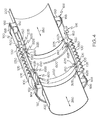
- FIGS 3 and 4 depict another embodiment of a boot-shrouded conduit joint 500.
- the boot shroud 100 is configured and adapted for high pressure service.
- the boot shroud 100 has corrugations 105 on one portion of its surface and an extended, smooth corrugation-free area 160.
- the boot shroud is clamped to the first conduit 200 and to the second conduit 300 proximate its shroud ends 162, 166.
- Shroud end 162 surrounds a shroud-securing ring 180 that surrounds and is affixed to the second conduit 300.
- a circular clamp 164 surrounds the shroud end 162 and clamps it to the shroud-securing ring 180.
- shroud end 166 is secured by clamp 168 and a shroud-securing ring 180.
- the boot shroud surrounds the conduit joint assembly 500 and provides a leak detection space 150 between the boot shroud 100 and the conduit joint assembly 500.
- the leak detection space 150 may have a through-hole 125, as shown, to permit drainage of any leaked fluid and/or insertion of instruments, for example, via a three-way connector 410 (shown in FIG. 4 only).
- the conduit joint assembly 500 is symmetrical in this embodiment as well, and a pair of ferrule adapters 600, one attached to the end 205 of first conduit 200 and another attached to the end 305 of second conduit 300.
- Ferrule adapter 600 is of substantially cylindrical shape with one end 605 configured to engage and end of a conduit, and another end 610 having a groove to receive an o-ring seal 625.
- ferrule adapters 600 each present an o-ring-bearing end 610 to the other for joining together.
- a seal ring 520 covers the adjacent o-ring seals 625 and the seal ring 520 is surrounded by and secured in position by a circular clamp 530. While the circular clamp may not directly touch the o-ring seals 625, the circular clamp is nevertheless considered to operatively engage and secure the o-ring seals to form the conduit joint assembly 500.
- Yet other exemplary embodiments provide shrouded couplings for shrouded or "double-walled" conduits. Such conduits are described for example in commonly assigned US Serial No. 10/998,309 filed November 13, 2004 , which is hereby incorporated by reference.
- a ferrule adapter is required to couple together two shrouded conduits.
- An exemplary embodiment of a ferrule adapter 700 is shown in FIGS. 5 and 6 .
- the ferrule adapter 700 is of substantially cylindrical overall shape and includes an inner cylinder 720 nested within an outer cylinder 710.
- Inner cylinder 720 and outer cylinder 710 are coaxial with an annular space 702 between them.
- the inner cylinder 720 is spaced from the outer cylinder 710 by a series of spokes 735 arrayed such that fluid may flow in spaces between the series of spokes 735.
- the inner cylinder 720 has a groove around its outer circumference, proximate its extremity, configured to receive an o-ring seal 725.
- the outer cylinder 710 likewise has a groove around its circumference, proximate its extremity, configured to receive an o-ring seal 715.
- the inner cylinder 720 also has an opposite extremity 722 adapted to receive an end of a conduit.
- the outer cylinder 710 has an opposite extremity 712 adapted to receive an end of a conduit.
- first shrouded conduit 800 is coupled to a second shrouded conduit 850 utilizing a pair of ferrule adapters 700.
- First shrouded conduit 800 includes a first inner passageway 820 surrounded by a first outer passageway 810 with an annular space 830 between the two passageways.
- second shrouded conduit 850 includes a second inner passageway 860 surrounded by a second outer passageway 840 with an annular space 835 between them.
- the annular spaces 830, 835 may serve as leak detection spaces. Accordingly, it is desirable to isolate these annular spaces 830, 835 from communication with interiors of the inner passageways 820, 860, and to maintain a leak detection space when coupling together the two shrouded conduits 800, 850.
- a boot shroud 100 covers the conduit joint assembly 500 with a leak detection space 150 between the boot shroud 100 and the conduit joint assembly 500. Further, the leak detection space 150 is in fluid communication with annular spaces 830, 835 through spaces 706 between the series of spokes 735 of each of the two ferrule adapters 700. Accordingly, leak detection is not compromised.
- a boot shroud 100 has a through-hole 125 for removal of leaking material, for venting, and/or for insertion of probes or other instruments.
- the conduit joint assembly 500 requires coupling together outer cylinder 710 and inner cylinder 720 of one ferrule adapter 700 to its counterpart on the other ferrule adapter 700. This is achieved by bringing the outer extremities 708 of the inner cylinders 720 of each ferrule adapter 700 into contact, and enclosing opposed o-ring seals 725 within a surrounding inner seal ring 880, which is in turn secured with an inner circular clamp 885. Likewise, o-ring seals 725 of the outer cylinders 720 are enclosed within a surrounding outer seal ring 520 that is secured by a circular clamp 530. This securing of the o-ring seals effectively forms the conduit joint assembly 500.
- a boot shroud 100 surrounds the conduit joint assembly 500, with a leak detection space between them, as explained above.
- the shroud in this example is sealed to the shrouded conduits 800, 850 with a pair of circular clamps 110 that seal outer ends of the boot shroud 100 to the outer surface of the outer passageways 810, 840, as illustrated.
- the primary distinction is the technology for sealing the boot shroud 100 to the outer surfaces of the passageways 810, 840.
- the boot shroud 100 is longer, having a smooth corrugation-free area 160 that is free of corrugations 105.
- a shroud-securing ring 180 is sealed to the outer passageways 810, 840 and presents an upper surface onto which shroud ends 162, 166 of the boot shroud 100 are clamped by circular clamps 164 and 168 respectively, to form a secure seal.
- the conduit joint assembly 500 is assembled as described for FIG. 7 , above.
- Outer cylinder 710 and inner cylinder 720 of one ferrule adapter 700 are coupled to their respective counterparts on the other ferrule adapter 700. This is achieved by bringing the outer extremities 708 of the inner cylinders 720 of each ferrule adapter 700 into contact, and enclosing opposed o-ring seals 725 within a surrounding inner seal ring 880, which is in turn secured with an inner circular clamp 885. Likewise, o-ring seals 725 of the outer cylinders 720 are enclosed within a surrounding outer seal ring 520 that is secured by a circular clamp 530. This securing of the o-ring seals effectively forms the conduit joint assembly 500.
- a boot shroud 100 surrounds the conduit joint assembly 500, with a leak detection space between them, as explained above.
Abstract
Description
- The embodiments described herein generally relate to conduits carrying a fluid, and more particularly relate to coupling assemblies for coupling together conduits for transfer of fluids.
- It is sometimes necessary to couple together fuel conduits to transfer fuel from a source to a receiving vessel. The Federal Aviation Administration (FAA) has promulgated regulations regarding the safe transfer of fuel via conduits in the aerospace industry. In order to meet some of these regulations, fuel transfer conduits may be structured as a "tube within a tube," often referred to as a "shrouded conduit," which effectively provides a double-walled conduit for containment of the fuel. In use, the fuel flows in the inner tube, or primary fuel conduit, and the annular space between the inner and outer conduits provides a leak detection zone.
- Leak detection at a junction between two conduits is often important, especially when the fluid in the conduits is combustible, highly valuable, or a toxic or hazardous substance. Accordingly, technologies for leak prevention and detection of leaks at a junction between two conduits are important in certain industries and in certain fluid transfer operations.
- An exemplary embodiment provides a shrouded conduit joint assembly that includes a joint assembly and a boot shroud. The joint assembly includes a first ferrule having a first seal, and a second ferrule having a second seal. A clamp operatively engages the first ferrule and the second ferrule. The boot shroud surrounds the joint assembly and is spaced from the joint assembly to create a leak detection space between the joint assembly and the boot shroud.
- Another exemplary embodiment provides a shrouded conduit joint assembly that includes a joint assembly and a boot shroud. The joint assembly has a first ferrule having a circumferential groove comprising a first o-ring seal, a second ferrule having a circumferential groove comprising second o-ring seal, and a clamp operatively engaging the first ferrule and the second ferrule. The boot shroud surrounds the joint assembly and is spaced from the joint assembly to create a leak detection space between the joint assembly and the boot shroud.
- A yet further exemplary embodiment provides a shrouded conduit joint assembly that includes a joint assembly and a boot shroud. The joint assembly has a first ferrule having a circumferential groove comprising a first o-ring seal, and a second ferrule having a circumferential groove comprising second o-ring seal. A seal ring surrounds the first o-ring seal and the second o-ring seal, and a clamp surrounds the seal ring. The clamp operatively engages the first ferrule and the second ferrule to couple the first ferrule to the second ferrule. The boot shroud is flexible and surrounds the joint assembly and is spaced from the joint assembly to create a leak detection space between the joint assembly and the boot shroud.
- Various embodiments will hereinafter be described in conjunction with the following drawing figures, wherein like numerals denote like elements, and
-
FIG. 1 is a perspective view of an exemplary embodiment of a boot shroud at a conduit joint assembly also depicting ancillary equipment; -
FIG. 2 is a cross sectional view of the exemplary embodiment ofFIG. 1 ; -
FIG. 3 is a perspective view of another exemplary embodiment of a boot shroud at a conduit joint assembly; and -
FIG. 4 is a cross sectional view of the exemplary embodiment ofFIG. 3 ; -
FIGS. 5 and 6 are perspective views of an embodiment of a ferrule end adapter for use with double-walled conduits; -
FIG. 7 is a is a cross sectional view of an exemplary embodiment of a boot shroud at a joint assembly of a double-walled conduit; and -
FIG. 8 is a is a cross sectional view of another exemplary embodiment of a boot shroud at a joint assembly of a double-walled conduit. - The following detailed description is merely exemplary in nature and is not intended to limit the described embodiments or the application and uses of the described embodiments. Furthermore, there is no intention to be bound by any expressed or implied theory presented in the preceding technical field, background, brief summary or the following detailed description.
- Any specific references to aircraft herein should not be construed as limiting the scope of the present embodiments. In addition, it is also anticipated that the embodiments will be applicable to any of a wide range of fluids, e.g., gases and liquids, regardless of whether the fluid is being used as a fuel. Accordingly, specific references to fuel, gases, or liquids herein should not be construed as limiting the scope of the embodiments.
- In addition, certain terminology may also be used in the following description for the purpose of reference only, and thus are not intended to be limiting. For example, terms such as "upper", "lower", "above", and "below" refer to directions in the drawings to which reference is made. Terms such as "front", "back", "rear", "side", "outboard, " and "inboard" describe the orientation and/or location of portions of the component within a consistent but arbitrary frame of reference which is made clear by reference to the text and the associated drawings describing the component under discussion. Such terminology may include the words specifically mentioned above, derivatives thereof, and words of similar import. Similarly, the terms "first", "second" and other such numerical terms referring to structures do not imply a sequence or order unless clearly indicated by the context.
-
FIGS. 1 and2 illustrate an exemplary embodiment of aboot shroud 100 surrounding aconduit joint assembly 500. This particular embodiment is intended for use with conduits under "high" internal pressure, where "high" means above about 500 psi, for example, but may of course be used at lower pressures, if desired and appropriate. In general, boot shrouds may be fabricated of any of a variety of suitable materials depending upon surrounding environment conditions, temperature and pressure of the fluid in the conduits, nature of the fluid (corrosive, toxic, etc.) and other engineering considerations. In many instances, the boot shroud may be fabricated of a suitable metal, or plastic material (polymer or polymer-composite). Theboot shroud 100 may be flexible withcorrugations 105 to facilitate flexing. The illustrated embodiment of aboot shroud 100 has a bellows-like structure well adapted to flexing by compression and/or expansion of the bellows-like corrugations orfolds 105. - Referring to
FIG. 1 , theboot shroud 100 extends between afirst conduit 200 with alumen 250 and asecond conduit 300 with alumen 350. One or both conduits may be flexible.Boot shroud 100 is secured tofirst conduit 200 by a firstcircular clamp 110 and is secured tosecond conduit 300 by a secondcircular clamp 115. - Referring more particularly to
FIG. 2 ,boot shroud 100 surrounds theconduit joint assembly 500 to form aleak detection space 150 between theboot shroud 100 and theconduit joint assembly 500.Boot shroud 100 has a through-hole 125, in this embodiment, for receiving sensors or for providing a drainage point for any leaks from theconduit joint assembly 500 that enter theleak detection space 150. - The conduit joint assembly is symmetrical in this embodiment and a pair of
ferrule adapters 600, one attached to theend 205 offirst conduit 200 and another attached to theend 305 ofsecond conduit 300.Ferrule adapter 600 is of substantially cylindrical shape with oneend 605 configured to engage and end of a conduit, and anotherend 610 having a circumferentially extendinggroove 626 to receive an o-ring seal 625. Thus,ferrule adapters 600 each present an o-ring bearing end to the other for joining together. Aseal ring 520 covers the adjacent o-ring seals 625 and theseal ring 520 is surrounded by and secured in position by acircular clamp 530. While the circular clamp may not directly touch the o-ring seals 625, the circular clamp is nevertheless considered to operatively engage and secure the o-ring seals to form theconduit joint assembly 500. -
FIG. 1 also depicts ancillary equipment not shown inFIG. 2 , for simplicity. For example, a pair ofelectrical conductors 210 extends from aconnection point 215 on thefirst conduit 200 to aconnection point 315 on thesecond conduit 300. The electrical connectors ensure that any electrical potential between the first conduit and the second conduit is minimized and reduces the risk of electrical arcing. In addition, a joint drainage system 400 includes a three-way connector 410 having afirst leg 415 in communication with an internalleak detection space 150 of theboot shroud 100 via through-hole 125 to collect any leaked fluid. Any leaked fluid may then be transported away viaconduits Conduit 420 is secured tofirst conduit 200 by acircular clamp 425 andconduit 430 is secured tosecond conduit 300 bycircular clamp 435. -
FIGS 3 and4 depict another embodiment of a boot-shroudedconduit joint 500. In this instance, theboot shroud 100 is configured and adapted for high pressure service. Theboot shroud 100 has corrugations 105 on one portion of its surface and an extended, smooth corrugation-free area 160. The boot shroud is clamped to thefirst conduit 200 and to thesecond conduit 300 proximate its shroud ends 162, 166.Shroud end 162 surrounds a shroud-securingring 180 that surrounds and is affixed to thesecond conduit 300. Acircular clamp 164 surrounds theshroud end 162 and clamps it to the shroud-securingring 180. Likewise,shroud end 166 is secured byclamp 168 and a shroud-securingring 180. Thus affixed to theconduits joint assembly 500 and provides aleak detection space 150 between theboot shroud 100 and the conduitjoint assembly 500. Theleak detection space 150 may have a through-hole 125, as shown, to permit drainage of any leaked fluid and/or insertion of instruments, for example, via a three-way connector 410 (shown inFIG. 4 only). - The conduit
joint assembly 500 is symmetrical in this embodiment as well, and a pair offerrule adapters 600, one attached to theend 205 offirst conduit 200 and another attached to theend 305 ofsecond conduit 300.Ferrule adapter 600 is of substantially cylindrical shape with oneend 605 configured to engage and end of a conduit, and anotherend 610 having a groove to receive an o-ring seal 625. Thus,ferrule adapters 600 each present an o-ring-bearing end 610 to the other for joining together. Aseal ring 520 covers the adjacent o-ring seals 625 and theseal ring 520 is surrounded by and secured in position by acircular clamp 530. While the circular clamp may not directly touch the o-ring seals 625, the circular clamp is nevertheless considered to operatively engage and secure the o-ring seals to form the conduitjoint assembly 500. - Yet other exemplary embodiments provide shrouded couplings for shrouded or "double-walled" conduits. Such conduits are described for example in commonly assigned
US Serial No. 10/998,309 filed November 13, 2004 - A ferrule adapter is required to couple together two shrouded conduits. An exemplary embodiment of a
ferrule adapter 700 is shown inFIGS. 5 and 6 . Theferrule adapter 700 is of substantially cylindrical overall shape and includes aninner cylinder 720 nested within anouter cylinder 710.Inner cylinder 720 andouter cylinder 710 are coaxial with anannular space 702 between them. Theinner cylinder 720 is spaced from theouter cylinder 710 by a series ofspokes 735 arrayed such that fluid may flow in spaces between the series ofspokes 735. Theinner cylinder 720 has a groove around its outer circumference, proximate its extremity, configured to receive an o-ring seal 725. Theouter cylinder 710 likewise has a groove around its circumference, proximate its extremity, configured to receive an o-ring seal 715. Theinner cylinder 720 also has anopposite extremity 722 adapted to receive an end of a conduit. Likewise, theouter cylinder 710 has an opposite extremity 712 adapted to receive an end of a conduit. - Referring to
FIG. 7 , a first shroudedconduit 800 is coupled to a second shroudedconduit 850 utilizing a pair offerrule adapters 700. First shroudedconduit 800 includes a firstinner passageway 820 surrounded by a firstouter passageway 810 with anannular space 830 between the two passageways. Likewise, second shroudedconduit 850 includes a secondinner passageway 860 surrounded by a secondouter passageway 840 with anannular space 835 between them. Theannular spaces annular spaces inner passageways conduits - As illustrated in
FIG. 7 , aboot shroud 100 covers the conduitjoint assembly 500 with aleak detection space 150 between theboot shroud 100 and the conduitjoint assembly 500. Further, theleak detection space 150 is in fluid communication withannular spaces spaces 706 between the series ofspokes 735 of each of the twoferrule adapters 700. Accordingly, leak detection is not compromised. In addition, aboot shroud 100 has a through-hole 125 for removal of leaking material, for venting, and/or for insertion of probes or other instruments. - In the illustrated exemplary embodiment, the conduit
joint assembly 500 requires coupling togetherouter cylinder 710 andinner cylinder 720 of oneferrule adapter 700 to its counterpart on theother ferrule adapter 700. This is achieved by bringing theouter extremities 708 of theinner cylinders 720 of eachferrule adapter 700 into contact, and enclosing opposed o-ring seals 725 within a surroundinginner seal ring 880, which is in turn secured with an innercircular clamp 885. Likewise, o-ring seals 725 of theouter cylinders 720 are enclosed within a surroundingouter seal ring 520 that is secured by acircular clamp 530. This securing of the o-ring seals effectively forms the conduitjoint assembly 500. Aboot shroud 100 surrounds the conduitjoint assembly 500, with a leak detection space between them, as explained above. The shroud in this example is sealed to the shroudedconduits circular clamps 110 that seal outer ends of theboot shroud 100 to the outer surface of theouter passageways - In an alternative embodiment, shown in
FIG. 8 , the primary distinction is the technology for sealing theboot shroud 100 to the outer surfaces of thepassageways boot shroud 100 is longer, having a smooth corrugation-free area 160 that is free ofcorrugations 105. In addition, a shroud-securingring 180 is sealed to theouter passageways boot shroud 100 are clamped bycircular clamps joint assembly 500 is assembled as described forFIG. 7 , above.Outer cylinder 710 andinner cylinder 720 of oneferrule adapter 700 are coupled to their respective counterparts on theother ferrule adapter 700. This is achieved by bringing theouter extremities 708 of theinner cylinders 720 of eachferrule adapter 700 into contact, and enclosing opposed o-ring seals 725 within a surroundinginner seal ring 880, which is in turn secured with an innercircular clamp 885. Likewise, o-ring seals 725 of theouter cylinders 720 are enclosed within a surroundingouter seal ring 520 that is secured by acircular clamp 530. This securing of the o-ring seals effectively forms the conduitjoint assembly 500. Aboot shroud 100 surrounds the conduitjoint assembly 500, with a leak detection space between them, as explained above. - While at least one exemplary embodiment has been presented in the foregoing detailed description, it should be appreciated that a vast number of variations exist. It should also be appreciated that the exemplary embodiment or exemplary embodiments are only examples, and are not intended to limit the scope, applicability, or configuration of the described embodiments in any way. Rather, the foregoing detailed description will provide those skilled in the art with a convenient road map for implementing the exemplary embodiment or exemplary embodiments. It should be understood that various changes can be made in the function and arrangement of elements without departing from the scope as set forth in the appended claims and the legal equivalents thereof.
Claims (15)
- A shrouded conduit joint assembly comprising:a joint assembly comprising:a first end adapter having a first seal;a second end adapter having a second seal; anda clamp operatively engaging the first end adapter and the second end adapter ; anda boot shroud surrounding the joint assembly and spaced from the joint assembly to create a leak detection space between the joint assembly and the boot shroud.
- The shrouded conduit joint assembly of Claim 1, wherein the first end adapter comprises a first cylindrical portion having an o-ring seal proximate an end of the first cylindrical portion and the second end adapter comprises a second cylindrical portion having an o-ring seal proximate an end of the second cylindrical portion.
- The shrouded conduit joint assembly of Claim 1, wherein the first end adapter and the second end adapter each comprise an inner cylindrical portion and an outer cylindrical portion, the inner cylindrical portion spaced from the outer cylindrical portion by a series of spokes with spaces between the series of spokes for fluid communication through the spaces, and wherein the shrouded conduit joint assembly couples together two shrouded conduits, each shrouded conduit comprising an annular space.
- The shrouded conduit joint assembly of Claim 3, wherein the leak detection space is in fluid communication with the annular space of each of the two shrouded conduits.
- The shrouded conduit joint assembly of Claim 3, further comprising a first shroud-securing ring surrounding one of the two shrouded conduits such that a first end of the boot shroud surrounds the first shroud-securing ring and is clamped to the first shroud-securing ring.
- The shrouded conduit joint assembly of Claim 1, wherein the boot shroud further comprises a through-hole in fluid communication with the leak detection space.
- The shrouded conduit joint assembly of Claim 1, wherein a circular clamp clamps a first end of the boot shroud directly to a first conduit.
- A shrouded conduit joint assembly comprising:a joint assembly comprising:a first end adapter having a circumferential groove comprising a first o-ring seal;a second end adapter having a circumferential groove comprising second o-ring seal; anda clamp operatively engaging the first end adapter and the second end adapter ; anda boot shroud surrounding the joint assembly and spaced from the joint assembly to create a leak detection space between the joint assembly and the boot shroud.
- The shrouded conduit joint assembly of Claim 8, wherein the first end adapter comprises a first cylindrical portion having the o-ring seal proximate an end of the first cylindrical portion, and the second end adapter comprises a second cylindrical portion having the o-ring seal proximate an end of the second cylindrical portion.
- The shrouded conduit joint assembly of Claim 8, wherein the first end adapter and the second end adapter each comprise an inner cylindrical portion and an outer cylindrical portion, the inner cylindrical portion spaced from the outer cylindrical portion by a series of spokes with spaces between the series of spokes for fluid communication through the spaces, and wherein the shrouded conduit joint assembly couples together two shrouded conduits, each shrouded conduit comprising an annular space.
- The shrouded conduit joint assembly of Claim 10, wherein the leak detection space is in fluid communication with the annular space of each of the two shrouded conduits.
- The shrouded conduit joint assembly of Claim 8, wherein the boot shroud comprises a first end, the first end of the boot shroud directly clamped to a first conduit.
- The shrouded conduit joint assembly of Claim 8, further comprising a first shroud-securing ring surrounding a first conduit, a first end of the boot shroud surrounding the first shroud-securing ring and clamped to the first shroud-securing ring.
- The shrouded conduit joint assembly of Claim 8, wherein the boot shroud further comprises a through-hole in fluid communication with the leak detection space.
- The shrouded conduit joint assembly of Claim 8, wherein the boot shroud is flexible.
Applications Claiming Priority (1)
| Application Number | Priority Date | Filing Date | Title |
|---|---|---|---|
| US11/876,043 US9360144B2 (en) | 2007-10-22 | 2007-10-22 | Conduit with joint covered by a boot |
Publications (3)
| Publication Number | Publication Date |
|---|---|
| EP2053294A2 true EP2053294A2 (en) | 2009-04-29 |
| EP2053294A3 EP2053294A3 (en) | 2009-08-12 |
| EP2053294B1 EP2053294B1 (en) | 2012-02-22 |
Family
ID=40453662
Family Applications (1)
| Application Number | Title | Priority Date | Filing Date |
|---|---|---|---|
| EP08166655A Active EP2053294B1 (en) | 2007-10-22 | 2008-10-15 | Boot shrouds for joints in conduits |
Country Status (4)
| Country | Link |
|---|---|
| US (1) | US9360144B2 (en) |
| EP (1) | EP2053294B1 (en) |
| AT (1) | ATE546681T1 (en) |
| ES (1) | ES2382835T3 (en) |
Cited By (10)
| Publication number | Priority date | Publication date | Assignee | Title |
|---|---|---|---|---|
| EP2230436A1 (en) * | 2009-03-17 | 2010-09-22 | Daher Aerospace | Protection element for thermal insulation of pipes |
| FR2948254A1 (en) * | 2009-07-16 | 2011-01-21 | Airbus Operations Sas | DEVICE FOR PROTECTING PIPES AGAINST LIGHTNING |
| EP2589787A1 (en) * | 2011-11-04 | 2013-05-08 | Caterpillar Motoren GmbH & Co. KG | Double-Walled Fuel Supply Pipe Element |
| FR2983174A1 (en) * | 2011-11-30 | 2013-05-31 | Airbus Operations Sas | Fluid e.g. fuel, transport circuit for aircraft, has fastening units placed on external wall of tube approximately on level of end and comprising fixing unit for fixing conducting element between tubes |
| EP2672157A1 (en) * | 2012-06-08 | 2013-12-11 | The Boeing Company | Conductive coupling assembly |
| WO2014052045A1 (en) * | 2012-09-28 | 2014-04-03 | Eaton Corporation | Removable joint system for connecting a hose or tube and shrouding tube |
| KR20140073558A (en) * | 2011-11-04 | 2014-06-16 | 캐터필라 모토렌 게엠베하 운트 코. 카게 | Fuel inlet valve and cylinder head for housing a fuel inlet valve |
| KR20140084118A (en) * | 2011-11-04 | 2014-07-04 | 캐터필라 모토렌 게엠베하 운트 코. 카게 | Cylinder head |
| GB2527841A (en) * | 2014-07-04 | 2016-01-06 | Pioneer Lining Technology Ltd | Methods of testing electrofusion fittings and testing apparatus |
| EP3378781A1 (en) * | 2017-03-20 | 2018-09-26 | Bell Helicopter Textron Inc. | Fume tight sock collector/box |
Families Citing this family (19)
| Publication number | Priority date | Publication date | Assignee | Title |
|---|---|---|---|---|
| GB0523573D0 (en) * | 2005-11-18 | 2005-12-28 | Airbus Uk Ltd | Aircraft fuel pipe coupling |
| US20090091126A1 (en) * | 2007-10-04 | 2009-04-09 | Carns James A | Shrouded coupling assemblies for conduits |
| US7942452B2 (en) * | 2007-11-20 | 2011-05-17 | The Boeing Company | Flange fitting with leak sensor port |
| US9631765B2 (en) * | 2013-08-07 | 2017-04-25 | The Boeing Company | Systems and methods for duct protection of a vehicle |
| US9789747B2 (en) | 2014-07-31 | 2017-10-17 | The Boeing Company | Systems and methods for duct protection of a vehicle |
| US10001232B2 (en) | 2015-03-13 | 2018-06-19 | The Boeing Company | Systems and methods for duct protection |
| EP3153756B1 (en) * | 2015-10-08 | 2020-05-06 | Crompton Technology Group Limited | Electrical isolator |
| JP6685497B2 (en) * | 2016-06-14 | 2020-04-22 | 矢崎総業株式会社 | Wire harness |
| US10295107B2 (en) | 2016-06-24 | 2019-05-21 | The Boeing Company | Systems and methods for duct protection |
| US10359142B2 (en) * | 2016-06-27 | 2019-07-23 | The Boeing Company | Dual duct flexible coupling apparatus and methods of use |
| KR102563700B1 (en) * | 2017-07-11 | 2023-08-07 | 사프란 에어로시스템즈 | fuel tank flue system |
| US11287067B2 (en) * | 2018-06-27 | 2022-03-29 | The Boeing Company | Ferrule coupling for joining ducts together |
| US11519538B2 (en) * | 2018-08-02 | 2022-12-06 | The Boeing Company | Coupling assembly to connect first and second conduits |
| US10651572B1 (en) * | 2019-06-10 | 2020-05-12 | Meter Technology Werks, LLC | Bonding jumper system |
| US11691752B2 (en) * | 2019-10-15 | 2023-07-04 | The Boeing Company | Dual walled tube flexible joint seal systems and methods |
| DE102019132862A1 (en) * | 2019-12-03 | 2021-06-10 | Vat Holding Ag | Device for connecting fluid-carrying lines and / or chambers |
| KR102215643B1 (en) * | 2020-08-31 | 2021-02-15 | (주)해우이엔지 | Earthquake-resistant pipe joint device |
| US11846568B2 (en) * | 2021-06-09 | 2023-12-19 | Pratt & Whitney Canada Corp. | Leak detection for pressurized fluid systems |
| FR3128760A1 (en) * | 2021-10-28 | 2023-05-05 | Airbus | OPTIMIZED CONNECTION ASSEMBLY BETWEEN TWO PORTIONS OF A PIPELINE FOR THE TRANSPORT OF A CRYOGENIC FLUID, COMPRISING AN ADDITIONAL THERMAL INSULATION CHAMBER AND A FLUID EXPANSION CHAMBER. |
Citations (4)
| Publication number | Priority date | Publication date | Assignee | Title |
|---|---|---|---|---|
| WO1994003752A1 (en) * | 1992-08-03 | 1994-02-17 | Environ Products, Inc. | Connecting device for pipe assemblies |
| US20040026922A1 (en) * | 2002-08-09 | 2004-02-12 | Carns James A. | Shrouded fluid-conducting apparatus |
| US20040207197A1 (en) * | 2003-04-15 | 2004-10-21 | Steve Hoang | Coupling assembly |
| WO2007057629A1 (en) * | 2005-11-18 | 2007-05-24 | Airbus Uk Limited | Aircraft fuel pipe coupling |
Family Cites Families (48)
| Publication number | Priority date | Publication date | Assignee | Title |
|---|---|---|---|---|
| US279087A (en) * | 1883-06-05 | Albeet h | ||
| US1497652A (en) * | 1921-11-12 | 1924-06-10 | Barber Asphalt Co | Coupling for jacketed conduit systems |
| US1466592A (en) * | 1922-04-14 | 1923-08-28 | Thomas H King | Water pipe |
| US2491599A (en) * | 1947-08-18 | 1949-12-20 | Cameron Iron Works Inc | Seal assembly |
| DE1525925A1 (en) * | 1966-09-16 | 1970-01-22 | Vickers Zimmer Ag | Flange connection, especially for double pipelines |
| US3427051A (en) * | 1967-02-24 | 1969-02-11 | Gen Dynamics Corp | Fluid pressure coupling |
| US3472062A (en) * | 1967-09-13 | 1969-10-14 | Pathway Bellows Inc | Testable and pressurized multiple ply bellows |
| US3669474A (en) * | 1970-08-26 | 1972-06-13 | Richard M Bode | Coupled joint of axially aligned elongated members |
| DE2115271A1 (en) * | 1971-03-30 | 1972-10-26 | Wieland-Werke Ag, 7900 Ulm | Heat transfer tube with leak indicator |
| US3837685A (en) * | 1973-01-02 | 1974-09-24 | J Miller | Pipe expansion and repair fitting |
| US3842187A (en) * | 1973-11-28 | 1974-10-15 | Gen Electric | Electric bus with joint for accommodating earthquake-produced motion of parts |
| US3954288A (en) * | 1974-03-13 | 1976-05-04 | The Pipe Line Development Co. | Pipe fitting with self-testing seals and method |
| NZ184196A (en) * | 1976-05-27 | 1981-01-23 | Tokan Kogyo Co Ltd | Thermoplastic multi-walled pipes and method of joining same to single walled thermoplastic pipe |
| US4285239A (en) * | 1980-05-01 | 1981-08-25 | Heine Otto R | Apparatus for measuring varying density of a slurry flowing in a pipeline |
| US4455040A (en) * | 1981-08-03 | 1984-06-19 | Smith International, Inc. | High-pressure wellhead seal |
| US4429905A (en) * | 1981-12-29 | 1984-02-07 | Stanley Aviation Corporation | Dual opposed seal ring coupling |
| US4461399A (en) * | 1982-05-27 | 1984-07-24 | Chicago Bridge & Iron Company | Liquid storage tank conduit connection |
| US4569540A (en) * | 1983-12-29 | 1986-02-11 | Beson Technology, Inc. | Piping suspender with metal-to-metal seal |
| US5015515A (en) * | 1984-07-24 | 1991-05-14 | Paulin Dale W | Ventilated expandable boot |
| US4900070A (en) * | 1989-02-21 | 1990-02-13 | Stanley Aviation Corporation | Conduit coupling device with redundancy features |
| US4881760A (en) * | 1988-11-07 | 1989-11-21 | Stanley Aviation Corporation | Conduit coupling device with redundancy features |
| US5054523A (en) * | 1990-03-23 | 1991-10-08 | Unidynamics Corporation | Containment system for flexible underground piping |
| US5312137A (en) * | 1990-03-27 | 1994-05-17 | Ramco Manufacturing Company, Inc. | Safety shield |
| US5090871A (en) * | 1991-02-12 | 1992-02-25 | Systems Chemistry, Inc. | Junction assembly with leak detection means |
| DE9111431U1 (en) | 1991-09-12 | 1992-05-07 | Ratio-Norm Anlagentechnik Und Montage-Gesellschaft Mbh, 4955 Hille, De | |
| US5188400A (en) * | 1991-09-17 | 1993-02-23 | Stanley Aviation Corporation | Spring loaded coupling with positive spring latch |
| US5362115A (en) * | 1992-06-05 | 1994-11-08 | Carr Ronald L | Multi-ring gasket |
| US5427474A (en) * | 1993-01-25 | 1995-06-27 | Ameron, Inc. | Double containment piping system and centralization seal therefor |
| US5330720A (en) * | 1993-02-23 | 1994-07-19 | Hughes Aircraft Company | System for detecting fugitive emissions |
| US5419593A (en) * | 1993-10-22 | 1995-05-30 | Conley Corporation | Interlocking union for double containment pipe |
| US5610324A (en) * | 1993-11-08 | 1997-03-11 | Fugitive Emissions Detection Devices, Inc. | Fugitive emissions indicating device |
| US5533760A (en) * | 1994-06-23 | 1996-07-09 | Shell Oil Company | Method and device for containing fluids |
| US5620210A (en) * | 1995-10-24 | 1997-04-15 | Stanley Aviation Corporation | Fluid conduit coupling |
| PT907858E (en) * | 1996-07-03 | 2004-02-27 | Codelast Ltd | JOINTS |
| US6446661B2 (en) * | 2000-06-05 | 2002-09-10 | John G. Armenia | Push-on safety hose |
| US7493911B2 (en) * | 2002-08-09 | 2009-02-24 | The Boeing Company | Shrouded valve apparatus and related methods |
| JP5109223B2 (en) | 2004-08-04 | 2012-12-26 | ソニー株式会社 | Field effect transistor |
| US7226089B2 (en) * | 2004-09-21 | 2007-06-05 | Wilkinson Iii Joseph | Jacketed pipe flange |
| US7213787B2 (en) | 2005-06-07 | 2007-05-08 | The Boeing Company | Valves for annular conduits including aircraft fuel conduits and associated systems and methods |
| US7293741B2 (en) * | 2005-06-09 | 2007-11-13 | The Boeing Company | System and methods for distributing loads from fluid conduits, including aircraft fuel conduits |
| US7581700B2 (en) * | 2005-06-09 | 2009-09-01 | The Boeing Company | Adjustable fittings for attaching support members to fluid conduits, including aircraft fuel conduits, and associated systems and methods |
| US7533850B2 (en) * | 2005-06-09 | 2009-05-19 | The Boeing Company | Fittings with redundant seals for aircraft fuel lines, fuel tanks, and other systems |
| US7458543B2 (en) | 2005-06-10 | 2008-12-02 | The Boeing Company | Aerial refueling system |
| US7437952B2 (en) * | 2005-06-10 | 2008-10-21 | The Boeing Company | Shrouded body flow meter assembly |
| US20070102583A1 (en) * | 2005-10-26 | 2007-05-10 | Cutler Theron L | Systems and methods for reducing surge loads in hose assemblies, including aircraft refueling hose assemblies |
| US7900333B2 (en) * | 2007-04-26 | 2011-03-08 | The Boeing Company | Sealing bladderless system and method |
| US20090091126A1 (en) * | 2007-10-04 | 2009-04-09 | Carns James A | Shrouded coupling assemblies for conduits |
| US7942452B2 (en) * | 2007-11-20 | 2011-05-17 | The Boeing Company | Flange fitting with leak sensor port |
-
2007
- 2007-10-22 US US11/876,043 patent/US9360144B2/en active Active
-
2008
- 2008-10-15 AT AT08166655T patent/ATE546681T1/en active
- 2008-10-15 EP EP08166655A patent/EP2053294B1/en active Active
- 2008-10-15 ES ES08166655T patent/ES2382835T3/en active Active
Patent Citations (4)
| Publication number | Priority date | Publication date | Assignee | Title |
|---|---|---|---|---|
| WO1994003752A1 (en) * | 1992-08-03 | 1994-02-17 | Environ Products, Inc. | Connecting device for pipe assemblies |
| US20040026922A1 (en) * | 2002-08-09 | 2004-02-12 | Carns James A. | Shrouded fluid-conducting apparatus |
| US20040207197A1 (en) * | 2003-04-15 | 2004-10-21 | Steve Hoang | Coupling assembly |
| WO2007057629A1 (en) * | 2005-11-18 | 2007-05-24 | Airbus Uk Limited | Aircraft fuel pipe coupling |
Cited By (24)
| Publication number | Priority date | Publication date | Assignee | Title |
|---|---|---|---|---|
| EP2230436A1 (en) * | 2009-03-17 | 2010-09-22 | Daher Aerospace | Protection element for thermal insulation of pipes |
| FR2948254A1 (en) * | 2009-07-16 | 2011-01-21 | Airbus Operations Sas | DEVICE FOR PROTECTING PIPES AGAINST LIGHTNING |
| WO2011007100A3 (en) * | 2009-07-16 | 2012-04-05 | Airbus Operations (S.A.S) | Device for protecting piping from lightning |
| US8947846B2 (en) | 2009-07-16 | 2015-02-03 | Airbus Operations S.A.S. | Device for protecting piping from lightning |
| EP2589787A1 (en) * | 2011-11-04 | 2013-05-08 | Caterpillar Motoren GmbH & Co. KG | Double-Walled Fuel Supply Pipe Element |
| WO2013064200A1 (en) * | 2011-11-04 | 2013-05-10 | Caterpillar Motoren Gmbh & Co. Kg | Double-walled fuel supply pipe element |
| KR101997943B1 (en) | 2011-11-04 | 2019-07-08 | 캐터필라 모토렌 게엠베하 운트 코. 카게 | Fuel inlet valve and cylinder head for housing a fuel inlet valve |
| KR20140073558A (en) * | 2011-11-04 | 2014-06-16 | 캐터필라 모토렌 게엠베하 운트 코. 카게 | Fuel inlet valve and cylinder head for housing a fuel inlet valve |
| KR20140084117A (en) * | 2011-11-04 | 2014-07-04 | 캐터필라 모토렌 게엠베하 운트 코. 카게 | Double-walled fuel supply pipe element |
| KR20140084118A (en) * | 2011-11-04 | 2014-07-04 | 캐터필라 모토렌 게엠베하 운트 코. 카게 | Cylinder head |
| CN104024624A (en) * | 2011-11-04 | 2014-09-03 | 卡特彼勒发动机有限及两合公司 | Double-walled fuel supply pipe element |
| KR101991533B1 (en) | 2011-11-04 | 2019-06-20 | 캐터필라 모토렌 게엠베하 운트 코. 카게 | Double-walled fuel supply pipe element |
| EP2915993A1 (en) * | 2011-11-04 | 2015-09-09 | Caterpillar Motoren GmbH & Co. KG | Double walled fuel supply pipe element |
| KR101997301B1 (en) | 2011-11-04 | 2019-07-05 | 캐터필라 모토렌 게엠베하 운트 코. 카게 | Cylinder head |
| FR2983174A1 (en) * | 2011-11-30 | 2013-05-31 | Airbus Operations Sas | Fluid e.g. fuel, transport circuit for aircraft, has fastening units placed on external wall of tube approximately on level of end and comprising fixing unit for fixing conducting element between tubes |
| EP2672157A1 (en) * | 2012-06-08 | 2013-12-11 | The Boeing Company | Conductive coupling assembly |
| US9688419B2 (en) | 2012-06-08 | 2017-06-27 | The Boeing Company | Composite tubes for a fluid transport system |
| US9169029B2 (en) | 2012-06-08 | 2015-10-27 | The Boeing Company | Conductive coupling assembly |
| US9162774B2 (en) | 2012-06-08 | 2015-10-20 | The Boeing Company | Fluid transport system for preventing electrical discharge |
| US10633111B2 (en) | 2012-06-08 | 2020-04-28 | The Boeing Company | Composite tubes for a fluid transport system |
| WO2014052045A1 (en) * | 2012-09-28 | 2014-04-03 | Eaton Corporation | Removable joint system for connecting a hose or tube and shrouding tube |
| GB2527841A (en) * | 2014-07-04 | 2016-01-06 | Pioneer Lining Technology Ltd | Methods of testing electrofusion fittings and testing apparatus |
| EP3378781A1 (en) * | 2017-03-20 | 2018-09-26 | Bell Helicopter Textron Inc. | Fume tight sock collector/box |
| US10472082B2 (en) | 2017-03-20 | 2019-11-12 | Bell Helicopter Textron Inc. | Fume tight sock collector/box |
Also Published As
| Publication number | Publication date |
|---|---|
| US9360144B2 (en) | 2016-06-07 |
| EP2053294B1 (en) | 2012-02-22 |
| ES2382835T3 (en) | 2012-06-13 |
| EP2053294A3 (en) | 2009-08-12 |
| ATE546681T1 (en) | 2012-03-15 |
| US20090102187A1 (en) | 2009-04-23 |
Similar Documents
| Publication | Publication Date | Title |
|---|---|---|
| EP2053294B1 (en) | Boot shrouds for joints in conduits | |
| EP2045503A2 (en) | Shrouded coupling assemblies for conduits | |
| EP1952051B1 (en) | Aircraft fuel pipe coupling | |
| US8701467B2 (en) | Flange fitting with leak sensor port | |
| US5312137A (en) | Safety shield | |
| US9611959B2 (en) | Coupling device | |
| US8308200B1 (en) | Quick connect hose-in-hose coupler | |
| WO2009070735A2 (en) | Entry boot | |
| CN104832724A (en) | Flange and Adapter for Dual-Walled Tube Assembly | |
| US20150021863A1 (en) | Mutiple-Leak Proof Sealiing System | |
| US4915424A (en) | Branch for other containment shroud | |
| EP2773894A1 (en) | Misalignment connector utilizing interleaved bearings | |
| CN216520032U (en) | Composite pipe connecting assembly | |
| WO2007019551A2 (en) | A jacketed hose assembly and method | |
| EP2513548A1 (en) | Shrouded fluid duct | |
| CA2820016C (en) | Coupling device | |
| EP4325107A1 (en) | Fluid transport device and method for assembling and disassembling a fluid transport device | |
| US20240068613A1 (en) | Coupling for double-walled hoses | |
| US20230105113A1 (en) | Testable termination fitting | |
| CA1292372C (en) | Tank tightness test apparatus probe | |
| RU2234023C1 (en) | Movable pipe junction | |
| US20030071461A1 (en) | Tube connector |
Legal Events
| Date | Code | Title | Description |
|---|---|---|---|
| PUAI | Public reference made under article 153(3) epc to a published international application that has entered the european phase |
Free format text: ORIGINAL CODE: 0009012 |
|
| 17P | Request for examination filed |
Effective date: 20081015 |
|
| AK | Designated contracting states |
Kind code of ref document: A2 Designated state(s): AT BE BG CH CY CZ DE DK EE ES FI FR GB GR HR HU IE IS IT LI LT LU LV MC MT NL NO PL PT RO SE SI SK TR |
|
| AX | Request for extension of the european patent |
Extension state: AL BA MK RS |
|
| PUAL | Search report despatched |
Free format text: ORIGINAL CODE: 0009013 |
|
| AK | Designated contracting states |
Kind code of ref document: A3 Designated state(s): AT BE BG CH CY CZ DE DK EE ES FI FR GB GR HR HU IE IS IT LI LT LU LV MC MT NL NO PL PT RO SE SI SK TR |
|
| AX | Request for extension of the european patent |
Extension state: AL BA MK RS |
|
| AKX | Designation fees paid |
Designated state(s): AT BE BG CH CY CZ DE DK EE ES FI FR GB GR HR HU IE IS IT LI LT LU LV MC MT NL NO PL PT RO SE SI SK TR |
|
| 17Q | First examination report despatched |
Effective date: 20100914 |
|
| GRAP | Despatch of communication of intention to grant a patent |
Free format text: ORIGINAL CODE: EPIDOSNIGR1 |
|
| GRAS | Grant fee paid |
Free format text: ORIGINAL CODE: EPIDOSNIGR3 |
|
| GRAA | (expected) grant |
Free format text: ORIGINAL CODE: 0009210 |
|
| AK | Designated contracting states |
Kind code of ref document: B1 Designated state(s): AT BE BG CH CY CZ DE DK EE ES FI FR GB GR HR HU IE IS IT LI LT LU LV MC MT NL NO PL PT RO SE SI SK TR |
|
| REG | Reference to a national code |
Ref country code: GB Ref legal event code: FG4D |
|
| REG | Reference to a national code |
Ref country code: CH Ref legal event code: EP |
|
| REG | Reference to a national code |
Ref country code: AT Ref legal event code: REF Ref document number: 546681 Country of ref document: AT Kind code of ref document: T Effective date: 20120315 |
|
| REG | Reference to a national code |
Ref country code: IE Ref legal event code: FG4D |
|
| REG | Reference to a national code |
Ref country code: DE Ref legal event code: R096 Ref document number: 602008013545 Country of ref document: DE Effective date: 20120419 |
|
| REG | Reference to a national code |
Ref country code: ES Ref legal event code: FG2A Ref document number: 2382835 Country of ref document: ES Kind code of ref document: T3 Effective date: 20120613 |
|
| REG | Reference to a national code |
Ref country code: NL Ref legal event code: VDEP Effective date: 20120222 |
|
| LTIE | Lt: invalidation of european patent or patent extension |
Effective date: 20120222 |
|
| PG25 | Lapsed in a contracting state [announced via postgrant information from national office to epo] |
Ref country code: HR Free format text: LAPSE BECAUSE OF FAILURE TO SUBMIT A TRANSLATION OF THE DESCRIPTION OR TO PAY THE FEE WITHIN THE PRESCRIBED TIME-LIMIT Effective date: 20120222 Ref country code: NO Free format text: LAPSE BECAUSE OF FAILURE TO SUBMIT A TRANSLATION OF THE DESCRIPTION OR TO PAY THE FEE WITHIN THE PRESCRIBED TIME-LIMIT Effective date: 20120522 Ref country code: LT Free format text: LAPSE BECAUSE OF FAILURE TO SUBMIT A TRANSLATION OF THE DESCRIPTION OR TO PAY THE FEE WITHIN THE PRESCRIBED TIME-LIMIT Effective date: 20120222 Ref country code: IS Free format text: LAPSE BECAUSE OF FAILURE TO SUBMIT A TRANSLATION OF THE DESCRIPTION OR TO PAY THE FEE WITHIN THE PRESCRIBED TIME-LIMIT Effective date: 20120622 Ref country code: NL Free format text: LAPSE BECAUSE OF FAILURE TO SUBMIT A TRANSLATION OF THE DESCRIPTION OR TO PAY THE FEE WITHIN THE PRESCRIBED TIME-LIMIT Effective date: 20120222 |
|
| PG25 | Lapsed in a contracting state [announced via postgrant information from national office to epo] |
Ref country code: FI Free format text: LAPSE BECAUSE OF FAILURE TO SUBMIT A TRANSLATION OF THE DESCRIPTION OR TO PAY THE FEE WITHIN THE PRESCRIBED TIME-LIMIT Effective date: 20120222 Ref country code: PT Free format text: LAPSE BECAUSE OF FAILURE TO SUBMIT A TRANSLATION OF THE DESCRIPTION OR TO PAY THE FEE WITHIN THE PRESCRIBED TIME-LIMIT Effective date: 20120622 Ref country code: GR Free format text: LAPSE BECAUSE OF FAILURE TO SUBMIT A TRANSLATION OF THE DESCRIPTION OR TO PAY THE FEE WITHIN THE PRESCRIBED TIME-LIMIT Effective date: 20120523 Ref country code: BE Free format text: LAPSE BECAUSE OF FAILURE TO SUBMIT A TRANSLATION OF THE DESCRIPTION OR TO PAY THE FEE WITHIN THE PRESCRIBED TIME-LIMIT Effective date: 20120222 Ref country code: LV Free format text: LAPSE BECAUSE OF FAILURE TO SUBMIT A TRANSLATION OF THE DESCRIPTION OR TO PAY THE FEE WITHIN THE PRESCRIBED TIME-LIMIT Effective date: 20120222 |
|
| REG | Reference to a national code |
Ref country code: AT Ref legal event code: MK05 Ref document number: 546681 Country of ref document: AT Kind code of ref document: T Effective date: 20120222 |
|
| PG25 | Lapsed in a contracting state [announced via postgrant information from national office to epo] |
Ref country code: CY Free format text: LAPSE BECAUSE OF FAILURE TO SUBMIT A TRANSLATION OF THE DESCRIPTION OR TO PAY THE FEE WITHIN THE PRESCRIBED TIME-LIMIT Effective date: 20120222 |
|
| PG25 | Lapsed in a contracting state [announced via postgrant information from national office to epo] |
Ref country code: PL Free format text: LAPSE BECAUSE OF FAILURE TO SUBMIT A TRANSLATION OF THE DESCRIPTION OR TO PAY THE FEE WITHIN THE PRESCRIBED TIME-LIMIT Effective date: 20120222 Ref country code: CZ Free format text: LAPSE BECAUSE OF FAILURE TO SUBMIT A TRANSLATION OF THE DESCRIPTION OR TO PAY THE FEE WITHIN THE PRESCRIBED TIME-LIMIT Effective date: 20120222 Ref country code: DK Free format text: LAPSE BECAUSE OF FAILURE TO SUBMIT A TRANSLATION OF THE DESCRIPTION OR TO PAY THE FEE WITHIN THE PRESCRIBED TIME-LIMIT Effective date: 20120222 Ref country code: EE Free format text: LAPSE BECAUSE OF FAILURE TO SUBMIT A TRANSLATION OF THE DESCRIPTION OR TO PAY THE FEE WITHIN THE PRESCRIBED TIME-LIMIT Effective date: 20120222 Ref country code: SE Free format text: LAPSE BECAUSE OF FAILURE TO SUBMIT A TRANSLATION OF THE DESCRIPTION OR TO PAY THE FEE WITHIN THE PRESCRIBED TIME-LIMIT Effective date: 20120222 Ref country code: SI Free format text: LAPSE BECAUSE OF FAILURE TO SUBMIT A TRANSLATION OF THE DESCRIPTION OR TO PAY THE FEE WITHIN THE PRESCRIBED TIME-LIMIT Effective date: 20120222 Ref country code: RO Free format text: LAPSE BECAUSE OF FAILURE TO SUBMIT A TRANSLATION OF THE DESCRIPTION OR TO PAY THE FEE WITHIN THE PRESCRIBED TIME-LIMIT Effective date: 20120222 |
|
| PG25 | Lapsed in a contracting state [announced via postgrant information from national office to epo] |
Ref country code: IT Free format text: LAPSE BECAUSE OF FAILURE TO SUBMIT A TRANSLATION OF THE DESCRIPTION OR TO PAY THE FEE WITHIN THE PRESCRIBED TIME-LIMIT Effective date: 20120222 Ref country code: SK Free format text: LAPSE BECAUSE OF FAILURE TO SUBMIT A TRANSLATION OF THE DESCRIPTION OR TO PAY THE FEE WITHIN THE PRESCRIBED TIME-LIMIT Effective date: 20120222 |
|
| PLBI | Opposition filed |
Free format text: ORIGINAL CODE: 0009260 |
|
| 26 | Opposition filed |
Opponent name: AIRBUS OPERATIONS LIMITED Effective date: 20121122 |
|
| PLAX | Notice of opposition and request to file observation + time limit sent |
Free format text: ORIGINAL CODE: EPIDOSNOBS2 |
|
| PG25 | Lapsed in a contracting state [announced via postgrant information from national office to epo] |
Ref country code: AT Free format text: LAPSE BECAUSE OF FAILURE TO SUBMIT A TRANSLATION OF THE DESCRIPTION OR TO PAY THE FEE WITHIN THE PRESCRIBED TIME-LIMIT Effective date: 20120222 |
|
| REG | Reference to a national code |
Ref country code: DE Ref legal event code: R026 Ref document number: 602008013545 Country of ref document: DE Effective date: 20121122 |
|
| PG25 | Lapsed in a contracting state [announced via postgrant information from national office to epo] |
Ref country code: MC Free format text: LAPSE BECAUSE OF NON-PAYMENT OF DUE FEES Effective date: 20121031 |
|
| REG | Reference to a national code |
Ref country code: CH Ref legal event code: PL |
|
| PLAF | Information modified related to communication of a notice of opposition and request to file observations + time limit |
Free format text: ORIGINAL CODE: EPIDOSCOBS2 |
|
| REG | Reference to a national code |
Ref country code: IE Ref legal event code: MM4A |
|
| PLBB | Reply of patent proprietor to notice(s) of opposition received |
Free format text: ORIGINAL CODE: EPIDOSNOBS3 |
|
| PG25 | Lapsed in a contracting state [announced via postgrant information from national office to epo] |
Ref country code: IE Free format text: LAPSE BECAUSE OF NON-PAYMENT OF DUE FEES Effective date: 20121015 Ref country code: BG Free format text: LAPSE BECAUSE OF FAILURE TO SUBMIT A TRANSLATION OF THE DESCRIPTION OR TO PAY THE FEE WITHIN THE PRESCRIBED TIME-LIMIT Effective date: 20120522 Ref country code: LI Free format text: LAPSE BECAUSE OF NON-PAYMENT OF DUE FEES Effective date: 20121031 Ref country code: CH Free format text: LAPSE BECAUSE OF NON-PAYMENT OF DUE FEES Effective date: 20121031 |
|
| PG25 | Lapsed in a contracting state [announced via postgrant information from national office to epo] |
Ref country code: MT Free format text: LAPSE BECAUSE OF FAILURE TO SUBMIT A TRANSLATION OF THE DESCRIPTION OR TO PAY THE FEE WITHIN THE PRESCRIBED TIME-LIMIT Effective date: 20120222 |
|
| PG25 | Lapsed in a contracting state [announced via postgrant information from national office to epo] |
Ref country code: TR Free format text: LAPSE BECAUSE OF FAILURE TO SUBMIT A TRANSLATION OF THE DESCRIPTION OR TO PAY THE FEE WITHIN THE PRESCRIBED TIME-LIMIT Effective date: 20120222 |
|
| PG25 | Lapsed in a contracting state [announced via postgrant information from national office to epo] |
Ref country code: LU Free format text: LAPSE BECAUSE OF NON-PAYMENT OF DUE FEES Effective date: 20121015 |
|
| REG | Reference to a national code |
Ref country code: DE Ref legal event code: R100 Ref document number: 602008013545 Country of ref document: DE |
|
| PLCK | Communication despatched that opposition was rejected |
Free format text: ORIGINAL CODE: EPIDOSNREJ1 |
|
| PG25 | Lapsed in a contracting state [announced via postgrant information from national office to epo] |
Ref country code: HU Free format text: LAPSE BECAUSE OF FAILURE TO SUBMIT A TRANSLATION OF THE DESCRIPTION OR TO PAY THE FEE WITHIN THE PRESCRIBED TIME-LIMIT Effective date: 20081015 |
|
| PLBN | Opposition rejected |
Free format text: ORIGINAL CODE: 0009273 |
|
| STAA | Information on the status of an ep patent application or granted ep patent |
Free format text: STATUS: OPPOSITION REJECTED |
|
| 27O | Opposition rejected |
Effective date: 20140603 |
|
| REG | Reference to a national code |
Ref country code: DE Ref legal event code: R100 Ref document number: 602008013545 Country of ref document: DE Effective date: 20140603 |
|
| REG | Reference to a national code |
Ref country code: FR Ref legal event code: PLFP Year of fee payment: 8 |
|
| REG | Reference to a national code |
Ref country code: FR Ref legal event code: PLFP Year of fee payment: 9 |
|
| REG | Reference to a national code |
Ref country code: FR Ref legal event code: PLFP Year of fee payment: 10 |
|
| REG | Reference to a national code |
Ref country code: FR Ref legal event code: PLFP Year of fee payment: 11 |
|
| P01 | Opt-out of the competence of the unified patent court (upc) registered |
Effective date: 20230516 |
|
| PGFP | Annual fee paid to national office [announced via postgrant information from national office to epo] |
Ref country code: GB Payment date: 20231027 Year of fee payment: 16 |
|
| PGFP | Annual fee paid to national office [announced via postgrant information from national office to epo] |
Ref country code: ES Payment date: 20231102 Year of fee payment: 16 |
|
| PGFP | Annual fee paid to national office [announced via postgrant information from national office to epo] |
Ref country code: FR Payment date: 20231025 Year of fee payment: 16 Ref country code: DE Payment date: 20231027 Year of fee payment: 16 |