EP2053259A2 - Clutch operation assisting device - Google Patents
Clutch operation assisting device Download PDFInfo
- Publication number
- EP2053259A2 EP2053259A2 EP08253463A EP08253463A EP2053259A2 EP 2053259 A2 EP2053259 A2 EP 2053259A2 EP 08253463 A EP08253463 A EP 08253463A EP 08253463 A EP08253463 A EP 08253463A EP 2053259 A2 EP2053259 A2 EP 2053259A2
- Authority
- EP
- European Patent Office
- Prior art keywords
- clutch
- rotation
- plate
- assisting device
- spring
- Prior art date
- Legal status (The legal status is an assumption and is not a legal conclusion. Google has not performed a legal analysis and makes no representation as to the accuracy of the status listed.)
- Granted
Links
- 230000005540 biological transmission Effects 0.000 claims description 26
- 230000008602 contraction Effects 0.000 claims description 8
- 230000007246 mechanism Effects 0.000 description 15
- 230000006835 compression Effects 0.000 description 7
- 238000007906 compression Methods 0.000 description 7
- 238000009434 installation Methods 0.000 description 3
- 239000002184 metal Substances 0.000 description 2
- 238000000034 method Methods 0.000 description 2
- 230000002093 peripheral effect Effects 0.000 description 2
- 238000013459 approach Methods 0.000 description 1
- 239000002828 fuel tank Substances 0.000 description 1
- 239000010687 lubricating oil Substances 0.000 description 1
- 230000008569 process Effects 0.000 description 1
- 230000009467 reduction Effects 0.000 description 1
- 229920003002 synthetic resin Polymers 0.000 description 1
- 239000000057 synthetic resin Substances 0.000 description 1
- 230000007704 transition Effects 0.000 description 1
Images





Classifications
-
- F—MECHANICAL ENGINEERING; LIGHTING; HEATING; WEAPONS; BLASTING
- F16—ENGINEERING ELEMENTS AND UNITS; GENERAL MEASURES FOR PRODUCING AND MAINTAINING EFFECTIVE FUNCTIONING OF MACHINES OR INSTALLATIONS; THERMAL INSULATION IN GENERAL
- F16D—COUPLINGS FOR TRANSMITTING ROTATION; CLUTCHES; BRAKES
- F16D23/00—Details of mechanically-actuated clutches not specific for one distinct type
- F16D23/12—Mechanical clutch-actuating mechanisms arranged outside the clutch as such
Definitions
- the present invention relates to a clutch operation-assisting device for reducing the operation force of a friction clutch when torque transmission is disengaged by the friction clutch, and relates to a power unit and a straddle type vehicle including the same.
- Power units for motorcycles include a friction clutch for engaging and disengaging torque from an engine to a transmission.
- the friction clutch has a clutch shaft, and a friction plate and a clutch plate that contact each other in the shaft direction of the clutch shaft (hereinafter, referred to as clutch shaft direction).
- the friction clutch includes a pressure plate that engages the friction plate and the clutch plate, and a clutch spring that urges the pressure plate. Under normal conditions, the friction clutch is maintained in a clutch-in state that allows torque transmission by the clutch spring.
- the friction clutch has a clutch release mechanism.
- the clutch release mechanism is provided for releasing pressure on the pressure plate caused by the clutch spring.
- the clutch release mechanism is connected to a clutch lever through a clutch wire. Therefore, when a rider grasps the clutch lever, the pressure plate slides against the urging force of the clutch spring, and torque transmission from the friction plate to the clutch plate is disengaged.
- an attachment load of the clutch spring be set high in order to increase a torque capacity.
- clutch operation-assisting devices that have an assist mechanism for reducing operation force of the clutch lever in a clutch release mechanism to which the clutch wire is connected are known.
- Such operation assist devices are known from, for example, JP-A-Hei 7-132872 and JP-A-Sho 55-94028 , described below.
- JP-A-Hei 7-132872 is disposed at the outside of the power unit.
- some arrangements require the clutch operation-assisting device to be disposed at the inside of the power unit.
- JP-A-Sho 55-94028 discloses an arrangement in which the clutch operation-assisting device is disposed at the inside of the power unit.
- the clutch operation-assisting device disclosed in JP-A-Sho 55-94028 includes a rotatable push lever 525 connected to a clutch wire 528, and an assisting spring 529 that reduces the operation force of the clutch lever.
- One end 529a of the assisting spring 529 is connected to the push lever 525, and the other end of the assisting spring 529 is connected to a communication member 531 formed in the arc shape.
- the push lever 525 is fixed to a push screw 517 located on the same straight line (on the straight line extending in the direction from the face to the reverse side of paper of the FIG. 9 ) as the clutch shaft.
- the push lever 525 rotates together with the push screw 517.
- the communication member 531 is rotatably supported to a pin 530, and rotates about the pin 530.
- the assisting spring 529 When the clutch lever is in a so-called play state (in other words, in a state where no load is applied when the clutch lever is pulled), the assisting spring 529 locates on a straight line M1 that connects a rotation center CO of the push lever 525 and the pin 530, as shown in FIG. 9 . In other words, the extension direction passes through the rotation center CO of the push lever 525. Therefore, urging force of the assisting spring 529 does not function as a force to rotate the push lever 525.
- the assisting spring 529 changes the position as it transitions from the initial position where the clutch lever is in a play state to the disengagement position where the friction clutch is disengaged.
- This invention is made in view of the above points, and an object of the invention is to downsize the power unit that has the built-in clutch operation-assisting device.
- a clutch operation-assisting device adapted to be positioned between a clutch operating element and a friction clutch having a pressure plate and a clutch spring for urging the pressure plate towards an engaged configuration, the clutch operation-assisting device comprising:
- the bearing member and support plate may be integrally formed.
- the bearing member and support plate may be separately formed.
- Said device may be adapted to be housed in a casing of a power unit.
- the casing may have a cover that covers the first rotation member, the support plate, the elastic member, and the bearing member from the outside.
- the first rotation member may have a rotation center part supported by the support plate, and a connection part connected to the second rotation member. Part of the first rotation member may be bent so that the connection part is located more inside than the rotation center part.
- the bearing member may support the second rotation member from the outside.
- the bearing member may comprise a ball bearing.
- a power unit for a vehicle comprising:
- a straddle-type vehicle comprising a power unit according to the second aspect.
- a clutch operation-assisting device may be disposed in a clutch operation device, and housed in a casing of a power unit, the clutch operation device may include: a friction clutch having a pressure plate and a clutch spring that urges the pressure plate, and arranged in the casing of the power unit; and an operation element that is connected to the friction clutch through a transmission member, and manually operated against urging force of the clutch spring when torque transmission by the friction clutch is disengaged, the clutch operation-assisting device including: a sliding member that rotatably supports the pressure plate and slides in a predetermined direction together with the pressure plate; a first rotation member that is connected to the transmission member and slides the sliding member by rotating along with the transmission member; a support plate that rotatably supports the first rotation member; an auxiliary elastic member that changes an expansion direction and provides urging force to rotate the first rotation member in a direction that disengages the friction clutch, when the operation element is operated in a direction that disengages the friction clutch, while the operation element shifts from a disengagement starting position where the operation element
- the expansion direction of the auxiliary elastic member does not pass through the rotation center of the pressure plate as seen from the sliding direction of the sliding member. Therefore, the auxiliary elastic member need not be disposed along the radial direction from the rotation center of the pressure plate, as seen from the sliding direction. Therefore, the auxiliary elastic member can be disposed without restriction of the sliding member.
- an installation space for the auxiliary elastic member can be largely maintained without upsizing the power unit itself.
- a space for the auxiliary elastic member to expand or contract can be largely maintained.
- the power unit can be downsized.
- the second rotation member is fixed to the support plate or supported by the integrated bearing member. Therefore, the second rotation member is stably supported. Also, positioning accuracy for installing the second rotation member is improved. Therefore, transmission of force from the auxiliary elastic member through the second rotation member to the first rotation member goes smoothly, and also operation of the operation element by an operator goes smoothly.
- the power unit that has the built-in clutch operation-assisting device can be downsized.
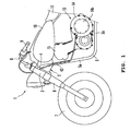
- the motorcycle 1 shown in FIG.1 includes a frame 2.
- the frame 2 has a steering head pipe 3, a mainframe member 4, and a down tube 5.
- the steering head pipe 3 supports a front fork 6.
- a steering handle 8 that steers a front wheel 7 is fixed on the upper end of the front fork 6.
- the clutch lever 9 as an example of an operation element is attached to the left end part of the steering handle 8.
- the main frame member 4 extends backwards from the steering head pipe 3, and supports a fuel tank 10 and a seat 11.
- the down tube 5 has: a first portion 5a that extends downwards from the front end of the main frame member 4; and a second portion 5b that extends backwards from the lower end of the first portion 5a.
- a power unit 13 is supported by the frame 2.
- the power unit 13 has a crankcase 14 and a cylinder 15.
- the friction clutch 30 (refer to FIG. 2 ) is housed in the crankcase 14.
- the clutch lever 9 and the friction clutch 30 are connected through the clutch wire 43.
- the clutch lever 9, the clutch wire 43, and the friction clutch 30 constitute a clutch operation device that manually engages or disengages the transmission of torque in the power unit 13.
- the engine 20 is disposed in the power unit 13.
- the engine 20 includes a piston 16, a crankshaft 18, and a connecting rod 17 that connects the piston 16 and the crankshaft 18.
- a main shaft 21 and a drive shaft 22 are arranged in parallel with the crankshaft 18 in the crankcase 14.
- a plurality of gears 23 are disposed around the main shaft 21 and the drive shaft 22.
- the transmission 25 is formed by the main shaft 21, the drive shaft 22, and the gear 23.
- the friction clutch 30 is disposed at the left end of the main shaft 21.
- a portion of the main shaft 21 where the friction clutch 30 is disposed is referred to as "clutch shaft 31."
- the clutch shaft 31 is part of the main shaft 21.
- the clutch shaft 31 and the main shaft 21 are formed integrally.
- the friction clutch 30 in this embodiment is the friction clutch of a wet multi plate type.
- the friction clutch according to the present invention is not limited to the friction clutch of a wet multi plate type.
- the friction clutch 30 includes a clutch housing 32 and a clutch boss 34.
- the clutch housing 32 is rotatably supported by the clutch shaft 31.
- the clutch boss 34 is supported by the clutch shaft 31 so as to rotate together with the clutch shaft 31.
- a plurality of friction plates 33 are disposed in the clutch housing 32, and a plurality of clutch plates 35 are disposed at the clutch boss 34.
- the friction plates 33 and the clutch plates 35 are arranged alternately along the shaft direction (right and left direction) of the clutch shaft 31.
- a drive gear 19 is fixed to the left end of the crankshaft 18.
- a driven gear 36 is fixed to the clutch housing 32.
- the drive gear 19 and the driven gear 36 are engaged, and the driven gear 36 rotates in accordance with the drive gear 19. Therefore, the clutch housing 32 rotates in accordance with the crankshaft 18.
- the drive gear 19 and the driven gear 36 constitute a speed reduction mechanism.
- the pressure plate 37 is disposed at the left side of the clutch shaft 31.
- a clutch spring 38 made with a diaphragm spring is attached to the pressure plate 37.
- the clutch spring 38 is not limited to a specific kind.
- the pressure plate 37 is slidable in the shaft direction of the clutch shaft 31, and urged to the clutch boss 34 side (right side in FIG. 3 ) at all times by the clutch spring 38.
- the friction plate 33 and the clutch plate 35 are press-fit, and the friction clutch 30 is set in an engagement state (clutch-in state).
- the pressure plate 37 separates from the clutch boss 34, engagement between the friction plate 33 and the clutch plate 35 is released, and the friction clutch 30 is set in a disengagement state (clutch-out state).
- the crankcase 14 includes: a case body 14a that has the support plate 14c; and a clutch cover 14b.
- the support plate 14c is arranged at the outside (left side) of the pressure plate 37.
- the clutch cover 14b is arranged at the outside of the support plate 14c.
- the clutch cover 14b covers the support plate 14c and the friction clutch 30 from the outside.
- the clutch cover 14b also covers the clutch operation-assisting device 70 described later.
- a push shaft 39 is supported by the support plate 14c.
- the push shaft 39 is arranged on the same straight line as the clutch shaft 31, and arranged further outside (left side) of the clutch shaft 31.
- the pressure plate 37 is rotatably supported by the push shaft 39 through a bearing 40.
- the pressure plate 37 is unable to move in the shaft direction against the push shaft 39, but slides in the shaft direction in accordance with the push shaft 39.
- a phantom line 39a in FIG. 3 is a rotation center line of the push shaft 39.
- the phantom line 39a is also a rotation center line of the pressure plate 37.
- a cam plate 41 is attached to the left end of the push shaft 39.
- the push shaft 39 and the cam plate 41 are formed by different members.
- the push shaft 39 and the cam plate 41 may be formed integrally. That is, part of the push shaft 39 may form the cam plate 41.
- the cam plate 41 has a boss part 41a, and the push shaft 39 is fit to the boss part 41a.
- a compression coil spring 42 is arranged between the left side of the cam plate 41 and the clutch cover 14b.
- the cam plate 41 is constantly urged in the right direction by the compression coil spring 42.
- the compression coil spring 42 is not necessarily required.
- the cam plate 41, the ball 60, and the first rotation plate 51 constitute a so-called cam mechanism of ball cam type.
- the compression coil spring 42 which urges the cam plate 41 in the right direction, is not necessary as long as it functions as a cam mechanism.
- the boss part 41a of the cam plate 41 passes through a center hole of a first rotation plate 51.
- the boss part 41a of the cam plate 41 can move in the shaft direction in relation to the first rotation plate 51.
- the first rotation plate 51 is rotatably supported by the support plate 14c through a bearing 53.
- cam grooves 61 are arranged on the periphery of the surface (left side surface in FIG. 3 ) 51a of the first rotation plate 51.
- similar cam grooves 62 are formed in the back surface (right side surface in FIG. 3 ) 41b of the cam plate 41.
- These cam grooves 61, 62 are generally in the V shape in cross section.
- a ball 60 is arranged between the cam groove 61 of the first rotation plate 51 and the cam groove 62 of the cam plate 41.
- Numeral 60a is a plate that prevents the ball 60 from dropping out.
- a so-called ball cam type of cam mechanism is formed by the cam grooves 61, 62, and the ball 60. That is, when the first rotation plate 51 rotates, the ball 60 moves in the cam grooves 61, 62, and then the cam plate 41 is pushed out to the left side by the ball 60. As a result, the pressure plate 37 slides to the left side together with the push shaft 39, and the friction clutch 30 is set in a disengagement state.
- the clutch wire 43 includes an inner wire 43a made of metal, and an outer tube 43b made of synthetic resin that covers the inner wire 43a.
- the inner wire 43a is slidably inserted in the outer tube 43b, and being pulled out from the edge part of the outer tube 43b.
- the clutch operation-assisting device 70 includes a second rotation plate 52 and a spring unit 54, besides the first rotation plate 51, which is described above.
- the first rotation plate 51 is constituted by a sheet metal press process part, for example.
- the first rotation plate 51 includes a center part 55 of the generally circle shape, a wire connection part 56, and a gear part 57.
- the wire connection part 56 and the gear part 57 are located on opposite sides while having the center part 55 in between.
- the first rotation plate 51 is bent toward the inside in the clutch shaft direction (right side in FIG. 3 ) at a place 51b between the center part 44 and the gear part 57.
- the cam groove 61 is arranged on the periphery of the hole 58 of the center part 55.
- An engagement groove 59 and an engagement hole 63 are formed at the wire connection part 56.
- the engagement groove 59 is a portion around which the inner wire 43a of the clutch wire 43 is wound.
- the engagement groove 59 curves like a circle whose center is the center 58c of the hole 58.
- the engagement groove 59 is formed generally in the U shape in cross section, which opens upwards.
- an engagement element 64 in the shape of a column which is fixed at the tip of the inner wire 43a, is hooked into the engagement hole 63. According to this constitution, when the inner wire 43a is pulled, the first rotation plate 51 rotates counterclockwise around the push shaft 39 as the center.
- a bearing member 90 is fixed to the support plate 14c.
- a fixing method for the bearing member 90 is not limited specifically.
- the bearing member 90 is fixed to the support plate 14c by bolts 91a, 91b.
- fasters such as screws may be used, for example.
- the bearing member 90 may be fixed to the support plate 14c by jointing.
- the bearing member 90 may be formed integrally on the support plate 14c. That is, the bearing member 90 may be a separate unit from the support plate 14c, or may be formed with the support plate 14c as a single unit.
- the bearing member 90 supports the second rotation plate 52.
- the second rotation plate 52 is constituted so as to rotate about a pivot shaft 65 that is a rotation center of the bearing member 90.
- teeth 52a are formed on the second rotation plate 52.
- the teeth 52a of the second rotation plate 52 are engaged with teeth 57a of the gear part 57 of the first rotation plate 51.
- the first rotation plate 51 and the second rotation plate 52 are connected so as to transmit the torque from one to another by the teeth 52a, 57a. Therefore, the second rotation plate 52 rotates in accordance with the first rotation plate 51 (refer to FIG. 5(a) ).
- the bearing member 90 includes a bearing 90a made with a ball bearing.
- the bearing 90a of the bearing member 90 does not have to be a ball bearing, but may be any type of roller bearing.
- the shape and structure are not limited to a roller bearing, as long as the mechanism allows the rotation of the second rotation plate 52 that has the pivot shaft 65 as a rotation center.
- the distance between the rotation center (shaft center 39a of the push shaft 39) of the first rotation plate 51 and the teeth 57a is longer than the distance between the rotation center (shaft center of the pivot shaft 65) of the second rotation plate 52 and the teeth 52a. Therefore, the first rotation plate 51 and the second rotation plate 52 are connected in a way that a turning angle of the second rotation plate 52 is larger than a turning angle of the first rotation plate 51.
- the spring unit 54 includes a spring holder 66 and an auxiliary spring 67.
- the spring holder 66 is constituted by an inner tube 66a and an outer tube 66b.
- the inner tube 66a and the outer tube 66b are slidably fit in the shaft direction.
- the outer tube 66b slides in relation to the inner tube 66a so that the spring holder 66 can be stretched compressed or contract.
- the inner tube 66a has a spring retainer 68 and a support end 69.
- the spring retainer 68 juts out in the shape of a flange from an outer peripheral surface of one end of the inner tube 66a.
- the support end 69 is formed at one end of the inner tube 66a, and rotatably supported by a mounting seat 14d of the support plate 14c.
- the outer tube 66b has the spring retainer 71 and a connection end 72.
- the spring retainer 71 juts out in the shape of a flange from an outer peripheral surface of one end of the outer tube 66b.
- the connection end 72 is formed at one end of the outer tube 66b, and rotatably connected to one end of the second rotation plate 52 through a pin 73.
- the auxiliary spring 67 is a compression coil spring.
- the auxiliary spring 67 is set between the spring retainer 68 of the inner tube 66a and the spring retainer 71 of the outer tube 66b, in a compressed state. Therefore, the spring holder 66 is urged in the extending direction at all times.
- the auxiliary spring 67 changes the extension direction S2 with the support end 69 as a pivot while shifting from a returning position (refer to FIG. 5(a) ) through a disengagement starting position (refer to FIG. 6(a) ) to a disengagement position (refer to FIG. 7(a) ), which are described later.
- the extension direction S2 of the auxiliary spring 67 and the shaft center 39a of the push shaft 39 do not cross at any place, as seen from the shaft direction of the push shaft 39.
- a wire introduction port 74 is formed at the case body 14a of the crankcase 14.
- the clutch wire 43 is inserted in the wire introduction port 74.
- the inner wire 43a of the clutch wire 43 is introduced in the crankcase 14 through the wire introduction port 74, and connected to the wire connection part 56 of the first rotation plate 51.
- the support plate 14c is provided with a first hole 47 and a second hole 48 in addition to a hole, to which the push shaft 39 is inserted.
- the first hole 47 and the second hole 48 are located opposite from each other with the shaft center 39a of the push shaft 39 in between.
- Part of the wire connection part 56 of the first rotation plate 51 is located in the first hole 47 (refer to FIG. 3 ).
- Part of the second rotation plate 52 and the spring unit 54 are located in the second hole 48 (refer to FIG. 3 ).
- the clutch lever 9 can rotate between the returning position where the friction clutch 30 maintains a clutch-in state and the disengagement position where the friction clutch 30 is set clutch-off.
- a predetermined rotation range from the returning position (for example, a rotation range where the moving distance of the tip of the clutch lever 9 is between 10 and 15 mm) is a so-called play region, in which a clutch-off state is maintained while the clutch lever 9 is grasped.
- operation of the clutch lever 9 pulls the clutch wire 43 only slightly so that urging force of the clutch spring 38 is not transmitted to the clutch lever 9.
- the very end of play of the clutch lever 9 is the disengagement starting position. In the disengagement starting position, urging force of the clutch spring 38 works on the clutch lever 9 through the clutch wire 43.
- FIG. 5 (a) and (b) indicate a state of the clutch operation-assisting device 70 where the clutch lever 9 is in the returning position.
- the pin 73 that connects the second rotation plate 52 and the spring unit 54 is positioned upwards, above a straight line S1 that connects the support end 69 of the spring holder 66 and the pivot shaft 65 of the second rotation plate 52.
- the first rotation plate 51 When the clutch lever 9 is operated from the disengagement starting position to the disengagement position, the first rotation plate 51 further rotates counterclockwise. Then, as shown in FIG. 7 (b) , the position between the cam groove 61 of the first rotation plate 51 and the cam groove 62 of the cam plate 41 is deviated. Accordingly, the ball 60 moves in both cam grooves 61, 62, and the cam plate 41 is pushed outside. As shown in FIG. 7 (a) , the second rotation plate 52 further rotates clockwise in accordance with the rotation of the first rotation plate 51, then a position of the pin 73 is deviates downwards than the straight line S1.
- the spring holder 66 extends by receiving the urging force of the auxiliary spring 67, and the urging force of the auxiliary spring 67 functions as force to rotate the second rotation plate in a clockwise direction.
- the urging force of the auxiliary spring 67 functions as assisting force to rotate the first rotation plate 51 in counterclockwise direction.
- a countervailing spring unit 80 that countervails the inverse assisting force is disposed in the clutch operation-assisting device 70 in the present embodiment.
- a housing part 81 that houses the countervailing spring unit 80 is formed in the support plate 14c.
- the countervailing spring unit 80 has a pressing pin 82 and a countervailing spring 83.
- a flange-shape stopper 84 is formed at the bottom end of the pressing pin 82.
- the pressing pin 82 is inserted in the housing part 81 from below.
- a spring retainer 85 that supports the bottom end of the countervailing spring 83 is disposed in the support plate 14c.
- the countervailing spring 83 is a compression coil spring, and is disposed between the upper-end-inner-surface of the pressing pin 82 and the spring retainer 85 in a compression state.
- the countervailing spring 83 continually biases or urges the pressing pin 82 obliquely upwards along the longitudinal direction of the housing part 81. Urging force of the countervailing spring 83 is set slightly weaker than the inverse assisting force of the auxiliary spring 67.
- the pressing pin 82 can move between the first position (refer to FIG. 6(a) and FIG. 7(a) ) where the upper end protrudes largely from the housing part 81 and the second position (refer to FIG. 5(a) ) where the upper end of the pressing pin 82 protrudes slightly from the housing part 81.
- a stopper 84 of the pressing pin 82 collides or engages with the lower end of the housing part 81 to restrict a position of the pressing pin 82.
- the stopper 84 of the pressing pin 82 collides or engages with the spring retainer 85 to restrict a position of the pressing pin 82.
- the clutch operation-assisting device 70 includes the push shaft 39, the first rotation plate 51, and the auxiliary spring 67.
- the push shaft 39 rotatably supports the pressure plate 37, and slides in the shaft direction together with the pressure plate 37.
- the first rotation plate 51 is connected to the clutch wire 43.
- the first rotation plate 51 slides the push shaft 39 by means of rotation in accordance with the clutch wire 43.
- the auxiliary spring 67 changes the extension direction S2 and provides the urging force that rotates the first rotation plate 51 in the direction that disengages the friction clutch 30, when the clutch lever 9 is operated in the direction that disengages the friction clutch 30, while the clutch lever 9 shifts from the disengagement starting position where the clutch lever 9 receives counter force of the clutch spring 38 to the disengagement position where disengagement of the friction clutch 30 is completed.
- the clutch operation-assisting device 70 in the present embodiment it is not necessary to set the auxiliary spring 67 from the shaft center 39a of the push shaft 39 along the radius direction, so that the auxiliary spring 67 can be set relatively freely without being restricted by the push shaft 39. Therefore, a setting space for the auxiliary spring 67 can be maintained largely without enlarging the crankcase 14 of the power unit 13. As a result, the power unit 13 can be downsized.
- an extension space for the auxiliary spring 67 can be maintained large, an extension length for the auxiliary spring 67 can be set long. Therefore, without using a particularly expensive spring, sufficient urging force can be attained by keeping an extension length long. Therefore, the clutch operation-assisting device 70 can be reduced in cost.
- the clutch operation-assisting device 70 rotates around the pivot shaft 65 as a center, and includes the second rotation plate 52 that transmits the urging force of the auxiliary spring 67 to the first rotation plate 51. As seen from the shaft direction of the push shaft 39, the position of the pivot shaft 65 and the position of the push shaft 39 are deviated.
- the second rotation plate 52 which provides urging force of the auxiliary spring 67 to the first rotation plate 51, is set between the spring unit 54 and the first rotation plate 51. Therefore, restriction for the setting position of the auxiliary spring 67 is further reduced, and downsizing of the power unit 13 can be promoted.
- the bearing member 90 that rotatably supports the second rotation plate 52 is disposed, and the bearing member 90 is fixed to the support plate 14c. Therefore, the second rotation plate 52 can stably be supported. Also, the second rotation plate 52 can be positioned precisely when the clutch operation-assisting device 70 is set. Thus, transmission of the assisting force from the spring unit 54 through the second rotation plate 52 to the first rotation plate 51 is smoothed. As a result, transmission of subtle friction force and the like to the rider's hand that grips on the clutch lever 9 is restrained, so that operation of the clutch lever 9 by the rider is smoothed.
- the second rotation plate 52 is not supported by the clutch cover 14b.
- the second rotation plate 52 can rotatably be supported even in a state where the clutch cover 14b is removed. Therefore, it is possible to adjust the clutch operation-assisting device 70 (for example, adjustment of the disengagement starting position) in a state where the clutch cover 14b is removed. Therefore, according to the clutch operation-assisting device 70, maintainability can be improved.
- the bearing member 90 supports the second rotation plate 52 from the outside in the clutch shaft direction (left side in FIG. 3 ).
- the first rotation plate 51 bends to the inside in the clutch shaft direction (right side in FIG. 3 ) at the place 51b between the center part 55 and the teeth 57a of the gear part 57. Therefore, the second rotation plate 52 can be arranged more inside.
- the bearing member 90 is arranged between the second rotation plate 52 and the clutch cover 14b, the second rotation plate 52 can be arranged more inside, so the clutch cover 14b can be restrained from protruding outside. In other words, interference between the clutch cover 14b and the bearing member 90 can be avoided without arranging the clutch cover 14b further outside.
- a bearing 90a of a bearing member 90 is a ball bearing. Therefore, the second rotation plate 52 can be supported more smoothly, and operation of the clutch lever 9 by the rider can be smoother.
- the first rotation plate 51 and the second rotation plate 52 are connected in a way that a turning angle of the second rotation plate 52 is larger than a turning angle of the first rotation plate 51.
- auxiliary spring 67 can be downsized or reduced in cost.
- the first rotation plate 51 includes: a wire connection part 56 connected to the clutch wire 43; and the gear part 57 connected to the second rotation plate 52.
- the wire connection part 56 and the gear part 57 are located opposite from each other while having the push shaft 39 in between, as seen from the shaft direction of the clutch shaft 31.
- the wire connection part 56 and the gear part 57 can be compactly arranged, so that downsizing of the power unit 13 can be promoted.
- one end of the auxiliary spring 67 (specifically, the support end 69 of the spring holder 66) is swingably supported by the support plate 14c.
- the support plate 14c may directly support the auxiliary spring 67, or may indirectly support the auxiliary spring 67 through other members.
- the clutch operation-assisting device 70 includes a support plate 14c located between the friction clutch 30 and the first rotation plate 51.
- the holes 47, 48 are formed in the support plate 14c.
- the first rotation plate 51 can firmly be supported by the support plate 14c, and sufficient strength can be maintained.
- lubricating oil can be supplied from the friction clutch 30 side to the first rotation plate 51 side. Therefore, friction of the swing part of the clutch operation-assisting device 70 can be restrained.
- part of the first rotation plate 51 (specifically, part of the wire connection part 56) is inserted in the hole 47 of the support plate 14c. Furthermore, the auxiliary spring 67 is inserted in the hole 48 of the support plate 14c. Also, part of the second rotation plate 52 is inserted in the hole 48.
- the power unit 13 can be downsized in the width direction (shaft direction of the push shaft 39, right and left direction in this embodiment). Also, by the amount of overlap between the auxiliary spring 67 and the support plate 14c, the power unit 13 can be downsized. Furthermore, by the amount of overlap between the second rotation plate 52 and the support plate 14c, the power unit 13 can be downsized. In the present embodiment, the power unit 13 is "transversely mounted" as we call it, and the width direction of the power unit 13 corresponds with the vehicle width direction. Therefore, downsizing of the motorcycle 1 can be promoted.
- the first hole 47 and the second hole of the support plate 14c are located opposite from each other while having the push shaft 39 in between.
- the clutch operation-assisting device 70 in the present embodiment includes the cam mechanism of ball cam type that slides the push shaft 39 in accordance with the rotation of the first rotation plate 51.
- the clutch operation-assisting device 70 includes the cam plate 41 that slides in the shaft direction together with the push shaft 39.
- the cam plate 41 is provided with a cam surface 41b, which extends in the orthogonal direction to the push shaft 39 and has a cam groove 62.
- the cam groove 61 is formed, and also a cam surface 51a, which faces against the cam surface 41b of the cam plate 41, is formed.
- the clutch operation-assisting device 70 is arranged between the cam groove 62 of the cam plate 41 and the cam groove 61 of the first rotation plate 51, and includes the ball 60 that slides the cam plate 41 in the shaft direction of the push shaft 39 in accordance with the rotation of the first rotation plate 51.
- the first rotation plate 51 itself which is connected to the clutch wire 43, functions as a cam plate.
- a pair of cam plates which constitutes the cam mechanism of ball cam type, is not necessarily disposed separately. Therefore, also in this point, downsizing of the power unit 13 in the width direction can be achieved. Also, downsizing of the vehicle can be promoted.
- the cam plate 41 is disposed at the outside end of the push shaft 39, and the first rotation plate 51 is arranged more inside than the cam plate 41.
- the first rotation plate 51 is arranged more inside than the ball 60. Therefore, the first rotation plate 51 can be arranged more inside, and downsizing of the power unit 13 can be promoted. Also, by arranging the first rotation plate 51 more inside, the second rotation plate 52 can be arranged more inside.
- the first gear teeth 57a are formed in the first rotation plate 51.
- the second gear teeth 52a which engages with the first gear teeth 57a within the surface orthogonal to the push shaft 39, is formed in the second rotation plate 52. That is, the first rotation plate 51 and the second rotation plate 52 are connected by gear.
- the first rotation plate 51 and the second rotation plate 52 rotate within the same surface. Therefore, the entire length in the shaft direction of the first rotation plate 51 and the second rotation plate 52 is shortened. Therefore, downsizing of the power unit 13 in the width direction can be promoted.
- the first rotation plate 51 and the second rotation plate 52 may be connected by a cam mechanism or the like, of course. Connection embodiment between the first rotation plate 51 and the second rotation plate 52 is not limited to an example of the present embodiment.
- Downsizing of the bearing member 90 which is used to support the second rotation plate 52 in the present embodiment, is intended to be achieved by being supported by the bolts 91a, 91b in relation to the support plate 14c, and by forming a bearing mechanism.
- the rotational direction of the second rotation plate is maintained in a surface that is orthogonal to the shaft direction (pivot shaft 65) of the bearing member 90.
- torque from the first rotation plate is transmitted accurately.
- the clutch operation-assisting device 70 includes a countervailing spring 83 that provides the urging force to countervail the urging force of the auxiliary spring 67 added to the first rotation plate 51 when the clutch lever 9 is in the returning position.
- the clutch operation-assisting device according to the present invention is applied to a motorcycle.
- the clutch operation-assisting device according to the present invention can be applied to straddle type vehicles other than motorcycles.
- one part 51b of the first rotation plate 51 is bent so that the teeth 57a of the gear part 57 is located more inside than the center part 55.
- the first rotation plate 51 is acceptable as long as the teeth 57a of the gear part 57 are located more inside than the center part 55. This may be achieved by curving the rotation plate 51, without the use of a defined bend.
- the pressure plate means the member that press-fits the friction plate of the friction clutch and the clutch plate.
- the pressure plate is not limited to the plate shape.
- the clutch spring is not limited to a diaphragm spring, but can be other kinds of spring such as a coil spring.
- the push shaft 39 corresponds to the "sliding member" of the present invention.
- the sliding member is not limited to the push shaft 39. Any member is acceptable as long as it rotatably supports the pressure plate 37 and slides in the predetermined direction together with the pressure plate 37.
- the sliding member may be a single member or a combination of two or more members.
- the rotation center of the first rotation member (first rotation plate 51) and the rotation center of the pressure plate 37 are the same. However, these may be deviated. In that case, for example, a seesaw-like member may be disposed between the cam plate 41 and the push shaft 39. Accordingly, a sliding member can be slid by rotating the first rotation member along with the transmission member. For a mechanism to slide the sliding member, any type is acceptable as long as it includes the first rotation member.
- Transmission member in the present invention is not limited to the wire shape, but may be the rod shape.
- “Auxiliary elastic member” in the present invention is not limited to the coil spring, but may be other elastic member such as a gas spring.
- first rotation plate 51 and the second rotation plate 52 are connected by gear.
- first rotation plate 51 and the second rotation plate 52 may be connected by other engagement embodiment such as link connection.
- the present invention is useful for the clutch operation-assisting device that reduces the operation force of the friction clutch, and useful for the power unit and the straddle type vehicle including the same.
Landscapes
- Engineering & Computer Science (AREA)
- General Engineering & Computer Science (AREA)
- Mechanical Engineering (AREA)
- Mechanical Operated Clutches (AREA)
- Arrangement And Mounting Of Devices That Control Transmission Of Motive Force (AREA)
Abstract
Description
- The present invention relates to a clutch operation-assisting device for reducing the operation force of a friction clutch when torque transmission is disengaged by the friction clutch, and relates to a power unit and a straddle type vehicle including the same.
- Power units for motorcycles, for example, include a friction clutch for engaging and disengaging torque from an engine to a transmission. The friction clutch has a clutch shaft, and a friction plate and a clutch plate that contact each other in the shaft direction of the clutch shaft (hereinafter, referred to as clutch shaft direction). Also, the friction clutch includes a pressure plate that engages the friction plate and the clutch plate, and a clutch spring that urges the pressure plate. Under normal conditions, the friction clutch is maintained in a clutch-in state that allows torque transmission by the clutch spring.
- The friction clutch has a clutch release mechanism. The clutch release mechanism is provided for releasing pressure on the pressure plate caused by the clutch spring. The clutch release mechanism is connected to a clutch lever through a clutch wire. Therefore, when a rider grasps the clutch lever, the pressure plate slides against the urging force of the clutch spring, and torque transmission from the friction plate to the clutch plate is disengaged.
- In a high-powered and high-speed type engine, it is desirable that an attachment load of the clutch spring be set high in order to increase a torque capacity. However, it is typically intended for clutch lever operation to be performed by a human hand, and as such if an attachment load of the clutch spring is set high, the burden of operating the clutch lever is increased.
- As a means to solve this, clutch operation-assisting devices that have an assist mechanism for reducing operation force of the clutch lever in a clutch release mechanism to which the clutch wire is connected are known. Such operation assist devices are known from, for example,
JP-A-Hei 7-132872 JP-A-Sho 55-94028 - The clutch operation-assisting device disclosed in
JP-A-Hei 7-132872 JP-A-Sho 55-94028 - As shown in
FIG. 9 , the clutch operation-assisting device disclosed inJP-A-Sho 55-94028 rotatable push lever 525 connected to aclutch wire 528, and an assistingspring 529 that reduces the operation force of the clutch lever. Oneend 529a of the assistingspring 529 is connected to thepush lever 525, and the other end of the assistingspring 529 is connected to acommunication member 531 formed in the arc shape. Thepush lever 525 is fixed to apush screw 517 located on the same straight line (on the straight line extending in the direction from the face to the reverse side of paper of theFIG. 9 ) as the clutch shaft. Thepush lever 525 rotates together with thepush screw 517. On the other hand, thecommunication member 531 is rotatably supported to apin 530, and rotates about thepin 530. - When the clutch lever is in a so-called play state (in other words, in a state where no load is applied when the clutch lever is pulled), the assisting
spring 529 locates on a straight line M1 that connects a rotation center CO of thepush lever 525 and thepin 530, as shown inFIG. 9 . In other words, the extension direction passes through the rotation center CO of thepush lever 525. Therefore, urging force of the assistingspring 529 does not function as a force to rotate thepush lever 525. - On the other hand, as indicated by a chain double-dashed line in
FIG. 9 , when the clutch lever is pulled, thepush lever 525 is dragged and rotates counterclockwise. As a result, the position of the assistingspring 529 changes, and the extension direction M2 of the assistingspring 529 deviates from the rotation center CO of thepush lever 525. Accordingly, part of urging force of the assistingspring 529 functions as a force to rotate thepush lever 525 counterclockwise. Therefore, urging force of the assistingspring 529 functions as an assisting force in pulling the clutch lever, and operation force of the clutch lever is reduced. - In this way, in the clutch operation-assisting device described above, the assisting
spring 529 changes the position as it transitions from the initial position where the clutch lever is in a play state to the disengagement position where the friction clutch is disengaged. In the initial location, the extension direction M1 of the assistingspring 529 passes through a shaft center (=rotation center CO) of thepush screw 517. Therefore, in the clutch operation-assisting device described above, the assistingspring 529 must be disposed along the radial direction from the shaft center of thepush screw 517, and it is difficult to sufficiently maintain an installation space for the assistingspring 529. Also, it is difficult to sufficiently maintain the extension length of the assistingspring 529. Therefore, in the clutch operation-assisting device described above, the power unit must be upsized in order to sufficiently maintain the installation space for the assistingspring 529. - This invention is made in view of the above points, and an object of the invention is to downsize the power unit that has the built-in clutch operation-assisting device.
- According to a first aspect of the present invention there is provided a clutch operation-assisting device adapted to be positioned between a clutch operating element and a friction clutch having a pressure plate and a clutch spring for urging the pressure plate towards an engaged configuration, the clutch operation-assisting device comprising:
- a sliding member adapted to rotatably support the pressure plate and slide in a predetermined direction together with the pressure plate;
- a first rotation member adapted to be coupled to the clutch operating element via a transmission member, wherein the first rotation member rotates in accordance with the transmission member to cause the sliding member to slide;
- a support plate that rotatably supports the first rotation member;
- an elastic member adapted to apply an urging force along a line of expansion/contraction on the first rotation member,
wherein the expansion/contraction direction of the elastic member does not pass through a rotation center of the pressure plate; - a second rotation member arranged to transmit the urging force of the elastic member to the first rotation member; and
- a bearing member supported by the support plate, and arranged to rotatably support the second rotation member.
- The bearing member and support plate may be integrally formed. The bearing member and support plate may be separately formed.
- Said device may be adapted to be housed in a casing of a power unit. The casing may have a cover that covers the first rotation member, the support plate, the elastic member, and the bearing member from the outside.
- The first rotation member may have a rotation center part supported by the support plate, and a connection part connected to the second rotation member. Part of the first rotation member may be bent so that the connection part is located more inside than the rotation center part.
- The bearing member may support the second rotation member from the outside.
- The bearing member may comprise a ball bearing.
- According to a second aspect of the present invention there is provided a power unit for a vehicle comprising:
- a friction clutch having a pressure plate and a clutch spring for urging the pressure plate, wherein the friction clutch is connected via a transmission member to an operation element;
- a sliding member arranged to rotatably support the pressure plate and slide in a predetermined direction together with the pressure plate;
- a first rotation member adapted to be coupled to the clutch operating element via a transmission member, wherein the first rotation member rotates in accordance with the transmission member to cause the sliding member to slide;
- a support plate that rotatably supports the first rotation member;
- an elastic member adapted to apply an urging force along a line of expansion/contraction on the first rotation member,
wherein the expansion/contraction direction of the elastic member does not pass through a rotation center of the pressure plate; - a second rotation member arranged to transmit the urging force of the auxiliary elastic member to the first rotation member;
- a bearing member supported by the support plate and arranged to rotatably support the second rotation member; and
- a casing that houses the friction clutch, the sliding member, the first rotation member, the support plate, the elastic member, the second rotation member, and the bearing member.
- According to a third aspect of the present invention there is provided a straddle-type vehicle comprising a power unit according to the second aspect.
- A clutch operation-assisting device may be disposed in a clutch operation device, and housed in a casing of a power unit, the clutch operation device may include: a friction clutch having a pressure plate and a clutch spring that urges the pressure plate, and arranged in the casing of the power unit; and an operation element that is connected to the friction clutch through a transmission member, and manually operated against urging force of the clutch spring when torque transmission by the friction clutch is disengaged, the clutch operation-assisting device including: a sliding member that rotatably supports the pressure plate and slides in a predetermined direction together with the pressure plate; a first rotation member that is connected to the transmission member and slides the sliding member by rotating along with the transmission member; a support plate that rotatably supports the first rotation member; an auxiliary elastic member that changes an expansion direction and provides urging force to rotate the first rotation member in a direction that disengages the friction clutch, when the operation element is operated in a direction that disengages the friction clutch, while the operation element shifts from a disengagement starting position where the operation element receives counter force of the clutch spring to a disengagement position where disengagement of the friction clutch is completed; the second rotation member that is connected to the auxiliary elastic member and connected to the first rotation member, and transmits urging force of the auxiliary elastic member to the first rotation member by rotation; and a bearing member that is fixed to the support plate or integrally formed in the support plate, and rotatably supports the second rotation member; in which an expansion direction of the auxiliary elastic member does not pass through a rotation center of the pressure plate, as seen from a sliding direction of the sliding member.
- According to the clutch operation-assisting device described above, the expansion direction of the auxiliary elastic member does not pass through the rotation center of the pressure plate as seen from the sliding direction of the sliding member. Therefore, the auxiliary elastic member need not be disposed along the radial direction from the rotation center of the pressure plate, as seen from the sliding direction. Therefore, the auxiliary elastic member can be disposed without restriction of the sliding member. Thus, an installation space for the auxiliary elastic member can be largely maintained without upsizing the power unit itself. Also, a space for the auxiliary elastic member to expand or contract can be largely maintained. As a result, the power unit can be downsized.
- According to the clutch operation-assisting device described above, the second rotation member is fixed to the support plate or supported by the integrated bearing member. Therefore, the second rotation member is stably supported. Also, positioning accuracy for installing the second rotation member is improved. Therefore, transmission of force from the auxiliary elastic member through the second rotation member to the first rotation member goes smoothly, and also operation of the operation element by an operator goes smoothly.
- As described above, according to the present invention, the power unit that has the built-in clutch operation-assisting device can be downsized.
- These and other aspects of the present invention will now be described, by way of example only, with reference to the accompanying drawings, in which:
-
FIG. 1 is a left side view representing a portion of a motorcycle; -
FIG. 2 is a sectional view illustrating a portion of a power unit in a cut-across way; -
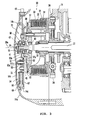
FIG. 3 is a sectional view of a clutch operation-assisting device; -
FIG. 4(a) is a front view of a first rotation plate; -
FIG. 4(b) is a front view of a cam plate; -
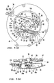
FIG. 5 is a drawing that represents a clutch operation-assisting device while a clutch lever is in a returning position, whereinFIG. 5 (a) is a side view andFIG. 5(b) is a sectional view; -
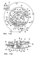
FIG. 6 is a drawing that represents a clutch operation-assisting device while a clutch lever is in a disengagement starting position, whereinFIG. 6 (a) is a side view andFIG. 6(b) is a sectional view; -
FIG. 7 is a drawing that represents a clutch operation-assisting device while a clutch lever is in a disengagement position, whereinFIG. 7 (a) is a side view andFIG. 7(b) is a sectional view; -
FIG. 8 is a side view of a countervailing spring unit in a clutch operation-assisting device while a clutch lever is in a returning position; and -
FIG. 9 is a side view of a conventional clutch operation-assisting device. - The
motorcycle 1 shown inFIG.1 includes aframe 2. Theframe 2 has a steering head pipe 3, a mainframe member 4, and adown tube 5. The steering head pipe 3 supports a front fork 6. A steering handle 8 that steers a front wheel 7 is fixed on the upper end of the front fork 6. The clutch lever 9 as an example of an operation element is attached to the left end part of the steering handle 8. - The main frame member 4 extends backwards from the steering head pipe 3, and supports a
fuel tank 10 and a seat 11. The downtube 5 has: a first portion 5a that extends downwards from the front end of the main frame member 4; and asecond portion 5b that extends backwards from the lower end of the first portion 5a. - A
power unit 13 is supported by theframe 2. Thepower unit 13 has acrankcase 14 and acylinder 15. As described later, the friction clutch 30 (refer toFIG. 2 ) is housed in thecrankcase 14. The clutch lever 9 and the friction clutch 30 are connected through theclutch wire 43. In the example embodiment shown, the clutch lever 9, theclutch wire 43, and the friction clutch 30 constitute a clutch operation device that manually engages or disengages the transmission of torque in thepower unit 13. - As shown in
FIG. 2 , theengine 20 is disposed in thepower unit 13. Theengine 20 includes apiston 16, acrankshaft 18, and a connectingrod 17 that connects thepiston 16 and thecrankshaft 18. Amain shaft 21 and adrive shaft 22 are arranged in parallel with thecrankshaft 18 in thecrankcase 14. A plurality ofgears 23 are disposed around themain shaft 21 and thedrive shaft 22. Thetransmission 25 is formed by themain shaft 21, thedrive shaft 22, and thegear 23. - The
friction clutch 30 is disposed at the left end of themain shaft 21. Hereinafter, for convenience, a portion of themain shaft 21 where thefriction clutch 30 is disposed is referred to as "clutch shaft 31." In this embodiment, theclutch shaft 31 is part of themain shaft 21. Theclutch shaft 31 and themain shaft 21 are formed integrally. - As shown in
FIG. 3 , the friction clutch 30 in this embodiment is the friction clutch of a wet multi plate type. However, the friction clutch according to the present invention is not limited to the friction clutch of a wet multi plate type. Thefriction clutch 30 includes aclutch housing 32 and a clutch boss 34. Theclutch housing 32 is rotatably supported by theclutch shaft 31. The clutch boss 34 is supported by theclutch shaft 31 so as to rotate together with theclutch shaft 31. - A plurality of
friction plates 33 are disposed in theclutch housing 32, and a plurality ofclutch plates 35 are disposed at the clutch boss 34. Thefriction plates 33 and theclutch plates 35 are arranged alternately along the shaft direction (right and left direction) of theclutch shaft 31. - As shown in
FIG. 2 , adrive gear 19 is fixed to the left end of thecrankshaft 18. A drivengear 36 is fixed to theclutch housing 32. Thedrive gear 19 and the drivengear 36 are engaged, and the drivengear 36 rotates in accordance with thedrive gear 19. Therefore, theclutch housing 32 rotates in accordance with thecrankshaft 18. Thedrive gear 19 and the drivengear 36 constitute a speed reduction mechanism. - As shown in
FIG. 3 , thepressure plate 37 is disposed at the left side of theclutch shaft 31. Aclutch spring 38 made with a diaphragm spring is attached to thepressure plate 37. Here, theclutch spring 38 is not limited to a specific kind. Thepressure plate 37 is slidable in the shaft direction of theclutch shaft 31, and urged to the clutch boss 34 side (right side inFIG. 3 ) at all times by theclutch spring 38. When thepressure plate 37 moves to the clutch boss 34 side and presses thefriction plate 33, thefriction plate 33 and theclutch plate 35 are press-fit, and thefriction clutch 30 is set in an engagement state (clutch-in state). On the other hand, when thepressure plate 37 separates from the clutch boss 34, engagement between thefriction plate 33 and theclutch plate 35 is released, and thefriction clutch 30 is set in a disengagement state (clutch-out state). - The
crankcase 14 includes: acase body 14a that has thesupport plate 14c; and aclutch cover 14b. Thesupport plate 14c is arranged at the outside (left side) of thepressure plate 37. Theclutch cover 14b is arranged at the outside of thesupport plate 14c. Theclutch cover 14b covers thesupport plate 14c and the friction clutch 30 from the outside. Theclutch cover 14b also covers the clutch operation-assistingdevice 70 described later. - A
push shaft 39 is supported by thesupport plate 14c. Thepush shaft 39 is arranged on the same straight line as theclutch shaft 31, and arranged further outside (left side) of theclutch shaft 31. Thepressure plate 37 is rotatably supported by thepush shaft 39 through abearing 40. Thepressure plate 37 is unable to move in the shaft direction against thepush shaft 39, but slides in the shaft direction in accordance with thepush shaft 39. Aphantom line 39a inFIG. 3 is a rotation center line of thepush shaft 39. Thephantom line 39a is also a rotation center line of thepressure plate 37. - A
cam plate 41 is attached to the left end of thepush shaft 39. In this embodiment, thepush shaft 39 and thecam plate 41 are formed by different members. However, thepush shaft 39 and thecam plate 41 may be formed integrally. That is, part of thepush shaft 39 may form thecam plate 41. In the present embodiment, thecam plate 41 has aboss part 41a, and thepush shaft 39 is fit to theboss part 41a. Acompression coil spring 42 is arranged between the left side of thecam plate 41 and theclutch cover 14b. Thecam plate 41 is constantly urged in the right direction by thecompression coil spring 42. Thecompression coil spring 42 is not necessarily required. As described later, thecam plate 41, theball 60, and thefirst rotation plate 51 constitute a so-called cam mechanism of ball cam type. - However, the
compression coil spring 42, which urges thecam plate 41 in the right direction, is not necessary as long as it functions as a cam mechanism. - The
boss part 41a of thecam plate 41 passes through a center hole of afirst rotation plate 51. Theboss part 41a of thecam plate 41 can move in the shaft direction in relation to thefirst rotation plate 51. Thefirst rotation plate 51 is rotatably supported by thesupport plate 14c through abearing 53. - As shown in
FIG. 4(a) , threecam grooves 61 are arranged on the periphery of the surface (left side surface inFIG. 3 ) 51a of thefirst rotation plate 51. On the other hand, as shown inFIG. 4 (b) ,similar cam grooves 62 are formed in the back surface (right side surface inFIG. 3 ) 41b of thecam plate 41. Thesecam grooves FIG. 3 , aball 60 is arranged between thecam groove 61 of thefirst rotation plate 51 and thecam groove 62 of thecam plate 41. Numeral 60a is a plate that prevents theball 60 from dropping out. A so-called ball cam type of cam mechanism is formed by thecam grooves ball 60. That is, when thefirst rotation plate 51 rotates, theball 60 moves in thecam grooves cam plate 41 is pushed out to the left side by theball 60. As a result, thepressure plate 37 slides to the left side together with thepush shaft 39, and thefriction clutch 30 is set in a disengagement state. - As shown in
FIG. 5(a) , theclutch wire 43 includes aninner wire 43a made of metal, and anouter tube 43b made of synthetic resin that covers theinner wire 43a. Theinner wire 43a is slidably inserted in theouter tube 43b, and being pulled out from the edge part of theouter tube 43b. - The clutch operation-assisting
device 70 includes asecond rotation plate 52 and aspring unit 54, besides thefirst rotation plate 51, which is described above. Thefirst rotation plate 51 is constituted by a sheet metal press process part, for example. As shown inFIG. 4 (a) , thefirst rotation plate 51 includes acenter part 55 of the generally circle shape, awire connection part 56, and agear part 57. Thewire connection part 56 and thegear part 57 are located on opposite sides while having thecenter part 55 in between. As shown inFIG. 3 andFIG. 4(a) , thefirst rotation plate 51 is bent toward the inside in the clutch shaft direction (right side inFIG. 3 ) at aplace 51b between the center part 44 and thegear part 57. - A
hole 58, through which thepush shaft 39 is inserted, is formed at thecenter part 55. Thecam groove 61 is arranged on the periphery of thehole 58 of thecenter part 55. Anengagement groove 59 and anengagement hole 63 are formed at thewire connection part 56. Theengagement groove 59 is a portion around which theinner wire 43a of theclutch wire 43 is wound. Theengagement groove 59 curves like a circle whose center is thecenter 58c of thehole 58. Theengagement groove 59 is formed generally in the U shape in cross section, which opens upwards. As shown inFIG. 5(a) , anengagement element 64 in the shape of a column, which is fixed at the tip of theinner wire 43a, is hooked into theengagement hole 63. According to this constitution, when theinner wire 43a is pulled, thefirst rotation plate 51 rotates counterclockwise around thepush shaft 39 as the center. - As shown in
FIG. 5(b) , a bearingmember 90 is fixed to thesupport plate 14c. A fixing method for the bearingmember 90 is not limited specifically. However, in the present embodiment, the bearingmember 90 is fixed to thesupport plate 14c bybolts bolts member 90 may be fixed to thesupport plate 14c by jointing. The bearingmember 90 may be formed integrally on thesupport plate 14c. That is, the bearingmember 90 may be a separate unit from thesupport plate 14c, or may be formed with thesupport plate 14c as a single unit. The bearingmember 90 supports thesecond rotation plate 52. Thesecond rotation plate 52 is constituted so as to rotate about apivot shaft 65 that is a rotation center of the bearingmember 90. - As shown in
FIG. 5(a) ,teeth 52a are formed on thesecond rotation plate 52. Theteeth 52a of thesecond rotation plate 52 are engaged withteeth 57a of thegear part 57 of thefirst rotation plate 51. Thefirst rotation plate 51 and thesecond rotation plate 52 are connected so as to transmit the torque from one to another by theteeth second rotation plate 52 rotates in accordance with the first rotation plate 51 (refer toFIG. 5(a) ). - The bearing
member 90 includes abearing 90a made with a ball bearing. However, thebearing 90a of the bearingmember 90 does not have to be a ball bearing, but may be any type of roller bearing. The shape and structure are not limited to a roller bearing, as long as the mechanism allows the rotation of thesecond rotation plate 52 that has thepivot shaft 65 as a rotation center. - The distance between the rotation center (
shaft center 39a of the push shaft 39) of thefirst rotation plate 51 and theteeth 57a is longer than the distance between the rotation center (shaft center of the pivot shaft 65) of thesecond rotation plate 52 and theteeth 52a. Therefore, thefirst rotation plate 51 and thesecond rotation plate 52 are connected in a way that a turning angle of thesecond rotation plate 52 is larger than a turning angle of thefirst rotation plate 51. - The
spring unit 54 includes aspring holder 66 and anauxiliary spring 67. Thespring holder 66 is constituted by aninner tube 66a and anouter tube 66b. Theinner tube 66a and theouter tube 66b are slidably fit in the shaft direction. Theouter tube 66b slides in relation to theinner tube 66a so that thespring holder 66 can be stretched compressed or contract. - The
inner tube 66a has aspring retainer 68 and asupport end 69. Thespring retainer 68 juts out in the shape of a flange from an outer peripheral surface of one end of theinner tube 66a. Thesupport end 69 is formed at one end of theinner tube 66a, and rotatably supported by a mountingseat 14d of thesupport plate 14c. - The
outer tube 66b has thespring retainer 71 and aconnection end 72. Thespring retainer 71 juts out in the shape of a flange from an outer peripheral surface of one end of theouter tube 66b. Theconnection end 72 is formed at one end of theouter tube 66b, and rotatably connected to one end of thesecond rotation plate 52 through apin 73. - The
auxiliary spring 67 is a compression coil spring. Theauxiliary spring 67 is set between thespring retainer 68 of theinner tube 66a and thespring retainer 71 of theouter tube 66b, in a compressed state. Therefore, thespring holder 66 is urged in the extending direction at all times. Theauxiliary spring 67 changes the extension direction S2 with thesupport end 69 as a pivot while shifting from a returning position (refer toFIG. 5(a) ) through a disengagement starting position (refer toFIG. 6(a) ) to a disengagement position (refer toFIG. 7(a) ), which are described later. However, the extension direction S2 of theauxiliary spring 67 and theshaft center 39a of thepush shaft 39 do not cross at any place, as seen from the shaft direction of thepush shaft 39. - A
wire introduction port 74 is formed at thecase body 14a of thecrankcase 14. Theclutch wire 43 is inserted in thewire introduction port 74. Theinner wire 43a of theclutch wire 43 is introduced in thecrankcase 14 through thewire introduction port 74, and connected to thewire connection part 56 of thefirst rotation plate 51. - The
support plate 14c is provided with afirst hole 47 and asecond hole 48 in addition to a hole, to which thepush shaft 39 is inserted. Thefirst hole 47 and thesecond hole 48 are located opposite from each other with theshaft center 39a of thepush shaft 39 in between. Part of thewire connection part 56 of thefirst rotation plate 51 is located in the first hole 47 (refer toFIG. 3 ). Part of thesecond rotation plate 52 and thespring unit 54 are located in the second hole 48 (refer toFIG. 3 ). - The clutch lever 9 can rotate between the returning position where the
friction clutch 30 maintains a clutch-in state and the disengagement position where thefriction clutch 30 is set clutch-off. A predetermined rotation range from the returning position (for example, a rotation range where the moving distance of the tip of the clutch lever 9 is between 10 and 15 mm) is a so-called play region, in which a clutch-off state is maintained while the clutch lever 9 is grasped. In the play region, operation of the clutch lever 9 pulls theclutch wire 43 only slightly so that urging force of theclutch spring 38 is not transmitted to the clutch lever 9. The very end of play of the clutch lever 9 is the disengagement starting position. In the disengagement starting position, urging force of theclutch spring 38 works on the clutch lever 9 through theclutch wire 43. -
FIG. 5 (a) and (b) indicate a state of the clutch operation-assistingdevice 70 where the clutch lever 9 is in the returning position. When the clutch lever 9 is in the returning position, thepin 73 that connects thesecond rotation plate 52 and thespring unit 54 is positioned upwards, above a straight line S1 that connects thesupport end 69 of thespring holder 66 and thepivot shaft 65 of thesecond rotation plate 52. - When the rider operates the clutch lever 9 from the returning position to the disengagement starting position, the
first rotation plate 51 is pulled through theclutch wire 43, and thefirst rotation plate 51 rotates counterclockwise.
Thefirst rotation plate 51 and thesecond rotation plate 52 are connected by gear. Thus, thesecond rotation plate 52 rotates clockwise. On the other hand, thesecond rotation plate 52 and thespring unit 54 are connected by pin. Thus, thespring unit 54 rotates counterclockwise around thesupport end 69 as a pivot. - When the clutch lever 9 reaches the disengagement starting position, as shown in
FIG. 6(a) , thepin 73 is located on the straight line S1 that connects thesupport end 69 of thespring holder 66 and thepivot shaft 65 of thesecond rotation plate 52. Therefore, urging force of theauxiliary spring 67 does not function as force to rotate thesecond rotation plate 52, nor does it work as force to rotate thefirst rotation plate 51. - When the clutch lever 9 is operated from the disengagement starting position to the disengagement position, the
first rotation plate 51 further rotates counterclockwise. Then, as shown inFIG. 7 (b) , the position between thecam groove 61 of thefirst rotation plate 51 and thecam groove 62 of thecam plate 41 is deviated. Accordingly, theball 60 moves in bothcam grooves cam plate 41 is pushed outside. As shown inFIG. 7 (a) , thesecond rotation plate 52 further rotates clockwise in accordance with the rotation of thefirst rotation plate 51, then a position of thepin 73 is deviates downwards than the straight line S1. As a result, thespring holder 66 extends by receiving the urging force of theauxiliary spring 67, and the urging force of theauxiliary spring 67 functions as force to rotate the second rotation plate in a clockwise direction. As a result, the urging force of theauxiliary spring 67 functions as assisting force to rotate thefirst rotation plate 51 in counterclockwise direction. - Therefore, when the clutch lever 9 is operated toward the disengagement position beyond the disengagement starting position, the
first rotation plate 51 is forcibly rotated counterclockwise by theauxiliary spring 67. Therefore, urging force of theauxiliary spring 67 is added to the operation force for the rider to grip on the clutch lever 9. Therefore, a rider's load in operating the clutch lever 9 is reduced. - As described above, in a state where the clutch lever 9 is in the returning position, as shown in
FIG. 5(a) , the position of thepin 73 is positioned above the straight line S1. Therefore, thefirst rotation plate 51 is pressed in a clockwise direction, that is the opposite direction to the direction that disengages thefriction clutch 30, by the urging force of theauxiliary spring 67. - Force that urges the
first rotation plate 51 in a clockwise direction becomes an inverse assisting force that counterworks the force that rotates the clutch lever 9 from the returning position to the disengagement starting position. Therefore, if it is left this way, the initial input load, which takes when the clutch is gripped for the first time, increases. - For this reason, a countervailing
spring unit 80 that countervails the inverse assisting force is disposed in the clutch operation-assistingdevice 70 in the present embodiment. In the present embodiment, ahousing part 81 that houses the countervailingspring unit 80 is formed in thesupport plate 14c. - As shown in
FIG. 8 , the countervailingspring unit 80 has apressing pin 82 and a countervailingspring 83. A flange-shape stopper 84 is formed at the bottom end of thepressing pin 82. Thepressing pin 82 is inserted in thehousing part 81 from below. - A
spring retainer 85 that supports the bottom end of the countervailingspring 83 is disposed in thesupport plate 14c. The countervailingspring 83 is a compression coil spring, and is disposed between the upper-end-inner-surface of thepressing pin 82 and thespring retainer 85 in a compression state. The countervailingspring 83 continually biases or urges thepressing pin 82 obliquely upwards along the longitudinal direction of thehousing part 81. Urging force of the countervailingspring 83 is set slightly weaker than the inverse assisting force of theauxiliary spring 67. - The
pressing pin 82 can move between the first position (refer toFIG. 6(a) andFIG. 7(a) ) where the upper end protrudes largely from thehousing part 81 and the second position (refer toFIG. 5(a) ) where the upper end of thepressing pin 82 protrudes slightly from thehousing part 81. In the first position, astopper 84 of thepressing pin 82 collides or engages with the lower end of thehousing part 81 to restrict a position of thepressing pin 82. In the second position, thestopper 84 of thepressing pin 82 collides or engages with thespring retainer 85 to restrict a position of thepressing pin 82. - While the clutch lever 9 shifts from the returning position to the disengagement starting position, the upper end of the
pressing pin 82 collides or engages with acontact part 76 of the first rotation plate 51 (refer toFIG. 5 (a) ). Therefore, thefirst rotation plate 51 receives urging force of the countervailingspring 83. As a result, when the clutch lever 9 is in a play region, total urging force of theauxiliary spring 67 and the countervailingspring 83, which applies to thefirst rotation plate 51, becomes almost zero. Thus, rotation of thefirst rotation plate 51 in a clockwise direction is restricted. - When the clutch lever 9 passes beyond the disengagement starting position and approaches the disengagement position, the
contact part 76 of thefirst rotation plate 51 separates from the upper end of the pressing pin 82 (refer toFIG. 7 (a) ). As a result, urging force of the countervailingspring 83 applied to thefirst rotation plate 51 becomes zero, and thefirst rotation plate 51 is forcibly rotated counterclockwise by the urging force of theauxiliary spring 67. - As described above, the clutch operation-assisting
device 70 according to the present embodiment includes thepush shaft 39, thefirst rotation plate 51, and theauxiliary spring 67. Here, thepush shaft 39 rotatably supports thepressure plate 37, and slides in the shaft direction together with thepressure plate 37. Thefirst rotation plate 51 is connected to theclutch wire 43. Thefirst rotation plate 51 slides thepush shaft 39 by means of rotation in accordance with theclutch wire 43. Theauxiliary spring 67 changes the extension direction S2 and provides the urging force that rotates thefirst rotation plate 51 in the direction that disengages thefriction clutch 30, when the clutch lever 9 is operated in the direction that disengages thefriction clutch 30, while the clutch lever 9 shifts from the disengagement starting position where the clutch lever 9 receives counter force of theclutch spring 38 to the disengagement position where disengagement of thefriction clutch 30 is completed. The clutch operation-assistingdevice 70 is constituted in a way that the extension direction S2 of theauxiliary spring 67 does not pass through the shaft center (= rotation center of the pressure plate 37) of thepush shaft 39, as seen from the shaft direction of the push shaft 39 (= sliding direction) (refer toFIG. 5 ). - Therefore, according to the clutch operation-assisting
device 70 in the present embodiment, it is not necessary to set theauxiliary spring 67 from theshaft center 39a of thepush shaft 39 along the radius direction, so that theauxiliary spring 67 can be set relatively freely without being restricted by thepush shaft 39. Therefore, a setting space for theauxiliary spring 67 can be maintained largely without enlarging thecrankcase 14 of thepower unit 13. As a result, thepower unit 13 can be downsized. - Since an extension space for the
auxiliary spring 67 can be maintained large, an extension length for theauxiliary spring 67 can be set long. Therefore, without using a particularly expensive spring, sufficient urging force can be attained by keeping an extension length long. Therefore, the clutch operation-assistingdevice 70 can be reduced in cost. - As shown in
FIG. 5 (a) and the like, the clutch operation-assistingdevice 70 rotates around thepivot shaft 65 as a center, and includes thesecond rotation plate 52 that transmits the urging force of theauxiliary spring 67 to thefirst rotation plate 51. As seen from the shaft direction of thepush shaft 39, the position of thepivot shaft 65 and the position of thepush shaft 39 are deviated. - In this way, according to the clutch operation-assisting
device 70, instead of directly connecting thespring unit 54 and thefirst rotation plate 51, thesecond rotation plate 52, which provides urging force of theauxiliary spring 67 to thefirst rotation plate 51, is set between thespring unit 54 and thefirst rotation plate 51. Therefore, restriction for the setting position of theauxiliary spring 67 is further reduced, and downsizing of thepower unit 13 can be promoted. - In the clutch operation-assisting
device 70 according to the present embodiment, the bearingmember 90 that rotatably supports thesecond rotation plate 52 is disposed, and the bearingmember 90 is fixed to thesupport plate 14c. Therefore, thesecond rotation plate 52 can stably be supported. Also, thesecond rotation plate 52 can be positioned precisely when the clutch operation-assistingdevice 70 is set. Thus, transmission of the assisting force from thespring unit 54 through thesecond rotation plate 52 to thefirst rotation plate 51 is smoothed. As a result, transmission of subtle friction force and the like to the rider's hand that grips on the clutch lever 9 is restrained, so that operation of the clutch lever 9 by the rider is smoothed. - According to the clutch operation-assisting
device 70, thesecond rotation plate 52 is not supported by theclutch cover 14b. Thus, thesecond rotation plate 52 can rotatably be supported even in a state where theclutch cover 14b is removed. Therefore, it is possible to adjust the clutch operation-assisting device 70 (for example, adjustment of the disengagement starting position) in a state where theclutch cover 14b is removed. Therefore, according to the clutch operation-assistingdevice 70, maintainability can be improved. - As shown in
FIG. 3 , according to the clutch operation-assistingdevice 70, the bearingmember 90 supports thesecond rotation plate 52 from the outside in the clutch shaft direction (left side inFIG. 3 ). Thefirst rotation plate 51 bends to the inside in the clutch shaft direction (right side inFIG. 3 ) at theplace 51b between thecenter part 55 and theteeth 57a of thegear part 57. Therefore, thesecond rotation plate 52 can be arranged more inside. Thus, although the bearingmember 90 is arranged between thesecond rotation plate 52 and theclutch cover 14b, thesecond rotation plate 52 can be arranged more inside, so theclutch cover 14b can be restrained from protruding outside. In other words, interference between theclutch cover 14b and the bearingmember 90 can be avoided without arranging theclutch cover 14b further outside. - In the present embodiment, a
bearing 90a of a bearingmember 90 is a ball bearing. Therefore, thesecond rotation plate 52 can be supported more smoothly, and operation of the clutch lever 9 by the rider can be smoother. - In the clutch operation-assisting
device 70, thefirst rotation plate 51 and thesecond rotation plate 52 are connected in a way that a turning angle of thesecond rotation plate 52 is larger than a turning angle of thefirst rotation plate 51. - Therefore, torque is increased when the torque is transmitted from the
second rotation plate 52 to thefirst rotation plate 51. Therefore, urging force necessary for theauxiliary spring 67 can be restrained to be small. As a result, a compact spring can be used. Thus, theauxiliary spring 67 can be downsized or reduced in cost. - In the present embodiment, the
first rotation plate 51 includes: awire connection part 56 connected to theclutch wire 43; and thegear part 57 connected to thesecond rotation plate 52. Thewire connection part 56 and thegear part 57 are located opposite from each other while having thepush shaft 39 in between, as seen from the shaft direction of theclutch shaft 31. - Therefore, according to the clutch operation-assisting
device 70, thewire connection part 56 and thegear part 57 can be compactly arranged, so that downsizing of thepower unit 13 can be promoted. - In the present embodiment, one end of the auxiliary spring 67 (specifically, the
support end 69 of the spring holder 66) is swingably supported by thesupport plate 14c. - Therefore, the
auxiliary spring 67 can be swung largely while having the one end of theauxiliary spring 67 as a pivot. Therefore, even if theauxiliary spring 67 is relatively small, sufficiently strong urging force can be exerted. Thesupport plate 14c may directly support theauxiliary spring 67, or may indirectly support theauxiliary spring 67 through other members. - The clutch operation-assisting
device 70 according to the present embodiment includes asupport plate 14c located between thefriction clutch 30 and thefirst rotation plate 51. Theholes support plate 14c. - Therefore, according to the clutch operation-assisting
device 70, thefirst rotation plate 51 can firmly be supported by thesupport plate 14c, and sufficient strength can be maintained. Through theholes first rotation plate 51 side. Therefore, friction of the swing part of the clutch operation-assistingdevice 70 can be restrained. - According to the clutch operation-assisting
device 70, part of the first rotation plate 51 (specifically, part of the wire connection part 56) is inserted in thehole 47 of thesupport plate 14c. Furthermore, theauxiliary spring 67 is inserted in thehole 48 of thesupport plate 14c. Also, part of thesecond rotation plate 52 is inserted in thehole 48. - Accordingly, by the amount of overlap between the
first rotation plate 51 and thesupport plate 14c, thepower unit 13 can be downsized in the width direction (shaft direction of thepush shaft 39, right and left direction in this embodiment). Also, by the amount of overlap between theauxiliary spring 67 and thesupport plate 14c, thepower unit 13 can be downsized. Furthermore, by the amount of overlap between thesecond rotation plate 52 and thesupport plate 14c, thepower unit 13 can be downsized. In the present embodiment, thepower unit 13 is "transversely mounted" as we call it, and the width direction of thepower unit 13 corresponds with the vehicle width direction. Therefore, downsizing of themotorcycle 1 can be promoted. - According to the present embodiment, as seen from the shaft direction of the
push shaft 39, thefirst hole 47 and the second hole of thesupport plate 14c are located opposite from each other while having thepush shaft 39 in between. - Accordingly, as compared to the case where both of the
holes support plate 14c can be enhanced. - The clutch operation-assisting
device 70 in the present embodiment includes the cam mechanism of ball cam type that slides thepush shaft 39 in accordance with the rotation of thefirst rotation plate 51. Specifically, the clutch operation-assistingdevice 70 includes thecam plate 41 that slides in the shaft direction together with thepush shaft 39. Thecam plate 41 is provided with acam surface 41b, which extends in the orthogonal direction to thepush shaft 39 and has acam groove 62. On the other hand, in thefirst rotation plate 51, thecam groove 61 is formed, and also acam surface 51a, which faces against thecam surface 41b of thecam plate 41, is formed. The clutch operation-assistingdevice 70 is arranged between thecam groove 62 of thecam plate 41 and thecam groove 61 of thefirst rotation plate 51, and includes theball 60 that slides thecam plate 41 in the shaft direction of thepush shaft 39 in accordance with the rotation of thefirst rotation plate 51. - According to the clutch operation-assisting
device 70 in the present embodiment, thefirst rotation plate 51 itself, which is connected to theclutch wire 43, functions as a cam plate. Thus, a pair of cam plates, which constitutes the cam mechanism of ball cam type, is not necessarily disposed separately. Therefore, also in this point, downsizing of thepower unit 13 in the width direction can be achieved. Also, downsizing of the vehicle can be promoted. - In the present embodiment, the
cam plate 41 is disposed at the outside end of thepush shaft 39, and thefirst rotation plate 51 is arranged more inside than thecam plate 41. - According to the present embodiment, the
first rotation plate 51 is arranged more inside than theball 60. Therefore, thefirst rotation plate 51 can be arranged more inside, and downsizing of thepower unit 13 can be promoted. Also, by arranging thefirst rotation plate 51 more inside, thesecond rotation plate 52 can be arranged more inside. - According to the present embodiment, the
first gear teeth 57a are formed in thefirst rotation plate 51. And, thesecond gear teeth 52a, which engages with thefirst gear teeth 57a within the surface orthogonal to thepush shaft 39, is formed in thesecond rotation plate 52. That is, thefirst rotation plate 51 and thesecond rotation plate 52 are connected by gear. - Accordingly, the
first rotation plate 51 and thesecond rotation plate 52 rotate within the same surface. Therefore, the entire length in the shaft direction of thefirst rotation plate 51 and thesecond rotation plate 52 is shortened. Therefore, downsizing of thepower unit 13 in the width direction can be promoted. - The
first rotation plate 51 and thesecond rotation plate 52 may be connected by a cam mechanism or the like, of course. Connection embodiment between thefirst rotation plate 51 and thesecond rotation plate 52 is not limited to an example of the present embodiment. - Downsizing of the bearing
member 90, which is used to support thesecond rotation plate 52 in the present embodiment, is intended to be achieved by being supported by thebolts support plate 14c, and by forming a bearing mechanism. The rotational direction of the second rotation plate is maintained in a surface that is orthogonal to the shaft direction (pivot shaft 65) of the bearingmember 90. Thus, torque from the first rotation plate is transmitted accurately. - The clutch operation-assisting
device 70 according to the present embodiment includes a countervailingspring 83 that provides the urging force to countervail the urging force of theauxiliary spring 67 added to thefirst rotation plate 51 when the clutch lever 9 is in the returning position. - Accordingly, loads required for the initial operation of the clutch lever 9 can be reduced, and operability of the clutch lever 9 can be improved.
- In the embodiment described above, the clutch operation-assisting device according to the present invention is applied to a motorcycle. However, the clutch operation-assisting device according to the present invention can be applied to straddle type vehicles other than motorcycles.
- In the embodiment described above, one
part 51b of thefirst rotation plate 51 is bent so that theteeth 57a of thegear part 57 is located more inside than thecenter part 55. However, thefirst rotation plate 51 is acceptable as long as theteeth 57a of thegear part 57 are located more inside than thecenter part 55. This may be achieved by curving therotation plate 51, without the use of a defined bend. - In the present invention, the pressure plate means the member that press-fits the friction plate of the friction clutch and the clutch plate. The pressure plate is not limited to the plate shape.
- The clutch spring is not limited to a diaphragm spring, but can be other kinds of spring such as a coil spring.
- In the embodiment described above, the
push shaft 39 corresponds to the "sliding member" of the present invention. However, the sliding member is not limited to thepush shaft 39. Any member is acceptable as long as it rotatably supports thepressure plate 37 and slides in the predetermined direction together with thepressure plate 37. The sliding member may be a single member or a combination of two or more members. - In the embodiment described above, as seen from the sliding direction of the sliding member (=shaft direction of the push shaft 39), the rotation center of the first rotation member (first rotation plate 51) and the rotation center of the
pressure plate 37 are the same. However, these may be deviated. In that case, for example, a seesaw-like member may be disposed between thecam plate 41 and thepush shaft 39. Accordingly, a sliding member can be slid by rotating the first rotation member along with the transmission member. For a mechanism to slide the sliding member, any type is acceptable as long as it includes the first rotation member. - "Transmission member" in the present invention is not limited to the wire shape, but may be the rod shape.
- "Auxiliary elastic member" in the present invention is not limited to the coil spring, but may be other elastic member such as a gas spring.
- In the embodiment described above, the
first rotation plate 51 and thesecond rotation plate 52 are connected by gear. However, thefirst rotation plate 51 and thesecond rotation plate 52 may be connected by other engagement embodiment such as link connection. - As described above, the present invention is useful for the clutch operation-assisting device that reduces the operation force of the friction clutch, and useful for the power unit and the straddle type vehicle including the same.
-
- 1
- motorcycle (straddle-type vehicle)
- 9
- clutch lever (operation element)
- 13
- power unit
- 14
- crankcase (casing)
- 14c
- support plate
- 30
- friction clutch
- 37
- pressure plate
- 38
- clutch spring
- 39
- push shaft (sliding member)
- 39a
- rotation center of pressure plate
- 43
- clutch wire (transmission member)
- 51
- first rotation plate (first rotation member)
- 52
- second rotation plate (second rotation member)
- 54
- spring unit (auxiliary elastic member)
- 55
- center part (rotation center part)
- 57a
- teeth (connection part)
- 65
- rotation center of bearing member (pivot shaft)
- 67
- auxiliary spring
- 70
- clutch operation-assisting device
- 90
- bearing
- 90a
- ball bearing
Claims (11)
- A clutch operation-assisting device (70) adapted to be positioned between a clutch operating element (9) and a friction clutch (30) having a pressure plate (37) and a clutch spring (38) for urging the pressure plate (37) towards an engaged configuration, the clutch operation-assisting device (70) comprising:a sliding member (39) adapted to rotatably support the pressure plate (37) and slide in a predetermined direction together with the pressure plate (37);a first rotation member (51) adapted to be coupled to the clutch operating element (9) via a transmission member (43), wherein the first rotation member (51) rotates in accordance with the transmission member (43) to cause the sliding member (39) to slide;a support plate (14c) that rotatably supports the first rotation member (51);an elastic member (54) adapted to apply an urging force along a line of expansion/contraction on the first rotation member (51), wherein the expansion/contraction direction of the elastic member (54) does not pass through a rotation center of the pressure plate (37);a second rotation member (52) arranged to transmit the urging force of the elastic member (54) to the first rotation member (51); anda bearing member (90) supported by the support plate (14c), and arranged to rotatably support the second rotation member (52).
- The clutch operation-assisting device (70) according to Claim 1, wherein the bearing member (90) and the support plate (14c) are integrally formed.
- The clutch operation-assisting device (70) according to Claim 1, wherein the bearing member (90) and the support plate (14c) are separately formed.
- The clutch operation-assisting device (70) according to any preceding Claim, wherein said device (70) is adapted to be housed in a casing (14) of a power unit (13).
- The clutch operation-assisting device (70) according to Claim 4, wherein the casing (14) has a cover (14b) that covers the first rotation member (51), the support plate (14c), the elastic member (54), and the bearing member (90) from the outside.
- The clutch operation-assisting device (70) according to any preceding Claim, wherein the first rotation member (51) has a rotation center part (55) supported by the support plate (14c), and a connection part (57a) connected to the second rotation member (52).
- The clutch operation-assisting device (70) according to Claim 6, wherein part of the first rotation member (51) is bent so that the connection part (57a) is located more inside than the rotation center part (55).
- The clutch operation-assisting device (70) according to any preceding Claim, wherein the bearing member (90) supports the second rotation member (52) from the outside.
- The clutch operation-assisting device (70) according to any preceding Claim, wherein the bearing member (90) comprises a ball bearing (90a).
- A power unit (13) for a vehicle (1) comprising:a friction clutch (30) having a pressure plate (37) and a clutch spring (38) for urging the pressure plate (37), wherein the friction clutch (30) is connected via a transmission member (43) to an operation element (9);a sliding member (39) arranged to rotatably support the pressure plate (37) and slide in a predetermined direction together with the pressure plate (37);a first rotation member (51) adapted to be coupled to the clutch operating element (9) via a transmission member (43), wherein the first rotation member (51) rotates in accordance with the transmission member (43) to cause the sliding member (39) to slide;a support plate (14c) that rotatably supports the first rotation member (51);an elastic member (54) adapted to apply an urging force along a line of expansion/contraction on the first rotation member (51), wherein the expansion/contraction direction of the elastic member (54) does not pass through a rotation center of the pressure plate (37);a second rotation member (52) arranged to transmit the urging force of the auxiliary elastic member (54) to the first rotation member (51);a bearing member (90) supported by the support plate (14c) and arranged to rotatably support the second rotation member (52); anda casing (14) that houses the friction clutch (30), the sliding member (39), the first rotation member (51), the support plate (14c), the elastic member (54), the second rotation member (52), and the bearing member (90).
- A vehicle (1) comprising a power unit (13) according to Claim 10.
Applications Claiming Priority (2)
| Application Number | Priority Date | Filing Date | Title |
|---|---|---|---|
| JP2007278621 | 2007-10-26 | ||
| JP2008001582A JP5297654B2 (en) | 2007-10-26 | 2008-01-08 | Clutch operation assist device, vehicle power unit equipped with the same, and saddle riding type vehicle |
Publications (3)
| Publication Number | Publication Date |
|---|---|
| EP2053259A2 true EP2053259A2 (en) | 2009-04-29 |
| EP2053259A3 EP2053259A3 (en) | 2012-04-25 |
| EP2053259B1 EP2053259B1 (en) | 2013-01-23 |
Family
ID=40290923
Family Applications (1)
| Application Number | Title | Priority Date | Filing Date |
|---|---|---|---|
| EP08253463A Not-in-force EP2053259B1 (en) | 2007-10-26 | 2008-10-24 | Clutch operation assisting device |
Country Status (2)
| Country | Link |
|---|---|
| US (1) | US8136648B2 (en) |
| EP (1) | EP2053259B1 (en) |
Families Citing this family (3)
| Publication number | Priority date | Publication date | Assignee | Title |
|---|---|---|---|---|
| JP5030490B2 (en) * | 2006-07-05 | 2012-09-19 | ヤマハ発動機株式会社 | Clutch operation assist device, vehicle power unit including the same, and saddle riding type vehicle |
| JP5337071B2 (en) * | 2010-02-12 | 2013-11-06 | 本田技研工業株式会社 | Clutch release mechanism |
| JP2019120964A (en) * | 2017-12-28 | 2019-07-22 | 本田技研工業株式会社 | Lever unit |
Citations (2)
| Publication number | Priority date | Publication date | Assignee | Title |
|---|---|---|---|---|
| JPS5594028A (en) | 1979-01-12 | 1980-07-17 | Yamaha Motor Co Ltd | Clutch operating device |
| JPH07132872A (en) | 1993-11-10 | 1995-05-23 | Yamaha Motor Co Ltd | Clutch lever operation load reduction structure |
Family Cites Families (4)
| Publication number | Priority date | Publication date | Assignee | Title |
|---|---|---|---|---|
| DE19611183C2 (en) * | 1996-03-21 | 2003-01-23 | Zf Sachs Ag | Friction clutch with an actuator for automated operation |
| JP3070083U (en) * | 1999-12-28 | 2000-07-14 | 株式会社藤田商会 | Clutch device |
| JP2005035369A (en) * | 2003-07-18 | 2005-02-10 | Yamaha Motor Co Ltd | Operation assist device for clutch lever |
| JP5030490B2 (en) * | 2006-07-05 | 2012-09-19 | ヤマハ発動機株式会社 | Clutch operation assist device, vehicle power unit including the same, and saddle riding type vehicle |
-
2008
- 2008-10-21 US US12/255,546 patent/US8136648B2/en not_active Expired - Fee Related
- 2008-10-24 EP EP08253463A patent/EP2053259B1/en not_active Not-in-force
Patent Citations (2)
| Publication number | Priority date | Publication date | Assignee | Title |
|---|---|---|---|---|
| JPS5594028A (en) | 1979-01-12 | 1980-07-17 | Yamaha Motor Co Ltd | Clutch operating device |
| JPH07132872A (en) | 1993-11-10 | 1995-05-23 | Yamaha Motor Co Ltd | Clutch lever operation load reduction structure |
Also Published As
| Publication number | Publication date |
|---|---|
| US20090107797A1 (en) | 2009-04-30 |
| EP2053259B1 (en) | 2013-01-23 |
| EP2053259A3 (en) | 2012-04-25 |
| US8136648B2 (en) | 2012-03-20 |
Similar Documents
| Publication | Publication Date | Title |
|---|---|---|
| EP1985879B1 (en) | Clutch operation mechanism | |
| EP1679449B1 (en) | Clutch operating device and vehicle equipped with same | |
| EP1911987B1 (en) | Clutch operating assisting device | |
| JP2006170227A (en) | Clutch actuator and saddle riding type vehicle | |
| US7828131B2 (en) | Clutch-manipulation assist mechanism | |
| EP2175153B1 (en) | Friction clutch | |
| EP2063141A2 (en) | Vehicle with friction clutch | |
| US7264099B2 (en) | Motorcycle transmission shifting mechanism | |
| EP2053259B1 (en) | Clutch operation assisting device | |
| US7819232B2 (en) | Clutch and vehicle having the same | |
| JP5297654B2 (en) | Clutch operation assist device, vehicle power unit equipped with the same, and saddle riding type vehicle | |
| JP4789688B2 (en) | Clutch actuator, engine unit and saddle riding type vehicle | |
| EP2060817B1 (en) | Clutch drive device and vehicle equipped therewith | |
| EP2063142B1 (en) | Friction clutch | |
| US9249842B2 (en) | Power unit for motorcycle | |
| EP4261426A1 (en) | Clutch assist device | |
| JP4839162B2 (en) | Clutch device for riding type vehicle and riding type vehicle provided with the clutch device | |
| JP4805754B2 (en) | Clutch device | |
| CN100548786C (en) | Clutch operation assist device and vehicle equipped with the same | |
| EP2025963B1 (en) | Transmission mechanism and vehicle provided with the same | |
| JP2008057659A (en) | Clutch device |
Legal Events
| Date | Code | Title | Description |
|---|---|---|---|
| PUAI | Public reference made under article 153(3) epc to a published international application that has entered the european phase |
Free format text: ORIGINAL CODE: 0009012 |
|
| 17P | Request for examination filed |
Effective date: 20081031 |
|
| AK | Designated contracting states |
Kind code of ref document: A2 Designated state(s): AT BE BG CH CY CZ DE DK EE ES FI FR GB GR HR HU IE IS IT LI LT LU LV MC MT NL NO PL PT RO SE SI SK TR |
|
| AX | Request for extension of the european patent |
Extension state: AL BA MK RS |
|
| PUAL | Search report despatched |
Free format text: ORIGINAL CODE: 0009013 |
|
| AK | Designated contracting states |
Kind code of ref document: A3 Designated state(s): AT BE BG CH CY CZ DE DK EE ES FI FR GB GR HR HU IE IS IT LI LT LU LV MC MT NL NO PL PT RO SE SI SK TR |
|
| AX | Request for extension of the european patent |
Extension state: AL BA MK RS |
|
| RIC1 | Information provided on ipc code assigned before grant |
Ipc: F16D 23/12 20060101AFI20120316BHEP |
|
| GRAP | Despatch of communication of intention to grant a patent |
Free format text: ORIGINAL CODE: EPIDOSNIGR1 |
|
| GRAS | Grant fee paid |
Free format text: ORIGINAL CODE: EPIDOSNIGR3 |
|
| GRAA | (expected) grant |
Free format text: ORIGINAL CODE: 0009210 |
|
| AKX | Designation fees paid |
Designated state(s): AT BE BG CH CY CZ DE DK EE ES FI FR GB GR HR HU IE IS IT LI LT LU LV MC MT NL NO PL PT RO SE SI SK TR |
|
| AK | Designated contracting states |
Kind code of ref document: B1 Designated state(s): AT BE BG CH CY CZ DE DK EE ES FI FR GB GR HR HU IE IS IT LI LT LU LV MC MT NL NO PL PT RO SE SI SK TR |
|
| REG | Reference to a national code |
Ref country code: GB Ref legal event code: FG4D |
|
| REG | Reference to a national code |
Ref country code: CH Ref legal event code: EP |
|
| REG | Reference to a national code |
Ref country code: AT Ref legal event code: REF Ref document number: 595141 Country of ref document: AT Kind code of ref document: T Effective date: 20130215 Ref country code: CH Ref legal event code: EP |
|
| REG | Reference to a national code |
Ref country code: IE Ref legal event code: FG4D |
|
| REG | Reference to a national code |
Ref country code: DE Ref legal event code: R096 Ref document number: 602008021836 Country of ref document: DE Effective date: 20130321 |
|
| REG | Reference to a national code |
Ref country code: AT Ref legal event code: MK05 Ref document number: 595141 Country of ref document: AT Kind code of ref document: T Effective date: 20130123 |
|
| REG | Reference to a national code |
Ref country code: LT Ref legal event code: MG4D |
|
| REG | Reference to a national code |
Ref country code: NL Ref legal event code: VDEP Effective date: 20130123 |
|
| PG25 | Lapsed in a contracting state [announced via postgrant information from national office to epo] |
Ref country code: BG Free format text: LAPSE BECAUSE OF FAILURE TO SUBMIT A TRANSLATION OF THE DESCRIPTION OR TO PAY THE FEE WITHIN THE PRESCRIBED TIME-LIMIT Effective date: 20130423 Ref country code: AT Free format text: LAPSE BECAUSE OF FAILURE TO SUBMIT A TRANSLATION OF THE DESCRIPTION OR TO PAY THE FEE WITHIN THE PRESCRIBED TIME-LIMIT Effective date: 20130123 Ref country code: SE Free format text: LAPSE BECAUSE OF FAILURE TO SUBMIT A TRANSLATION OF THE DESCRIPTION OR TO PAY THE FEE WITHIN THE PRESCRIBED TIME-LIMIT Effective date: 20130123 Ref country code: ES Free format text: LAPSE BECAUSE OF FAILURE TO SUBMIT A TRANSLATION OF THE DESCRIPTION OR TO PAY THE FEE WITHIN THE PRESCRIBED TIME-LIMIT Effective date: 20130504 Ref country code: IS Free format text: LAPSE BECAUSE OF FAILURE TO SUBMIT A TRANSLATION OF THE DESCRIPTION OR TO PAY THE FEE WITHIN THE PRESCRIBED TIME-LIMIT Effective date: 20130523 Ref country code: NO Free format text: LAPSE BECAUSE OF FAILURE TO SUBMIT A TRANSLATION OF THE DESCRIPTION OR TO PAY THE FEE WITHIN THE PRESCRIBED TIME-LIMIT Effective date: 20130423 Ref country code: BE Free format text: LAPSE BECAUSE OF FAILURE TO SUBMIT A TRANSLATION OF THE DESCRIPTION OR TO PAY THE FEE WITHIN THE PRESCRIBED TIME-LIMIT Effective date: 20130123 Ref country code: LT Free format text: LAPSE BECAUSE OF FAILURE TO SUBMIT A TRANSLATION OF THE DESCRIPTION OR TO PAY THE FEE WITHIN THE PRESCRIBED TIME-LIMIT Effective date: 20130123 |
|
| PG25 | Lapsed in a contracting state [announced via postgrant information from national office to epo] |
Ref country code: LV Free format text: LAPSE BECAUSE OF FAILURE TO SUBMIT A TRANSLATION OF THE DESCRIPTION OR TO PAY THE FEE WITHIN THE PRESCRIBED TIME-LIMIT Effective date: 20130123 Ref country code: GR Free format text: LAPSE BECAUSE OF FAILURE TO SUBMIT A TRANSLATION OF THE DESCRIPTION OR TO PAY THE FEE WITHIN THE PRESCRIBED TIME-LIMIT Effective date: 20130424 Ref country code: NL Free format text: LAPSE BECAUSE OF FAILURE TO SUBMIT A TRANSLATION OF THE DESCRIPTION OR TO PAY THE FEE WITHIN THE PRESCRIBED TIME-LIMIT Effective date: 20130123 Ref country code: FI Free format text: LAPSE BECAUSE OF FAILURE TO SUBMIT A TRANSLATION OF THE DESCRIPTION OR TO PAY THE FEE WITHIN THE PRESCRIBED TIME-LIMIT Effective date: 20130123 Ref country code: SI Free format text: LAPSE BECAUSE OF FAILURE TO SUBMIT A TRANSLATION OF THE DESCRIPTION OR TO PAY THE FEE WITHIN THE PRESCRIBED TIME-LIMIT Effective date: 20130123 Ref country code: PL Free format text: LAPSE BECAUSE OF FAILURE TO SUBMIT A TRANSLATION OF THE DESCRIPTION OR TO PAY THE FEE WITHIN THE PRESCRIBED TIME-LIMIT Effective date: 20130123 Ref country code: PT Free format text: LAPSE BECAUSE OF FAILURE TO SUBMIT A TRANSLATION OF THE DESCRIPTION OR TO PAY THE FEE WITHIN THE PRESCRIBED TIME-LIMIT Effective date: 20130523 |
|
| PG25 | Lapsed in a contracting state [announced via postgrant information from national office to epo] |
Ref country code: HR Free format text: LAPSE BECAUSE OF FAILURE TO SUBMIT A TRANSLATION OF THE DESCRIPTION OR TO PAY THE FEE WITHIN THE PRESCRIBED TIME-LIMIT Effective date: 20130123 |
|
| PG25 | Lapsed in a contracting state [announced via postgrant information from national office to epo] |
Ref country code: SK Free format text: LAPSE BECAUSE OF FAILURE TO SUBMIT A TRANSLATION OF THE DESCRIPTION OR TO PAY THE FEE WITHIN THE PRESCRIBED TIME-LIMIT Effective date: 20130123 Ref country code: RO Free format text: LAPSE BECAUSE OF FAILURE TO SUBMIT A TRANSLATION OF THE DESCRIPTION OR TO PAY THE FEE WITHIN THE PRESCRIBED TIME-LIMIT Effective date: 20130123 Ref country code: CZ Free format text: LAPSE BECAUSE OF FAILURE TO SUBMIT A TRANSLATION OF THE DESCRIPTION OR TO PAY THE FEE WITHIN THE PRESCRIBED TIME-LIMIT Effective date: 20130123 Ref country code: DK Free format text: LAPSE BECAUSE OF FAILURE TO SUBMIT A TRANSLATION OF THE DESCRIPTION OR TO PAY THE FEE WITHIN THE PRESCRIBED TIME-LIMIT Effective date: 20130123 Ref country code: EE Free format text: LAPSE BECAUSE OF FAILURE TO SUBMIT A TRANSLATION OF THE DESCRIPTION OR TO PAY THE FEE WITHIN THE PRESCRIBED TIME-LIMIT Effective date: 20130123 |
|
| PG25 | Lapsed in a contracting state [announced via postgrant information from national office to epo] |
Ref country code: CY Free format text: LAPSE BECAUSE OF FAILURE TO SUBMIT A TRANSLATION OF THE DESCRIPTION OR TO PAY THE FEE WITHIN THE PRESCRIBED TIME-LIMIT Effective date: 20130123 |
|
| PLBE | No opposition filed within time limit |
Free format text: ORIGINAL CODE: 0009261 |
|
| STAA | Information on the status of an ep patent application or granted ep patent |
Free format text: STATUS: NO OPPOSITION FILED WITHIN TIME LIMIT |
|
| PG25 | Lapsed in a contracting state [announced via postgrant information from national office to epo] |
Ref country code: IT Free format text: LAPSE BECAUSE OF FAILURE TO SUBMIT A TRANSLATION OF THE DESCRIPTION OR TO PAY THE FEE WITHIN THE PRESCRIBED TIME-LIMIT Effective date: 20130123 |
|
| 26N | No opposition filed |
Effective date: 20131024 |
|
| REG | Reference to a national code |
Ref country code: DE Ref legal event code: R097 Ref document number: 602008021836 Country of ref document: DE Effective date: 20131024 |
|
| PG25 | Lapsed in a contracting state [announced via postgrant information from national office to epo] |
Ref country code: MC Free format text: LAPSE BECAUSE OF FAILURE TO SUBMIT A TRANSLATION OF THE DESCRIPTION OR TO PAY THE FEE WITHIN THE PRESCRIBED TIME-LIMIT Effective date: 20130123 |
|
| REG | Reference to a national code |
Ref country code: CH Ref legal event code: PL |
|
| REG | Reference to a national code |
Ref country code: IE Ref legal event code: MM4A |
|
| PG25 | Lapsed in a contracting state [announced via postgrant information from national office to epo] |
Ref country code: CH Free format text: LAPSE BECAUSE OF NON-PAYMENT OF DUE FEES Effective date: 20131031 Ref country code: LI Free format text: LAPSE BECAUSE OF NON-PAYMENT OF DUE FEES Effective date: 20131031 |
|
| PG25 | Lapsed in a contracting state [announced via postgrant information from national office to epo] |
Ref country code: IE Free format text: LAPSE BECAUSE OF NON-PAYMENT OF DUE FEES Effective date: 20131024 |
|
| PG25 | Lapsed in a contracting state [announced via postgrant information from national office to epo] |
Ref country code: TR Free format text: LAPSE BECAUSE OF FAILURE TO SUBMIT A TRANSLATION OF THE DESCRIPTION OR TO PAY THE FEE WITHIN THE PRESCRIBED TIME-LIMIT Effective date: 20130123 |
|
| PG25 | Lapsed in a contracting state [announced via postgrant information from national office to epo] |
Ref country code: HU Free format text: LAPSE BECAUSE OF FAILURE TO SUBMIT A TRANSLATION OF THE DESCRIPTION OR TO PAY THE FEE WITHIN THE PRESCRIBED TIME-LIMIT; INVALID AB INITIO Effective date: 20081024 Ref country code: LU Free format text: LAPSE BECAUSE OF NON-PAYMENT OF DUE FEES Effective date: 20131024 |
|
| PG25 | Lapsed in a contracting state [announced via postgrant information from national office to epo] |
Ref country code: MT Free format text: LAPSE BECAUSE OF FAILURE TO SUBMIT A TRANSLATION OF THE DESCRIPTION OR TO PAY THE FEE WITHIN THE PRESCRIBED TIME-LIMIT Effective date: 20130123 |
|
| REG | Reference to a national code |
Ref country code: FR Ref legal event code: PLFP Year of fee payment: 8 |
|
| PGFP | Annual fee paid to national office [announced via postgrant information from national office to epo] |
Ref country code: DE Payment date: 20151022 Year of fee payment: 8 Ref country code: GB Payment date: 20151021 Year of fee payment: 8 |
|
| PGFP | Annual fee paid to national office [announced via postgrant information from national office to epo] |
Ref country code: FR Payment date: 20151023 Year of fee payment: 8 |
|
| REG | Reference to a national code |
Ref country code: DE Ref legal event code: R119 Ref document number: 602008021836 Country of ref document: DE |
|
| GBPC | Gb: european patent ceased through non-payment of renewal fee |
Effective date: 20161024 |
|
| REG | Reference to a national code |
Ref country code: FR Ref legal event code: ST Effective date: 20170630 |
|
| PG25 | Lapsed in a contracting state [announced via postgrant information from national office to epo] |
Ref country code: FR Free format text: LAPSE BECAUSE OF NON-PAYMENT OF DUE FEES Effective date: 20161102 Ref country code: GB Free format text: LAPSE BECAUSE OF NON-PAYMENT OF DUE FEES Effective date: 20161024 Ref country code: DE Free format text: LAPSE BECAUSE OF NON-PAYMENT OF DUE FEES Effective date: 20170503 |