EP2053205A1 - Gas turbine engine systems involving integrated fluid conduits - Google Patents
Gas turbine engine systems involving integrated fluid conduits Download PDFInfo
- Publication number
- EP2053205A1 EP2053205A1 EP08253458A EP08253458A EP2053205A1 EP 2053205 A1 EP2053205 A1 EP 2053205A1 EP 08253458 A EP08253458 A EP 08253458A EP 08253458 A EP08253458 A EP 08253458A EP 2053205 A1 EP2053205 A1 EP 2053205A1
- Authority
- EP
- European Patent Office
- Prior art keywords
- casing
- engine
- conduit
- gas turbine
- wall
- Prior art date
- Legal status (The legal status is an assumption and is not a legal conclusion. Google has not performed a legal analysis and makes no representation as to the accuracy of the status listed.)
- Granted
Links
Images

Classifications
-
- F—MECHANICAL ENGINEERING; LIGHTING; HEATING; WEAPONS; BLASTING
- F01—MACHINES OR ENGINES IN GENERAL; ENGINE PLANTS IN GENERAL; STEAM ENGINES
- F01D—NON-POSITIVE DISPLACEMENT MACHINES OR ENGINES, e.g. STEAM TURBINES
- F01D25/00—Component parts, details, or accessories, not provided for in, or of interest apart from, other groups
- F01D25/24—Casings; Casing parts, e.g. diaphragms, casing fastenings
-
- F—MECHANICAL ENGINEERING; LIGHTING; HEATING; WEAPONS; BLASTING
- F01—MACHINES OR ENGINES IN GENERAL; ENGINE PLANTS IN GENERAL; STEAM ENGINES
- F01D—NON-POSITIVE DISPLACEMENT MACHINES OR ENGINES, e.g. STEAM TURBINES
- F01D25/00—Component parts, details, or accessories, not provided for in, or of interest apart from, other groups
- F01D25/08—Cooling; Heating; Heat-insulation
- F01D25/14—Casings modified therefor
-
- F—MECHANICAL ENGINEERING; LIGHTING; HEATING; WEAPONS; BLASTING
- F01—MACHINES OR ENGINES IN GENERAL; ENGINE PLANTS IN GENERAL; STEAM ENGINES
- F01D—NON-POSITIVE DISPLACEMENT MACHINES OR ENGINES, e.g. STEAM TURBINES
- F01D5/00—Blades; Blade-carrying members; Heating, heat-insulating, cooling or antivibration means on the blades or the members
- F01D5/12—Blades
- F01D5/28—Selecting particular materials; Particular measures relating thereto; Measures against erosion or corrosion
-
- F—MECHANICAL ENGINEERING; LIGHTING; HEATING; WEAPONS; BLASTING
- F01—MACHINES OR ENGINES IN GENERAL; ENGINE PLANTS IN GENERAL; STEAM ENGINES
- F01D—NON-POSITIVE DISPLACEMENT MACHINES OR ENGINES, e.g. STEAM TURBINES
- F01D5/00—Blades; Blade-carrying members; Heating, heat-insulating, cooling or antivibration means on the blades or the members
- F01D5/12—Blades
- F01D5/28—Selecting particular materials; Particular measures relating thereto; Measures against erosion or corrosion
- F01D5/288—Protective coatings for blades
-
- F—MECHANICAL ENGINEERING; LIGHTING; HEATING; WEAPONS; BLASTING
- F04—POSITIVE - DISPLACEMENT MACHINES FOR LIQUIDS; PUMPS FOR LIQUIDS OR ELASTIC FLUIDS
- F04D—NON-POSITIVE-DISPLACEMENT PUMPS
- F04D7/00—Pumps adapted for handling specific fluids, e.g. by selection of specific materials for pumps or pump parts
- F04D7/02—Pumps adapted for handling specific fluids, e.g. by selection of specific materials for pumps or pump parts of centrifugal type
- F04D7/06—Pumps adapted for handling specific fluids, e.g. by selection of specific materials for pumps or pump parts of centrifugal type the fluids being hot or corrosive, e.g. liquid metals
- F04D7/065—Pumps adapted for handling specific fluids, e.g. by selection of specific materials for pumps or pump parts of centrifugal type the fluids being hot or corrosive, e.g. liquid metals for liquid metal
-
- F—MECHANICAL ENGINEERING; LIGHTING; HEATING; WEAPONS; BLASTING
- F05—INDEXING SCHEMES RELATING TO ENGINES OR PUMPS IN VARIOUS SUBCLASSES OF CLASSES F01-F04
- F05C—INDEXING SCHEME RELATING TO MATERIALS, MATERIAL PROPERTIES OR MATERIAL CHARACTERISTICS FOR MACHINES, ENGINES OR PUMPS OTHER THAN NON-POSITIVE-DISPLACEMENT MACHINES OR ENGINES
- F05C2253/00—Other material characteristics; Treatment of material
- F05C2253/04—Composite, e.g. fibre-reinforced
-
- Y—GENERAL TAGGING OF NEW TECHNOLOGICAL DEVELOPMENTS; GENERAL TAGGING OF CROSS-SECTIONAL TECHNOLOGIES SPANNING OVER SEVERAL SECTIONS OF THE IPC; TECHNICAL SUBJECTS COVERED BY FORMER USPC CROSS-REFERENCE ART COLLECTIONS [XRACs] AND DIGESTS
- Y02—TECHNOLOGIES OR APPLICATIONS FOR MITIGATION OR ADAPTATION AGAINST CLIMATE CHANGE
- Y02T—CLIMATE CHANGE MITIGATION TECHNOLOGIES RELATED TO TRANSPORTATION
- Y02T50/00—Aeronautics or air transport
- Y02T50/60—Efficient propulsion technologies, e.g. for aircraft
Definitions
- the disclosure generally relates to gas turbine engines.
- Wing-mounted gas turbine engines typically are mounted within nacelles.
- a nacelle In addition to transmitting thrust from the engine to the wing of an aircraft, a nacelle also typically performs other functions such as routing various fluids, e.g., hydraulic fluid and air, and electricity to other portions of the engine and aircraft.
- these functions oftentimes result in the nacelle incurring a size penalty. That is, a larger nacelle typically is required in order to accommodate these functions, with the larger nacelle typically resulting in higher aerodynamic drag and associated loss in aircraft performance, e.g., fuel economy.
- an exemplary embodiment of a gas turbine engine comprises: an engine casing having an exterior defined, at least in part, by a casing wall; and a fluid conduit integrated into the casing wall.
- An exemplary embodiment of an engine casing for a gas turbine engine comprises: a casing wall; and a fluid conduit integrated into the casing wall.
- a fluid conduit e.g., a bleed air duct, hydraulic line, or fuel line
- a nacelle used to protect and mount the gas turbine engine may be reduced in size, thereby promoting aerodynamic efficiency of the nacelle.
- a weight reduction also may be achieved as the casing and conduit may share a wall.
- attachment fixtures conventionally used for securing conduit to the exterior of the casing can be omitted in some embodiments.
- FIG. 1 schematically depicts a gas turbine engine 100 configured as a turbofan.
- FIG. 1 schematically depicts a gas turbine engine 100 configured as a turbofan.
- FIG. 1 is configured as a turbofan, there is no intention to limit the concept described herein to such configurations, as various other configurations of gas turbine engines can be used.
- engine 100 incorporates a fan casing 102, in which a fan (not shown) is mounted.
- a high pressure casing 104 is mounted aft of the fan casing.
- Casing 104 houses a compressor section, a combustion section and a turbine section.
- conduit 110 and conduit 120 are two representative examples of fluid conduits integrated into the casings of the engine. Specifically, the embodiment of FIG. 1 includes conduit 110 and conduit 120.
- Conduit 110 is arbitrarily depicted for routing fluid between a location A (located on the fan casing) and location B (located on the high pressure casing).
- conduit 110 is a multi-segment conduit that incorporates segments 112, 113 and 114, with a fitting 115 interconnecting segments 112 and 113, and a fitting 116 interconnecting segments 113 and 114.
- segment 112 extends annularly along a portion of the fan casing, then turns and extends axially along the fan casing and terminates at fitting 115.
- segment 113 extends radially inwardly toward the high pressure casing and terminates at fitting 116.
- fitting 116 is located at the intersection of the fan casing and the high pressure casing due to manufacturing techniques that form the two casings separately.
- integration of a conduit into a casing can accommodate inter-casing runs by using fittings, for example.
- conduit segment 114 extends axially along the high pressure casing and then turns to extend annularly across a portion of the high pressure casing. Since, in some embodiments, conduit 110 is not formed of tubing that is shaped, e.g., bent, to form the various curves required for routing fluids from location A to location B, less conduit may be required. This is because adherence to tubing bend-radius restrictions need not be followed.
- different materials can be used for conduits and/or conduit segments depending, at least in part, upon the range of temperatures to which the conduits and/or segments are to be exposed.
- a different material may be used for a segment that spans a relatively high temperature section of a casing.
- the conduit or conduit segment can function as a heat exchanger.
- heat exchange functionality may result in a weight savings as a dedicated or larger heat exchange component need not be used.
- conduit 120 extends along an exterior of a single casing, i.e., the high pressure casing.
- conduit 120 incorporates multiple segments that are interconnected in a branch structure without the use of intervening fittings.
- conduit 120 includes segments 122, 124 and 126 that merge with segment 128.
- segment 128 includes a fitting 130 that is used to interconnect with a corresponding fixture of a nacelle, so that fluid (in this case, environmental air) can be provided to the aircraft.
- FIGs. 2 and 3 Various techniques can be used for integrating fluid conduit into an exterior of an engine casing.
- representative techniques are depicted schematically in the cross sectional diagrams of FIGs. 2 and 3 .
- engine casing 200 incorporates an exterior wall 202.
- a segment of conduit 204 uses wall 202 to define an interior fluid-routing channel 206.
- fluid-routing channel 206 is defined by a conduit wall 208 and wall 202 of the casing such that the fluid-routing channel is located radially outboard of the wall 202.
- terminating ends 210, 212 of the conduit wall are spaced from each other and attached to wall 202 by welding or other attachment methods, such as brazing or soldering.
- other integration methods can be used, such as casting the conduit wall and the casing wall together with the channel being created by an expendable core.
- a complete section of conduit i.e., conduit that independently defines an interior channel without terminating ends, can be attached directly to a casing without the use of mounting brackets.
- engine casing 300 incorporates a discontinuous casing wall 302 that integrates a segment of conduit 304.
- conduit segment 304 fully defines a fluid-routing channel 306, with conduit segment 304 further forming a structural portion of the casing wall.
- such a configuration can be provided by integrally casting the casing and conduit.
- conduit is integrated with a casing, vibration induced failures that plague externally mounted conduits can potentially be reduced or eliminated in some embodiments.
- Design and testing of the conduits also can be simplified by eliminating complex routing issues and natural frequency testing iterations required with external conduits. Additionally, the integrated conduits may improve the heat transfer between the casing and the fluid within the conduit since due to direct proximity.
Landscapes
- Engineering & Computer Science (AREA)
- Mechanical Engineering (AREA)
- General Engineering & Computer Science (AREA)
- Structures Of Non-Positive Displacement Pumps (AREA)
Abstract
Description
- The disclosure generally relates to gas turbine engines.
- Wing-mounted gas turbine engines typically are mounted within nacelles. In addition to transmitting thrust from the engine to the wing of an aircraft, a nacelle also typically performs other functions such as routing various fluids, e.g., hydraulic fluid and air, and electricity to other portions of the engine and aircraft. Unfortunately, these functions oftentimes result in the nacelle incurring a size penalty. That is, a larger nacelle typically is required in order to accommodate these functions, with the larger nacelle typically resulting in higher aerodynamic drag and associated loss in aircraft performance, e.g., fuel economy.
- Gas turbine engine systems involving integrated fluid conduits are provided. In this regard, an exemplary embodiment of a gas turbine engine comprises: an engine casing having an exterior defined, at least in part, by a casing wall; and a fluid conduit integrated into the casing wall.
- An exemplary embodiment of an engine casing for a gas turbine engine comprises: a casing wall; and a fluid conduit integrated into the casing wall.
- Other systems, methods, features and/or advantages of this disclosure will be or may become apparent to one with skill in the art upon examination of the following drawings and detailed description. It is intended that all such additional systems, methods, features and/or advantages be included within this description and be within the scope of the present disclosure.
- Many aspects of the disclosure can be better understood with reference to the following drawings. The components in the drawings are not necessarily to scale. Moreover, in the drawings, like reference numerals designate corresponding parts throughout the several views.
-
FIG. 1 is a schematic diagram depicting an exemplary embodiment of a gas turbine engine. -
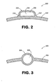
FIG. 2 is a schematic, cross-sectional diagram depicting an exemplary embodiment of an engine casing incorporating an integrated fluid conduit. -
FIG. 3 is a schematic, cross-sectional view of another embodiment of an engine casing incorporating an integrated fluid conduit. - Gas turbine engine systems involving integrated fluid conduits are provided, several exemplary embodiments of which will be described in detail. In this regard, some embodiments incorporate fluid conduits that are integrated with casings of the gas turbine engines. By way of example, a fluid conduit (e.g., a bleed air duct, hydraulic line, or fuel line) can be integrated with an exterior casing of the engine, thereby reducing the overall profile of the engine. In this manner, a nacelle used to protect and mount the gas turbine engine may be reduced in size, thereby promoting aerodynamic efficiency of the nacelle. Notably, by integrating a fluid conduit with a casing, a weight reduction also may be achieved as the casing and conduit may share a wall. Additionally, attachment fixtures conventionally used for securing conduit to the exterior of the casing can be omitted in some embodiments.
- In this regard, reference is made to the exemplary embodiment of
FIG. 1 , which schematically depicts agas turbine engine 100 configured as a turbofan. Although the embodiment ofFIG. 1 is configured as a turbofan, there is no intention to limit the concept described herein to such configurations, as various other configurations of gas turbine engines can be used. - As shown in
FIG. 1 ,engine 100 incorporates afan casing 102, in which a fan (not shown) is mounted. Ahigh pressure casing 104 is mounted aft of the fan casing. Casing 104 houses a compressor section, a combustion section and a turbine section. In the embodiment ofFIG. 1 , two representative examples of fluid conduits are shown integrated into the casings of the engine. Specifically, the embodiment ofFIG. 1 includesconduit 110 andconduit 120. -
Conduit 110 is arbitrarily depicted for routing fluid between a location A (located on the fan casing) and location B (located on the high pressure casing). Specifically,conduit 110 is a multi-segment conduit that incorporatessegments interconnecting segments segments conduit segment 112 extends annularly along a portion of the fan casing, then turns and extends axially along the fan casing and terminates at fitting 115. From fitting 115,segment 113 extends radially inwardly toward the high pressure casing and terminates at fitting 116. Notably,fitting 116 is located at the intersection of the fan casing and the high pressure casing due to manufacturing techniques that form the two casings separately. Thus, it should be understood that integration of a conduit into a casing can accommodate inter-casing runs by using fittings, for example. - Aft of
fitting 116,conduit segment 114 extends axially along the high pressure casing and then turns to extend annularly across a portion of the high pressure casing. Since, in some embodiments,conduit 110 is not formed of tubing that is shaped, e.g., bent, to form the various curves required for routing fluids from location A to location B, less conduit may be required. This is because adherence to tubing bend-radius restrictions need not be followed. - In some embodiments, different materials can be used for conduits and/or conduit segments depending, at least in part, upon the range of temperatures to which the conduits and/or segments are to be exposed. For instance, a different material may be used for a segment that spans a relatively high temperature section of a casing. Notably, in those embodiments in which a fluid is routed through a conduit or conduit segment that is exposed to a temperature that is different from the fluid temperature, the conduit or conduit segment can function as a heat exchanger. In some embodiments, such heat exchange functionality may result in a weight savings as a dedicated or larger heat exchange component need not be used.
- In contrast to
conduit 110, which extends across multiple casings,conduit 120 extends along an exterior of a single casing, i.e., the high pressure casing. In the embodiment ofFIG. 1 ,conduit 120 incorporates multiple segments that are interconnected in a branch structure without the use of intervening fittings. In particular,conduit 120 includessegments segment 128. Notably,segment 128 includes afitting 130 that is used to interconnect with a corresponding fixture of a nacelle, so that fluid (in this case, environmental air) can be provided to the aircraft. - Various techniques can be used for integrating fluid conduit into an exterior of an engine casing. By way of example, representative techniques are depicted schematically in the cross sectional diagrams of
FIGs. 2 and 3 . - As shown in
FIG. 2 ,engine casing 200 incorporates anexterior wall 202. A segment ofconduit 204 useswall 202 to define an interior fluid-routing channel 206. Specifically, fluid-routing channel 206 is defined by aconduit wall 208 andwall 202 of the casing such that the fluid-routing channel is located radially outboard of thewall 202. In this embodiment, terminatingends wall 202 by welding or other attachment methods, such as brazing or soldering. In other embodiments, other integration methods can be used, such as casting the conduit wall and the casing wall together with the channel being created by an expendable core. Notably, in still other embodiments, a complete section of conduit, i.e., conduit that independently defines an interior channel without terminating ends, can be attached directly to a casing without the use of mounting brackets. - As shown in the embodiment of
FIG. 3 ,engine casing 300 incorporates adiscontinuous casing wall 302 that integrates a segment ofconduit 304. In contrast to the embodiment ofFIG. 2 , in which a portion of the casing wall is used for defining a portion of a fluid-routing channel,conduit segment 304 fully defines a fluid-routing channel 306, withconduit segment 304 further forming a structural portion of the casing wall. In some embodiments, such a configuration can be provided by integrally casting the casing and conduit. - Because the conduit is integrated with a casing, vibration induced failures that plague externally mounted conduits can potentially be reduced or eliminated in some embodiments. Design and testing of the conduits also can be simplified by eliminating complex routing issues and natural frequency testing iterations required with external conduits. Additionally, the integrated conduits may improve the heat transfer between the casing and the fluid within the conduit since due to direct proximity.
- It should be emphasized that the above-described embodiments are merely possible examples of implementations set forth for a clear understanding of the principles of this disclosure. Many variations and modifications may be made to the above-described embodiments without departing substantially from the principles of the disclosure. All such modifications and variations are intended to be included herein within the scope of this disclosure and protected by the accompanying claims.
Claims (13)
- A gas turbine engine (100) comprising:an engine casing (102; 104) having an exterior defined, at least in part, by a casing wall; anda fluid conduit (110; 120) integrated into the casing wall.
- An engine casing (200; 300) for a gas turbine engine comprising:a casing wall (202; 302); anda fluid conduit (206; 300) integrated into the casing wall (202; 302).
- The engine or engine casing of claim 1 or 2, wherein:the fluid conduit (206) comprises a conduit wall (208); anda portion of the casing wall (202) and at least a portion of the conduit wall (208) define a fluid-routing channel (206) of the fluid conduit (204).
- The engine or engine casing of any preceding claim, wherein a or the fluid-routing channel (204) is located radially outboard of the casing wall (202).
- The engine or engine casing of any preceding claim, wherein the engine casing is a high pressure casing.
- The engine or engine casing of any of claims 1 to 4, wherein:the engine casing comprises a fan casing (102) and a high pressure casing (104); andthe fluid conduit (110) extends along a portion of the fan casing (102) and a portion of the high pressure casing (104).
- The engine or engine casing of any preceding claim, wherein the fluid conduit (110) has interconnected multiple segments.
- The engine or engine casing of claims 6 and 7, wherein a first (112) of the multiple segments is located only on the fan casing (102) and a second (114) of the multiple segments is located only on the high pressure casing (104).
- The engine or engine casing of claims 7 or 8, wherein:the engine or engine casing further comprises a fitting (115, 116); anda first (112) of the multiple segments is interconnected with a second (113) of the multiple segments using the fitting (115).
- The engine or engine casing of any of claims 7 to 9, wherein at least two (122, 124) of the multiple segments are formed in a branch configuration such that the at least two of the multiple segment interconnect without the use of a fitting.
- The engine or engine casing of any preceding claim, further comprising a fitting (130) operative to interconnect the fluid conduit (120) with another conduit for routing fluid to a component remote from the engine.
- The engine or engine casing of any preceding claim, wherein the fluid conduit (110; 120; 206; 306) is operative to route air.
- The engine or engine casing of any preceding claim, wherein the engine (100) is a turbofan gas turbine engine, or the engine casing is a turbofan gas turbine engine casing.
Applications Claiming Priority (1)
| Application Number | Priority Date | Filing Date | Title |
|---|---|---|---|
| US11/923,105 US8240979B2 (en) | 2007-10-24 | 2007-10-24 | Gas turbine engine systems involving integrated fluid conduits |
Publications (2)
| Publication Number | Publication Date |
|---|---|
| EP2053205A1 true EP2053205A1 (en) | 2009-04-29 |
| EP2053205B1 EP2053205B1 (en) | 2015-05-06 |
Family
ID=40328941
Family Applications (1)
| Application Number | Title | Priority Date | Filing Date |
|---|---|---|---|
| EP20080253458 Active EP2053205B1 (en) | 2007-10-24 | 2008-10-24 | Gas turbine engine systems involving integrated fluid conduits |
Country Status (2)
| Country | Link |
|---|---|
| US (2) | US8240979B2 (en) |
| EP (1) | EP2053205B1 (en) |
Families Citing this family (6)
| Publication number | Priority date | Publication date | Assignee | Title |
|---|---|---|---|---|
| US7784528B2 (en) * | 2006-12-27 | 2010-08-31 | General Electric Company | Heat exchanger system having manifolds structurally integrated with a duct |
| US9410447B2 (en) * | 2012-07-30 | 2016-08-09 | United Technologies Corporation | Forward compartment service system for a geared architecture gas turbine engine |
| GB201306482D0 (en) * | 2013-04-10 | 2013-05-22 | Rolls Royce Plc | Mounting arrangement |
| US10775046B2 (en) * | 2017-10-18 | 2020-09-15 | Rolls-Royce North American Technologies Inc. | Fuel injection assembly for gas turbine engine |
| US11732656B2 (en) | 2021-03-31 | 2023-08-22 | Raytheon Technologies Corporation | Turbine engine with soaring air conduit |
| GB202306498D0 (en) | 2023-05-03 | 2023-06-14 | Rolls Royce Plc | Gas turbine engine |
Citations (4)
| Publication number | Priority date | Publication date | Assignee | Title |
|---|---|---|---|---|
| GB785491A (en) * | 1954-07-19 | 1957-10-30 | Licentia Gmbh | A high-pressure axial flow steam or gas turbine |
| US4268221A (en) * | 1979-03-28 | 1981-05-19 | United Technologies Corporation | Compressor structure adapted for active clearance control |
| FR2534982A1 (en) * | 1982-10-22 | 1984-04-27 | Snecma | Control device for the tolerances of a high-pressure compressor |
| EP1696113A1 (en) * | 2005-02-28 | 2006-08-30 | General Electric Company | Bolt-on radial bleed manifold |
Family Cites Families (22)
| Publication number | Priority date | Publication date | Assignee | Title |
|---|---|---|---|---|
| US3148504A (en) * | 1961-05-04 | 1964-09-15 | Rolls Royce | Gas turbine engines |
| US3623546A (en) * | 1969-11-10 | 1971-11-30 | Avco Corp | Cooling system for an electronic assembly mounted on a gas turbine engine |
| US4155680A (en) * | 1977-02-14 | 1979-05-22 | General Electric Company | Compressor protection means |
| US4412782A (en) * | 1979-03-28 | 1983-11-01 | United Technologies Corporation | Full hoop bleed manifolds for longitudinally split compressor cases |
| US4312185A (en) * | 1980-02-19 | 1982-01-26 | General Electric Company | Low profile fuel injection system |
| US4469596A (en) | 1982-09-27 | 1984-09-04 | Kantor Frederick W | Fluid transport conduit system in equilibrium with its environment |
| US4504030A (en) * | 1982-12-06 | 1985-03-12 | United Technologies Corporation | Cooling means |
| US4790502A (en) | 1988-01-29 | 1988-12-13 | Usui Kokusai Sangyo Kabushiki Kaisha | Clamp for disposing and securing small-diameter pipe |
| US5003773A (en) | 1989-06-23 | 1991-04-02 | United Technologies Corporation | Bypass conduit for gas turbine engine |
| US4971272A (en) | 1989-06-29 | 1990-11-20 | United Technologies Corporation | Structure for positioning a conduit |
| FR2653171B1 (en) * | 1989-10-18 | 1991-12-27 | Snecma | TURBOMACHINE COMPRESSOR CASING PROVIDED WITH A DEVICE FOR DRIVING ITS INTERNAL DIAMETER. |
| US5174110A (en) | 1991-10-17 | 1992-12-29 | United Technologies Corporation | Utility conduit enclosure for turbine engine |
| US5368069A (en) | 1993-05-28 | 1994-11-29 | Eg&G Pressure Science, Inc. | Conduit joint assembly |
| DE9310270U1 (en) | 1993-07-09 | 1994-11-24 | Siemens AG, 80333 München | Connection element for duct sections through which hot flue gas can flow |
| US6487860B2 (en) * | 2000-12-08 | 2002-12-03 | General Electric Company | Turbine engine fuel supply system |
| US20040007651A1 (en) | 2002-04-24 | 2004-01-15 | Innovative Office Products, Inc. | Universal support for electronic devices |
| US6854487B2 (en) | 2003-06-26 | 2005-02-15 | General Electric Company | Fluid conduit wall inhibiting heat transfer and method for making |
| US7941993B2 (en) * | 2003-10-14 | 2011-05-17 | Rolls-Royce Plc | Engine cooling |
| US7506514B2 (en) | 2005-06-30 | 2009-03-24 | United Technologies Corporation | Augmentor fuel conduit bushing |
| US7900438B2 (en) * | 2006-07-28 | 2011-03-08 | General Electric Company | Heat transfer system and method for turbine engine using heat pipes |
| US7784528B2 (en) * | 2006-12-27 | 2010-08-31 | General Electric Company | Heat exchanger system having manifolds structurally integrated with a duct |
| US7901182B2 (en) * | 2007-05-18 | 2011-03-08 | Siemens Energy, Inc. | Near wall cooling for a highly tapered turbine blade |
-
2007
- 2007-10-24 US US11/923,105 patent/US8240979B2/en active Active
-
2008
- 2008-10-24 EP EP20080253458 patent/EP2053205B1/en active Active
-
2012
- 2012-05-07 US US13/465,559 patent/US9611758B2/en active Active
Patent Citations (4)
| Publication number | Priority date | Publication date | Assignee | Title |
|---|---|---|---|---|
| GB785491A (en) * | 1954-07-19 | 1957-10-30 | Licentia Gmbh | A high-pressure axial flow steam or gas turbine |
| US4268221A (en) * | 1979-03-28 | 1981-05-19 | United Technologies Corporation | Compressor structure adapted for active clearance control |
| FR2534982A1 (en) * | 1982-10-22 | 1984-04-27 | Snecma | Control device for the tolerances of a high-pressure compressor |
| EP1696113A1 (en) * | 2005-02-28 | 2006-08-30 | General Electric Company | Bolt-on radial bleed manifold |
Also Published As
| Publication number | Publication date |
|---|---|
| US20120243972A1 (en) | 2012-09-27 |
| EP2053205B1 (en) | 2015-05-06 |
| US20090110537A1 (en) | 2009-04-30 |
| US9611758B2 (en) | 2017-04-04 |
| US8240979B2 (en) | 2012-08-14 |
Similar Documents
| Publication | Publication Date | Title |
|---|---|---|
| US9611758B2 (en) | Gas turbine engine systems involving integrated fluid conduits | |
| US10641128B2 (en) | Gas turbine engine oil tank with integrated packaging configuration | |
| EP4368817B1 (en) | Cooling system for power cables in a gas turbine engine | |
| US8826641B2 (en) | Thermal management system integrated pylon | |
| US20200200034A1 (en) | Shroud Sealing for a Gas Turbine Engine | |
| US20080181770A1 (en) | Aeroengine drain assembly | |
| EP4495410A2 (en) | Turbofan engine having a dimensional relationship between inlet and fan size | |
| US20160161121A1 (en) | Gas turbine engine with ceramic panel | |
| US9328629B2 (en) | Outer case with gusseted boss | |
| EP2085600B1 (en) | Thermal management system integrated pylon | |
| WO2010033414A2 (en) | Exhaust-gas turbocharger | |
| EP2514947A1 (en) | Gas turbine engine including a nacelle assembly which comprises a cavity and a fan containment case | |
| US11415006B2 (en) | CMC vane with support spar and baffle | |
| JP2014206167A (en) | Internal cowl structure for aircraft turbine engines | |
| EP3670865B1 (en) | Attritable engine integrated with vehicle | |
| WO2009024662A3 (en) | Coupling system connecting an internal structure and an external structure of a jet engine nacelle | |
| EP3450696B1 (en) | Segmented conduit with airfoil geometry | |
| CA2581827A1 (en) | Low noise exhaust ducting system | |
| EP3741961A1 (en) | Gas turbine engine accessory gearbox | |
| US9416729B2 (en) | Oil tank mount with yoke | |
| US10662792B2 (en) | Gas turbine engine cooling fluid composite tube | |
| EP2559865B1 (en) | Bearing system for a gas turbine engine and corresponding assembly method | |
| US20200318910A1 (en) | Curved heat exchanger | |
| EP3782911A1 (en) | Engine wing | |
| CN113602506A (en) | Propulsion system, aircraft with a propulsion system and method for producing an aircraft |
Legal Events
| Date | Code | Title | Description |
|---|---|---|---|
| PUAI | Public reference made under article 153(3) epc to a published international application that has entered the european phase |
Free format text: ORIGINAL CODE: 0009012 |
|
| AK | Designated contracting states |
Kind code of ref document: A1 Designated state(s): AT BE BG CH CY CZ DE DK EE ES FI FR GB GR HR HU IE IS IT LI LT LU LV MC MT NL NO PL PT RO SE SI SK TR |
|
| AX | Request for extension of the european patent |
Extension state: AL BA MK RS |
|
| 17P | Request for examination filed |
Effective date: 20090605 |
|
| 17Q | First examination report despatched |
Effective date: 20090720 |
|
| AKX | Designation fees paid |
Designated state(s): DE GB |
|
| GRAP | Despatch of communication of intention to grant a patent |
Free format text: ORIGINAL CODE: EPIDOSNIGR1 |
|
| INTG | Intention to grant announced |
Effective date: 20150123 |
|
| GRAS | Grant fee paid |
Free format text: ORIGINAL CODE: EPIDOSNIGR3 |
|
| GRAA | (expected) grant |
Free format text: ORIGINAL CODE: 0009210 |
|
| AK | Designated contracting states |
Kind code of ref document: B1 Designated state(s): DE GB |
|
| REG | Reference to a national code |
Ref country code: GB Ref legal event code: FG4D |
|
| REG | Reference to a national code |
Ref country code: DE Ref legal event code: R096 Ref document number: 602008038027 Country of ref document: DE Effective date: 20150618 |
|
| REG | Reference to a national code |
Ref country code: DE Ref legal event code: R097 Ref document number: 602008038027 Country of ref document: DE |
|
| PLBE | No opposition filed within time limit |
Free format text: ORIGINAL CODE: 0009261 |
|
| STAA | Information on the status of an ep patent application or granted ep patent |
Free format text: STATUS: NO OPPOSITION FILED WITHIN TIME LIMIT |
|
| 26N | No opposition filed |
Effective date: 20160209 |
|
| REG | Reference to a national code |
Ref country code: DE Ref legal event code: R082 Ref document number: 602008038027 Country of ref document: DE Representative=s name: SCHMITT-NILSON SCHRAUD WAIBEL WOHLFROM PATENTA, DE |
|
| REG | Reference to a national code |
Ref country code: DE Ref legal event code: R082 Ref document number: 602008038027 Country of ref document: DE Representative=s name: SCHMITT-NILSON SCHRAUD WAIBEL WOHLFROM PATENTA, DE Ref country code: DE Ref legal event code: R081 Ref document number: 602008038027 Country of ref document: DE Owner name: UNITED TECHNOLOGIES CORP. (N.D.GES.D. STAATES , US Free format text: FORMER OWNER: UNITED TECHNOLOGIES CORPORATION, HARTFORD, CONN., US |
|
| REG | Reference to a national code |
Ref country code: DE Ref legal event code: R081 Ref document number: 602008038027 Country of ref document: DE Owner name: RAYTHEON TECHNOLOGIES CORPORATION (N.D.GES.D.S, US Free format text: FORMER OWNER: UNITED TECHNOLOGIES CORP. (N.D.GES.D. STAATES DELAWARE), FARMINGTON, CONN., US Ref country code: DE Ref legal event code: R081 Ref document number: 602008038027 Country of ref document: DE Owner name: RTX CORPORATION (N.D.GES.D. STAATES DELAWARE),, US Free format text: FORMER OWNER: UNITED TECHNOLOGIES CORP. (N.D.GES.D. STAATES DELAWARE), FARMINGTON, CONN., US |
|
| P01 | Opt-out of the competence of the unified patent court (upc) registered |
Effective date: 20230519 |
|
| PGFP | Annual fee paid to national office [announced via postgrant information from national office to epo] |
Ref country code: GB Payment date: 20250923 Year of fee payment: 18 |
|
| REG | Reference to a national code |
Ref country code: DE Ref legal event code: R081 Ref document number: 602008038027 Country of ref document: DE Owner name: RTX CORPORATION (N.D.GES.D. STAATES DELAWARE),, US Free format text: FORMER OWNER: RAYTHEON TECHNOLOGIES CORPORATION (N.D.GES.D.STAATES DELAWARE), ARLINGTON, VA, US |
|
| PGFP | Annual fee paid to national office [announced via postgrant information from national office to epo] |
Ref country code: DE Payment date: 20250923 Year of fee payment: 18 |