EP2053104B1 - Strahlungshärtbare Tintenstrahldruckverfahren - Google Patents
Strahlungshärtbare Tintenstrahldruckverfahren Download PDFInfo
- Publication number
- EP2053104B1 EP2053104B1 EP07119374.2A EP07119374A EP2053104B1 EP 2053104 B1 EP2053104 B1 EP 2053104B1 EP 07119374 A EP07119374 A EP 07119374A EP 2053104 B1 EP2053104 B1 EP 2053104B1
- Authority
- EP
- European Patent Office
- Prior art keywords
- radiation curable
- curable inkjet
- ink
- inkjet printing
- printing method
- Prior art date
- Legal status (The legal status is an assumption and is not a legal conclusion. Google has not performed a legal analysis and makes no representation as to the accuracy of the status listed.)
- Not-in-force
Links
- 0 CC(C(C1=CCCC=C1)=O)=*OC(c1ccccc1)=O Chemical compound CC(C(C1=CCCC=C1)=O)=*OC(c1ccccc1)=O 0.000 description 1
Images


Classifications
-
- B—PERFORMING OPERATIONS; TRANSPORTING
- B41—PRINTING; LINING MACHINES; TYPEWRITERS; STAMPS
- B41J—TYPEWRITERS; SELECTIVE PRINTING MECHANISMS, i.e. MECHANISMS PRINTING OTHERWISE THAN FROM A FORME; CORRECTION OF TYPOGRAPHICAL ERRORS
- B41J11/00—Devices or arrangements of selective printing mechanisms, e.g. ink-jet printers or thermal printers, for supporting or handling copy material in sheet or web form
- B41J11/0015—Devices or arrangements of selective printing mechanisms, e.g. ink-jet printers or thermal printers, for supporting or handling copy material in sheet or web form for treating before, during or after printing or for uniform coating or laminating the copy material before or after printing
- B41J11/002—Curing or drying the ink on the copy materials, e.g. by heating or irradiating
- B41J11/0021—Curing or drying the ink on the copy materials, e.g. by heating or irradiating using irradiation
- B41J11/00214—Curing or drying the ink on the copy materials, e.g. by heating or irradiating using irradiation using UV radiation
-
- B—PERFORMING OPERATIONS; TRANSPORTING
- B41—PRINTING; LINING MACHINES; TYPEWRITERS; STAMPS
- B41M—PRINTING, DUPLICATING, MARKING, OR COPYING PROCESSES; COLOUR PRINTING
- B41M5/00—Duplicating or marking methods; Sheet materials for use therein
- B41M5/0041—Digital printing on surfaces other than ordinary paper
- B41M5/0047—Digital printing on surfaces other than ordinary paper by ink-jet printing
-
- B—PERFORMING OPERATIONS; TRANSPORTING
- B41—PRINTING; LINING MACHINES; TYPEWRITERS; STAMPS
- B41M—PRINTING, DUPLICATING, MARKING, OR COPYING PROCESSES; COLOUR PRINTING
- B41M5/00—Duplicating or marking methods; Sheet materials for use therein
- B41M5/0041—Digital printing on surfaces other than ordinary paper
- B41M5/0064—Digital printing on surfaces other than ordinary paper on plastics, horn, rubber, or other organic polymers
-
- B—PERFORMING OPERATIONS; TRANSPORTING
- B41—PRINTING; LINING MACHINES; TYPEWRITERS; STAMPS
- B41M—PRINTING, DUPLICATING, MARKING, OR COPYING PROCESSES; COLOUR PRINTING
- B41M7/00—After-treatment of prints, e.g. heating, irradiating, setting of the ink, protection of the printed stock
- B41M7/0081—After-treatment of prints, e.g. heating, irradiating, setting of the ink, protection of the printed stock using electromagnetic radiation or waves, e.g. ultraviolet radiation, electron beams
-
- C—CHEMISTRY; METALLURGY
- C09—DYES; PAINTS; POLISHES; NATURAL RESINS; ADHESIVES; COMPOSITIONS NOT OTHERWISE PROVIDED FOR; APPLICATIONS OF MATERIALS NOT OTHERWISE PROVIDED FOR
- C09D—COATING COMPOSITIONS, e.g. PAINTS, VARNISHES OR LACQUERS; FILLING PASTES; CHEMICAL PAINT OR INK REMOVERS; INKS; CORRECTING FLUIDS; WOODSTAINS; PASTES OR SOLIDS FOR COLOURING OR PRINTING; USE OF MATERIALS THEREFOR
- C09D11/00—Inks
- C09D11/02—Printing inks
- C09D11/10—Printing inks based on artificial resins
- C09D11/101—Inks specially adapted for printing processes involving curing by wave energy or particle radiation, e.g. with UV-curing following the printing
-
- C—CHEMISTRY; METALLURGY
- C09—DYES; PAINTS; POLISHES; NATURAL RESINS; ADHESIVES; COMPOSITIONS NOT OTHERWISE PROVIDED FOR; APPLICATIONS OF MATERIALS NOT OTHERWISE PROVIDED FOR
- C09D—COATING COMPOSITIONS, e.g. PAINTS, VARNISHES OR LACQUERS; FILLING PASTES; CHEMICAL PAINT OR INK REMOVERS; INKS; CORRECTING FLUIDS; WOODSTAINS; PASTES OR SOLIDS FOR COLOURING OR PRINTING; USE OF MATERIALS THEREFOR
- C09D11/00—Inks
- C09D11/30—Inkjet printing inks
- C09D11/36—Inkjet printing inks based on non-aqueous solvents
Definitions
- the present invention relates to radiation curable inkjet printing of materials suitable for making flexible foils and plastic bags.
- flexography an image is printed using a mirrored master of the required image as a 3D relief in a rubber or polymer material.
- a measured amount of ink is deposited upon the surface of the printing plate or printing cylinder. This print surface then contacts the substrate whereby the ink is transferred.
- Generally cylinders using flexographic printing sleeves are used for reasons of productivity.
- Plastic bags have been printed by flexography for many years.
- US 4529087 (MAINE POLY INC.) discloses the production of antistatic plastic bags including a printing step of a polyethylene substrate with a flexographic printing press.
- tiny drops of ink fluid are projected directly onto an ink-receiver surface without physical contact between the printing device and the ink-receiver.
- the printing device stores the printing data electronically and controls a mechanism for ejecting the drops image-wise. Printing is accomplished by moving a printhead across the ink-receiver or vice versa or both.
- the ink When jetting the inkjet ink onto an ink-receiver, the ink typically includes a liquid vehicle and one or more solids, such as dyes, pigments and polymers.
- solids such as dyes, pigments and polymers.
- Ink compositions can be roughly divided in:
- ink compositions are more suitable for an absorbing ink-receiver, whereas hot melt inks and UV-curable inks can also be printed on non-absorbing ink-receivers. Due to thermal requirements posed by hot melt inks on the substrates, especially radiation curable inks have gained the interest of the industry in inkjet printing applications.
- WO 03/044106 discloses single pass inkjet printing methods wherein radiation curable inks are cured on a substrate wherein the region close to the substrate surface is depleted of oxygen.
- Radiation curable inkjet printing has, to our knowledge, not been used for manufacturing plastic bags although it may have been suggested.
- reasons for not introducing inkjet printing for manufacturing plastic bags can be given and include lower printing speed compared to flexography, adhesion problems, lower flexibility of inks, etc.
- inkjet printing is capable of variable data printing and no real limitations in imagesize exist, it allows personalized printed bags of different sizes. It would be desirable to be able to print images by inkjet printing onto plastic bag substrates, such as thin film polyethylene, exhibiting none of the above problems or at least to a lesser extent.
- Objects of the present invention are realized with a radiation curable inkjet printing method as defined by claim 1.
- die as used in disclosing the present invention, means a colorant having a solubility of 10 mg/L or more in the medium in which it is applied and under the ambient conditions pertaining.
- pigment is defined in DIN 55943, herein incorporated by reference, as a colorant that is practically insoluble in the application medium under the pertaining ambient conditions, hence having a solubility of less than 10 mg/L therein.
- alkyl means all variants possible for each number of carbon atoms in the alkyl group i.e. for three carbon atoms: n-propyl and isopropyl; for four carbon atoms: n-butyl, isobutyl and tertiary-butyl; for five carbon atoms: n-pentyl, 1,1-dimethyl-propyl, 2,2-dimethylpropyl and 2-methyl-butyl etc.
- actinic radiation means electromagnetic radiation capable of initiating photochemical reactions.
- electromagnetic radiation means electromagnetic radiation in the wavelength range of about 100 to about 400 nanometers.
- Dynamic mechanical analysis is a technique used to characterize the viscoelastic nature of polymers.
- the method most commonly used today employs forced oscillation. Forced oscillations involve the continued application of a force to the sample. An oscillating force is applied to a sample of material and the resulting displacement of the sample is measured. Solids are tested in a film tension clamp geometry. The sample deforms under the applied strain. From this the stiffness of the sample can be determined, and the sample modulus can be calculated. The modulus is split into the storage modulus, E', i.e. a measure of the energy stored during a cycle, and the loss modulus, E", i.e. a measure of the energy lost.
- E' storage modulus
- E loss modulus
- the loss modulus E" has a maximum at the glass transition of the polymer, where it softens from a glassy to a rubbery state taken into account the thickness of the sample.
- the Tan ⁇ is equal to the ratio E"/E' or loss modulus divided by storage modulus. The smaller the Tan ⁇ , the more viscous the material.
- the radiation curable inkjet printing method for producing printed plastic bags according to the present invention comprises the steps of:
- the surface temperature of the polymeric substrate during in radiation curable inkjet printing method according to the present invention is preferably in the range of 50 to 100°C, more preferably between 70 and 80°C.
- the radiation curable inkjet printing method according to the present invention uses as a pigmented radiation curable inkjet ink as the radiation curable liquid.
- a pigmented radiation curable inkjet ink is printed on the radiation curable liquid.
- the surface tension of the pigmented radiation curable inkjet ink is not more than 5 mN/m smaller than the surface tension of the radiation curable liquid.
- the radiation curable inkjet printing method according to the present invention includes a corona treatment of the substrate.
- Any polymeric substrate having a maximum value for Tan ⁇ between 40°C and 110°C is suitable as web-like polymeric substrate for use in the present invention.
- plastic shopping bags are most often made of polyethylene.
- Polyethylene is the most preferred polymeric substrate for use as web-like polymeric substrate in the present invention.
- Polyethylene is produced in various low and high densities. These are well-known to a skilled person in manufacturing polyethylene films and foils by their abbreviations, such as UHMWPE, HDPE, PEX, MDPE, LLDPE, LDPE and VLDPE. The latter three are most commonly used for making plastic bags.
- LLDPE is defined by a density between 0.915 and 0.925 g/cm 3 and is a substantially linear polymer, with significant numbers of short branches, commonly made by copolymerization of ethylene with short-chain alphaolefins (e.g. 1-butene, 1-hexene, and 1-octene). LLDPE has higher tensile strength than LDPE and exhibits higher impact and puncture resistance than LDPE.
- LDPE is defined by a density between 0.910 and 0.940 g/cm 3 .
- LDPE has a high degree of short and long chain branching, which means that the chains do not pack into the crystal structure as well. It has therefore less strong intermolecular forces as the instantaneous-dipole induced-dipole attraction is less. This results in a lower tensile strength and increased ductility.
- LDPE is created by free radical polymerization. The high degree of branches with long chains gives molten LDPE unique and desirable flow properties.
- VLDPE is defined by a density between 0.880 and 0.915 g/cm 3 and is a substantially linear polymer, with high levels of short chain branches, commonly made by copolymerization of ethylene with short-chain alphaolefins (e.g. 1-butene, 1-hexene, and 1-octene). VLDPE is most commonly produced using metallocene catalysts due to the greater co-monomer incorporation exhibited by these catalysts
- the polymeric substrates for use as web-like polymeric substrate in the present invention are preferably selected from the group consisting of LLDPE, LDPE and VLDPE. Most preferably the polymeric substrate for use as web-like polymeric substrate in the present invention is LDPE.
- the thickness of the polymeric substrate depends on the specific application. For plastic bags, preferably a thickness between 30 and 200 ⁇ m, more preferably between 50 and 100 ⁇ m and most preferably between 60 to 80 ⁇ m is used.
- a primer layer is applied to the polymeric substrate for creating a specific effect such as a glossy or a mat finish.
- the dry thickness is less than 5 ⁇ m, preferably less than 3 ⁇ m, these primers have no influence on the invention. If the inkjet printing is performed in a wet on wet fashion, i.e. without intermediate curing, it was observed that aqueous primers cannot be used.
- the primer used in the invention is a non-aqueous primer.
- the primer can be applied beforehand, for example, as a continuous layer by coating or flexographic printing.
- the primer is a non-aqueous radiation curable liquid. Then it becomes also possible to jet this radiation curable liquid prior to jetting the inkjet inks using the same single pass inkjet printer.
- Each polymeric substrate has a specific surface energy. This surface energy can be raised by a surface treatment.
- Corona treatment is the standard surface treatment method in the plastic filmconverting industry, because it is safe, economical, and delivers high line speed throughput.
- plastics such as polyethylene and polypropylene, have chemically inert and nonporous surfaces leading to a low surface energy.
- Corona discharge equipment consists of a high-frequency power generator, a high-voltage transformer, a stationary electrode, and a treater ground roll. Standard utility electrical power is converted into higher frequency power which is then supplied to the treater station. The treater station applies this power through ceramic or metal electrodes over an air gap onto the material's surface.
- pre-treatment Generally it is observed that all substrates provide a better bonding surface when they are treated at the time they are produced. This is called “pre-treatment.” The effects of corona treatment diminish over time. Therefore many surfaces will require a second “bump” treatment at the time they are converted to ensure bonding with printing inks, coatings, and adhesives.
- a corona treatment can be applied in the present invention to the unprimed substrate, but also to the primed substrate.
- the radiation curable liquids and inks may be jetted by one or more printing heads ejecting small droplets of ink in a controlled manner through nozzles onto an ink-receiving surface, which is moving relative to the printing head(s).
- a preferred printhead for the inkjet printing system is a piezoelectric head.
- Piezoelectric inkjet printing is based on the movement of a piezoelectric ceramic transducer when a voltage is applied thereto. The application of a voltage changes the shape of the piezoelectric ceramic transducer in the printhead creating a void, which is then filled with ink. When the voltage is again removed, the ceramic expands to its original shape, ejecting a drop of ink from the print head.
- the inkjet printing method according to the present invention is not restricted to piezoelectric inkjet printing.
- Other inkjet printing heads can be used and include various types, such as a continuous type and thermal, electrostatic and acoustic drop on demand type.
- the inks must be ejected readily from the printing heads, which puts a number of constraints on the physical properties of the ink, e.g. a low viscosity at the jetting temperature, which may vary from 25°C to 110°C, a surface energy such that the printhead nozzle can form the necessary small droplets, a homogenous ink capable of rapid conversion to a dry printed area, etc.
- a low viscosity at the jetting temperature which may vary from 25°C to 110°C
- a surface energy such that the printhead nozzle can form the necessary small droplets
- a homogenous ink capable of rapid conversion to a dry printed area etc.
- the inkjet printhead scans back and forth in a transversal direction across the moving ink-receiver surface.
- the curing means are most often attached to both sides of the printhead. Printing in such a manner at high speed, the curing means does not cause any significant warm-up of the substrate surface.
- a single pass printing process the printing is accomplished by using page wide inkjet printing heads or multiple staggered inkjet printing heads which cover the entire width of the ink-receiver surface.
- the inkjet printing heads remain stationary and the ink-receiver surface is transported under the inkjet printing head(s). All curable liquids and inks have then to be cured instanteously downstream of the printing area by a radiation curing means.
- This radiation curing means requires usually high power UV lamps also producing a large amount of heat which usually is removed by ventilation or water cooling.
- the heat produced by the radiation curing means is preferably used to increase the surface temperature of the substrate.
- the single pass inkjet printer according to the present invention comprises
- the heat for increasing the surface temperature of the substrate is delivered by the curing means.
- the substrate can also be heated by e.g. a heated drum, but usually this poses large difficulties for realizing a reliable transport of a a web-like polymeric substrate having a maximum value for Tan ⁇ between 40°C and 110°C
- Curable liquids and inks according to the present invention are cured by exposing them to actinic radiation.
- the curable liquids and inks comprise a photoinitiator which allows radiation curing preferably by ultraviolet radiation.
- a static fixed radiation source is employed.
- the source of radiation arranged is preferably an elongated radiation source extending transversely across the ink-receiver surface to be cured and adjacent to the transverse path of the printhead so that the subsequent rows of images formed by the printhead are passed, stepwise or continually, beneath that radiation source. At least part of the radiation emitted is absorbed by the photo-initiator or photo-initiator system.
- UV radiation including a high or low pressure mercury lamp, a cold cathode tube, a black light, an ultraviolet LED, an ultraviolet laser, and a flash light.
- the preferred source is one exhibiting a relatively long wavelength UV-contribution having a dominant wavelength of 300-400 nm.
- a UV-A light source is preferred due to the reduced light scattering therewith resulting in more efficient interior curing.
- UV radiation is generally classed as UV-A, UV-B, and UV-C as follows:
- the first UV-source can be selected to be rich in UV-C, in particular in the range of 260 nm-200 nm.
- the second UV-source can then be rich in UV-A, e.g. a gallium-doped lamp, or a different lamp high in both UV-A and UV-B.
- the first UV-source can be selected to be rich in UV-A, e.g. a lead-doped lamp and the second UV-source can then be rich in UV-C, e.g. a non-doped lamp.
- the use of two UV-sources has been found to have advantages e.g. a fast curing speed.
- a radiation source is chosen capable of producing enough heat to invoke on the polymeric substrate, a surface temperature preferably at least 50°C and up to 100°C.
- the inkjet printer often includes one or more oxygen depletion units.
- the oxygen depletion units place a blanket of nitrogen or other relatively inert gas (e.g. CO 2 ), with adjustable position and adjustable inert gas concentration, in order to reduce the oxygen concentration in the curing environment. Residual oxygen levels are usually maintained as low as 200 ppm, but are generally in the range of 200 ppm to 1200 ppm.
- the curable liquids and inks used in the radiation curable printing method according to the present invention is preferably a UV radiation curable inkjet liquid or ink.
- the curable liquids and inks preferably comprise at least one photoinitiator.
- the curable liquids and inks are preferably part of an inkjet ink set comprising at least one ink containing one or more colorants, preferably one or more colour pigments.
- the curable inkjet ink set preferably comprises at least one yellow curable inkjet ink (Y), at least one cyan curable inkjet ink (C) and at least one magenta curable inkjet ink (M) and preferably also at least one black curable inkjet ink (K).
- the curable CMYK inkjet ink set may also be extended with extra inks such as red, green, blue, and/or orange to further enlarge the colour gamut of the image.
- the CMYK ink set may also be extended by the combination of full density and light density inks of both colour inks and/or black inks to improve the image quality by lowered graininess.
- the curable liquid or ink may further also contain at least one inhibitor.
- the curable liquid or ink may further also contain at least one surfactant.
- the curable liquid or ink is a non-aqueous inkjet liquid or ink.
- non-aqueous refers to a liquid carrier which should contain no water. However sometimes a small amount, generally less than 5 wt% of water based on the total weight of the ink, can be present. This water was not intentionally added but came into the formulation via other components as a contamination, such as for example polar organic solvents. Higher amounts of water than 5 wt% tend to make the non-aqueous inkjet inks instable, preferably the water content is less than 1 wt% based on the total weight dispersion medium and most preferably no water at all is present.
- the curable liquid or ink preferably does not contain an evaporable component such as an organic solvent. But sometimes it can be advantageous to incorporate a small amount of an organic solvent to improve adhesion to the surface of a substrate after UV-curing.
- the added solvent can be any amount in the range that does not cause problems of solvent resistance and VOC, and preferably 0.1-10.0 wt%, and particularly preferably 0.1-5.0 wt%, each based on the total weight of the curable ink.
- the pigmented curable ink preferably contains a dispersant, more preferably a polymeric dispersant, for dispersing the pigment.
- the pigmented curable ink may contain a dispersion synergist to improve the dispersion quality of the ink.
- at least the magenta ink contains a dispersion synergist.
- a mixture of dispersion synergists may be used to further improve dispersion stability.
- the viscosity of the ink is preferably smaller than 100 mPa.s at 30°C and at a shear rate of 100 s -1 .
- the viscosity of the inkjet ink is preferably smaller than 30 mPa.s, more preferably lower than 15 mPa.s, and most preferably between 2 and 10 mPa.s at a shear rate of 100 s -1 and a jetting temperature between 10 and 70°C.
- the polymerizable compounds used in the curable ink, especially for food packaging applications are preferably purified compounds having no or almost no impurities, more particularly no toxic or carcinogenic impurities.
- the impurities are usually derivative compounds obtained during synthesis of the polymerizable compound. Sometimes, however, some compounds may be added deliberately to pure polymerizable compounds in harmless amounts, for example, polymerization inhibitors or stabilizers.
- the curable liquids and inks used in the radiation curable printing method according to the present invention preferably contain a photoinitiator or photoinitiator system such as, for example, one or more photoinitiators and one or more co-initiators.
- the photoinitiator or photoinitiator system absorbs light and is responsible for the production of initiating species, i.e. free radicals which induce the polymerization of monomers, oligomers and polymers and with polyfunctional monomers and oligomers thereby also induce cross-linking.
- Irradiation with actinic radiation may be realized in two steps by changing wavelength or intensity. In such cases it is preferred to use 2 types of photoinitiator together.
- Free radical photoinitiators can act as a Norrish type I or a Norrish type II initiator.
- Tertiary amines are today admixed to free radical polymerizable radiation curable formulations for two main reasons:
- a suitable Norrish type I-photoinitiator is selected from the group consisting of benzoinethers, benzil ketals, ⁇ , ⁇ -dialkoxyacetophenones, ⁇ -hydroxyalkylphenones, ⁇ -aminoalkylphenones, acylphosphine oxides, acylphosphine sulphides, ⁇ -haloketones, ⁇ -halosulfones and phenylglyoxalates.
- a suitable Norrish type II-initiator is selected from the group consisting of benzophenones, thioxanthones, 1,2-diketones and anthraquinones.
- photoinitiators suitable for the photoinitiating functional groups in preparing diffusion hindered photoinitiators are disclosed by CRIVELLO, J.V., et al.; Chemistry & technology of UV & EB Formulation for Coatings, Inks & Paints. Volume III: Photoinitiators for Free Radical, Cationic & Anionic Photopolymerisation, 2nd edition, John Wiley & Sons Ltd in association with SITA Technology Ltd, London, UK, 1998 edited by Dr. G. Bradley; ISBN 0471 978922, page 287 - 294 .
- photo-initiators may include, but are not limited to, the following compounds or combinations thereof: benzophenone and substituted benzophenones, 1-hydroxycyclohexyl phenyl ketone, thioxanthones such as isopropylthioxanthone, 2-hydroxy-2-methyl-1-phenylpropan-1-one, 2-benzyl-2-dimethylamino- (4-morpholinophenyl) butan-1-one, benzil dimethylketal, bis (2,6- dimethylbenzoyl) -2,4, 4-trimethylpentylphosphine oxide, 2,4,6trimethylbenzoyldiphenylphosphine oxide, 2-methyl-1- [4- (methylthio) phenyl] -2-morpholinopropan-1-one, 2,2-dimethoxy-1, 2-diphenylethan-1-one or 5,7-diiodo-3- butoxy-6-fluorone, diphenyliodonium fluoride and trip
- Suitable commercial photo-initiators include IrgacureTM 184, IrgacureTM 500, IrgacureTM 907, IrgacureTM 369, IrgacureTM 1700, IrgacureTM 651, IrgacureTM 819, IrgacureTM 1000, IrgacureTM 1300, IrgacureTM 1870, DarocurTM 1173, DarocurTM 2959, DarocurTM 4265 and DarocurTM ITX available from CIBA SPECIALTY CHEMICALS, Lucerin TPO available from BASF AG, EsacureTM KT046, EsacureTM KIP150, EsacureTM KT37 and EsacureTM EDB available from LAMBERTI, H-NuTM 470 and H-NuTM 470X available from SPECTRA GROUP Ltd..
- Suitable cationic photo-initiators include compounds, which form aprotic acids or Bronstead acids upon exposure to ultraviolet and/or visible light sufficient to initiate polymerization.
- the photo-initiator used may be a single compound, a mixture of two or more active compounds, or a combination of two or more different compounds, i.e. co-initiators.
- suitable cationic photo-initiators are aryldiazonium salts, diaryliodonium salts, triarylsulphonium salts, triarylselenonium salts and the like.
- the curable inkjet liquids and inks may additionally contain co-initiators.
- co-initiators for example, the combination of titanocenes and trichloromethyl-s-triazines, of titanocenes and ketoxime ethers and of acridines and trichloromethyl-s-triazines is known.
- a further increase in sensitivity can be achieved by adding dibenzalacetone or amino acid derivatives.
- the amount of co-initiator or co-initiators is in general from 0.01 to 20 wt%, preferably from 0.05 to 10 wt%, based in each case on the total weight of the curable inkjet ink.
- Suitable examples of co-initiators can be categorized in 4 groups:
- the preferred co-initiators are aminobenzoates.
- the curable inkjet liquids and inks may contain a photo-initiator system containing one or more photo-initiators and one or more sensitizers that transfer energy to the photo-initiator(s).
- Suitable sensitizers include photoreducible xanthene, fluorene, benzoxanthene, benzothioxanthene, thiazine, oxazine, coumarin, pyronine, porphyrin, acridine, azo, diazo, cyanine, merocyanine, diarylmethyl, triarylmethyl, anthraquinone, phenylenediamine, benzimidazole, fluorochrome, quinoline, tetrazole, naphthol, benzidine, rhodamine, indigo and/or indanthrene dyes.
- the amount of the sensitizer is in general from 0.01 to 15 wt%, preferably from 0.05 to 5 w
- a preferred initiator system is 2,2'-bis(o-chlorophenyl)-4,4',5,5'-tetraphenyl-(7CI,8CI) 4,4'-Bi-4H-imidazole corresponding to the chemical formula:
- Another preferred type of initiator is an oxime ester.
- a suitable example has as chemical formula:
- a preferred amount of initiator is 0.3 - 50 wt% of the total weight of the curable liquid, and more preferably 1 - 15 wt% of the total weight of the curable pigment inkjet ink.
- Irradiation with actinic radiation may be realized in two steps by changing wavelength or intensity. In such cases it is preferred to use 2 types of photo-initiator together.
- the curable liquids and inks used in the radiation curable printing method according to the present invention may contain a polymerization inhibitor.
- Suitable polymerization inhibitors include phenol type antioxidants, hindered amine light stabilizers, phosphor type antioxidants, hydroquinone monomethyl ether commonly used in (meth)acrylate monomers, and hydroquinone, t-butylcatechol, pyrogallol, 2,6-di-tert.butyl-4-methylphenol may also be used.
- Suitable commercial inhibitors are, for example, SumilizerTM GA-80, SumilizerTM GM and SumilizerTM GS produced by Sumitomo Chemical Co. Ltd.; GenoradTM 16, GenoradTM 18 and GenoradTM 20 from Rahn AG; IrgastabTM UV10 and IrgastabTM UV22, TinuvinTM 460 and CGS20 from Ciba Specialty Chemicals; FloorstabTM UV range (UV-1, UV-2, UV-5 and UV-8) from Kromachem Ltd, AdditolTM S range (S100, S110, S120 and S130) from Cytec Surface Specialties.
- the inhibitor is preferably a polymerizable inhibitor.
- the amount capable of preventing polymerization is determined prior to blending.
- the amount of a polymerization inhibitor is preferably lower than 5 wt%, more preferably lower than 3 wt% of the total ink or liquid.
- the curable liquids and inks used in the radiation curable printing method according to the present invention may contain a surfactant.
- the surfactant(s) can be anionic, cationic, non-ionic, or zwitter-ionic and are usually added in a total quantity less than 20 wt% based on the total weight of the inkjet ink and particularly in a total less than 10 wt% based on the total weight of the inkjet ink.
- Suitable surfactants include fluorinated surfactants, fatty acid salts, ester salts of a higher alcohol, alkylbenzene sulphonate salts, sulphosuccinate ester salts and phosphate ester salts of a higher alcohol (for example, sodium dodecylbenzenesulphonate and sodium dioctylsulphosuccinate), ethylene oxide adducts of a higher alcohol, ethylene oxide adducts of an alkylphenol, ethylene oxide adducts of a polyhydric alcohol fatty acid ester, and acetylene glycol and ethylene oxide adducts thereof (for example, polyoxyethylene nonylphenyl ether, and SURFYNOLTM 104, 104H, 440, 465 and TG available from AIR PRODUCTS & CHEMICALS INC.).
- preferred surfactants are selected from fluoro surfactants (such as fluorinated hydrocarbons) and silicone surfactants.
- the silicones are typically siloxanes and can be alkoxylated, polyether modified, polyether modified hydroxy functional, amine modified, epoxy modified and other modifications or combinations thereof.
- Preferred siloxanes are polymeric, for example polydimethylsiloxanes.
- a fluorinated or silicone compound may be used as a surfactant, however, a cross-linkable surfactant would be preferred. It is therefore preferred to use a copolymerizable monomer having surface-active effects, for example, polyacrylate copolymers, silicone modified acrylates, silicone modified methacrylates, acrylated siloxanes, polyether modified acrylic modified siloxanes, fluorinated acrylates, and fluorinated methacrylates; these acrylates can be mono-, di-, tri- or higher functional (meth)acrylates.
- Surfactants are known for use in inkjet inks to reduce the surface tension of the ink and to reduce the contact angle on the substrate, i.e. to improve the wetting of the substrate by the ink.
- the jettable fluid must meet stringent performance criteria in order to be adequately jettable with high precision, reliability and during an extended period of time.
- the surface tension of the ink is reduced by the addition of one or more surfactants.
- the surface tension of the inkjet ink is not only determined by the amount and type of surfactant, but also by the polymerizable compounds, the polymeric dispersants and other additives in the ink composition.
- a surfactant can be used with a high, low or intermediate dynamic surface tension.
- Silicone surfactants are generally known to have low dynamic surface tensions while fluorinated surfactants are known to have higher dynamic surface tensions.
- fluorinated surfactants are for example the ZonylTM range of fluoro-surfactants from DUPONT and the FluoradTM range of fluoro-surfactants from 3M.
- fluorinated surfactants are e.g. described in EP 1412438 A (3M).
- Silicone surfactants are often preferred in curable inkjet inks, especially the reactive silicone surfactants, which are able to be polymerized together with the polymerizable compounds during the curing step.
- silicone surfactants are often polysiloxane surfactants, especially polyether modified polysiloxanes, preferably with one or more acrylate function in order to become polymerizable.
- Examples of useful commercial silicone surfactants are those supplied by BYK CHEMIE GMBH (including BykTM-302, 307, 310, 331, 333, 341, 345, 346, 347, 348, UV3500, UV3510 and UV3530), those supplied by TEGO CHEMIE SERVICE (including Tego RadTM 2100, 2200N, 2250, 2300, 2500, 2600 and 2700), EbecrylTM 350 a polysilixone diacrylate and EbecrylTM 1360 a polysiloxane hexaacrylate from CYTEC INDUSTRIES BV and EfkaTM-3000 series (including EfkaTM-3232 and EfkaTM-3883) from EFKA CHEMICALS B.V..
- the curable inks used in the radiation curable printing method according to the present invention preferably may contain a colorant.
- Colorants used in the curable inks may be dyes, pigments or a combination thereof.
- Organic and/or inorganic pigments may be used.
- the colorant is preferably a pigment or a polymeric dye, most preferably a pigment.
- the pigments may be black, white, cyan, magenta, yellow, red, orange, violet, blue, green, brown, mixtures thereof, and the like.
- This colour pigment may be chosen from those disclosed by HERBST, Willy, et al. Industrial Organic Pigments, Production, Properties, Applications. 3rd edition. Wiley - VCH, 2004. ISBN 3527305769 .
- Particular preferred pigments are C.I. Pigment Yellow 1, 3, 10, 12, 13, 14, 17, 55, 65, 73, 74, 75, 83, 93, 97, 109, 111, 120, 128, 138, 139, 150, 151, 154, 155, 175, 180, 181, 185, 194 and 213.
- Particular preferred pigments are C.I. Pigment Red 17, 22, 23, 41, 48:1, 48:2, 49:1, 49:2, 52:1, 57:1, 81:1, 81:3, 88, 112, 122, 144, 146, 149, 169, 170, 175, 176, 184, 185, 188, 202, 206, 207, 210, 216, 221, 248, 251, 254, 255, 264, 266, 270 and 272.
- Particular preferred pigments are C.I. Pigment Violet 1, 2, 19, 23, 32, 37 and 39.
- Particular preferred pigments are C.I. Pigment Blue 15:1, 15:2, 15:3, 15:4, 15:6, 16, 56, 61 and (bridged) aluminium phthalocyanine pigments.
- Particular preferred pigments are C.I. Pigment Orange 5, 13, 16, 34, 40, 43, 59, 66, 67, 69, 71 and 73.
- Particular preferred pigments are C.I. Pigment Green 7 and 36.
- Particular preferred pigments are C.I. Pigment Brown 6 and 7.
- Suitable pigments include mixed crystals of the above particular preferred pigments.
- Mixed crystals are also referred to as solid solutions.
- different quinacridones mix with each other to form solid solutions, which are quite different from both physical mixtures of the compounds and from the compounds themselves.
- the molecules of the components enter into the same crystal lattice, usually, but not always, that of one of the components.
- the x-ray diffraction pattern of the resulting crystalline solid is characteristic of that solid and can be clearly differentiated from the pattern of a physical mixture of the same components in the same proportion. In such physical mixtures, the x-ray pattern of each of the components can be distinguished, and the disappearance of many of these lines is one of the criteria of the formation of solid solutions.
- a commercially available example is Cinquasia Magenta RT-355-D from Ciba Specialty Chemicals.
- Carbon black is preferred as a black pigment.
- Suitable black pigments include carbon blacks such as Pigment Black 7 (e.g. Carbon Black MA8 ® from MITSUBISHI CHEMICAL), Regal ® 400R, Mogul ® L, Elftex ® 320 from CABOT Co., or Carbon Black FW18, Special Black 250, Special Black 350, Special Black 550, Printex ® 25, Printex ® 35, Printex ® 55, Printex ® 90, Printex ® 150T from DEGUSSA. Additional examples of suitable pigments are disclosed in US 5389133 (XEROX).
- pigments it is also possible to make mixtures of pigments.
- a neutral black inkjet ink is preferred and can be obtained e.g. by mixing a black pigment and a cyan pigment into the ink.
- pigments may be combined to enlarge the colour gamut of an ink set.
- the inkjet application may also require one or more spot colours. Silver and gold are often desired colours for making a product more attractive by giving it an exclusive appearance.
- non-organic pigments may be present in the inks.
- Suitable pigments are C.I. Pigment Metal 1, 2 and 3.
- Illustrative examples of the inorganic pigments include titanium oxide, barium sulfate, calcium carbonate, zinc oxide, lead sulfate, yellow lead, zinc yellow, red iron oxide (III), cadmium red, ultramarine blue, prussian blue, chromium oxide green, cobalt green, amber, titanium black and synthetic iron black.
- no pigments are used which contain a heavy metal selected from the group consisting of arsenic, lead, mercury and cadmium.
- Pigment particles in inkjet ink should be sufficiently small to permit free flow of the ink through the inkjet-printing device, especially at the ejecting nozzles. It is also desirable to use small particles for maximum colour strength and to slow down sedimentation.
- the numeric average pigment particle size is preferably between 0.050 and 1 ⁇ m, more preferably between 0.070 and 0.300 ⁇ m and particularly preferably between 0.080 and 0.200 ⁇ m. Most preferably, the numeric average pigment particle size is no larger than 0.150 ⁇ m. An average particle size smaller than 0.050 ⁇ m is less desirable for decreased lightfastness, but mainly also because very small pigment particles or individual pigment molecules thereof may still be extracted in food packaging applications.
- the numeric average pigment particle size of pigment particles is best determined with a Brookhaven Instruments Particle Sizer BI90plus based upon the principle of dynamic light scattering.
- the ink is then diluted, for example, with ethyl acetate to a pigment concentration of 0.002 wt%.
- a pigment with a refractive index greater than 1.60, preferably greater than 2.00, more preferably greater than 2.50 and most preferably greater than 2.60 is used.
- the white pigments may be employed singly or in combination.
- titanium dioxide is used for the pigment with a refractive index greater than 1.60.
- Titanium oxide occurs in the crystalline forms of anatase type, rutile type and brookite type.
- the anatase type has a relatively low density and is easily ground into fine particles, while the rutile type has a relatively high refractive index, exhibiting a high covering power. Either one of these is usable in this invention. It is preferred to make the most possible use of characteristics and to make selections according to the use thereof.
- the use of the anatase type having a low density and a small particle size can achieve superior dispersion stability, ink storage stability and ejectability. At least two different crystalline forms may be used in combination.
- the combined use of the anatase type and the rutile type which exhibits a high coloring power can reduce the total amount of titanium oxide, leading to improved storage stability and ejection performance of ink.
- an aqueous treatment or a gas phase treatment is applied, and an alumina-silica treating agent is usually employed.
- an alumina-silica treating agent is usually employed for surface treatment of the titanium oxide.
- Untreated-, alumina treated- or alumina-silica treated-titanium oxide are employable.
- the numeric average particle diameter of the titanium oxide or other white pigments is preferably from 50 to 500 nm, more preferably from 150 to 400 nm, and most preferably from 200 to 350 nm. Sufficient hiding power cannot be obtained when the average diameter is less than 50 nm, and the storage ability and the jet-out suitability of the ink tend to be degraded when the average diameter exceeds 500 nm.
- the determination of the numeric average particle diameter is best performed by photon correlation spectroscopy at a wavelength of 633 nm with a 4mW HeNe laser on a diluted sample of the pigmented inkjet ink.
- a suitable particle size analyzer used was a MalvernTM nano-S available from Goffin-Meyvis.
- a sample can be, for example, be prepared by addition of one drop of ink to a cuvet containing 1.5 mL ethyl acetate and mixed until a homogenous sample was obtained.
- the measured particle size is the average value of 3 consecutive measurements consisting of 6 runs of 20 seconds.
- pigments are stabilized in the dispersion medium by dispersing agents, such as polymeric dispersants or surfactants.
- dispersing agents such as polymeric dispersants or surfactants.
- the surface of the pigments can be modified to obtain so-called “self-dispersible” or “self-dispersing” pigments, i.e. pigments that are dispersible in the dispersion medium without dispersants.
- the pigment is preferably used in a pigment dispersion used for preparing inkjet inks in an amount of 10 to 40 wt%, more preferably of 15 to 30 wt% based on the total weight of the pigment dispersion.
- the pigment is preferably present in an amount of 0.1 to 20 wt%, preferably 1 to 10 wt% based on the total weight of the inkjet ink.
- the dispersant is preferably a polymeric dispersant.
- Typical polymeric dispersants are copolymers of two monomers but may contain three, four, five or even more monomers.
- the properties of polymeric dispersants depend on both the nature of the monomers and their distribution in the polymer.
- Suitable copolymeric dispersants have the following polymer compositions:
- Suitable polymeric dispersants are listed in the section on polymeric dispersants in EP 1790696 A (AGFA) incorporated herein as a specific reference.
- the polymeric dispersant has preferably a polymerization degree DP between 5 and 1000, more preferably between 10 and 500 and most preferably between 10 and 100.
- the polymeric dispersant has preferably a number average molecular weight Mn between 500 and 30000, more preferably between 1500 and 10000.
- the polymeric dispersant has preferably a weight average molecular weight Mw smaller than 100000, more preferably smaller than 50000 and most preferably smaller than 30000.
- the polymeric dispersant has preferably a polymeric dispersity PD smaller than 2, more preferably smaller than 1.75 and most preferably smaller than 1.5.
- polymeric dispersants are the following:
- Particularly preferred polymeric dispersants include SolsperseTM dispersants from NOVEON, EfkaTM dispersants from CIBA SPECIALTY CHEMICALS INC and DisperbykTM dispersants from BYK CHEMIE GMBH.
- Particularly preferred dispersants for UV-curable pigmented dispersions are SolsperseTM 32000, 35000 and 39000 dispersants from NOVEON.
- the polymeric dispersant is preferably used in an amount of 2 to 600 wt%, more preferably 5 to 200 wt% based on the weight of the pigment.
- the average particle size and distribution is an important feature for inkjet inks.
- the inkjet ink may be prepared by precipitating or milling the pigment in the dispersion medium in the presence of the dispersant.
- Mixing apparatuses may include a pressure kneader, an open kneader, a planetary mixer, a dissolver, and a Dalton Universal Mixer.
- Suitable milling and dispersion apparatuses are a ball mill, a pearl mill, a colloid mill, a high-speed disperser, double rollers, a bead mill, a paint conditioner, and triple rollers.
- the dispersions may also be prepared using ultrasonic energy.
- the grinding media can comprise particles, preferably substantially spherical in shape, e.g. beads consisting essentially of a polymeric resin or yttrium stabilized zirconium oxide beads.
- each process is performed with cooling to prevent build up of heat, and for radiation curable inkjet inks as much as possible under light conditions in which actinic radiation has been substantially excluded.
- the inkjet ink may contain more than one pigment, the inkjet ink may be prepared using separate dispersions for each pigment, or alternatively several pigments may be mixed and co-milled in preparing the dispersion.
- the dispersion process can be carried out in a continuous, batch or semi-batch mode.
- the preferred amounts and ratios of the ingredients of the mill grind will vary widely depending upon the specific materials and the intended applications.
- the contents of the milling mixture comprise the mill grind and the milling media.
- the mill grind comprises pigment, polymeric dispersant and a liquid carrier.
- the pigment is usually present in the mill grind at 1 to 50 wt%, excluding the milling media.
- the weight ratio of pigment over polymeric dispersant is 20:1 to 1:2.
- the milling time can vary widely and depends upon the pigment, selected mechanical means and residence conditions, the initial and desired final particle size, etc.
- pigment dispersions with an average particle size of less than 100 nm may be prepared.
- the milling media is separated from the milled particulate product (in either a dry or liquid dispersion form) using conventional separation techniques, such as by filtration, sieving through a mesh screen, and the like. Often the sieve is built into the mill, e.g. for a bead mill.
- the milled pigment concentrate is preferably separated from the milling media by filtration.
- the inkjet inks In general it is desirable to make the inkjet inks in the form of a concentrated mill grind, which is subsequently diluted to the appropriate concentration for use in the inkjet printing system. This technique permits preparation of a greater quantity of pigmented ink from the equipment. By dilution, the inkjet ink is adjusted to the desired viscosity, surface tension, colour, hue, saturation density, and print area coverage for the particular application.
- LDPE foil is an abbreviation used for a white Noteworthy LDPE Foil having a thickness of 75 ⁇ m manufactured by NOTEWORTHY, USA.
- :AGORIX Cyan is a cyan non-aqueous free radical radiation curable inkjet ink from AGFA GRAPHICS, Belgium.
- Dynamical mechanical analysis is performed using a DMA2980 Dynamic Mechnical Analyzer (from TA INSTRUMENTS, USA) at a temperature ramp of 3°C/min at which the sample is deformed every second at an amplitude of 100 ⁇ m. During every cycle, the response is measured and decomposed in an elastic component (storage modulus E') and a viscous component (loss modulus E"). The ratio between loss modulus and storage modulus gives the value for Tan ⁇ .
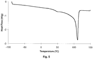
- Differential Scanning Calorimetry is performed with a DSC Q1000 (heat flux principle) using a RCS-cooling unit from TA INSTRUMENTS, USA.
- a sample is taken from the foil.
- the sample is put into an aluminium sampleholder (diameter 6.6 mm) from TA-Instruments and sealed by an aluminium lid.
- the sample is then heated in an inert atmosphere (50 ml/min nitrogen flow) at 20°C/min from -90°C to 150°C.
- the curing degree is tested on a coating immediately after curing with UV light.
- the cured coating is rubbed with the means of a Qtip.
- the coating is considered to be fully cured.
- the coating is only partly cured.
- the coating is not cured.
- the adhesion of the cured coating onto the substrate was tested with a tape.
- a black tape Tesa 4104/04 from TESA AG, Germany was taped onto the coating and the tape was removed immediately thereafter by hand.
- Table 1 shows the evaluation scale used for the adhesion quality. Table 1 % of coating removed by the tape Adhesion 0 to 10 % Excellent 10 to 20 % Acceptable > 20 % Not OK
- the surface tension of the curable liquids and inks were measured with a KRÜSS tensiometer K9 from KRÜSS GmbH, Germany at 25°C after 60 seconds.
- the surface energy of a substrate was measured using a set of test pens, containing fluids of a defined surface tension from 30 to 44 mN/m, available from ARCOTEST, Germany.
- a surface energy measurement result of 36 - 38 mJ/m 2 means that the red ink of a test pen with a surface tension of 36 mN/m results in spreading of the red ink, while the red ink of a test pen with a surface tension of 38 mN/m results did not result in spreading of the red ink.
- the gloss was measured at an angle of 60° with a REFO 60 available from Dr. LANGE GmbH, Germany.
- This example illustrates the improvement of adhesion of a radiation curable inkjet ink to a substrate typically used for making plastic bags in a temperature working area that normally would not be considered by a skilled person in inkjet printing.
- the storage modulus at -80°C is about 1900 MPa (stiffness about 59500 N/m).
- the mechanical strength of the LDPE foil decreases sharply to about 200 Mpa at room temperature (stiffness 6500 N/m) and to only about 14 MPa at 100°C.
- the loss modulus peaks at about -22°C, this corresponds with the glass transition temperature (Tg).
- Tg glass transition temperature
- a LDPE foil was immobilized using a vacuum suction system on the metal plate of a thermostatically controllable coating device from ELCOMETER, Belgium.
- the metal plate was heated using a circulation system employing a hot water bath.
- the surface temperature of the coating was measured with a hand held IR thermometer Optex Thermo-Hunter Model PT-3LF from OPTEX, USA.
- a non-aqueous cyan radiation curable inkjet ink :AGORIX Cyan having a surface tension of 22 mN/m was coated on the LDPE foil using a 10 ⁇ m wired bar.
- the heated coating was then cured under a Fe-doped mercury UV lamp 140 W/cm (DPL type 10041) from DPL industri A/S (Denmark).
- DPL type 10041 DPL industri A/S
- the shutter of the UV lamp was closed, so only a small amount of stray UV light hit the coating, then the shutter was opened and the coating was irradiated during 2 seconds, while the UV power was measured with a UV Power Puck from EIT Inc (USA).
- the stray light and the two second DPL exposure were measured to have together a dose of 5.82 J/cm 2 and a peak intensity of 2.65 W/cm 2 .
- the curing degree of the coating was evaluated immediately after curing with UV light.
- the hot water bath was set so that two surface temperatures of the LDPE foil were obtained: 24 and 50°C.
- the comparative sample COMP-1 was coated at 24°C and appeared fully cured.
- Comparative sample COMP-2 was prepared in the same way as comparative sample COMP-1 except that the sample was given a 4 seconds UV-exposure with the Fe-doped mercury UV lamp.
- Inventive sample INV-1 was coated at 50°C and cured in the same way as comparative sample COMP-1. The results of the adhesion test are shown in Table 2.
- Table 2 Sample Surface temperature Curing degree Adhesion COMP-1 24°C Fully cured Not OK COMP-2 24°C Fully cured Not OK INV-1 50°C Fully cured Excellent
- the surface energy of the LDPE foil was measured to be 36-38 mJ/m 2 . After giving a heat treatment of 50°C for 10 seconds, the surface energy of the LDPE foil was measured and found to be unchanged.
- This example illustrates a practical implementation of the invention on a single pass inkjet printer.
- a :Dotrix modular single pass inkjet printer from AGFA GRAPHICS was modified to accommodate for transport of a thin web (75 ⁇ m) of polyethylene foil. These modifications included different positioning of dancer rolls, use of spreader rolls, use of lower friction bearings,... All these modification are well-known for a skilled person in printing presses for flexographic printing on webs of thin flexible foils.
- the curing means of the :Dotrix modular single pass inkjet printer was adapted.
- a shutter having a dichroitic reflector was installed, whereby the peak intensity onto the substrate was increased.
- the standard curing lamp of the printer was replaced by a thinner mercury arc lamp of smaller electrical power, thus creating less heat and also allowing higher focussing, whereby again a higher power was obtained in function of the dose.
- the temperature in the curing zone just above the substrate was monitored during operation of the printer and could be maintained in the range of 70 to 80°C.
- temperatures of up to 110°C could be registered.
- Flexographic printing applications often use a thin layer of primer, preferably less than 10 ⁇ m, on the substrate to achieve certain desired properties, such as e.g. a glossy or a mat finish, better adhesion, a specific background color, etc.
- the primers of Table 3 were coated on the LDPE foil using a bar coater and a 4 ⁇ m wired bar. Each coated sample was pre-cured under air using a Fusion DRSE-120 conveyer, equipped with a Fusion VPS/I600 lamp (H-bulb), which transported the samples under the UV-lamp on a conveyer belt at a speed of 20 m/min. All the primed samples were mounted into a web of LDPE foil and the web containg the samples was mounted into the single pass printer. On part of each primed sample a colour image was printed using the non-aqueous cyan radiation curable inkjet inkset :AGORIX from AGFA GRAPHICS, Belgium. The same colour image was also printed on the unprimed LDPE.
- the primers and colour images were found to be fully cured. Subsequently the adhesion quality of the primers on the LDPE foil and the adhesion quality of the ink on the primed and unprimed LDPE foil were tested. The surface tension of the liquid primers and the gloss at 60° of the cured primers were measured. The results are shown in Table 4.
- a glossy finish or a mat finish can be obtained by using for example primers PR-8 and PR-9 respectively PR-11 and PR-12.
- the primers in Table 4 are sorted in function of their surface tension. It can be seen that very good adhesion of the primer on the LDPE foil was observed when the surface tension of the primer was at least 4 mN/m smaller than the surface energy of the LDPE foil. A good adhesion of the inkjet inks, having an average surface tension of 22 mN/m, onto the primed substrate was observed as long as the surface tension of the inks was equal or smaller than the surface tension of the primers.
Claims (9)
- Ein mit strahlungshärtbaren Tintenstrahltinten arbeitendes Tintenstrahldruckverfahren zur Herstellung bedruckter biegsamer Folien und Kunststoffbeutel, umfassend die folgenden Schritte:a) Bereitstellen eines bahnartigen polymeren Substrats mit einem maximalen Tan δ-Wert zwischen 40°C und 110°C,b) Bereitstellen eines Einzeldurchgangs-Tintenstrahldruckers, der mindestens einen seitenbreiten Druckkopf oder mindestens einen Satz versetzt angeordneter Druckköpfe, Mittel zum Befördern des bahnartigen Aufzeichnungselements und Härtungsmittel umfasst,c) Aufspritzen einer nicht-wässrigen strahlungshärtbaren Tintenstrahlflüssigkeit mit einer Oberflächenspannung SLiq auf das bahnartige polymere Substrat mit einer Oberflächenenergie Ssub, wobei SLiq um mindestens 4 mN/m kleiner ist als SSub, undd) Härten der strahlungshärtbaren Flüssigkeit auf dem Substrat bei einer Oberflächentemperatur, die gleich oder höher der Temperatur des maximalen Tan 5-Wertes ist und unterhalb des Schmelzpunktes des polymeren Aufzeichnungselements liegt,wobei der maximale Tan δ-Wert durch dynamisch-mechanische Analyse bei einer Temperaturrampe von 3°C/Min. durch erzwungene Schwingung mit einem Zyklus von 1 Sekunde und einer Amplitude von 100 µm bestimmt wird.
- Das mit strahlungshärtbaren Tintenstrahltinten arbeitende Tintenstrahldruckverfahren nach Anspruch 1, wobei die durch ein UV-Härtungsmittel erzeugte Wärme zum Einstellen einer Oberflächentemperatur von mindestens 50°C verwendet wird.
- Das mit strahlungshärtbaren Tintenstrahltinten arbeitende Tintenstrahldruckverfahren nach Anspruch 1 oder 2, wobei die Oberflächentemperatur im Bereich von 50 bis 100°C liegt.
- Das mit strahlungshärtbaren Tintenstrahltinten arbeitende Tintenstrahldruckverfahren nach einem der Ansprüche 1 bis 3, wobei die strahlungshärtbare Flüssigkeit eine pigmenthaltige strahlungshärtbare Tintenstrahltinte ist.
- Das mit strahlungshärtbaren Tintenstrahltinten arbeitende Tintenstrahldruckverfahren nach einem der Ansprüche 1 bis 3, wobei eine pigmenthaltige strahlungshärtbare Tintenstrahltinte auf die strahlungshärtbare Flüssigkeit gedruckt wird.
- Das mit strahlungshärtbaren Tintenstrahltinten arbeitende Tintenstrahldruckverfahren nach Anspruch 5, wobei die Oberflächenspannung der pigmenthaltigen strahlungshärtbaren Tintenstrahltinte um nicht mehr als 5 mN/m unter der Oberflächenspannung der strahlungshärtbaren Flüssigkeit liegt.
- Das mit strahlungshärtbaren Tintenstrahltinten arbeitende Tintenstrahldruckverfahren nach einem der Ansprüche 1 bis 6, umfassend eine Koronabehandlung des Substrats.
- Das mit strahlungshärtbaren Tintenstrahltinten arbeitende Tintenstrahldruckverfahren nach einem der Ansprüche 1 bis 7, wobei das bahnartige polymere Substrat eine mit einem Primer versehene Oberfläche aufweist, wobei die Stärke der Primerschicht bei weniger als 5 µm liegt.
- Das mit strahlungshärtbaren Tintenstrahltinten arbeitende Tintenstrahldruckverfahren nach einem der Ansprüche 1 bis 8, wobei das bahnartige polymere Substrat ein Polyethylensubstrat, bevorzugt ein Substrat aus niederdichtem Polyethylen, ist.
Priority Applications (5)
| Application Number | Priority Date | Filing Date | Title |
|---|---|---|---|
| EP07119374.2A EP2053104B1 (de) | 2007-10-26 | 2007-10-26 | Strahlungshärtbare Tintenstrahldruckverfahren |
| PCT/EP2008/064018 WO2009053311A2 (en) | 2007-10-26 | 2008-10-17 | Radiation curable inkjet printing methods |
| US12/739,154 US8371688B2 (en) | 2007-10-26 | 2008-10-17 | Single pass radiation curable inkjet printing methods for producing printed flexible foils and plastic bags |
| CN200880112380.0A CN101835854B (zh) | 2007-10-26 | 2008-10-17 | 辐射可固化喷墨打印方法 |
| US13/714,487 US8684515B2 (en) | 2007-10-26 | 2012-12-14 | Single pass radiation curable inkjet printing methods for producing printed flexible foils and plastic bags |
Applications Claiming Priority (1)
| Application Number | Priority Date | Filing Date | Title |
|---|---|---|---|
| EP07119374.2A EP2053104B1 (de) | 2007-10-26 | 2007-10-26 | Strahlungshärtbare Tintenstrahldruckverfahren |
Publications (2)
| Publication Number | Publication Date |
|---|---|
| EP2053104A1 EP2053104A1 (de) | 2009-04-29 |
| EP2053104B1 true EP2053104B1 (de) | 2017-02-22 |
Family
ID=39191054
Family Applications (1)
| Application Number | Title | Priority Date | Filing Date |
|---|---|---|---|
| EP07119374.2A Not-in-force EP2053104B1 (de) | 2007-10-26 | 2007-10-26 | Strahlungshärtbare Tintenstrahldruckverfahren |
Country Status (4)
| Country | Link |
|---|---|
| US (2) | US8371688B2 (de) |
| EP (1) | EP2053104B1 (de) |
| CN (1) | CN101835854B (de) |
| WO (1) | WO2009053311A2 (de) |
Families Citing this family (23)
| Publication number | Priority date | Publication date | Assignee | Title |
|---|---|---|---|---|
| GB0911015D0 (en) | 2009-06-25 | 2009-08-12 | Sericol Ltd | Printing method |
| WO2011061136A1 (en) | 2009-11-18 | 2011-05-26 | Oce-Technologies B.V. | Method for applying a curable hot-melt ink on a medium |
| PL2335940T3 (pl) | 2009-12-21 | 2012-12-31 | Agfa Nv | Sposób druku atramentowego za jednym przebiegiem |
| WO2011136812A1 (en) | 2010-04-30 | 2011-11-03 | Hewlett-Packard Development Company, L.P. | Printing system |
| FR2961743B1 (fr) * | 2010-06-28 | 2013-03-15 | Cellulaires Tech Soc D | Procede de fabrication d'un element en mousse pour la decoration, l'ameublement, le calage et/ou le transport d'objets, ou similaire, et element en mousse obtenu |
| US20120141180A1 (en) * | 2010-12-07 | 2012-06-07 | Xerox Corporation | Surface treatment for improving the adhesion of phase change ink on substrates |
| EP2633998B1 (de) | 2012-03-02 | 2020-10-21 | Agfa Nv | Verwendung einer Tintenstrahldruckvorrichtung mit Einzeldurchgang |
| EP2711191B1 (de) | 2012-09-21 | 2014-11-12 | Wipf AG | Verfahren zum Bedrucken von Folien |
| KR101557841B1 (ko) * | 2012-12-07 | 2015-10-06 | 제일모직주식회사 | 이방 전도성 필름 |
| EP3024591B1 (de) * | 2013-07-25 | 2024-01-24 | Shurtape Technologies, LLC | Digital gedrucktes isolierband |
| US10072190B2 (en) | 2013-07-25 | 2018-09-11 | Shurtape Technologies, Llc | Digital printed duct tape |
| US10603881B2 (en) | 2013-07-25 | 2020-03-31 | Shurtape Technologies, Llc | Digital printed duct tape |
| GB201316523D0 (en) * | 2013-09-17 | 2013-10-30 | Sericol Ltd | Printing Method |
| JP2015124356A (ja) * | 2013-12-27 | 2015-07-06 | 理想科学工業株式会社 | 非水系顔料インク |
| GB2534113B (en) * | 2014-09-12 | 2020-11-18 | Domino Uk Ltd | Ink composition |
| US10180248B2 (en) | 2015-09-02 | 2019-01-15 | ProPhotonix Limited | LED lamp with sensing capabilities |
| CN107459871B (zh) * | 2016-07-11 | 2018-05-25 | 珠海赛纳打印科技股份有限公司 | 3d喷墨打印用光固化透明墨水及其制备方法 |
| EP3493994B1 (de) | 2016-10-12 | 2022-02-16 | Hewlett-Packard Development Company, L.P. | Ausgabe entkontentierter fluide |
| US20190070822A1 (en) * | 2017-09-03 | 2019-03-07 | Steve Kohn | Products Made from Paper, Polyethylene or other Materials with Digitally Printed Images |
| US20190240897A1 (en) | 2018-02-07 | 2019-08-08 | Xerox Corporation | Transfer of uv print onto curved surfaces with stretchable uv inks |
| JP7228123B2 (ja) * | 2018-09-25 | 2023-02-24 | セイコーエプソン株式会社 | インクジェットインク組成物、インクパック、及びインクジェット記録方法 |
| AR120745A1 (es) * | 2019-12-18 | 2022-03-16 | Sicpa Holding Sa | Tintas de impresión offset curables con radicales por uv-led y procesos de impresión |
| US11446946B2 (en) | 2020-09-14 | 2022-09-20 | Assa Abloy Ab | Method for ink jet durability and adhesion |
Family Cites Families (17)
| Publication number | Priority date | Publication date | Assignee | Title |
|---|---|---|---|---|
| US4529087A (en) * | 1983-10-21 | 1985-07-16 | Maine Poly, Inc. | Printed antistatic plastic bag |
| GB9725928D0 (en) * | 1997-12-05 | 1998-02-04 | Xaar Plc | Radiation curable ink jet ink compositions |
| US6447112B1 (en) * | 2000-05-01 | 2002-09-10 | 3M Innovative Properties Company | Radiation curing system and method for inkjet printers |
| US20020067394A1 (en) * | 2000-10-10 | 2002-06-06 | Toyo Ink Mfg. Co., Ltd. | Ink jet printing to synthetic resin substrate |
| US6550906B2 (en) * | 2001-01-02 | 2003-04-22 | 3M Innovative Properties Company | Method and apparatus for inkjet printing using UV radiation curable ink |
| US6550905B1 (en) | 2001-11-19 | 2003-04-22 | Dotrix N.V. | Radiation curable inkjet ink relatively free of photoinitiator and method and apparatus of curing the ink |
| JP4561031B2 (ja) * | 2002-11-27 | 2010-10-13 | コニカミノルタホールディングス株式会社 | 活性光線硬化型インクジェット無溶剤インク及び画像形成方法 |
| US7682970B2 (en) * | 2003-07-16 | 2010-03-23 | The Regents Of The University Of California | Maskless nanofabrication of electronic components |
| US20050205200A1 (en) * | 2004-03-22 | 2005-09-22 | Carmen Flosbach | Process for the production of backing foils provided on one side with a transparent coating and an image |
| US8083338B2 (en) * | 2004-05-06 | 2011-12-27 | Agfa Graphics N.V. | Radiation-curable ink-jet printing |
| DE602005007675D1 (de) * | 2004-10-29 | 2008-08-07 | Agfa Graphics Nv | Druck der strahlungshärtbaren Tinten in eine flüssige strahlungshärtbare Schicht |
| US7520601B2 (en) * | 2004-10-29 | 2009-04-21 | Agfa Graphics, N.V. | Printing of radiation curable inks into a radiation curable liquid layer |
| EP1911817B1 (de) * | 2005-07-25 | 2014-05-21 | Toyo Ink Mfg. Co., Ltd. | Durch aktive Energie-Stahlung härtbare Tinte zum Tintenstrahl-Drucken |
| JP2007211081A (ja) * | 2006-02-08 | 2007-08-23 | Konica Minolta Holdings Inc | インクジェットインク及びインクジェット記録方法 |
| JP5300175B2 (ja) * | 2006-03-02 | 2013-09-25 | 富士フイルム株式会社 | インクジェット記録用インクセットおよびインクジェット記録方法 |
| PL1935659T3 (pl) * | 2006-12-21 | 2010-04-30 | Agfa Nv | Sposoby drukowania strumieniowego i zestaw tuszów do drukarek strumieniowych |
| US20080286542A1 (en) * | 2007-05-17 | 2008-11-20 | Richard Allen Hayes | Decorative safety glass |
-
2007
- 2007-10-26 EP EP07119374.2A patent/EP2053104B1/de not_active Not-in-force
-
2008
- 2008-10-17 CN CN200880112380.0A patent/CN101835854B/zh not_active Expired - Fee Related
- 2008-10-17 WO PCT/EP2008/064018 patent/WO2009053311A2/en active Application Filing
- 2008-10-17 US US12/739,154 patent/US8371688B2/en not_active Expired - Fee Related
-
2012
- 2012-12-14 US US13/714,487 patent/US8684515B2/en not_active Expired - Fee Related
Non-Patent Citations (1)
| Title |
|---|
| None * |
Also Published As
| Publication number | Publication date |
|---|---|
| US8371688B2 (en) | 2013-02-12 |
| EP2053104A1 (de) | 2009-04-29 |
| WO2009053311A3 (en) | 2009-06-18 |
| CN101835854A (zh) | 2010-09-15 |
| CN101835854B (zh) | 2014-12-17 |
| US20100309268A1 (en) | 2010-12-09 |
| US20130100221A1 (en) | 2013-04-25 |
| WO2009053311A2 (en) | 2009-04-30 |
| US8684515B2 (en) | 2014-04-01 |
Similar Documents
| Publication | Publication Date | Title |
|---|---|---|
| EP2053104B1 (de) | Strahlungshärtbare Tintenstrahldruckverfahren | |
| EP2305762B1 (de) | UV-härtbare Tintenstrahlzusammensetzungen für sehr dichte Druckköpfe | |
| AU2013270718B2 (en) | Radiation curable inkjet inks and industrial inkjet printing methods | |
| AU2014320278B2 (en) | Radiation curable compositions for food packaging | |
| EP2053102B1 (de) | Strahlenhärtbare Tintenstrahldruckfarben und Tinten mit verbesserter Vergilbungsbeständigkeit | |
| US8372913B2 (en) | Radiation curable inkjet printing methods | |
| JP5697686B2 (ja) | 1回通過インクジェット印刷法 | |
| AU2015257897B2 (en) | Inkjet printing outdoor graphics | |
| WO2021099145A1 (en) | Radiation curable inkjet ink sets | |
| WO2015169661A1 (en) | Inkjet printing outdoor graphics |
Legal Events
| Date | Code | Title | Description |
|---|---|---|---|
| PUAI | Public reference made under article 153(3) epc to a published international application that has entered the european phase |
Free format text: ORIGINAL CODE: 0009012 |
|
| AK | Designated contracting states |
Kind code of ref document: A1 Designated state(s): AT BE BG CH CY CZ DE DK EE ES FI FR GB GR HU IE IS IT LI LT LU LV MC MT NL PL PT RO SE SI SK TR |
|
| AX | Request for extension of the european patent |
Extension state: AL BA HR MK RS |
|
| 17P | Request for examination filed |
Effective date: 20091029 |
|
| AKX | Designation fees paid |
Designated state(s): AT BE BG CH CY CZ DE DK EE ES FI FR GB GR HU IE IS IT LI LT LU LV MC MT NL PL PT RO SE SI SK TR |
|
| 17Q | First examination report despatched |
Effective date: 20091221 |
|
| GRAP | Despatch of communication of intention to grant a patent |
Free format text: ORIGINAL CODE: EPIDOSNIGR1 |
|
| INTG | Intention to grant announced |
Effective date: 20160914 |
|
| RIN1 | Information on inventor provided before grant (corrected) |
Inventor name: BRACKE, PETER Inventor name: VAN THILLO, ETIENNE Inventor name: VAN DYCK, GEERT |
|
| GRAS | Grant fee paid |
Free format text: ORIGINAL CODE: EPIDOSNIGR3 |
|
| GRAA | (expected) grant |
Free format text: ORIGINAL CODE: 0009210 |
|
| AK | Designated contracting states |
Kind code of ref document: B1 Designated state(s): AT BE BG CH CY CZ DE DK EE ES FI FR GB GR HU IE IS IT LI LT LU LV MC MT NL PL PT RO SE SI SK TR |
|
| REG | Reference to a national code |
Ref country code: GB Ref legal event code: FG4D |
|
| REG | Reference to a national code |
Ref country code: CH Ref legal event code: EP |
|
| REG | Reference to a national code |
Ref country code: AT Ref legal event code: REF Ref document number: 869262 Country of ref document: AT Kind code of ref document: T Effective date: 20170315 |
|
| REG | Reference to a national code |
Ref country code: IE Ref legal event code: FG4D |
|
| REG | Reference to a national code |
Ref country code: DE Ref legal event code: R096 Ref document number: 602007049848 Country of ref document: DE |
|
| REG | Reference to a national code |
Ref country code: LT Ref legal event code: MG4D |
|
| REG | Reference to a national code |
Ref country code: NL Ref legal event code: MP Effective date: 20170222 |
|
| REG | Reference to a national code |
Ref country code: AT Ref legal event code: MK05 Ref document number: 869262 Country of ref document: AT Kind code of ref document: T Effective date: 20170222 |
|
| PG25 | Lapsed in a contracting state [announced via postgrant information from national office to epo] |
Ref country code: FI Free format text: LAPSE BECAUSE OF FAILURE TO SUBMIT A TRANSLATION OF THE DESCRIPTION OR TO PAY THE FEE WITHIN THE PRESCRIBED TIME-LIMIT Effective date: 20170222 Ref country code: GR Free format text: LAPSE BECAUSE OF FAILURE TO SUBMIT A TRANSLATION OF THE DESCRIPTION OR TO PAY THE FEE WITHIN THE PRESCRIBED TIME-LIMIT Effective date: 20170523 Ref country code: LT Free format text: LAPSE BECAUSE OF FAILURE TO SUBMIT A TRANSLATION OF THE DESCRIPTION OR TO PAY THE FEE WITHIN THE PRESCRIBED TIME-LIMIT Effective date: 20170222 |
|
| PG25 | Lapsed in a contracting state [announced via postgrant information from national office to epo] |
Ref country code: AT Free format text: LAPSE BECAUSE OF FAILURE TO SUBMIT A TRANSLATION OF THE DESCRIPTION OR TO PAY THE FEE WITHIN THE PRESCRIBED TIME-LIMIT Effective date: 20170222 Ref country code: NL Free format text: LAPSE BECAUSE OF FAILURE TO SUBMIT A TRANSLATION OF THE DESCRIPTION OR TO PAY THE FEE WITHIN THE PRESCRIBED TIME-LIMIT Effective date: 20170222 Ref country code: ES Free format text: LAPSE BECAUSE OF FAILURE TO SUBMIT A TRANSLATION OF THE DESCRIPTION OR TO PAY THE FEE WITHIN THE PRESCRIBED TIME-LIMIT Effective date: 20170222 Ref country code: BG Free format text: LAPSE BECAUSE OF FAILURE TO SUBMIT A TRANSLATION OF THE DESCRIPTION OR TO PAY THE FEE WITHIN THE PRESCRIBED TIME-LIMIT Effective date: 20170522 Ref country code: SE Free format text: LAPSE BECAUSE OF FAILURE TO SUBMIT A TRANSLATION OF THE DESCRIPTION OR TO PAY THE FEE WITHIN THE PRESCRIBED TIME-LIMIT Effective date: 20170222 Ref country code: PT Free format text: LAPSE BECAUSE OF FAILURE TO SUBMIT A TRANSLATION OF THE DESCRIPTION OR TO PAY THE FEE WITHIN THE PRESCRIBED TIME-LIMIT Effective date: 20170622 Ref country code: LV Free format text: LAPSE BECAUSE OF FAILURE TO SUBMIT A TRANSLATION OF THE DESCRIPTION OR TO PAY THE FEE WITHIN THE PRESCRIBED TIME-LIMIT Effective date: 20170222 |
|
| REG | Reference to a national code |
Ref country code: FR Ref legal event code: PLFP Year of fee payment: 11 |
|
| PG25 | Lapsed in a contracting state [announced via postgrant information from national office to epo] |
Ref country code: EE Free format text: LAPSE BECAUSE OF FAILURE TO SUBMIT A TRANSLATION OF THE DESCRIPTION OR TO PAY THE FEE WITHIN THE PRESCRIBED TIME-LIMIT Effective date: 20170222 Ref country code: IT Free format text: LAPSE BECAUSE OF FAILURE TO SUBMIT A TRANSLATION OF THE DESCRIPTION OR TO PAY THE FEE WITHIN THE PRESCRIBED TIME-LIMIT Effective date: 20170222 Ref country code: SK Free format text: LAPSE BECAUSE OF FAILURE TO SUBMIT A TRANSLATION OF THE DESCRIPTION OR TO PAY THE FEE WITHIN THE PRESCRIBED TIME-LIMIT Effective date: 20170222 Ref country code: RO Free format text: LAPSE BECAUSE OF FAILURE TO SUBMIT A TRANSLATION OF THE DESCRIPTION OR TO PAY THE FEE WITHIN THE PRESCRIBED TIME-LIMIT Effective date: 20170222 Ref country code: CZ Free format text: LAPSE BECAUSE OF FAILURE TO SUBMIT A TRANSLATION OF THE DESCRIPTION OR TO PAY THE FEE WITHIN THE PRESCRIBED TIME-LIMIT Effective date: 20170222 |
|
| REG | Reference to a national code |
Ref country code: DE Ref legal event code: R097 Ref document number: 602007049848 Country of ref document: DE |
|
| PG25 | Lapsed in a contracting state [announced via postgrant information from national office to epo] |
Ref country code: PL Free format text: LAPSE BECAUSE OF FAILURE TO SUBMIT A TRANSLATION OF THE DESCRIPTION OR TO PAY THE FEE WITHIN THE PRESCRIBED TIME-LIMIT Effective date: 20170222 Ref country code: DK Free format text: LAPSE BECAUSE OF FAILURE TO SUBMIT A TRANSLATION OF THE DESCRIPTION OR TO PAY THE FEE WITHIN THE PRESCRIBED TIME-LIMIT Effective date: 20170222 |
|
| RAP2 | Party data changed (patent owner data changed or rights of a patent transferred) |
Owner name: AGFA NV |
|
| PLBE | No opposition filed within time limit |
Free format text: ORIGINAL CODE: 0009261 |
|
| STAA | Information on the status of an ep patent application or granted ep patent |
Free format text: STATUS: NO OPPOSITION FILED WITHIN TIME LIMIT |
|
| REG | Reference to a national code |
Ref country code: DE Ref legal event code: R081 Ref document number: 602007049848 Country of ref document: DE Owner name: AGFA NV, BE Free format text: FORMER OWNER: AGFA GRAPHICS N.V., MORTSEL, BE |
|
| 26N | No opposition filed |
Effective date: 20171123 |
|
| PG25 | Lapsed in a contracting state [announced via postgrant information from national office to epo] |
Ref country code: SI Free format text: LAPSE BECAUSE OF FAILURE TO SUBMIT A TRANSLATION OF THE DESCRIPTION OR TO PAY THE FEE WITHIN THE PRESCRIBED TIME-LIMIT Effective date: 20170222 |
|
| REG | Reference to a national code |
Ref country code: BE Ref legal event code: HC Owner name: AGFA NV; BE Free format text: DETAILS ASSIGNMENT: CHANGE OF OWNER(S), CHANGEMENT DE NOM DU PROPRIETAIRE; FORMER OWNER NAME: AGFA GRAPHICS N.V. Effective date: 20171211 |
|
| PG25 | Lapsed in a contracting state [announced via postgrant information from national office to epo] |
Ref country code: MC Free format text: LAPSE BECAUSE OF FAILURE TO SUBMIT A TRANSLATION OF THE DESCRIPTION OR TO PAY THE FEE WITHIN THE PRESCRIBED TIME-LIMIT Effective date: 20170222 |
|
| REG | Reference to a national code |
Ref country code: CH Ref legal event code: PL |
|
| REG | Reference to a national code |
Ref country code: IE Ref legal event code: MM4A |
|
| PG25 | Lapsed in a contracting state [announced via postgrant information from national office to epo] |
Ref country code: LU Free format text: LAPSE BECAUSE OF NON-PAYMENT OF DUE FEES Effective date: 20171026 Ref country code: LI Free format text: LAPSE BECAUSE OF NON-PAYMENT OF DUE FEES Effective date: 20171031 Ref country code: CH Free format text: LAPSE BECAUSE OF NON-PAYMENT OF DUE FEES Effective date: 20171031 |
|
| REG | Reference to a national code |
Ref country code: FR Ref legal event code: CD Owner name: AGFA NV, BE Effective date: 20180628 |
|
| REG | Reference to a national code |
Ref country code: FR Ref legal event code: PLFP Year of fee payment: 12 |
|
| PG25 | Lapsed in a contracting state [announced via postgrant information from national office to epo] |
Ref country code: MT Free format text: LAPSE BECAUSE OF NON-PAYMENT OF DUE FEES Effective date: 20171026 |
|
| PG25 | Lapsed in a contracting state [announced via postgrant information from national office to epo] |
Ref country code: IE Free format text: LAPSE BECAUSE OF NON-PAYMENT OF DUE FEES Effective date: 20171026 |
|
| PGFP | Annual fee paid to national office [announced via postgrant information from national office to epo] |
Ref country code: FR Payment date: 20180911 Year of fee payment: 12 |
|
| PGFP | Annual fee paid to national office [announced via postgrant information from national office to epo] |
Ref country code: GB Payment date: 20180911 Year of fee payment: 12 Ref country code: BE Payment date: 20180911 Year of fee payment: 12 |
|
| PGFP | Annual fee paid to national office [announced via postgrant information from national office to epo] |
Ref country code: DE Payment date: 20180911 Year of fee payment: 12 |
|
| PG25 | Lapsed in a contracting state [announced via postgrant information from national office to epo] |
Ref country code: HU Free format text: LAPSE BECAUSE OF FAILURE TO SUBMIT A TRANSLATION OF THE DESCRIPTION OR TO PAY THE FEE WITHIN THE PRESCRIBED TIME-LIMIT; INVALID AB INITIO Effective date: 20071026 |
|
| PG25 | Lapsed in a contracting state [announced via postgrant information from national office to epo] |
Ref country code: CY Free format text: LAPSE BECAUSE OF NON-PAYMENT OF DUE FEES Effective date: 20170222 |
|
| PG25 | Lapsed in a contracting state [announced via postgrant information from national office to epo] |
Ref country code: TR Free format text: LAPSE BECAUSE OF FAILURE TO SUBMIT A TRANSLATION OF THE DESCRIPTION OR TO PAY THE FEE WITHIN THE PRESCRIBED TIME-LIMIT Effective date: 20170222 |
|
| REG | Reference to a national code |
Ref country code: DE Ref legal event code: R119 Ref document number: 602007049848 Country of ref document: DE |
|
| PG25 | Lapsed in a contracting state [announced via postgrant information from national office to epo] |
Ref country code: DE Free format text: LAPSE BECAUSE OF NON-PAYMENT OF DUE FEES Effective date: 20200501 Ref country code: IS Free format text: LAPSE BECAUSE OF FAILURE TO SUBMIT A TRANSLATION OF THE DESCRIPTION OR TO PAY THE FEE WITHIN THE PRESCRIBED TIME-LIMIT Effective date: 20170622 |
|
| REG | Reference to a national code |
Ref country code: BE Ref legal event code: MM Effective date: 20191031 |
|
| PG25 | Lapsed in a contracting state [announced via postgrant information from national office to epo] |
Ref country code: BE Free format text: LAPSE BECAUSE OF NON-PAYMENT OF DUE FEES Effective date: 20191031 |
|
| GBPC | Gb: european patent ceased through non-payment of renewal fee |
Effective date: 20191026 |
|
| PG25 | Lapsed in a contracting state [announced via postgrant information from national office to epo] |
Ref country code: GB Free format text: LAPSE BECAUSE OF NON-PAYMENT OF DUE FEES Effective date: 20191026 Ref country code: FR Free format text: LAPSE BECAUSE OF NON-PAYMENT OF DUE FEES Effective date: 20191031 |