EP2052960A2 - Bicycle control system - Google Patents
Bicycle control system Download PDFInfo
- Publication number
- EP2052960A2 EP2052960A2 EP08005622A EP08005622A EP2052960A2 EP 2052960 A2 EP2052960 A2 EP 2052960A2 EP 08005622 A EP08005622 A EP 08005622A EP 08005622 A EP08005622 A EP 08005622A EP 2052960 A2 EP2052960 A2 EP 2052960A2
- Authority
- EP
- European Patent Office
- Prior art keywords
- switch
- additional
- switch device
- signal
- code
- Prior art date
- Legal status (The legal status is an assumption and is not a legal conclusion. Google has not performed a legal analysis and makes no representation as to the accuracy of the status listed.)
- Granted
Links
Images



Classifications
-
- B—PERFORMING OPERATIONS; TRANSPORTING
- B62—LAND VEHICLES FOR TRAVELLING OTHERWISE THAN ON RAILS
- B62M—RIDER PROPULSION OF WHEELED VEHICLES OR SLEDGES; POWERED PROPULSION OF SLEDGES OR SINGLE-TRACK CYCLES; TRANSMISSIONS SPECIALLY ADAPTED FOR SUCH VEHICLES
- B62M25/00—Actuators for gearing speed-change mechanisms specially adapted for cycles
- B62M25/08—Actuators for gearing speed-change mechanisms specially adapted for cycles with electrical or fluid transmitting systems
Definitions
- This invention generally relates to a bicycle control system that conducts interval communications from a rider operable switch device to a cycle computer. More specifically, the invention relates to a bicycle control system in which a switch operation signal is correctly recognized by a cycle computer even if a communication outage (e.g., interference or interruption in communications) occurs.
- a communication outage e.g., interference or interruption in communications
- Bicycling is becoming an increasingly more popular form of recreation as well as a means of transportation. Moreover, bicycling has become a very popular competitive sport for both amateurs and professionals. Whether the bicycle is used for recreation, transportation or competition, the bicycle industry is constantly improving the various components of the bicycle.
- bicycles have been equipped with electrical components to make riding easier and more enjoyable for the rider.
- Some bicycles are equipped with automatic shifting units that are automatically adjusted according to the riding conditions that are determined by a cycle computer or control unit.
- the front and rear derailleurs have recently been automated.
- various electronic devices have been used to determine one or more operating parameters for controlling the derailleurs and providing information to the rider.
- the cycle computer or control unit of the bicycle not only provides information to the rider, but is also used in controlling various components of the bicycle.
- the bicycle In a conventional bicycle control system, the bicycle is provided with a plurality of sensors (speed sensor, cadence sensor, etc.) and a cycle computer.
- the sensors speed sensor, cadence sensor, etc.
- the cycle computer is typically mounted on the bicycle handlebar.
- the bicycle cycle computer displays various kinds of information regarding the speed, the pedal revolution per minute (rpm), the gear in operation, the pulse of the rider, the ambient temperature, the geographical height and the like.
- control switches are provided for inputting commands or control signals to the cycle computer.
- the control switches are attached at grip parts (both ends) of the bicycle handlebar.
- wires are used to connect each of the sensors and the control switches to the cycle computer.
- some bicycle control system use wireless communications to communicate signals to the cycle computer.
- the cycle computer and the input devices communicate by wireless communications (radio communication, or infrared communication). For example, if an upshift control switch is pressed, the shift control switch sends a switch signal to the cycle computer.
- the cycle computer determines what this signal is, what does this signal means, and what the value of the signal is.
- the cycle computer detects and interprets "this signal is an upshift signal", and sends a command signal that directs a (front or rear) derailleur to upshift.
- the cycle computer needs time for detecting and interpreting the signal from the switch unit. Thus, the data can not be transmitted and received in real time. Therefore, if a communication outage happens due some interference or interruption in communications, then the data may be unrecognizable or falsely recognized.
- One object of the present invention is to provide a bicycle control system in which a switch operation signal is correctly recognized by a cycle computer even if a communication outage (e.g., interference or interruption in communications) occurs.
- a communication outage e.g., interference or interruption in communications
- the foregoing object can basically be attained by providing a bicycle control system that comprises a switch device and a cycle computer.
- the switch device includes a switch operation member, a sensor arranged relative to the switch operation member to detect operation of the switch operation member, a processing unit operatively coupled to the sensor and a transmitter arranged to transmit an output signal.
- the cycle computer includes a receiver arranged to receive the output signal from the transmitter of the switch device.
- the processing unit of the switch device includes an identification code generating member, an operating signal generating member and an output member.
- the identification code generating member generates identification code related to identification of the switch device.
- the operating signal generating member generates an operation code indicative of operation of the switch operation member.
- the output member combines the identification code and the operation code as the output signal to be transmitted by the transmitter of the switch device.
- Figure 1 is a side elevational view of a bicycle equipped with a bicycle control system that includes a cycle computer, a pair of sensors and a pair of sensed elements (magnets) in accordance with one preferred embodiment;
- FIG. 2 is a top perspective view of the handlebar portion of the bicycle showing the cycle computer in accordance with the illustrated embodiment
- FIG. 3 is a simplified schematic view of the communication between way wireless communications between the cycle computer and the switch units in accordance with the illustrated embodiment
- Figure 4 is a simplified side elevational view of one of the switch units with the housing broken away to reveal the internal structure of the switch unit;
- FIG. 5 is a simplified block diagram of the microprocessor of one of the switch units
- Figure 6 is a timing chart showing the periodic transmission intervals of the two switch units with the transmission intervals of the switch units being offset;
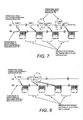
- Figure 7 is a timing chart indicating the correlation between an operation signal received by the microprocessor, and the reception of the output signal by the cycle computer in which only one of the switch units is being operated;
- Figure 8 is another timing chart, similar to Figure 7 , indicating the correlation between an operation signal received by the microprocessor, and the reception of the output signal by the cycle computer in which only one of the switch units is being operated;
- Figure 9 is a timing chart indicating the correlation between a pair of operation signals received by the microprocessor, and the reception of the output signal by the cycle computer in which both of the switch units are being operated.
- a bicycle 10 is illustrated that is equipped with a bicycle control system 12 that controls the shifting of the bicycle 10 and the stiffness of the suspension of the of the bicycle 10.
- the bicycle control system 12 includes a cycle computer 14, a first electrical switch unit 16, a second electrical switch unit 18, a front electrically powered derailleur 20, a rear electrically powered derailleur 22, a front suspension fork 24 and a rear shock absorber 26.
- the bicycle control system 12 preferably conducts interval wireless communications between the cycle computer 14 and the switch units 16 and 18.
- the cycle computer 14 communications shift signals to the derailleurs 20 and 22 via wires or wirelessly communications for controlling the shifting of the derailleurs 20 and 22.
- the cycle computer 14 communications suspension control signals to the front suspension fork 24 and the rear shock absorber 26 via wires or wirelessly communications for controlling the stiffness of the front suspension fork 24 and the rear shock absorber 26.
- the switch units 16 and 18 are used to control shifting and suspension stiffness, it will be apparent to those skilled in the art from this disclosure that the switch units 16 and 18 can be used to control other functions of the bicycle 10.
- the present invention can be implemented in any bicycle that utilizes a switch and a cycle computer that communicate with each other via wires or wirelessly communications.
- the present invention can also be implemented in either wired systems or wireless systems, which are subject to communication interference, a dropped communication signals or inaccurate signals being received by a cycle computer.
- the bicycle 10 includes, among other components, a main frame 30, a rear suspension arm 34, a handlebar unit 36, a drive train 38, a front wheel 40 and a rear wheel 42.
- the front suspension fork 24 is pivotally mounted to the main frame 30.
- the rear suspension arm 34 is pivotally mounted to the main frame 30.
- the shock absorber 26 is operatively mounted between the main frame 30 and the rear suspension arm 34 in a conventional manner.
- the handlebar unit 36 is fastened to an upper end of the front suspension fork 24.
- the front wheel 40 is mounted to the front fork 32, while the rear wheel 42 mounted to the rear suspension arm 34.
- the drive train 38 is mounted between the main frame 30 and the rear wheel 42 in a conventional manner.
- the cycle computer 14 and the switch units 16 and 18 are mounted to the handlebar unit 36. Wireless communications are conducted at prescribed intervals from the switch units 16 and 18 to the cycle computer 14 as seen in Figure 3 .
- the cycle computer 14 also wirelessly preferably transmits a confirmation signal to the electrical switch units 16 and 18 upon receiving updated signals from the switch units 16 and 18.
- the derailleurs 20 and 22 are operated by electrical switch units 16 and 18 (see Figure 2 ), respectively, via the cycle computer 14.
- the electrical switch units 16 and 18 are also used to control the stiffness's of the front suspension fork 24 and the shock absorber 26, respectively, via the cycle computer 14.
- a battery and/or one of the front wheels 40 and 42 is provided with a hub dynamo that serve as a power source for the electrical components.
- a battery 54 is mounted to the downwardly facing surface of a down tube 30a the main frame 30 and electrically coupled to the electrically powered derailleurs 20 and 22.
- the cycle computer 14 preferably has a built in battery.
- each of the electrical switch units 16 and 18 has its own built in battery.
- the cycle computer 14 basically includes an LCD display 60, a pair of input buttons 62, a microcomputer 64 and a two way wireless communication device 66.
- the microcomputer 64 is a conventional device with various control programs such as shifting control programs, suspension control programs and display programs.
- the microcomputer 64 includes, among other things a central processing unit CPU, an I/O interface and memory (RAM and ROM).
- the internal RAM of the microcomputer 64 stores statuses of operational flags and various control data.
- the two way wireless communication device 66 is a conventional device that includes a transmitter/receiver, which is indicated as T/R in Figure 5 .
- the two way wireless communication device 66 wirelessly communications with at least the shift units 16 and 18.
- the communication protocol (communication timings, communication data format and communication data contents) can be any conventional communication protocol or can be a specialized communication protocol as needed and/or desired.
- the microcomputer 64 of the cycle computer 14 controls the shifting of the derailleurs 20 and 22 and controls the stiffness's of the front suspension fork 24 and the shock absorber 26 in response to operation of the electrical switch units 16 and 18.
- the switch unit 16 has a pair of front gearshift switches 16a and 16b, which perform a manual gear-shifting operation of the front electrically powered derailleur 20 and a suspension mode switch 16c, which changes the stiffness of the front suspension fork 24 between hard and soft.
- the gearshift switch 16a is a switch for shifting the front electrically powered derailleur 20 incrementally downward.
- the gearshift switch 16b is used for incrementally shifting the front electrically powered derailleur 20 upward.
- the electrical switch unit 18 has a pair of rear gearshift switches 18a and 18b, which perform a manual gear-shifting operation of the rear electrically powered derailleur 22 and a shift mode switch 18c, which changes the stiffness of the shock absorber 26 between hard and soft.
- the gearshift switch 18a is a switch for shifting the rear electrically powered derailleur 22 incrementally downward.
- the gearshift switch 18b is used for incrementally shifting the rear electrically powered derailleur 22 upward.
- each of the switch units 16 and 18 includes a housing 70, a common toggle or rocker member 72 pivotally mounted to the housing 70, a push button 74, and a printed circuit board 76.
- the rocker member 72 is biased to a neutral rest position by a first biasing member 78 in the form of a torsion spring, while the push button 74 is biased to a neutral rest position by a second biasing member (not shown) in the form of a coiled compression spring.
- the printed circuit board 76 for the switch unit 16 includes a microprocessor (CPU) 80 in Figures 3 and 4 , and a transmitter/receiver (T/R) 82, while the printed circuit board 76 for the switch unit 18 includes a microprocessor (CPU) 90 in Figures 3 and 4 , and a transmitter/receiver (T/R) 92 in Figures 3 and 4 .
- CPU microprocessor
- T/R transmitter/receiver
- the printed circuit board 76 also includes first and second stationary contacts CS1 and CS2 that selectively engage first and second movable contacts CM1 and CM2 formed on the rocker member 72 in response to pivotal movement of the rocker member 72, and a third stationary contact CS3 that selectively engages a third movable contact CM3 formed on the push button 74 in response to linear movement of the push button 74 relative to the rocker member 72.
- the switch units 16 and 18 include both a rocker switch and a push button switch.
- the front and rear gearshift switches 16a and 18a are each formed by a part of the rocker member 72 and the contacts CM1 and CS1 in their respective switch units 16 and 18.
- the front and rear gearshift switches 16b and 18b are each formed by a part of the rocker member 72 and the contacts CM2 and CS2 in their respective switch units 16 and 18.
- the shift mode switches 16c and 18c are each formed by the push button 74 and the contacts CM3 and CS3 in their respective switch units 16 and 18.
- the printed circuit board 76 has three circuits that are opened and closed in response to the operation of the switches 16a to 16c (e.g., a switch sensor), respectively.
- the opening and closing of these three circuits by the selective operation of the switches 16a to 16c result an operation signal (pulse) to be transmitted to a corresponding one of the processing units A, B or C of the microprocessor 80 or 90 of the switch unit 16 or 18, respectively.
- the microprocessor 80 or 90 of the switch unit 16 or 18 determines which of the switches 16a to 16c or 18a to 18c was operated based on which electrical circuit of the printed circuit board 76 is closed in response to depressing the corresponding one of the switches 16a to 16c or 18a to 18c.
- the microprocessor 80 or 90 of the switch unit 16 or 18 also determines based on the length of the operation signal (pulse) that the operation signal (pulse) is either a short push signal or a long push signal.
- a short push signal is determined to occur when the electrical circuit is closed and opened within a single time period that acts as a prescribed time threshold.
- a counter or timer can be used to measure a period of time occurring between the start of the depressing of the switch and the releasing of the switch transmissions by the transmitter/receiver 92 of the switch unit 16 act as a prescribed time threshold in the illustrated embodiment.
- the rocker member 72 is biased to a neutral rest position by a first biasing member S in which the first and second movable contacts CM1 and CM2 are spaced from the first and second stationary contacts CS1 and CS2. Pivotal movement of the rocker member 72 in a first rotational direction about pivot P causes the first movable contact CM1 and the first stationary contact CS1 to contact each other. Pivotal movement of the rocker member 72 in a second rotational direction (opposite to the first rotational direction) about pivot P causes the second movable contact CM2 and the second stationary contact CS2 to contact each other.
- the microprocessor 80 or 90 When the rider has depressed the rocker member 72 for a short period of time below a first prescribed time threshold, then the microprocessor 80 or 90 generates a first operation signal as the operating signal to indicate a short switch operating action by the rider. On the other hand, when rider has depressed the rocker member 72 for a long period of time above a second prescribed time threshold, then the microprocessor 80 or 90 generates a second operation signal as the operating signal to indicate a long switch operating action by the rider.
- the second prescribed time threshold can be equal to or greater than the first prescribed time threshold as needed and/or desired.
- the shift mode switches 16c and 18c operate in the same manner as front and rear gearshift switches 16b and 18b in response to the push button 74 being depressed.
- the push button 74 is biased to a neutral rest position by a second biasing member (not shown).
- a second biasing member not shown.
- the microprocessor 80 or 90 detects the operation signal.
- the microprocessor 80 or 90 detects whether the rider has depressed the push button 74 for a short period of time or a long period of time.
- the microprocessor 80 or 90 When the rider has depressed the push button 74 for a short period of time below a first prescribed time threshold, then the microprocessor 80 or 90 generates a first operation signal as the operating signal to indicate a short switch operating action by the rider. On the other hand, when rider has depressed the push button 74 for a long period of time above a second prescribed time threshold, then the microprocessor 80 or 90 generates a second operation signal as the operating signal to indicate a long switch operating action by the rider.
- the second prescribed time threshold can be equal to or greater than the first prescribed time threshold as needed and/or desired.
- Each of the switch units 16 and 18 constitutes three switch devices with the rocker member 72 and the push button 74 constituting switch operation members.
- the electrical circuits of the corresponding pairs of the contacts constitute switch sensor that are arranged relative to the switch operation members (e.g., the rocker member 72 or the push button 74) to detect operation of the switch operation members.
- each of the microprocessors 80 and 90 of the switch units 16 and 18 has three processing units (e.g., one for each of the switches) operatively coupled to the sensors and the transmitter 82 or 92 of the corresponding one of the switch units 16 and 18 such that the transmitter 82 or 92 are arranged to transmit an output signal to the cycle computer 14 in response to operation of the switch operation members (e.g., the rocker member 72 or the push button 74).
- the switch operation members e.g., the rocker member 72 or the push button 74
- Each switch device of the switch units 16 and 18 can be operated by quickly pressing and releasing (short push), or pressing and holding (long push) for a short period of time (usually less than one second).
- the microprocessors 80 and 90 of the switch units 16 and 18 are each configured (e.g., programmed) to distinguish between the short push and the long push need in an operation signal of each of the switch devices of the switch units 16 and 18.
- microprocessors 80 and 90 of the switch units 16 and 18 are each further configured (e.g., programmed) to transmit an output signal with status information data that includes a switch identification code and a switch operation code for each of the switches 16a, 16b and 16c and the switches 18a, 18b and 18c.
- the status information data preferably includes (1) the type or identification of the switch device being operated, (2) the type of switch operation (e.g., a short push or a long push), (3) identification of number of switch operations, and (4) time lag correction data indicating when the switch device was operated.
- the microprocessor 80 or 90 of each of the switch units 16 and 18 includes an identification code generating member, an operating signal generating member and an output member.
- the identification code generating member generates switch identification data or code related to identification of the switch device.
- the operating signal generating member generates a switch operation data or code indicative of operation of the switch operation member (the rocker member 72 or the push button 74).
- the output member combines the switch identification code and the switch operation code as the output signal transmitted by the transmitter 82 or 92 of the switch unit 16 or 18.
- the switch identification code is a signal that can be used to distinguish one switch device from another switch device.
- the switch identification code is a signal that is indicative of the type or particular switch device that is being operated.
- the switch operation code is a signal that provides information or data relating to the operation of the switch device including, but not limited to, a number of times that a switch device is pressed, a type of switch operation (e.g., a short push or a long push), and time lag correction data indicating when the switch device was operated.
- the microprocessor 80 e.g., processing units A, B and C
- the microprocessor 80 of the switch unit 16 is configured to distinguish between the operations of the switches 16a, 16b and 16c and produce a different switch identification code for each of the switches 16a, 16b and 16c.
- the microprocessor 80 of the switch unit 16 is configured to detect the type of switch operation (e.g., a short push or a long push), the number of switch operations, and the operation timing of the switch device.
- the microprocessor 90 e.g., processing units A, B and C
- the microprocessor 90 of the switch unit 18 is configured to distinguish between the operations of the switches 18a, 18b and 18c and produce a different switch identification code for each of the switches 18a, 18b and 18c.
- the microprocessor 90 of the switch unit 18 is configured to detect the type of switch operation (e.g., a short push or a long push), the number of switch operations, and the operation timing of the switch device.
- a timing chart is illustrated showing the periodic transmission intervals of the two switch units 16 and 18 with the transmission intervals of each of the switch devices of the switch units 16 and 18 being offset from each other to avoid interference.
- the switch units 16 and 18 have prescribed transmission timings such that the output signals from each are sent to the cycle computer 14 at a reoccurring prescribed interval in a non-overlapping manner.
- the time between transmissions of the output signals are equally spaced apart for each of the switch devices of the switch units 16 and 18 to avoid interference.
- the output signals for each of the switch units 16 and 18 cover multiple switch devices.
- each of the switches 16a to 16c and 18a to 18c has a separate prescribed transmission timing occurring at a prescribed interval in a non-overlapping manner with all of the prescribed transmission timings of the other ones of the switches 16a to 16c and 18a to 18c.
- the microprocessors 80 and 90 of the switch units 16 and 18 preferably use a binary code to send the output signals as the status information data that includes the switch identification code and the switch operation code.
- the status information data has two byte length.
- the SW operation information may have a different length according to a control system or a desired specification of the system.
- the following binary code can be used with the illustrated embodiment.
- Table 1 shows one example of a binary code used to provide the switch identification code and the switch operation code to the cycle computer 14 where the bicycle 10 is provided with three switch devices A-SW, B-SW and C-SW.
- Switch 01 Short 00: All SWs push 01: A-SW 02: Long 02: B-SW push 03: C-SW 03: Spare All SWs OFF 0 0 0 0 0 0 0 0 0 A-SW OFF 0 1 0 0 0 0 0 0 0 0 Short 0 1 0 1 Loop count (0-F) push Long 0 1 1 0 0: initial value of Long push Loop count (1-F) push B-SW OFF 1 0 0 0 0 0 0 0 Short 1 0 0 1 Loop count (0-F) push Long 1 0 1 0 0 0: initial value of Long push Loop count (1-F) push C-SW OFF 1 1 0 0 0 0 0 0 0 0 Short 1 1 0 1 Loop count (0-F) push Long 1 0 1 0 0 0: initial value of Long push Loop count (1-F) push C-SW OFF 1 1 0 0 0 0 0 0
- the microprocessors CPU of the switch units 16 and 18 can also sent the additional status information data of Table 2 to the cycle computer 14.
- the microprocessor 64 of the cycle computer 14 can correctly recognized the switch operation performed by the rider at the next timing even if the communication outage happens.
- the microcomputer 64 of the cycle computer 14 controls the shifting of the derailleurs 20 and 22 and controls the stiffness's of the front suspension fork 24 and the shock absorber 26 in response to operation of the electrical switch units 16 and 18. For example, when a rider performs a single short push on the switch 16a or 18a, the derailleur 20 or 22 is shifted down one gear.
- the derailleur 20 or 22 When a rider performs a single short push on the switch 16b or 18b, the derailleur 20 or 22 is shifted up one gear. When a rider performs a single long push on the switch 16a or 18a, the derailleur 20 or 22 is shifted down two or more gears depending on the length that the switch is operated. When a rider performs a single long push on the switch 16b or 18b, the derailleur 20 or 22 is shifted up two or more gears depending on the length that the switch is operated. When a rider performs a single short push on the switch 16c or 18c, the suspension 24 or the shock absorber 26 is locked out. When a rider performs a single long push on the switch 16c or 18c, the suspension 24 or the shock absorber 26 is unlocked.
- the cycle computer 14 enters a "Set Mode" in which various parameters of the derailleurs 20 and 22, the suspension 24 and the shock absorber 26 can be adjusted. For example, the trim adjustment settings of the derailleurs can be adjusted, or time setting of the derailleurs can be adjusted, or the stiffness's of the suspensions can be adjusted.
- the switches 16a to 16c and 18a to 18c function as a enter keys and/or navigation keys to change the settings stored in the memory of the cycle computer 14.
- a timing chart is illustrated indicating the correlation between an operation signal received by the microprocessor 80, and the reception of the output signal by the cycle computer 14 in which only the switch unit 16 is being operated.
- a transmission line (a) depicts operation of the switch 16a with a straight horizontal base line indicating that the switch 16a is not being operated and the downward fluctuations (pulses) indicating that the switch 16a has been operated.
- the fall of the downward fluctuations (pulses) indicates the starting of the pushing action by the rider, while the rise of the downward fluctuations (pulses) indicates a releasing action by the rider.
- a transmission line (b) in Figure 7 depicts by the periodic transmissions of the status information data that includes the switch identification code and the switch operation code by the transmitter/receiver 82 of the switch unit 16 to the cycle computer 14. Since the transmitter/receiver 82 of the switch unit 16 transmits its output signals at regular intervals, the transmitter/receiver 92 of the switch unit 18 can transmit its output signals at regular intervals that do not interfere with the output signals of the switch unit 16. The other switches of the switch units 16 and 18 operate in the same manner as seen in Figure 7 , but with different transmission timings.
- the microprocessor 80 of the switch unit 16 will detect switch operations of the switch 16a (e.g., a switch sensor) when the switch 16a (e.g., switch sensor) are operated prior to the regularly scheduled transmission period of the microprocessor 80 of the switch unit 16, but after the immediately preceding regularly scheduled transmission period of the microprocessor 80 of the switch unit 16.
- the microprocessor 80 of the switch unit 16 transmits data relating to a first short push of a first operation signal (pulse 1) to the microprocessor 64 of the cycle computer 14.
- the microprocessor 80 of the switch unit 16 transmits data relating to a second short push of a second operation signal (pulse 2) to the microprocessor 64 of the cycle computer 14.
- the microprocessor 80 of the switch unit 16 transmits data relating to a fourth short push of a fourth operation signal (pulse 4) and to the microprocessor 64 of the cycle computer 14.
- the microprocessor 80 of the switch unit 16 does not transmits the data relating to the third operation signal (pulse 3). Rather, the data (the switch operation code) for the fourth short push will indicate that two short pushes occurred between the start of the second regularly scheduled transmission period (output signal A2) and the start of the third regularly scheduled transmission period (output signal A3).
- the microprocessor 80 of the switch unit 16 can distinguish between a single short push signal and multiple short push signals.
- the microprocessor 80 of the switch unit 16 transmits data relating to a seventh short push of a seventh operation signal (pulse 7) to the microprocessor 64 of the cycle computer 14.
- the data (the switch operation code) for the seventh short push will indicate that three short pushes occurred between the start of the third regularly scheduled transmission period (output signal A3) and the start of the fourth regularly scheduled transmission period (output signal A4).
- the system is controlled in the same manner as when the system receives the data three times. Again, in this way, the microprocessor 80 of the switch unit 16 can distinguish between a single short push signal and multiple short push signals.
- the microprocessor 90 of the switch unit 18 has regularly scheduled transmission periods that do not overlap with the regularly scheduled transmission period of the microprocessor 80 of the switch unit 16. Also the microprocessor 90 of the switch unit 18 will only send a signal to the microprocessor 64 of the cycle computer 14 for switch operations detected during from the start of the immediately preceding regularly scheduled transmission period to the start of the current regularly scheduled transmission period of the microprocessor 90 of the switch unit 18.
- the time lag correction data is generated by the microprocessors 80 and 90 of the switch units 16 and 18 for each of the operation signals that it receives.
- the time lag correction data can be used by the microprocessor 64 of the cycle computer 14 in order to avoid miss distinguishing the output signals from the microprocessors 80 and 90 of the switch units 16 and 18.
- the microprocessor 80 of the switch unit 16 detects both the second and third operation signals (pulses 2 and 3), but only transmits the second operation signal (pulse 2) since the third operation signal (pulse 3) was not processed in time before the start of the third regularly scheduled transmission period (signal 3). In this case, the microprocessor 80 of the switch unit 16 will transmit the third operation signal (pulse 3) during a third regularly scheduled transmission period (signal 3).
- the microprocessor 64 of the cycle computer 14 Since time lag correction data is included in the status information data of the third operation signal (pulse 3), the microprocessor 64 of the cycle computer 14 will determine that the third operation signal (pulse 3) occurred during the time period between the first and second regularly scheduled transmission periods (output signals A1 and A2). Thus, using the time lag correction data of the second and third operation signals (pulses 2 and 3), the microprocessor 64 of the cycle computer 14 can accurately determine that the second and third operation signals (pulses 2 and 3) are two short pushes that occurred with in a prescribed time threshold so as to be interpreted as two multiple short pushes instead of two separate short pushes.
- a timing chart is illustrated indicating the correlation between a pair of operation signals received by the microprocessors 80 and 90, and the reception of the output signals by the cycle computer 14 in which both of the switch units 16 and 18 are being operated.
- a transmission line (a) depicts operation of the switch 16a
- transmission line (b) in Figure 9 depicts by the periodic transmissions of the status information data (e.g., the switch identification code and the switch operation code) by the transmitter/receiver 82 of the switch unit 16 to the cycle computer 14.
- the status information data e.g., the switch identification code and the switch operation code
- a transmission line (c) depicts operation of the switch 18a
- transmission line (d) in Figure 9 depicts by the periodic transmissions of the status information data (e.g., the switch identification code and the switch operation code) by the transmitter/receiver 92 of the switch unit 18 to the cycle computer 14.
- a straight horizontal base line indicates that the switch 16a or 18a is not being operated and the downward fluctuations (pulses) indicate that the switch 16a or 18a has been operated.
- the fall of the downward fluctuations (pulses) indicates the starting of the pushing action by the rider
- the rise of the downward fluctuations (pulses) indicates a releasing action by the rider.
- the transmitter/receiver 92 of the switch unit 18 can transmit its output signals A1', A2', A3', A4', etc. at regular intervals that do not interfere with the output signals A1, A2, A3, A4, etc of the switch unit 16.
- the microprocessor 80 of the switch unit 16 distinguishes between a long push and a short push based the length of the push exceeding a prescribed time threshold.
- the initial value of the code for the long push that is operated from the OFF state is set to "0".
- the switch sensor When the switch 16a is pushed (turned-on), the switch sensor outputs an ON signal (pulse) to the microprocessor 80, and starts a time count of a counter for sensing a long push. If the ON signal (pulse) continues until a second sensing point (2) for a long push, then the switch sensor distinguishes it is a long push and the microprocessor 80 transmits the output signal A2 accordingly. In other words, when an up-edge of the ON signal (pulse) is NOT sensed until after the second sensing point for long push, the switch sensor distinguishes it is a multiple long push because the prescribed time threshold has been exceeded.
- the switch sensor continues to distinguish it is a multiple long push and the microprocessor 80 transmits the output signal A3 accordingly.
- an up-edge of the ON signal (pulse) is not sensed until after the third sensing point (3) for long push, then the switch sensor also distinguishes it is a long push because a second prescribed long push threshold has been exceeded.
- the switch 16a is released (turn off)
- an up-edge of the ON signal (pulse) occurs. In this case illustrated in Figure 9 , the up-edge of the ON signal (pulse) rises before a next sensing point (4) for the long push.
- the next sensing point (4) of the switch sensor senses the switch 16a is OFF, which means the switch 16a is NOT pushed. So, at the fourth transmission period in Figure 9 , the microcomputer 80 sends the output signal that means the switch 16a is NOT pushed.
- the switch 16a After then, the switch 16a is pushed (turned-on) again, the switch sensor outputs the ON signal (pulse), and starts a time count for sensing the long push again.
- the ON signal (pulse) continues over the next sensing point (5) for a long push.
- an up-edge of the ON signal (pulse) is not sensed until the sensing point for a long push point has been exceeded.
- the switch sensor distinguishes it is a long push.
- the microcomputer 80 sends a signal that means the long push has occurred. Since the up-edge of the ON signal (pulse) rises again before the next sensing point for long push, at the sixth transmission period (not shown), the microcomputer 80 sends a signal that means the long push has occurred.
- the switch sensor distinguishes it is a short push.
- the down-edge and the up-edge of the ON signal (pulse) is not sensed before count-up a predetermined time, the switch sensor distinguishes it is a long push.
- a counter or timer is used that starts at the time of depression of the switch and stops at the time of release of the switch.
- the microprocessor 64 of the cycle computer 14 optionally sends a confirmation signal indicating a receipt of the out put signal. If the microprocessor 80 or 90 does not receive such a confirmation signal, then at the next regularly scheduled transmission period, the microprocessor 80 or 90 can retransmit the previous status information data to the cycle computer 14. In this case, the output signal should include a code for identifying a number of retransmission of data having the same status information. With this method, if the status information data is updated before the completion of the communication (that is determined with the confirmation signal from the cycle computer), updated status information data is transmitted. Therefore, the cycle computer can receive the updated status information without a delay.
- time lag correction data for data that requires a high accuracy about switch operation timing can be sent with each operation of a switch device.
- the value of the code corresponds to a time lag between switch operation timing and a transmission timing of the status information.
- the code may include a corresponding value of the timing that satisfies the desired accuracy.
- the value of the code can be a direct correction value (presumably, correction timing itself). However, if the value is the direct correction value, then the value increases every time the status information is retransmitted, which results in that a data size of the code for correction data increases.
- the value of the code is always set to a value between the switch operation timing and a first transmission timing, and a correction is performed by calculating the correction value based on the value of the code, a transmission cycle and the code for the number of the retransmission.
- the term “configured” as used herein to describe a component, section or part of a device includes hardware and/or software that is constructed and/or programmed to carry out the desired function.
- the term “comprising” and its derivatives, as used herein are intended to be open ended terms that specify the presence of the stated features, elements, components, groups, integers, and/or steps, but do not exclude the presence of other unstated features, elements, components, groups, integers and/or steps.
- the foregoing also applies to words having similar meanings such as the terms, “including”, “having” and their derivatives.
- the terms "part,” “section,” “portion,” “member” or “element” when used in the singular can have the dual meaning of a single part or a plurality of parts.
- the following directional terms “forward, rearward, above, downward, vertical, horizontal, below and transverse” as well as any other similar directional terms refer to those directions of a bicycle equipped with the present invention. Accordingly, these terms, as utilized to describe the present invention should be interpreted relative to a bicycle equipped with the present invention as used in the normal riding position.
- terms of degree such as “substantially”, “about” and “approximately” as used herein mean a reasonable amount of deviation of the modified term such that the end result is not significantly changed.
Landscapes
- Engineering & Computer Science (AREA)
- Chemical & Material Sciences (AREA)
- Combustion & Propulsion (AREA)
- Transportation (AREA)
- Mechanical Engineering (AREA)
- Selective Calling Equipment (AREA)
- Arrangements For Transmission Of Measured Signals (AREA)
- Traffic Control Systems (AREA)
Abstract
Description
- This invention generally relates to a bicycle control system that conducts interval communications from a rider operable switch device to a cycle computer. More specifically, the invention relates to a bicycle control system in which a switch operation signal is correctly recognized by a cycle computer even if a communication outage (e.g., interference or interruption in communications) occurs.
- Bicycling is becoming an increasingly more popular form of recreation as well as a means of transportation. Moreover, bicycling has become a very popular competitive sport for both amateurs and professionals. Whether the bicycle is used for recreation, transportation or competition, the bicycle industry is constantly improving the various components of the bicycle.
- Recently, bicycles have been equipped with electrical components to make riding easier and more enjoyable for the rider. Some bicycles are equipped with automatic shifting units that are automatically adjusted according to the riding conditions that are determined by a cycle computer or control unit. In particular, the front and rear derailleurs have recently been automated. Moreover, various electronic devices have been used to determine one or more operating parameters for controlling the derailleurs and providing information to the rider. Thus, the cycle computer or control unit of the bicycle not only provides information to the rider, but is also used in controlling various components of the bicycle. Thus, it is desirable to provide reliable and accurate communications between the cycle computer or control unit and the other bicycle components that cooperate together.
- In a conventional bicycle control system, the bicycle is provided with a plurality of sensors (speed sensor, cadence sensor, etc.) and a cycle computer. The sensors (speed sensor, cadence sensor, etc.) are connected to the bicycle at various stationary locations such as on a front fork, a chain stay, a seat tube, etc. The cycle computer is typically mounted on the bicycle handlebar. The bicycle cycle computer displays various kinds of information regarding the speed, the pedal revolution per minute (rpm), the gear in operation, the pulse of the rider, the ambient temperature, the geographical height and the like.
- Also in a conventional bicycle control system, control switches (gear shift control switch, suspension control switch, display control switch and stop watch control switch et al.) are provided for inputting commands or control signals to the cycle computer. The control switches are attached at grip parts (both ends) of the bicycle handlebar. Typically, wires are used to connect each of the sensors and the control switches to the cycle computer.
- More recently, some bicycle control system use wireless communications to communicate signals to the cycle computer. Thus, the cycle computer and the input devices communicate by wireless communications (radio communication, or infrared communication). For example, if an upshift control switch is pressed, the shift control switch sends a switch signal to the cycle computer. When the cycle computer receives the switch signal, the cycle computer determines what this signal is, what does this signal means, and what the value of the signal is. After, the cycle computer detects and interprets "this signal is an upshift signal", and sends a command signal that directs a (front or rear) derailleur to upshift. In this conventional system, the cycle computer needs time for detecting and interpreting the signal from the switch unit. Thus, the data can not be transmitted and received in real time. Therefore, if a communication outage happens due some interference or interruption in communications, then the data may be unrecognizable or falsely recognized.
- In view of the above, it will be apparent to those skilled in the art from this disclosure that there exists a need for an improved bicycle control system. This invention addresses this need in the art as well as other needs, which will become apparent to those skilled in the art from this disclosure.
- One object of the present invention is to provide a bicycle control system in which a switch operation signal is correctly recognized by a cycle computer even if a communication outage (e.g., interference or interruption in communications) occurs.
- The foregoing object can basically be attained by providing a bicycle control system that comprises a switch device and a cycle computer. The switch device includes a switch operation member, a sensor arranged relative to the switch operation member to detect operation of the switch operation member, a processing unit operatively coupled to the sensor and a transmitter arranged to transmit an output signal. The cycle computer includes a receiver arranged to receive the output signal from the transmitter of the switch device. The processing unit of the switch device includes an identification code generating member, an operating signal generating member and an output member. The identification code generating member generates identification code related to identification of the switch device. The operating signal generating member generates an operation code indicative of operation of the switch operation member. The output member combines the identification code and the operation code as the output signal to be transmitted by the transmitter of the switch device.
- These and other objects, features, aspects and advantages of the present invention will become apparent to those skilled in the art from the following detailed description, which, taken in conjunction with the annexed drawings, discloses a preferred embodiment of the present invention.
- Referring now to the attached drawings which form a part of this original disclosure:
-
Figure 1 is a side elevational view of a bicycle equipped with a bicycle control system that includes a cycle computer, a pair of sensors and a pair of sensed elements (magnets) in accordance with one preferred embodiment; -
Figure 2 is a top perspective view of the handlebar portion of the bicycle showing the cycle computer in accordance with the illustrated embodiment; -
Figure 3 is a simplified schematic view of the communication between way wireless communications between the cycle computer and the switch units in accordance with the illustrated embodiment -
Figure 4 is a simplified side elevational view of one of the switch units with the housing broken away to reveal the internal structure of the switch unit; -
Figure 5 is a simplified block diagram of the microprocessor of one of the switch units; -
Figure 6 is a timing chart showing the periodic transmission intervals of the two switch units with the transmission intervals of the switch units being offset; -
Figure 7 is a timing chart indicating the correlation between an operation signal received by the microprocessor, and the reception of the output signal by the cycle computer in which only one of the switch units is being operated; and -
Figure 8 is another timing chart, similar toFigure 7 , indicating the correlation between an operation signal received by the microprocessor, and the reception of the output signal by the cycle computer in which only one of the switch units is being operated; and -
Figure 9 is a timing chart indicating the correlation between a pair of operation signals received by the microprocessor, and the reception of the output signal by the cycle computer in which both of the switch units are being operated. - Selected embodiments of the present invention will now be explained with reference to the drawings. It will be apparent to those skilled in the art from this disclosure that the following descriptions of the embodiments of the present invention are provided for illustration only and not for the purpose of limiting the invention as defined by the appended claims and their equivalents.
- Referring initially to
Figures 1 and2 , abicycle 10 is illustrated that is equipped with abicycle control system 12 that controls the shifting of thebicycle 10 and the stiffness of the suspension of the of thebicycle 10. Basically, thebicycle control system 12 includes acycle computer 14, a firstelectrical switch unit 16, a secondelectrical switch unit 18, a front electrically poweredderailleur 20, a rear electrically poweredderailleur 22, afront suspension fork 24 and a rear shock absorber 26. In the illustrated embodiment, thebicycle control system 12 preferably conducts interval wireless communications between thecycle computer 14 and theswitch units cycle computer 14 communications shift signals to thederailleurs derailleurs cycle computer 14 communications suspension control signals to thefront suspension fork 24 and the rear shock absorber 26 via wires or wirelessly communications for controlling the stiffness of thefront suspension fork 24 and the rear shock absorber 26. While theswitch units switch units bicycle 10. - In its broadest terms, the present invention can be implemented in any bicycle that utilizes a switch and a cycle computer that communicate with each other via wires or wirelessly communications. In other words, in its broadest terms, the present invention can also be implemented in either wired systems or wireless systems, which are subject to communication interference, a dropped communication signals or inaccurate signals being received by a cycle computer.
- As seen in
Figure 1 , thebicycle 10 includes, among other components, amain frame 30, arear suspension arm 34, ahandlebar unit 36, adrive train 38, afront wheel 40 and arear wheel 42. Thefront suspension fork 24 is pivotally mounted to themain frame 30. Therear suspension arm 34 is pivotally mounted to themain frame 30. Theshock absorber 26 is operatively mounted between themain frame 30 and therear suspension arm 34 in a conventional manner. Thehandlebar unit 36 is fastened to an upper end of thefront suspension fork 24. Thefront wheel 40 is mounted to thefront fork 32, while therear wheel 42 mounted to therear suspension arm 34. Thedrive train 38 is mounted between themain frame 30 and therear wheel 42 in a conventional manner. - As seen in
Figure 2 , thecycle computer 14 and theswitch units handlebar unit 36. Wireless communications are conducted at prescribed intervals from theswitch units cycle computer 14 as seen inFigure 3 . Thecycle computer 14 also wirelessly preferably transmits a confirmation signal to theelectrical switch units switch units derailleurs 20 and 22 (seeFigure 1 ) are operated byelectrical switch units 16 and 18 (seeFigure 2 ), respectively, via thecycle computer 14. Theelectrical switch units front suspension fork 24 and theshock absorber 26, respectively, via thecycle computer 14. Preferably, a battery and/or one of thefront wheels Figure 1 , abattery 54 is mounted to the downwardly facing surface of adown tube 30a themain frame 30 and electrically coupled to the electricallypowered derailleurs cycle computer 14 preferably has a built in battery. Likewise, preferably, each of theelectrical switch units - As best seen in
Figure 3 , thecycle computer 14 basically includes anLCD display 60, a pair ofinput buttons 62, amicrocomputer 64 and a two waywireless communication device 66. Themicrocomputer 64 is a conventional device with various control programs such as shifting control programs, suspension control programs and display programs. Themicrocomputer 64 includes, among other things a central processing unit CPU, an I/O interface and memory (RAM and ROM). The internal RAM of themicrocomputer 64 stores statuses of operational flags and various control data. The two waywireless communication device 66 is a conventional device that includes a transmitter/receiver, which is indicated as T/R inFigure 5 . The two waywireless communication device 66 wirelessly communications with at least theshift units microcomputer 64 of thecycle computer 14 controls the shifting of thederailleurs front suspension fork 24 and theshock absorber 26 in response to operation of theelectrical switch units - In the illustrated embodiment, the
switch unit 16 has a pair offront gearshift switches powered derailleur 20 and asuspension mode switch 16c, which changes the stiffness of thefront suspension fork 24 between hard and soft. Thegearshift switch 16a is a switch for shifting the front electricallypowered derailleur 20 incrementally downward. Thegearshift switch 16b is used for incrementally shifting the front electricallypowered derailleur 20 upward. - Similarly, the
electrical switch unit 18 has a pair of rear gearshift switches 18a and 18b, which perform a manual gear-shifting operation of the rear electricallypowered derailleur 22 and ashift mode switch 18c, which changes the stiffness of theshock absorber 26 between hard and soft. Thegearshift switch 18a is a switch for shifting the rear electricallypowered derailleur 22 incrementally downward. Thegearshift switch 18b is used for incrementally shifting the rear electricallypowered derailleur 22 upward. - Since the basic construction of the
switch units Figure 4 , each of theswitch units housing 70, a common toggle orrocker member 72 pivotally mounted to thehousing 70, apush button 74, and a printedcircuit board 76. In each of theswitch units rocker member 72 is biased to a neutral rest position by a first biasingmember 78 in the form of a torsion spring, while thepush button 74 is biased to a neutral rest position by a second biasing member (not shown) in the form of a coiled compression spring. - The printed
circuit board 76 for theswitch unit 16 includes a microprocessor (CPU) 80 inFigures 3 and4 , and a transmitter/receiver (T/R) 82, while the printedcircuit board 76 for theswitch unit 18 includes a microprocessor (CPU) 90 inFigures 3 and4 , and a transmitter/receiver (T/R) 92 inFigures 3 and4 . The printedcircuit board 76 also includes first and second stationary contacts CS1 and CS2 that selectively engage first and second movable contacts CM1 and CM2 formed on therocker member 72 in response to pivotal movement of therocker member 72, and a third stationary contact CS3 that selectively engages a third movable contact CM3 formed on thepush button 74 in response to linear movement of thepush button 74 relative to therocker member 72. Thus, in the illustrated embodiment, theswitch units rocker member 72 and the contacts CM1 and CS1 in theirrespective switch units rocker member 72 and the contacts CM2 and CS2 in theirrespective switch units push button 74 and the contacts CM3 and CS3 in theirrespective switch units - As seen in
Figure 5 , the printedcircuit board 76 has three circuits that are opened and closed in response to the operation of theswitches 16a to 16c (e.g., a switch sensor), respectively. The opening and closing of these three circuits by the selective operation of theswitches 16a to 16c result an operation signal (pulse) to be transmitted to a corresponding one of the processing units A, B or C of themicroprocessor switch unit microprocessor switch unit switches 16a to 16c or 18a to 18c was operated based on which electrical circuit of the printedcircuit board 76 is closed in response to depressing the corresponding one of theswitches 16a to 16c or 18a to 18c. Themicroprocessor switch unit receiver 92 of theswitch unit 16 act as a prescribed time threshold in the illustrated embodiment. - In each of the
switch units rocker member 72 is biased to a neutral rest position by a first biasing member S in which the first and second movable contacts CM1 and CM2 are spaced from the first and second stationary contacts CS1 and CS2. Pivotal movement of therocker member 72 in a first rotational direction about pivot P causes the first movable contact CM1 and the first stationary contact CS1 to contact each other. Pivotal movement of therocker member 72 in a second rotational direction (opposite to the first rotational direction) about pivot P causes the second movable contact CM2 and the second stationary contact CS2 to contact each other. Generally, when therocker member 72 is rotated (depressed) so that one of the movable contacts CM1 and CM2 contacts a corresponding one of the stationary contacts CS1 and CS2, an operation signal is detected by themicroprocessor switch units rocker member 72 is depressed, themicroprocessor microprocessor rocker member 72 for a short period of time or a long period of time. When the rider has depressed therocker member 72 for a short period of time below a first prescribed time threshold, then themicroprocessor rocker member 72 for a long period of time above a second prescribed time threshold, then themicroprocessor - The shift mode switches 16c and 18c operate in the same manner as front and rear gearshift switches 16b and 18b in response to the
push button 74 being depressed. Thepush button 74 is biased to a neutral rest position by a second biasing member (not shown). Generally, when thepush button 74 is depressed so that the movable contacts CM3 contacts the stationary contact CS3, an operation signal is detected by themicroprocessor switch units push button 74 is depressed, themicroprocessor microprocessor push button 74 for a short period of time or a long period of time. When the rider has depressed thepush button 74 for a short period of time below a first prescribed time threshold, then themicroprocessor push button 74 for a long period of time above a second prescribed time threshold, then themicroprocessor - Each of the
switch units rocker member 72 and thepush button 74 constituting switch operation members. The electrical circuits of the corresponding pairs of the contacts (CS1, CM1, and CS2, CM2, and CS3, CM3) constitute switch sensor that are arranged relative to the switch operation members (e.g., therocker member 72 or the push button 74) to detect operation of the switch operation members. As seen inFigure 5 , each of themicroprocessors switch units transmitter switch units transmitter cycle computer 14 in response to operation of the switch operation members (e.g., therocker member 72 or the push button 74). - Each switch device of the
switch units microprocessors switch units switch units microprocessors switch units switches switches - As seen in
Figure 5 , themicroprocessor switch units rocker member 72 or the push button 74). The output member combines the switch identification code and the switch operation code as the output signal transmitted by thetransmitter switch unit - Basically, the switch identification code is a signal that can be used to distinguish one switch device from another switch device. In other words, the switch identification code is a signal that is indicative of the type or particular switch device that is being operated. The switch operation code is a signal that provides information or data relating to the operation of the switch device including, but not limited to, a number of times that a switch device is pressed, a type of switch operation (e.g., a short push or a long push), and time lag correction data indicating when the switch device was operated. By supplying this information to the
cycle computer 14, thecycle computer 14 can accurately and separately recognize the operations of a plurality of switch devices even if two or more switches are operated at the same time. - Thus, the microprocessor 80 (e.g., processing units A, B and C) of the
switch unit 16 is configured to distinguish between the operations of theswitches switches microprocessor 80 of theswitch unit 16 is configured to detect the type of switch operation (e.g., a short push or a long push), the number of switch operations, and the operation timing of the switch device. - Likewise, the microprocessor 90 (e.g., processing units A, B and C) of the
switch unit 18 is configured to distinguish between the operations of theswitches switches microprocessor 90 of theswitch unit 18 is configured to detect the type of switch operation (e.g., a short push or a long push), the number of switch operations, and the operation timing of the switch device. - Referring now to
Figure 6 , a timing chart is illustrated showing the periodic transmission intervals of the twoswitch units switch units switch units cycle computer 14 at a reoccurring prescribed interval in a non-overlapping manner. In other words, the time between transmissions of the output signals are equally spaced apart for each of the switch devices of theswitch units switch units switches 16a to 16c and 18a to 18c has a separate prescribed transmission timing occurring at a prescribed interval in a non-overlapping manner with all of the prescribed transmission timings of the other ones of theswitches 16a to 16c and 18a to 18c. - The
microprocessors switch units Hexadecimal Binary Decimal 0 0 0 0 0 0 1 0 0 0 1 1 2 0 0 1 0 2 3 0 0 1 1 3 4 0 1 0 0 4 5 0 1 0 1 5 6 0 1 1 0 6 7 0 1 1 1 7 8 1 0 0 0 8 9 1 0 0 1 9 A 1 0 1 0 10 B 1 0 1 1 11 C 1 1 0 0 12 D 1 1 0 1 13 E 1 1 1 0 14 F 1 1 1 1 15 - One example of a binary code used for the status information data is shown below in Table 1. The following Table 1 shows one example of a binary code used to provide the switch identification code and the switch operation code to the
cycle computer 14 where thebicycle 10 is provided with three switch devices A-SW, B-SW and C-SW. -
Table 1 TYPE OF SWITCH (SWITCH ID) TYPE OF SWITCH OPERATION IDENTIFICATION OF NUMBER OF SWITCH OPERATIONS Type of 00: OFF Number of Switch Operations (Variable as needed) Switch 01: Short 00: All SWs push 01: A-SW 02: Long 02: B-SW push 03: C-SW 03: Spare All SWs OFF 0 0 0 0 0 0 0 0 A-SW OFF 0 1 0 0 0 0 0 0 Short 0 1 0 1 Loop count (0-F) push Long 0 1 1 0 0: initial value of Long push Loop count (1-F) push B- SW OFF 1 0 0 0 0 0 0 0 Short 1 0 0 1 Loop count (0-F) push Long 1 0 1 0 0: initial value of Long push Loop count (1-F) push C- SW OFF 1 1 0 0 0 0 0 0 Short 1 1 0 1 Loop count (0-F) push Long 1 1 1 0 0: initial value of Long push Loop count (1-F) push - In addition to the basic status information data (the switch identification code and the switch operation code) set forth in Table 1, the microprocessors CPU of the
switch units cycle computer 14. -
Table 2 NUMBER OF RETRANSMISSIONS (Variable as needed) TIME LAG CORRECTION DATA FOR SWITCH OPERATION TIMING (Timing itself or Corresponding value) All SWs Values from 1 to F are available Values from 0 to F are available A-SW B-SW C-SW - By transmitting the status information data (the switch identification code and the switch operation code), the
microprocessor 64 of thecycle computer 14 can correctly recognized the switch operation performed by the rider at the next timing even if the communication outage happens. Thus, using the status information data (the switch identification code and the switch operation code), themicrocomputer 64 of thecycle computer 14 controls the shifting of thederailleurs front suspension fork 24 and theshock absorber 26 in response to operation of theelectrical switch units switch derailleur switch derailleur switch derailleur switch derailleur switch suspension 24 or theshock absorber 26 is locked out. When a rider performs a single long push on theswitch suspension 24 or theshock absorber 26 is unlocked. - When a rider performs multiple long pushes in a prescribed period of time on any of the
switches 16a to 16c and 18a to 18c, then thecycle computer 14 enters a "Set Mode" in which various parameters of thederailleurs suspension 24 and theshock absorber 26 can be adjusted. For example, the trim adjustment settings of the derailleurs can be adjusted, or time setting of the derailleurs can be adjusted, or the stiffness's of the suspensions can be adjusted. Once in the "Set Mode", theswitches 16a to 16c and 18a to 18c function as a enter keys and/or navigation keys to change the settings stored in the memory of thecycle computer 14. - Referring now to
Figure 7 , a timing chart is illustrated indicating the correlation between an operation signal received by themicroprocessor 80, and the reception of the output signal by thecycle computer 14 in which only theswitch unit 16 is being operated. As seen inFigure 7 , a transmission line (a) depicts operation of theswitch 16a with a straight horizontal base line indicating that theswitch 16a is not being operated and the downward fluctuations (pulses) indicating that theswitch 16a has been operated. Thus, the fall of the downward fluctuations (pulses) indicates the starting of the pushing action by the rider, while the rise of the downward fluctuations (pulses) indicates a releasing action by the rider. A transmission line (b) inFigure 7 depicts by the periodic transmissions of the status information data that includes the switch identification code and the switch operation code by the transmitter/receiver 82 of theswitch unit 16 to thecycle computer 14. Since the transmitter/receiver 82 of theswitch unit 16 transmits its output signals at regular intervals, the transmitter/receiver 92 of theswitch unit 18 can transmit its output signals at regular intervals that do not interfere with the output signals of theswitch unit 16. The other switches of theswitch units Figure 7 , but with different transmission timings. - In the example shown in
Figure 7 , themicroprocessor 80 of theswitch unit 16 will detect switch operations of theswitch 16a (e.g., a switch sensor) when theswitch 16a (e.g., switch sensor) are operated prior to the regularly scheduled transmission period of themicroprocessor 80 of theswitch unit 16, but after the immediately preceding regularly scheduled transmission period of themicroprocessor 80 of theswitch unit 16. Thus, in the example shown inFigure 7 , during a first regularly scheduled transmission period (output signal A1), themicroprocessor 80 of theswitch unit 16 transmits data relating to a first short push of a first operation signal (pulse 1) to themicroprocessor 64 of thecycle computer 14. - During a second regularly scheduled transmission period (output signal A2), the
microprocessor 80 of theswitch unit 16 transmits data relating to a second short push of a second operation signal (pulse 2) to themicroprocessor 64 of thecycle computer 14. - During a third regularly scheduled transmission period (output signal A3), the
microprocessor 80 of theswitch unit 16 transmits data relating to a fourth short push of a fourth operation signal (pulse 4) and to themicroprocessor 64 of thecycle computer 14. In this third regularly scheduled transmission period (output signal A3), themicroprocessor 80 of theswitch unit 16 does not transmits the data relating to the third operation signal (pulse 3). Rather, the data (the switch operation code) for the fourth short push will indicate that two short pushes occurred between the start of the second regularly scheduled transmission period (output signal A2) and the start of the third regularly scheduled transmission period (output signal A3). For example, if the value of the code for the fourth short push is bigger than the previous value by 2, it is recognized that one operation signal has been skipped. Then, the system is controlled in the same manner as when the system receives the data twice. In this way, themicroprocessor 80 of theswitch unit 16 can distinguish between a single short push signal and multiple short push signals. - During a fourth regularly scheduled transmission period (output signal A4), the
microprocessor 80 of theswitch unit 16 transmits data relating to a seventh short push of a seventh operation signal (pulse 7) to themicroprocessor 64 of thecycle computer 14. This time, the data (the switch operation code) for the seventh short push will indicate that three short pushes occurred between the start of the third regularly scheduled transmission period (output signal A3) and the start of the fourth regularly scheduled transmission period (output signal A4). For example, if the value of the code for the seventh short push is bigger than the previous value by 3, it is recognized that two operation signals has been skipped. Then, the system is controlled in the same manner as when the system receives the data three times. Again, in this way, themicroprocessor 80 of theswitch unit 16 can distinguish between a single short push signal and multiple short push signals. - This same process is used by the
microprocessor 90 of theswitch unit 18 for distinguish between a single short push signal and multiple short push signals. In other words, themicroprocessor 90 of theswitch unit 18 has regularly scheduled transmission periods that do not overlap with the regularly scheduled transmission period of themicroprocessor 80 of theswitch unit 16. Also themicroprocessor 90 of theswitch unit 18 will only send a signal to themicroprocessor 64 of thecycle computer 14 for switch operations detected during from the start of the immediately preceding regularly scheduled transmission period to the start of the current regularly scheduled transmission period of themicroprocessor 90 of theswitch unit 18. - Referring now to
Figure 8 , the time lag correction data will now be discussed. As mentioned above, the time lag correction data is generated by themicroprocessors switch units microprocessor 64 of thecycle computer 14 in order to avoid miss distinguishing the output signals from themicroprocessors switch units Figure 8 , between the first and second regularly scheduled transmission periods (output signals A1 and A2), themicroprocessor 80 of theswitch unit 16 detects both the second and third operation signals (pulses 2 and 3), but only transmits the second operation signal (pulse 2) since the third operation signal (pulse 3) was not processed in time before the start of the third regularly scheduled transmission period (signal 3). In this case, themicroprocessor 80 of theswitch unit 16 will transmit the third operation signal (pulse 3) during a third regularly scheduled transmission period (signal 3). Since time lag correction data is included in the status information data of the third operation signal (pulse 3), themicroprocessor 64 of thecycle computer 14 will determine that the third operation signal (pulse 3) occurred during the time period between the first and second regularly scheduled transmission periods (output signals A1 and A2). Thus, using the time lag correction data of the second and third operation signals (pulses 2 and 3), themicroprocessor 64 of thecycle computer 14 can accurately determine that the second and third operation signals (pulses 2 and 3) are two short pushes that occurred with in a prescribed time threshold so as to be interpreted as two multiple short pushes instead of two separate short pushes. - Referring now to
Figure 9 , a timing chart is illustrated indicating the correlation between a pair of operation signals received by themicroprocessors cycle computer 14 in which both of theswitch units Figure 9 , a transmission line (a) depicts operation of theswitch 16a, while transmission line (b) inFigure 9 depicts by the periodic transmissions of the status information data (e.g., the switch identification code and the switch operation code) by the transmitter/receiver 82 of theswitch unit 16 to thecycle computer 14. Also as seen inFigure 9 , a transmission line (c) depicts operation of theswitch 18a, while transmission line (d) inFigure 9 depicts by the periodic transmissions of the status information data (e.g., the switch identification code and the switch operation code) by the transmitter/receiver 92 of theswitch unit 18 to thecycle computer 14. Similar to the other timing charts, inFigure 9 , a straight horizontal base line indicates that theswitch switch receiver 82 of theswitch unit 16 transmits its output signals A1, A2, A3, A4, etc. at regular intervals, the transmitter/receiver 92 of theswitch unit 18 can transmit its output signals A1', A2', A3', A4', etc. at regular intervals that do not interfere with the output signals A1, A2, A3, A4, etc of theswitch unit 16. - In the case of the illustrated embodiment, when a long push is performed as seen in the transmission line (a) of
Figure 9 , themicroprocessor 80 of theswitch unit 16 distinguishes between a long push and a short push based the length of the push exceeding a prescribed time threshold. First, in order to distinguish between a long push that is operated from an OFF state and a long push that has been operated continuously, the initial value of the code for the long push that is operated from the OFF state is set to "0". Thus, inFigure 9 , at a first sensing point (1) of switch sensor, the switch sensor (electrical circuit on the printed circuit board 76) senses theswitch 16a is OFF, which means theswitch 16a is not pushed (turned-off). When theswitch 16a is pushed (turned-on), the switch sensor outputs an ON signal (pulse) to themicroprocessor 80, and starts a time count of a counter for sensing a long push. If the ON signal (pulse) continues until a second sensing point (2) for a long push, then the switch sensor distinguishes it is a long push and themicroprocessor 80 transmits the output signal A2 accordingly. In other words, when an up-edge of the ON signal (pulse) is NOT sensed until after the second sensing point for long push, the switch sensor distinguishes it is a multiple long push because the prescribed time threshold has been exceeded. If the ON signal (pulse) continues until a third sensing point (3) for long, then the switch sensor continues to distinguish it is a multiple long push and themicroprocessor 80 transmits the output signal A3 accordingly. In other words, an up-edge of the ON signal (pulse) is not sensed until after the third sensing point (3) for long push, then the switch sensor also distinguishes it is a long push because a second prescribed long push threshold has been exceeded. When theswitch 16a is released (turn off), an up-edge of the ON signal (pulse) occurs. In this case illustrated inFigure 9 , the up-edge of the ON signal (pulse) rises before a next sensing point (4) for the long push. Thus, the next sensing point (4) of the switch sensor senses theswitch 16a is OFF, which means theswitch 16a is NOT pushed. So, at the fourth transmission period inFigure 9 , themicrocomputer 80 sends the output signal that means theswitch 16a is NOT pushed. - After then, the
switch 16a is pushed (turned-on) again, the switch sensor outputs the ON signal (pulse), and starts a time count for sensing the long push again. The ON signal (pulse) continues over the next sensing point (5) for a long push. In other words, an up-edge of the ON signal (pulse) is not sensed until the sensing point for a long push point has been exceeded. Thus, the switch sensor distinguishes it is a long push. At the fifth transmission period (not shown), themicrocomputer 80 sends a signal that means the long push has occurred. Since the up-edge of the ON signal (pulse) rises again before the next sensing point for long push, at the sixth transmission period (not shown), themicrocomputer 80 sends a signal that means the long push has occurred. - Accordingly, if a down-edge and an up-edge of the ON signal (pulse) is sensed within a predetermined time, then the switch sensor distinguishes it is a short push. On the other hands, the down-edge and the up-edge of the ON signal (pulse) is not sensed before count-up a predetermined time, the switch sensor distinguishes it is a long push. Thus, a counter or timer is used that starts at the time of depression of the switch and stops at the time of release of the switch.
- As mentioned above, the
microprocessor 64 of thecycle computer 14 optionally sends a confirmation signal indicating a receipt of the out put signal. If themicroprocessor microprocessor cycle computer 14. In this case, the output signal should include a code for identifying a number of retransmission of data having the same status information. With this method, if the status information data is updated before the completion of the communication (that is determined with the confirmation signal from the cycle computer), updated status information data is transmitted. Therefore, the cycle computer can receive the updated status information without a delay. - Also as mentioned above, optionally, time lag correction data for data that requires a high accuracy about switch operation timing can be sent with each operation of a switch device. The value of the code corresponds to a time lag between switch operation timing and a transmission timing of the status information. The code may include a corresponding value of the timing that satisfies the desired accuracy. The value of the code can be a direct correction value (presumably, correction timing itself). However, if the value is the direct correction value, then the value increases every time the status information is retransmitted, which results in that a data size of the code for correction data increases. Thus, it is preferable that the value of the code is always set to a value between the switch operation timing and a first transmission timing, and a correction is performed by calculating the correction value based on the value of the code, a transmission cycle and the code for the number of the retransmission.
- In understanding the scope of the present invention, the term "configured" as used herein to describe a component, section or part of a device includes hardware and/or software that is constructed and/or programmed to carry out the desired function. In understanding the scope of the present invention, the term "comprising" and its derivatives, as used herein, are intended to be open ended terms that specify the presence of the stated features, elements, components, groups, integers, and/or steps, but do not exclude the presence of other unstated features, elements, components, groups, integers and/or steps. The foregoing also applies to words having similar meanings such as the terms, "including", "having" and their derivatives. Also, the terms "part," "section," "portion," "member" or "element" when used in the singular can have the dual meaning of a single part or a plurality of parts. As used herein to describe the present invention, the following directional terms "forward, rearward, above, downward, vertical, horizontal, below and transverse" as well as any other similar directional terms refer to those directions of a bicycle equipped with the present invention. Accordingly, these terms, as utilized to describe the present invention should be interpreted relative to a bicycle equipped with the present invention as used in the normal riding position. Finally, terms of degree such as "substantially", "about" and "approximately" as used herein mean a reasonable amount of deviation of the modified term such that the end result is not significantly changed.
- While only selected embodiments have been chosen to illustrate the present invention, it will be apparent to those skilled in the art from this disclosure that various changes and modifications can be made herein without departing from the scope of the invention as defined in the appended claims. Furthermore, the foregoing descriptions of the embodiments according to the present invention are provided for illustration only, and not for the purpose of limiting the invention as defined by the appended claims and their equivalents.
Claims (9)
- A bicycle control system comprising:a switch device including a switch operation member, a sensor arranged relative to the switch operation member to detect operation of the switch operation member, a processing unit operatively coupled to the sensor and a transmitter arranged to transmit an output signal; anda cycle computer including a receiver arranged to receive the output signal from the transmitter of the switch device,the processing unit of the switch device includingan identification code generating member that generates an identification code related to identification of the switch device,an operating signal generating member that generates an operation code indicative of operation of the switch operation member, andan output member that combines the identification code and the operation code as the output signal to be transmitted by the transmitter of the switch device.
- The bicycle control system according to claim 1, wherein
the transmitter of the switch device is configured to transmit the output signal wirelessly, and
the cycle computer is configured to receive the output signal from the transmitter of the switch device wirelessly. - The bicycle control system according to claim 1 or 2, wherein
the switch device further includes a receiver, and
the cycle computer further includes a transmitter that is configured to transmit a confirmation signal to the receiver of the switch device. - The bicycle control system according to claim 3, wherein
the transmitters and receivers of the switch device and the cycle computer are two way wirelessly communication devices. - The bicycle control system according to any one of claims 1 to 4, wherein
the operating signal generating member of the processing unit of the switch device generates a first operation signal as the operation code upon operation of the switch operation member for a short period of time below a first prescribed time threshold and a second operation signal as the operation code upon operation of the switch operation member for a long period of time above a second prescribed time threshold that equal to or greater than the first prescribed time threshold. - The bicycle control system according to any one of claims 1 to 5, wherein
the operating signal generating member of the processing unit of the switch device generates numerical data as part of the operation code upon each time the switch operation member is operated. - The bicycle control system according to any one of claims 1 to 6, wherein
the transmitter of the switch device is configured to retransmit the output signal that was transmitted at least one additional time. - The bicycle control system according to any one of claims 1 to 7, wherein
the operating signal generating member of the processing unit of the switch device generates time lag data as part of the operation code upon each time the switch operation member is operated. - The bicycle control system according to any one of claims 1 to 8, further comprising
an additional switch device configured to be mounted to a third part of a bicycle with the additional switch device including an additional switch operation member, an additional sensor arranged relative to the additional switch operation member to detect operation of the additional switch operation member, an additional processing unit operatively coupled to the additional sensor and an additional transmitter arranged to transmit an additional output signal, and
the additional processing unit of the additional switch device including
an additional identification code generating member that generates additional identification code related to identification of the additional switch device,
an additional operating signal generating member that generates an additional operation code indicative of operation of the additional switch operation member,
an additional output member that combines the additional identification code and the additional operation code as the additional output signal to be transmitted by the additional transmitter of the additional switch device.
Applications Claiming Priority (1)
| Application Number | Priority Date | Filing Date | Title |
|---|---|---|---|
| US11/876,817 US7902967B2 (en) | 2007-10-23 | 2007-10-23 | Bicycle control system |
Publications (3)
| Publication Number | Publication Date |
|---|---|
| EP2052960A2 true EP2052960A2 (en) | 2009-04-29 |
| EP2052960A3 EP2052960A3 (en) | 2009-09-30 |
| EP2052960B1 EP2052960B1 (en) | 2016-05-11 |
Family
ID=40394229
Family Applications (1)
| Application Number | Title | Priority Date | Filing Date |
|---|---|---|---|
| EP08005622.9A Active EP2052960B1 (en) | 2007-10-23 | 2008-03-26 | Bicycle control system |
Country Status (4)
| Country | Link |
|---|---|
| US (1) | US7902967B2 (en) |
| EP (1) | EP2052960B1 (en) |
| CN (1) | CN101417689B (en) |
| TW (1) | TWI364378B (en) |
Cited By (7)
| Publication number | Priority date | Publication date | Assignee | Title |
|---|---|---|---|---|
| EP2492178A1 (en) * | 2011-02-28 | 2012-08-29 | Shimano Inc. | Bicycle suspension control apparatus |
| EP2492179A1 (en) * | 2011-02-28 | 2012-08-29 | Shimano Inc. | Bicycle suspension control apparatus |
| EP2492180A1 (en) * | 2011-02-28 | 2012-08-29 | Shimano Inc. | Bicycle suspension control apparatus |
| DE202013002491U1 (en) * | 2013-03-15 | 2014-06-17 | Rti Sports Vertrieb Von Sportartikeln Gmbh | Bicycle handle system |
| EP2719616A3 (en) * | 2012-10-11 | 2014-08-13 | Sram, Llc. | Electromechanical shifting systems and method |
| US11807335B2 (en) | 2011-09-09 | 2023-11-07 | Sram, Llc | Bicycles with electronic shifting systems and methods |
| US11964725B2 (en) | 2021-08-31 | 2024-04-23 | Sram, Llc | Low power control for a control device for a bicycle |
Families Citing this family (47)
| Publication number | Priority date | Publication date | Assignee | Title |
|---|---|---|---|---|
| US11306798B2 (en) | 2008-05-09 | 2022-04-19 | Fox Factory, Inc. | Position sensitive suspension damping with an active valve |
| US9452654B2 (en) | 2009-01-07 | 2016-09-27 | Fox Factory, Inc. | Method and apparatus for an adjustable damper |
| US20100170760A1 (en) | 2009-01-07 | 2010-07-08 | John Marking | Remotely Operated Bypass for a Suspension Damper |
| US9140325B2 (en) | 2009-03-19 | 2015-09-22 | Fox Factory, Inc. | Methods and apparatus for selective spring pre-load adjustment |
| US9422018B2 (en) | 2008-11-25 | 2016-08-23 | Fox Factory, Inc. | Seat post |
| US10036443B2 (en) | 2009-03-19 | 2018-07-31 | Fox Factory, Inc. | Methods and apparatus for suspension adjustment |
| US12491961B2 (en) | 2008-11-25 | 2025-12-09 | Fox Factory, Inc. | Seat post |
| US9038791B2 (en) | 2009-01-07 | 2015-05-26 | Fox Factory, Inc. | Compression isolator for a suspension damper |
| US11299233B2 (en) | 2009-01-07 | 2022-04-12 | Fox Factory, Inc. | Method and apparatus for an adjustable damper |
| US8936139B2 (en) | 2009-03-19 | 2015-01-20 | Fox Factory, Inc. | Methods and apparatus for suspension adjustment |
| US8955653B2 (en) | 2009-10-13 | 2015-02-17 | Fox Factory, Incorporated | Methods and apparatus for controlling a fluid damper |
| CN101905730B (en) * | 2009-10-15 | 2012-10-10 | 耀马车业(中国)有限公司 | Multifunctional speed control crank |
| US8655561B2 (en) | 2010-06-23 | 2014-02-18 | Shimano Inc. | Bicycle control system having a value generating unit |
| JP2012179975A (en) * | 2011-02-28 | 2012-09-20 | Shimano Inc | Setting device of suspension control device for bicycle and suspension control device for bicycle |
| EP2567839B1 (en) | 2011-09-12 | 2019-03-13 | Fox Factory, Inc. | Methods and apparatus for suspension set up |
| US10330171B2 (en) | 2012-05-10 | 2019-06-25 | Fox Factory, Inc. | Method and apparatus for an adjustable damper |
| US9802669B2 (en) | 2012-10-11 | 2017-10-31 | Sram, Llc | Electronic shifting systems and methods |
| US10982751B2 (en) | 2013-01-25 | 2021-04-20 | Sram, Llc | Control device for bicycle and methods |
| US8825322B1 (en) * | 2013-04-15 | 2014-09-02 | Shimano Inc. | Bicycle component controlling apparatus |
| ITMI20130895A1 (en) * | 2013-05-31 | 2014-12-01 | Campagnolo Srl | ELECTRONIC BICYCLE SYSTEM |
| ITMI20131064A1 (en) * | 2013-06-26 | 2014-12-27 | Campagnolo Srl | ELECTRONIC BICYCLE SYSTEM |
| JP2015027861A (en) * | 2013-07-05 | 2015-02-12 | 株式会社シマノ | Bicycle control system |
| DE102013014091B4 (en) * | 2013-08-27 | 2023-05-11 | Dt Swiss Ag | Suspension control for a two-wheeler and method |
| US9229712B2 (en) * | 2013-09-10 | 2016-01-05 | Shimano Inc. | Bicycle component control apparatus |
| US9522714B2 (en) * | 2014-12-24 | 2016-12-20 | Shimano Inc. | Bicycle operating system |
| US11801913B2 (en) * | 2015-03-05 | 2023-10-31 | Shimano Inc. | Bicycle electric component setting system |
| JP6567928B2 (en) * | 2015-03-06 | 2019-08-28 | 株式会社シマノ | Bicycle electric system |
| US10457350B2 (en) * | 2015-04-27 | 2019-10-29 | Shimano Inc. | Bicycle control system |
| CN105882799A (en) * | 2015-08-11 | 2016-08-24 | 乐视体育文化产业发展(北京)有限公司 | Bicycle and parking control device thereof |
| EP3147194B1 (en) | 2015-09-22 | 2022-07-20 | SRAM Deutschland GmbH | Control device for wireless control of at least one component of a bicycle |
| DE102016004329A1 (en) | 2016-04-13 | 2017-10-19 | Sram Deutschland Gmbh | Device for switching an electric bicycle component |
| JP6798808B2 (en) * | 2016-07-11 | 2020-12-09 | 株式会社シマノ | Bicycle controls, bicycle components, and bicycle control systems |
| IT201700038213A1 (en) | 2017-04-06 | 2018-10-06 | Campagnolo Srl | Manual control device for bicycle and electronic bicycle system that includes it |
| IT201700048414A1 (en) * | 2017-05-04 | 2018-11-04 | Campagnolo Srl | Manual device for bicycle control, electronic bicycle system that includes it and methods for configuring it, as well as a bicycle derailleur |
| US11279443B2 (en) * | 2018-03-30 | 2022-03-22 | Shimano Inc. | Electric component for human powered vehicle and control system for human powered vehicle |
| US11535334B2 (en) * | 2018-05-18 | 2022-12-27 | Shimano Inc. | Operating system and electrical switch device for human-powered vehicle |
| US11597470B2 (en) * | 2018-07-09 | 2023-03-07 | Shimano Inc. | Human-powered vehicle component, mobile electronic device, and equipment for human-powered vehicle |
| US11527981B2 (en) | 2018-07-09 | 2022-12-13 | Shimano Inc. | Human-powered vehicle control device, electronic device, and human-powered vehicle control system |
| US11731723B2 (en) | 2018-07-09 | 2023-08-22 | Shimano Inc. | Rider recognition device for human-powered vehicle and control system of human-powered vehicle |
| US11527980B2 (en) | 2018-07-09 | 2022-12-13 | Shimano Inc. | Electronic device and human-powered vehicle system |
| US10471345B1 (en) * | 2019-02-08 | 2019-11-12 | Arkade, Inc. | Pedal system for gaming apparatus |
| TWI697431B (en) * | 2019-05-08 | 2020-07-01 | 彥豪金屬工業股份有限公司 | Bicycle head |
| JP7546202B2 (en) * | 2020-06-04 | 2024-09-06 | パナソニックIpマネジメント株式会社 | Operating device and bicycle |
| CN113306666B (en) * | 2021-06-18 | 2022-09-02 | 珠海蓝图控制器科技有限公司 | Electronic variable speed controller, variable speed system and bicycle |
| US11945533B2 (en) | 2021-07-12 | 2024-04-02 | Sram, Llc | Bicycle component control |
| US12509184B2 (en) | 2023-08-17 | 2025-12-30 | Shimano Inc. | Electric device of human-powered vehicle |
| CN119428932A (en) * | 2024-11-28 | 2025-02-14 | 广东洛梵狄智能科技有限公司 | Parameter adjustment method, control device and bicycle |
Citations (1)
| Publication number | Priority date | Publication date | Assignee | Title |
|---|---|---|---|---|
| EP1391375A1 (en) | 2002-08-20 | 2004-02-25 | Shimano Inc. | Power stabilizing apparatus for a bicycle electrical component |
Family Cites Families (14)
| Publication number | Priority date | Publication date | Assignee | Title |
|---|---|---|---|---|
| US5327479A (en) * | 1992-05-20 | 1994-07-05 | Ultratec, Inc. | Telecommunication device for the deaf with interrupt and pseudo-duplex capability |
| JP3467916B2 (en) * | 1995-07-10 | 2003-11-17 | 松下電器産業株式会社 | Transmission / reception method |
| FR2755529B1 (en) * | 1996-11-07 | 1999-02-05 | Mavic Sa | WIRELESS LINKED CONTROL AND / OR MEASURING SYSTEM FOR CYCLE |
| US5883582A (en) * | 1997-02-07 | 1999-03-16 | Checkpoint Systems, Inc. | Anticollision protocol for reading multiple RFID tags |
| US6192300B1 (en) * | 1997-06-27 | 2001-02-20 | Echowell Electronic Ltd. | Bicycle computer |
| US7386303B2 (en) * | 2001-05-18 | 2008-06-10 | Research In Motion Limited | Multi-function, multi-state input control device |
| US7273137B2 (en) * | 2001-08-30 | 2007-09-25 | Fox Factory, Inc. | Inertia valve shock absorber |
| US20030100392A1 (en) * | 2001-11-23 | 2003-05-29 | Tadashi Ichida | Method and apparatus for shifting a bicycle transmission |
| US7116008B2 (en) * | 2002-04-23 | 2006-10-03 | Shimano, Inc. | Electrical communication system for a bicycle |
| US6741045B2 (en) | 2002-04-23 | 2004-05-25 | Shimano, Inc. | Bicycle control apparatus that communicates power and data over a single transmission path |
| CN2605187Y (en) * | 2003-02-13 | 2004-03-03 | 苏州工业园区诺亚科技有限公司 | Portable electric cycle |
| US7132931B2 (en) * | 2004-02-17 | 2006-11-07 | Shimano Inc. | Bicycle computer and handlebar assembly with bicycle computer |
| JP4168045B2 (en) * | 2005-06-14 | 2008-10-22 | 株式会社シマノ | Bicycle power switch |
| US20070207885A1 (en) | 2006-03-06 | 2007-09-06 | Shimano Inc. | Electronic derailleur control system |
-
2007
- 2007-10-23 US US11/876,817 patent/US7902967B2/en active Active
-
2008
- 2008-03-26 EP EP08005622.9A patent/EP2052960B1/en active Active
- 2008-04-30 TW TW097115940A patent/TWI364378B/en active
- 2008-05-28 CN CN2008100989988A patent/CN101417689B/en active Active
Patent Citations (1)
| Publication number | Priority date | Publication date | Assignee | Title |
|---|---|---|---|---|
| EP1391375A1 (en) | 2002-08-20 | 2004-02-25 | Shimano Inc. | Power stabilizing apparatus for a bicycle electrical component |
Cited By (17)
| Publication number | Priority date | Publication date | Assignee | Title |
|---|---|---|---|---|
| EP2492179A1 (en) * | 2011-02-28 | 2012-08-29 | Shimano Inc. | Bicycle suspension control apparatus |
| EP2492180A1 (en) * | 2011-02-28 | 2012-08-29 | Shimano Inc. | Bicycle suspension control apparatus |
| US8755969B2 (en) | 2011-02-28 | 2014-06-17 | Shimano Inc. | Bicycle suspension control apparatus |
| EP2492178A1 (en) * | 2011-02-28 | 2012-08-29 | Shimano Inc. | Bicycle suspension control apparatus |
| US8781679B2 (en) | 2011-02-28 | 2014-07-15 | Shimano Inc. | Bicycle suspension control apparatus |
| US11807335B2 (en) | 2011-09-09 | 2023-11-07 | Sram, Llc | Bicycles with electronic shifting systems and methods |
| EP2719616A3 (en) * | 2012-10-11 | 2014-08-13 | Sram, Llc. | Electromechanical shifting systems and method |
| EP2905214A1 (en) * | 2012-10-11 | 2015-08-12 | Sram, Llc. | Electromechanical shifting systems |
| US12227263B2 (en) | 2012-10-11 | 2025-02-18 | Sram, Llc | Electromechanical shifting systems and methods |
| US10093391B2 (en) | 2012-10-11 | 2018-10-09 | Sram, Llc | Electromechanical shifting systems and methods |
| US10392078B2 (en) | 2012-10-11 | 2019-08-27 | Sram, Llc | Electromechanical shifting systems and methods |
| EP3925871A1 (en) * | 2012-10-11 | 2021-12-22 | Sram, Llc | Electromechanical shifting systems and methods |
| US11345440B2 (en) | 2012-10-11 | 2022-05-31 | Sram, Llc | Electromechanical shifting systems and methods |
| US11685472B2 (en) | 2012-10-11 | 2023-06-27 | Sram, Llc | Electromechanical shifting systems and methods |
| DE202013002491U1 (en) * | 2013-03-15 | 2014-06-17 | Rti Sports Vertrieb Von Sportartikeln Gmbh | Bicycle handle system |
| US9287063B2 (en) | 2013-03-15 | 2016-03-15 | Rti Sports Vertrieb Von Sportartikeln Gmbh | Bicycle handle system |
| US11964725B2 (en) | 2021-08-31 | 2024-04-23 | Sram, Llc | Low power control for a control device for a bicycle |
Also Published As
| Publication number | Publication date |
|---|---|
| CN101417689A (en) | 2009-04-29 |
| EP2052960A3 (en) | 2009-09-30 |
| TWI364378B (en) | 2012-05-21 |
| US20090102628A1 (en) | 2009-04-23 |
| CN101417689B (en) | 2011-08-31 |
| TW200918401A (en) | 2009-05-01 |
| US7902967B2 (en) | 2011-03-08 |
| EP2052960B1 (en) | 2016-05-11 |
Similar Documents
| Publication | Publication Date | Title |
|---|---|---|
| EP2052960B1 (en) | Bicycle control system | |
| US20090088934A1 (en) | Bicycle control system | |
| US8655561B2 (en) | Bicycle control system having a value generating unit | |
| US10589822B2 (en) | Electromechanical shifting systems and methods | |
| US20220055712A1 (en) | Bicycle electric telescopic apparatus | |
| EP3093228B1 (en) | Bicycle shifting control apparatus | |
| US10953950B2 (en) | Bicycle electric device and bicycle wireless control system | |
| JP4950236B2 (en) | Bicycle component position correction device | |
| EP3196109B1 (en) | Bicycles with electronic shifting systems and methods | |
| TW201700335A (en) | Bicycle wireless system | |
| JP4235200B2 (en) | Bicycle movable device control method and control device | |
| US6725143B2 (en) | Method and apparatus for controlling a bicycle transmission | |
| KR101116920B1 (en) | Apparatus and method for controlling direction change indicator lamp of bicycle | |
| US20240351663A1 (en) | Method for controlling a bicycle electronic system, user interface for a bicycle electronic system, and bicycle electronic system | |
| US20070270719A1 (en) | Automatic speed setting system for bicycle use | |
| WO2025119486A1 (en) | Wireless gear shift system for a bicycle | |
| NL1043142B1 (en) | Bicycle gear shifting |
Legal Events
| Date | Code | Title | Description |
|---|---|---|---|
| PUAI | Public reference made under article 153(3) epc to a published international application that has entered the european phase |
Free format text: ORIGINAL CODE: 0009012 |
|
| AK | Designated contracting states |
Kind code of ref document: A2 Designated state(s): AT BE BG CH CY CZ DE DK EE ES FI FR GB GR HR HU IE IS IT LI LT LU LV MC MT NL NO PL PT RO SE SI SK TR |
|
| AX | Request for extension of the european patent |
Extension state: AL BA MK RS |
|
| PUAL | Search report despatched |
Free format text: ORIGINAL CODE: 0009013 |
|
| AK | Designated contracting states |
Kind code of ref document: A3 Designated state(s): AT BE BG CH CY CZ DE DK EE ES FI FR GB GR HR HU IE IS IT LI LT LU LV MC MT NL NO PL PT RO SE SI SK TR |
|
| AX | Request for extension of the european patent |
Extension state: AL BA MK RS |
|
| 17P | Request for examination filed |
Effective date: 20100330 |
|
| AKX | Designation fees paid |
Designated state(s): AT BE BG CH CY CZ DE DK EE ES FI FR GB GR HR HU IE IS IT LI LT LU LV MC MT NL NO PL PT RO SE SI SK TR |
|
| RBV | Designated contracting states (corrected) |
Designated state(s): DE IT |
|
| 17Q | First examination report despatched |
Effective date: 20101222 |
|
| GRAJ | Information related to disapproval of communication of intention to grant by the applicant or resumption of examination proceedings by the epo deleted |
Free format text: ORIGINAL CODE: EPIDOSDIGR1 |
|
| GRAP | Despatch of communication of intention to grant a patent |
Free format text: ORIGINAL CODE: EPIDOSNIGR1 |
|
| INTG | Intention to grant announced |
Effective date: 20151020 |
|
| RIN1 | Information on inventor provided before grant (corrected) |
Inventor name: TAKEBAYASHI, HARUYUKI |
|
| GRAS | Grant fee paid |
Free format text: ORIGINAL CODE: EPIDOSNIGR3 |
|
| GRAA | (expected) grant |
Free format text: ORIGINAL CODE: 0009210 |
|
| AK | Designated contracting states |
Kind code of ref document: B1 Designated state(s): DE IT |
|
| REG | Reference to a national code |
Ref country code: DE Ref legal event code: R096 Ref document number: 602008044143 Country of ref document: DE |
|
| REG | Reference to a national code |
Ref country code: DE Ref legal event code: R097 Ref document number: 602008044143 Country of ref document: DE |
|
| PLBE | No opposition filed within time limit |
Free format text: ORIGINAL CODE: 0009261 |
|
| STAA | Information on the status of an ep patent application or granted ep patent |
Free format text: STATUS: NO OPPOSITION FILED WITHIN TIME LIMIT |
|
| 26N | No opposition filed |
Effective date: 20170214 |
|
| PGFP | Annual fee paid to national office [announced via postgrant information from national office to epo] |
Ref country code: IT Payment date: 20170323 Year of fee payment: 10 |
|
| PG25 | Lapsed in a contracting state [announced via postgrant information from national office to epo] |
Ref country code: IT Free format text: LAPSE BECAUSE OF NON-PAYMENT OF DUE FEES Effective date: 20180326 |
|
| REG | Reference to a national code |
Ref country code: DE Ref legal event code: R082 Ref document number: 602008044143 Country of ref document: DE Representative=s name: SONNENBERG HARRISON PARTNERSCHAFT MBB, DE Ref country code: DE Ref legal event code: R082 Ref document number: 602008044143 Country of ref document: DE Representative=s name: SONNENBERG HARRISON PARTNERSCHAFT MBB PATENT- , DE |
|
| P01 | Opt-out of the competence of the unified patent court (upc) registered |
Effective date: 20230424 |
|
| PGFP | Annual fee paid to national office [announced via postgrant information from national office to epo] |
Ref country code: DE Payment date: 20260319 Year of fee payment: 19 |