EP2052786B1 - Pump for dispensing a liquid contained in a bottle - Google Patents
Pump for dispensing a liquid contained in a bottle Download PDFInfo
- Publication number
- EP2052786B1 EP2052786B1 EP08290937A EP08290937A EP2052786B1 EP 2052786 B1 EP2052786 B1 EP 2052786B1 EP 08290937 A EP08290937 A EP 08290937A EP 08290937 A EP08290937 A EP 08290937A EP 2052786 B1 EP2052786 B1 EP 2052786B1
- Authority
- EP
- European Patent Office
- Prior art keywords
- sleeve
- needle
- pump according
- liquid
- pump
- Prior art date
- Legal status (The legal status is an assumption and is not a legal conclusion. Google has not performed a legal analysis and makes no representation as to the accuracy of the status listed.)
- Active
Links
- 239000007788 liquid Substances 0.000 title claims description 46
- 238000004891 communication Methods 0.000 claims description 13
- 238000007789 sealing Methods 0.000 claims description 7
- 230000002441 reversible effect Effects 0.000 claims description 6
- 239000012263 liquid product Substances 0.000 claims description 3
- 238000006073 displacement reaction Methods 0.000 description 12
- 239000000463 material Substances 0.000 description 4
- 239000006071 cream Substances 0.000 description 3
- 238000000465 moulding Methods 0.000 description 3
- -1 polypropylene Polymers 0.000 description 3
- CIWBSHSKHKDKBQ-JLAZNSOCSA-N Ascorbic acid Chemical compound OC[C@H](O)[C@H]1OC(=O)C(O)=C1O CIWBSHSKHKDKBQ-JLAZNSOCSA-N 0.000 description 2
- 239000004743 Polypropylene Substances 0.000 description 2
- 239000002537 cosmetic Substances 0.000 description 2
- 238000004519 manufacturing process Methods 0.000 description 2
- 239000004033 plastic Substances 0.000 description 2
- 229920003023 plastic Polymers 0.000 description 2
- 229920001155 polypropylene Polymers 0.000 description 2
- 238000011282 treatment Methods 0.000 description 2
- ZZZCUOFIHGPKAK-UHFFFAOYSA-N D-erythro-ascorbic acid Natural products OCC1OC(=O)C(O)=C1O ZZZCUOFIHGPKAK-UHFFFAOYSA-N 0.000 description 1
- LFQSCWFLJHTTHZ-UHFFFAOYSA-N Ethanol Chemical compound CCO LFQSCWFLJHTTHZ-UHFFFAOYSA-N 0.000 description 1
- 239000004698 Polyethylene Substances 0.000 description 1
- 241000897276 Termes Species 0.000 description 1
- 229930003268 Vitamin C Natural products 0.000 description 1
- 230000015572 biosynthetic process Effects 0.000 description 1
- 230000015556 catabolic process Effects 0.000 description 1
- 230000008859 change Effects 0.000 description 1
- 238000002144 chemical decomposition reaction Methods 0.000 description 1
- 210000000078 claw Anatomy 0.000 description 1
- 238000006731 degradation reaction Methods 0.000 description 1
- 238000001035 drying Methods 0.000 description 1
- 230000000694 effects Effects 0.000 description 1
- 230000003993 interaction Effects 0.000 description 1
- 239000002184 metal Substances 0.000 description 1
- 238000007747 plating Methods 0.000 description 1
- 229920000573 polyethylene Polymers 0.000 description 1
- 239000000047 product Substances 0.000 description 1
- 230000009467 reduction Effects 0.000 description 1
- 230000035945 sensitivity Effects 0.000 description 1
- 238000000926 separation method Methods 0.000 description 1
- 239000002904 solvent Substances 0.000 description 1
- 239000000126 substance Substances 0.000 description 1
- 230000000475 sunscreen effect Effects 0.000 description 1
- 239000000516 sunscreening agent Substances 0.000 description 1
- 230000009466 transformation Effects 0.000 description 1
- 229930003231 vitamin Natural products 0.000 description 1
- 235000013343 vitamin Nutrition 0.000 description 1
- 239000011782 vitamin Substances 0.000 description 1
- 229940088594 vitamin Drugs 0.000 description 1
- 235000019154 vitamin C Nutrition 0.000 description 1
- 239000011718 vitamin C Substances 0.000 description 1
- XLYOFNOQVPJJNP-UHFFFAOYSA-N water Substances O XLYOFNOQVPJJNP-UHFFFAOYSA-N 0.000 description 1
Images


Classifications
-
- B—PERFORMING OPERATIONS; TRANSPORTING
- B05—SPRAYING OR ATOMISING IN GENERAL; APPLYING FLUENT MATERIALS TO SURFACES, IN GENERAL
- B05B—SPRAYING APPARATUS; ATOMISING APPARATUS; NOZZLES
- B05B11/00—Single-unit hand-held apparatus in which flow of contents is produced by the muscular force of the operator at the moment of use
- B05B11/01—Single-unit hand-held apparatus in which flow of contents is produced by the muscular force of the operator at the moment of use characterised by the means producing the flow
- B05B11/10—Pump arrangements for transferring the contents from the container to a pump chamber by a sucking effect and forcing the contents out through the dispensing nozzle
- B05B11/1042—Components or details
- B05B11/1073—Springs
- B05B11/1074—Springs located outside pump chambers
-
- B—PERFORMING OPERATIONS; TRANSPORTING
- B05—SPRAYING OR ATOMISING IN GENERAL; APPLYING FLUENT MATERIALS TO SURFACES, IN GENERAL
- B05B—SPRAYING APPARATUS; ATOMISING APPARATUS; NOZZLES
- B05B11/00—Single-unit hand-held apparatus in which flow of contents is produced by the muscular force of the operator at the moment of use
- B05B11/01—Single-unit hand-held apparatus in which flow of contents is produced by the muscular force of the operator at the moment of use characterised by the means producing the flow
- B05B11/10—Pump arrangements for transferring the contents from the container to a pump chamber by a sucking effect and forcing the contents out through the dispensing nozzle
- B05B11/1001—Piston pumps
- B05B11/1004—Piston pumps comprising a movable cylinder and a stationary piston
-
- B—PERFORMING OPERATIONS; TRANSPORTING
- B05—SPRAYING OR ATOMISING IN GENERAL; APPLYING FLUENT MATERIALS TO SURFACES, IN GENERAL
- B05B—SPRAYING APPARATUS; ATOMISING APPARATUS; NOZZLES
- B05B11/00—Single-unit hand-held apparatus in which flow of contents is produced by the muscular force of the operator at the moment of use
- B05B11/01—Single-unit hand-held apparatus in which flow of contents is produced by the muscular force of the operator at the moment of use characterised by the means producing the flow
- B05B11/10—Pump arrangements for transferring the contents from the container to a pump chamber by a sucking effect and forcing the contents out through the dispensing nozzle
- B05B11/1042—Components or details
- B05B11/1052—Actuation means
- B05B11/1053—Actuation means combined with means, other than pressure, for automatically opening a valve during actuation; combined with means for automatically removing closures or covers from the discharge nozzle during actuation
-
- B—PERFORMING OPERATIONS; TRANSPORTING
- B05—SPRAYING OR ATOMISING IN GENERAL; APPLYING FLUENT MATERIALS TO SURFACES, IN GENERAL
- B05B—SPRAYING APPARATUS; ATOMISING APPARATUS; NOZZLES
- B05B11/00—Single-unit hand-held apparatus in which flow of contents is produced by the muscular force of the operator at the moment of use
- B05B11/01—Single-unit hand-held apparatus in which flow of contents is produced by the muscular force of the operator at the moment of use characterised by the means producing the flow
- B05B11/10—Pump arrangements for transferring the contents from the container to a pump chamber by a sucking effect and forcing the contents out through the dispensing nozzle
- B05B11/1094—Pump arrangements for transferring the contents from the container to a pump chamber by a sucking effect and forcing the contents out through the dispensing nozzle having inlet or outlet valves not being actuated by pressure or having no inlet or outlet valve
Definitions
- the invention relates to a pump intended to be mounted on a bottle so as to allow the dispensing of a liquid contained in said bottle, and a bottle containing a liquid product on which such a pump is mounted.
- the liquid is of the gel or cream type, for example for use in cosmetics or for pharmaceutical treatments.
- the document FR 2 893 314 discloses a pump according to the preamble of claim 1.
- the invention aims to simplify the production of such pumps by proposing a design consisting of simple parts to achieve and limited number.
- the pump according to the invention provides a sealing of the closure which is improved so as to be able to dispense liquids whose sensitivity to air is important. Therefore, the combined use of a pump according to the invention with a bottle containing an air sensitive liquid is particularly advantageous.
- liquids containing a solvent which can evaporate rapidly for example based on alcohol or water, or containing photosensitive substances, for example sunscreens, or easily oxidizable, for example vitamins, especially vitamin C.
- the operation of the pump according to the invention limits the pressure setting of the liquid during dispensing.
- the combined use of a pump according to the invention with a bottle containing a liquid sensitive to mechanical stresses is also particularly advantageous.
- sensitive to mechanical stresses means liquids, for example creams, capable of undergoing a physicochemical transformation under pressure, including a separation or a phase change.
- the pump proposed by the invention is particularly compact so that it can be used in combination with vials of reduced diameter, for example between 30 and 45 mm, for a volume of between 30 and 50 ml and a volume of dose between 300 and 500 ⁇ l.
- the operation of the pump according to the invention also allows the dispensing of particularly viscous liquids.
- the invention proposes a bottle containing a liquid product, said bottle comprising a ring on which the hoop of such a pump is mounted with the orifice in communication with the liquid.
- the liquid is a gel or a cream, for cosmetic use or for pharmaceutical treatments.
- the bottle comprises a body surmounted by a ring 1 on which the pump is mounted.
- a follower piston (not shown) of the liquid is slidably mounted in the body so as to bring the liquid into said pump for distribution without air intake.
- the bottle comprises, opposite the pump, a vent hole.
- the pump comprises a hoop 2 secured in the ring 1 of the bottle, said hoop comprising an orifice 3 for placing the pump in communication with the liquid contained in the body. More specifically, the hoop 2 is sealingly mounted on the ring 1 with the orifice 3 in communication with the liquid.
- the pump comprises a push button 8 which is provided with an ejection orifice 9 of the liquid, said push button being mounted on the hoop 2 in translation constrained by an elastic return means formed of a spring 10. More specifically, the push button 8 comprises a skirt provided with the orifice 9 for a substantially radial ejection.
- the pump also comprises a metering sleeve 11 which is mounted in the push button 8 to be moved by it on the translation travel.
- the sleeve 11 is surrounded by an outer skirt 12 which comprises an annular flange 13 cooperating with a groove 14 formed in the skirt of the push button 8, so as to form a sealed association zone between said sleeve and said push button.
- the association is made reliable by the formation of a projection 15 formed in the skirt of the push button 8 to maintain said flange in position in said groove.
- the radial connecting wall between the skirt 12 and the sleeve 11 forms an abutment surface of the spring 10, said spring being furthermore disposed around the inner sleeve 5 of the hoop 2.
- the pump also comprises a metering piston 16 which comprises a liquid distribution channel 17, said channel being equipped with a valve for closing the orifice 3.
- the metering piston 16 has a cylindrical geometry of revolution, and can be realized by molding a plastic material.
- the piston 16 and the sleeve 11 define between them a liquid metering chamber and are mounted in sealed translation relative to each other on a distribution stroke / suction of the liquid.
- the metering sleeve 11 is slidably mounted in a space 18 formed between the inner and central sleeves 5 and 7.
- the metering sleeve 11 is in rubbing contact with sealing means formed on the piston 16, said means comprising an upper lip 19 and a lower lip 20 which are formed in the vicinity of the upper end of the piston 16.
- sealing means formed on the piston 16
- said means comprising an upper lip 19 and a lower lip 20 which are formed in the vicinity of the upper end of the piston 16.
- the metering piston 16 is fixed by fitting in the central sleeve 7, said fitting being made reliable by the cooperation of a groove 21 and a projection 22 respectively provided on the sleeve 7 and in the piston 16.
- the valve comprises a ball 23 which is mounted on a seat formed on the port 3 of communication, said seat being provided with claws 24 for limiting the upward movement of said ball.
- the use of a ball 23 makes it possible to attain a suction power of the liquid which is important, in particular in that it is possible to cumulate the aspirations since the air is not reintroduced into the bottle. .
- the pump further comprises a needle 25 for closing off the ejection orifice 9 which, in the embodiment shown, has an arm 25a whose front end is provided with a closure head 25b which has just been closed. engage sealingly in the ejection port 9.
- the needle 25 is dissociated from the metering sleeve 11, that is to say that said needle and said sleeve are made in two separate parts, in particular by molding.
- the needle 25 can thus be made of a more ductile material than that forming the push button 8, in particular polyethylene relative to the polypropylene, so as to allow a better conformation of the head 25b in the orifice 9.
- the displacement of the needle 25 can then be optimized relative to its sealing function of the orifice 9.
- the translation of the needle 25 is made along the axis of the orifice 9 , so as to make reliable the centering of the head 25b in said orifice and to improve the plating of said head in said orifice.
- the rear end of the arm 25a is mounted on the metering sleeve 11 via a fork 26 in which an axis 27 formed laterally on either side of said needle is engaged.
- the needle 25 is mounted on the metering sleeve 11 by means of a reversible displacement device of said needle between a closed position and an ejection position, said device being actuated by interference between the sleeve 11 and the piston 16 during the displacement of the push button 8 on the hoop 2.
- the needle 25 is disposed in the sealed volume formed in the upper part of the push button 8, and more precisely under the upper wall of said push button.
- the push button 8 comprises guide surfaces of the translation of the needle 25 and a stop 28 for said needle in the ejection position.
- the button has a forward guide surface 29 formed in the vicinity of the orifice 9 and a rear guide surface 30 which is extended by the stop 28 to form a housing for the rear end of the needle 25.
- the metering sleeve 11 comprises a hollow tube 31 which is integrated in a body of the sleeve 32 via the displacement device, said body being mounted in translation in the space 18.
- tube 31 is slidably mounted in the metering piston 16 with sufficient interference to actuate said device before or at the beginning of the translation on the distribution / suction stroke.
- the periphery of the tube 31 is provided with a sliding rod 33 in the channel, said rod cooperating with a stop 34 provided in the piston 16 so as to define the upper limit of the rod 33 inside. of the canal 17.
- the displacement device comprises at least one rod 35 which is arranged to allow a reversible displacement of the body 32 of the metering sleeve 11 with respect to the tube 31, said device being furthermore arranged to transform said displacements in translation of the needle 25 relative to said push button in a respectively ejection and shutter position.
- the rod 35 is provided with mounting means of the rod, that is to say the fork 26 in the figures.
- the tube 31 is integrated in the body 32 of the metering sleeve 11 by means of two links 35 each having an internal articulation 35a and an external articulation 35b with respectively the tube 31 and the body 32.
- the joints are made by thinning material.
- the rods 35 are disposed, on either side of the tube 31, in the plane containing the direction of translation of the needle 25, and the rear end of the arm 25a is mounted on the rear link.
- the rear link has an inclined upper surface which is formed between the jaws of the fork 26, so as to interfer with the needle 25 in the ejection position. This surface, possibly in combination with the stop 28 formed in the button 8, makes it possible in particular to mechanically maintain the needle 25 when it is in the ejection position, so as to limit the stresses to which the displacement device is subjected on the stroke of distribution.
- a stop 36 is formed to limit the upward movement of the tube 31 relative to the body 32, said stop being formed in the push button 8 to bear on said tube at the end of the downward movement of the body 32 ( Figures 2 and 3 ).
- the needle 25 By pressing the push button 8 ( figure 2 ), before or at the beginning of the dispensing stroke, the needle 25 is moved into the ejection position by displacement of the body 32 relative to the tube 31. To do this, the force required to move the rod 33 in the channel 17 is arranged to be greater than that required to rotate the links 35 according to the arrows shown. Thus, by pivoting, the rear link pulls on the axis 27 of the needle 25 so as to move it axially. It will be noted that the opening of the ejection orifice 9 has been made substantially without pressurizing the liquid, only by mechanical interaction between the parts of the pump.
Landscapes
- Containers And Packaging Bodies Having A Special Means To Remove Contents (AREA)
- Infusion, Injection, And Reservoir Apparatuses (AREA)
- Closures For Containers (AREA)
- Reciprocating Pumps (AREA)
Description
L'invention concerne une pompe destinée à être montée sur un flacon de sorte à permettre la distribution d'un liquide contenu dans ledit flacon, ainsi qu'un flacon contenant un produit liquide sur lequel une telle pompe est montée.The invention relates to a pump intended to be mounted on a bottle so as to allow the dispensing of a liquid contained in said bottle, and a bottle containing a liquid product on which such a pump is mounted.
Dans une application particulière, le liquide est de type gel ou crème, par exemple pour une utilisation en cosmétique ou pour des traitements pharmaceutiques.In a particular application, the liquid is of the gel or cream type, for example for use in cosmetics or for pharmaceutical treatments.
Le document
On connaît des pompes présentant les propriétés suivantes :
- fermeture étanche de l'orifice d'éjection afin de limiter les contacts entre l'air extérieur et le liquide stationnant dans la pompe, notamment pour éviter un desséchement et/ou une dégradation dudit liquide dans le temps ;
- absence de contact entre le liquide et des pièces métalliques, afin d'éviter d'éventuelles dégradations physico-chimiques du liquide ;
- absence de passage pour la reprise d'air dans le flacon en compensation du produit restitué.
- sealing the ejection orifice in order to limit the contacts between the outside air and the liquid stationing in the pump, in particular to prevent drying out and / or degradation of said liquid with time;
- absence of contact between the liquid and metal parts, in order to avoid any physico-chemical degradation of the liquid;
- no passage for the return of air in the bottle in compensation for the returned product.
L'invention vise à simplifier la réalisation de telles pompes en proposant une conception constituée de pièces simples à réaliser et en nombre limité.The invention aims to simplify the production of such pumps by proposing a design consisting of simple parts to achieve and limited number.
En outre, la pompe selon l'invention propose une étanchéité de la fermeture qui est améliorée de sorte à pouvoir distribuer des liquides dont la sensibilité à l'air est importante. Par conséquent, l'utilisation combinée d'une pompe selon l'invention avec un flacon contenant un liquide sensible à l'air est particulièrement avantageuse.In addition, the pump according to the invention provides a sealing of the closure which is improved so as to be able to dispense liquids whose sensitivity to air is important. Therefore, the combined use of a pump according to the invention with a bottle containing an air sensitive liquid is particularly advantageous.
En particulier, par sensible à l'air, on entend des liquides contenant un solvant susceptible de s'évaporer rapidement, par exemple à base d'alcool ou d'eau, ou contenant des substances photosensibles, par exemple des filtres solaires, ou facilement oxydables, par exemple des vitamines, notamment de la vitamine C.In particular, by sensitive to air is meant liquids containing a solvent which can evaporate rapidly, for example based on alcohol or water, or containing photosensitive substances, for example sunscreens, or easily oxidizable, for example vitamins, especially vitamin C.
Par ailleurs, le fonctionnement de la pompe selon l'invention limite la mise en pression du liquide lors de la distribution. Ainsi, l'utilisation combinée d'une pompe selon l'invention avec un flacon contenant un liquide sensible aux contraintes mécaniques est également particulièrement avantageuse.Furthermore, the operation of the pump according to the invention limits the pressure setting of the liquid during dispensing. Thus, the combined use of a pump according to the invention with a bottle containing a liquid sensitive to mechanical stresses is also particularly advantageous.
En particulier, par sensible aux contraintes mécaniques, on entend des liquides, par exemple des crèmes, susceptibles de subir une transformation physicochimique sous pression, notamment une séparation ou un changement de phase.In particular, sensitive to mechanical stresses means liquids, for example creams, capable of undergoing a physicochemical transformation under pressure, including a separation or a phase change.
En outre, la pompe proposée par l'invention est particulièrement compacte de sorte à pouvoir être utilisée en combinaison avec des flacons de diamètre réduit, par exemple compris entre 30 et 45 mm, pour une contenance comprise entre 30 et 50 ml et un volume de dose compris entre 300 et 500 µl.In addition, the pump proposed by the invention is particularly compact so that it can be used in combination with vials of reduced diameter, for example between 30 and 45 mm, for a volume of between 30 and 50 ml and a volume of dose between 300 and 500 μl.
Le fonctionnement de la pompe selon l'invention permet également la distribution de liquides particulièrement visqueux.The operation of the pump according to the invention also allows the dispensing of particularly viscous liquids.
Pour atteindre ces différents perfectionnements des pompes selon l'art antérieur, selon un premier aspect, l'invention propose une pompe destinée à être montée sur un flacon de sorte à permettre la distribution d'un liquide contenu dans ledit flacon, ladite pompe comprenant :
- une frette destinée à être solidarisée au flacon,' ladite frette comprenant un orifice de mise en communication avec le liquide ;
- un bouton poussoir comprenant un orifice d'éjection du liquide, ledit bouton poussoir étant monté sur ladite frette en translation contrainte par un moyen de rappel élastique ;
- un manchon doseur monté dans ledit bouton poussoir et un piston doseur monté dans ladite frette, ledit piston doseur comprenant un canal de distribution du liquide, ledit canal étant équipé d'un clapet de fermeture réversible de l'orifice de mise en communication, ledit manchon et ledit piston définissant entre eux une chambre de dosage du liquide et étant montés en translation étanche l'un par rapport à l'autre sur une course de distribution / aspiration du liquide ;
- a hoop intended to be secured to the bottle, said hoop comprising a communication port with the liquid;
- a push button comprising a liquid ejection orifice, said push button being mounted on said hoop in translation constrained by an elastic return means;
- a metering sleeve mounted in said push button and a metering piston mounted in said collar, said metering piston comprising a liquid distribution channel, said channel being equipped with a reversible closure valve of the communication port, said sleeve and said piston defining between them a dosing chamber of the liquid and being mounted in translation sealing relative to each other on a distribution stroke / suction of the liquid;
Selon un deuxième aspect, l'invention propose un flacon contenant un produit liquide, ledit flacon comprenant une bague sur laquelle la frette d'une telle pompe est montée avec l'orifice en communication avec le liquide.According to a second aspect, the invention proposes a bottle containing a liquid product, said bottle comprising a ring on which the hoop of such a pump is mounted with the orifice in communication with the liquid.
D'autres objets et avantages de l'invention apparaîtront dans la description qui suit faite en référence aux figures jointes dans lesquelles :
- les
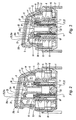
figures 1 sont des vues partielles d'un flacon équipé d'une pompe en position de repos selon un mode de réalisation de l'invention, respectivement en coupe longitudinale (figure 1a ) et en perspective coupée (figure 1b ) ; - les
figures 2 à 5 sont des vues partielles en coupe longitudinale du flacon selon lafigure 1 dans les différentes positions d'utilisation suivantes : en position d'ouverture de l'orifice (figure 2 ), en fin de course de distribution (figure 3 ), en position de fermeture de l'orifice (figure 4 ) et dans la course d'aspiration (figure 5 ).
Dans la description, les termes de positionnement dans l'espace sont pris en référence à la position de la pompe représentée sur les figures.
- the
figures 1 are partial views of a bottle equipped with a pump in the rest position according to one embodiment of the invention, respectively in longitudinal section (figure 1a ) and cut perspective (figure 1b ); - the
Figures 2 to 5 are partial views in longitudinal section of the bottle according to thefigure 1 in the following different operating positions: in the opening position of the orifice (figure 2 ), at the end of the distribution run (figure 3 ), in the closed position of the orifice (figure 4 ) and in the suction stroke (figure 5 ).
In the description, the spatial positioning terms are taken with reference to the position of the pump shown in the figures.
En relation avec les figures, on décrit un mode de réalisation d'une pompe montée sur un flacon de sorte à permettre la distribution d'un liquide contenu dans ledit flacon. Dans un exemple d'application, le liquide est un gel ou une crème, pour un usage cosmétique ou pour des traitements pharmaceutiques.In connection with the figures, there is described an embodiment of a pump mounted on a bottle so as to allow the distribution of a liquid contained in said bottle. In an exemplary application, the liquid is a gel or a cream, for cosmetic use or for pharmaceutical treatments.
Le flacon comprend un corps surmonté par une bague 1 sur laquelle la pompe est montée. En outre, un piston suiveur (non représenté) du liquide est monté coulissant dans le corps de sorte à amener le liquide dans ladite pompe en vue de sa distribution sans reprise d'air. Pour ce faire, le flacon comprend, à l'opposé de la pompe, un trou d'évent. Bien que la description soit faite en relation avec une distribution sans reprise d'air, la pompe suivant l'invention peut être utilisée avec d'autres types de distribution.The bottle comprises a body surmounted by a ring 1 on which the pump is mounted. In addition, a follower piston (not shown) of the liquid is slidably mounted in the body so as to bring the liquid into said pump for distribution without air intake. To do this, the bottle comprises, opposite the pump, a vent hole. Although the description is made in relation to a distribution without air intake, the pump according to the invention can be used with other types of distribution.
La pompe comprend une frette 2 solidarisée dans la bague 1 du flacon, ladite frette comprenant un orifice 3 de mise en communication de la pompe avec le liquide contenu dans le corps. Plus précisément, la frette 2 est montée de façon étanche sur la bague 1 avec l'orifice 3 en communication avec le liquide.The pump comprises a hoop 2 secured in the ring 1 of the bottle, said hoop comprising an
La frette 2 peut être réalisée par moulage d'un matériau plastique, notamment en polypropylène, et comprend un fond dans lequel l'orifice 3 est formé axialement. Par ailleurs, la frette 2 présente une géométrie cylindrique de révolution et, depuis le fond, s'étendent de façon concentrique :
- un manchon extérieur 4 dont une partie de la surface extérieure est emmanchée dans la bague 1 ;
- un manchon intérieur 5 dont l'extrémité inférieure est pourvue d'une butée 6 ; et
- un manchon central 7 sur la paroi inférieure duquel l'orifice de
distribution 3 est formé.
Par ailleurs, le flacon peut comprendre un capot destiné à être monté sur l'extérieur du manchon extérieur 4, au dessus de la partie emmanchée dans la bague 1.
- an outer sleeve 4, a portion of the outer surface is fitted in the ring 1;
- an
inner sleeve 5 whose lower end is provided with astop 6; and - a central sleeve 7 on the bottom wall of which the dispensing
orifice 3 is formed.
Furthermore, the bottle may comprise a cap intended to be mounted on the outside of the outer sleeve 4, above the portion fitted in the ring 1.
La pompe comprend un bouton poussoir 8 qui est pourvu d'un orifice d'éjection 9 du liquide, ledit bouton poussoir étant monté sur la frette 2 en translation contrainte par un moyen de rappel élastique formé d'un ressort 10. Plus précisément, le bouton poussoir 8 comprend une jupe pourvue de l'orifice 9 pour une éjection sensiblement radiale.The pump comprises a
La pompe comprend également un manchon doseur 11 qui est monté dans le bouton poussoir 8 pour être déplacé par lui sur la course de translation. Le manchon 11 est entouré par une jupe extérieure 12 qui comprend un rebord annulaire 13 coopérant avec une rainure 14 formée dans la jupe du bouton poussoir 8, de sorte à former zone d'association étanche entre ledit manchon et ledit bouton poussoir. En outre, l'association est fiabilisée par la formation d'une saillie 15 formée dans la jupe du bouton poussoir 8 pour maintenir en position ledit rebord dans ladite rainure.The pump also comprises a
Par ailleurs, la paroi radiale de liaison entre la jupe 12 et le manchon 11 forme surface de butée du ressort 10, ledit ressort étant en outre disposé autour du manchon intérieur 5 de la frette 2.Furthermore, the radial connecting wall between the
La pompe comprend également un piston doseur 16 qui comprend un canal 17 de distribution du liquide, ledit canal étant équipé d'un clapet de fermeture de l'orifice 3. Le piston doseur 16 présente une géométrie cylindrique de révolution, et peut être réalisé par moulage d'un matériau plastique.The pump also comprises a
Le piston 16 et le manchon 11 définissent entre eux une chambre de dosage du liquide et sont montés en translation étanche l'un par rapport à l'autre sur une course de distribution / aspiration du liquide. Pour ce faire, le manchon doseur 11 est monté en coulissement étanche dans un espace 18 formé entre les manchons intérieur 5 et central 7.The
Plus précisément, le manchon doseur 11 est en contact frottant sur des moyens d'étanchéité formés sur le piston 16, lesdits moyens comprenant une lèvre supérieure 19 et une lèvre inférieure 20 qui sont formées au voisinage de l'extrémité supérieure du piston 16. Cette réalisation permet d'améliorer l'étanchéité, notamment en prévoyant qu'une lèvre 19, 20 soit plaquée sur le manchon 11 dans chacun des sens de translation.More specifically, the
Dans le mode de réalisation représenté, le piston doseur 16 est fixé par emmanchement dans le manchon central 7, ledit emmanchement étant fiabilisé par la coopération d'une gorge 21 et d'une saillie 22 prévues respectivement sur le manchon 7 et dans le piston 16. Dans cette réalisation où le piston 16 est fixe, le clapet comprend une bille 23 qui est montée sur un siège formé sur l'orifice 3 de mise en communication, ledit siège étant pourvu de griffes 24 de limitation du déplacement ascendant de ladite bille. En particulier, l'utilisation d'une bille 23 permet d'atteindre une puissance d'aspiration du liquide qui est importante, notamment en ce qu'il est possible de cumuler les aspirations puisque l'air n'est pas réintroduit dans le flacon. Ainsi, il est possible de distribuer des liquides présentant une viscosité importante.In the embodiment shown, the
La pompe comprend en outre un pointeau 25 d'obturation de l'orifice d'éjection 9 qui, dans le mode de réalisation représenté, présente un bras 25a dont l'extrémité avant est pourvue d'une tête 25b d'obturation qui vient s'engager de façon étanche dans l'orifice d'éjection 9.The pump further comprises a needle 25 for closing off the
Le pointeau 25 est dissocié du manchon doseur 11, c'est-à-dire que ledit pointeau et ledit manchon sont réalisés en deux pièces distinctes, notamment par moulage. Outre la simplification de la réalisation des pièces, le pointeau 25 peut ainsi être réalisé en matériau plus ductile que celui formant le bouton poussoir 8, notamment en polyéthylène par rapport au polypropylène, de sorte à permettre une meilleure conformation de la tête 25b dans l'orifice 9.The needle 25 is dissociated from the
Par ailleurs, le déplacement du pointeau 25 peut alors être optimisé relativement à sa fonction d'étanchéification de l'orifice 9. En particulier, comme représenté sur les figures, la translation du pointeau 25 est réalisée suivant l'axe de l'orifice 9, de sorte à fiabiliser le centrage de la tête 25b dans ledit orifice et à améliorer le plaquage de ladite tête dans ledit orifice.Furthermore, the displacement of the needle 25 can then be optimized relative to its sealing function of the
Dans le mode de réalisation représenté, l'extrémité arrière du bras 25a est montée sur le manchon doseur 11 par l'intermédiaire d'une fourchette 26 dans laquelle un axe 27 formé latéralement de part et d'autre sur ledit pointeau est engagé. En outre, le pointeau 25 est monté sur le manchon doseur 11 par l'intermédiaire d'un dispositif de déplacement réversible dudit pointeau entre une position d'obturation et une position d'éjection, ledit dispositif étant actionné par interférence entre le manchon 11 et le piston 16 lors du déplacement du bouton poussoir 8 sur la frette 2.In the embodiment shown, the rear end of the arm 25a is mounted on the
Le pointeau 25 est disposé dans le volume étanche formé dans la partie supérieure du bouton poussoir 8, et plus précisément sous la paroi supérieure dudit bouton poussoir. En outre, le bouton poussoir 8 comprend des surfaces de guidage de la translation du pointeau 25 et une butée 28 pour ledit pointeau en position d'éjection. Sur les figures, le bouton présente une surface de guidage avant 29 formée au voisinage de l'orifice 9 et une surface de guidage arrière 30 qui est prolongée par la butée 28 pour former un logement pour l'extrémité arrière du pointeau 25.The needle 25 is disposed in the sealed volume formed in the upper part of the
Dans le mode de réalisation décrit, le manchon doseur 11 comprend un tube 31 creux qui est intégré à un corps du manchon 32 par l'intermédiaire du dispositif de déplacement, ledit corps étant monté en translation dans l'espace 18. Par ailleurs, le tube 31 est monté en coulissement dans le piston doseur 16 avec une interférence suffisante pour actionner ledit dispositif avant ou au début de la translation sur la course de distribution / aspiration. Pour ce faire, la périphérie du tube 31 est pourvue d'un jonc de coulissement 33 dans le canal, ledit jonc coopérant avec une butée 34 prévue dans le piston 16 de sorte à définir la fin de course supérieure du jonc 33 à l'intérieur du canal 17.In the embodiment described, the
Selon une réalisation, le dispositif de déplacement comprend au moins une biellette 35 qui est agencée pour permettre un déplacement réversible du corps 32 du manchon doseur 11 par rapport au tube 31, ledit dispositif étant en outre agencé pour transformer lesdits déplacements en translation du pointeau 25 relativement audit bouton poussoir dans une position respectivement d'éjection et d'obturation. En outre, la biellette 35 est pourvue des moyens de montage de la tige, c'est-à-dire de la fourchette 26 sur les figures.According to one embodiment, the displacement device comprises at least one
Dans le mode de réalisation représenté, le tube 31 est intégré au corps 32 du manchon doseur 11 par l'intermédiaire de deux biellettes 35 présentant chacune une articulation interne 35a et une articulation externe 35b avec respectivement le tube 31 et le corps 32. Sur les figures, les articulations sont réalisées par amincissement de matière.In the embodiment shown, the tube 31 is integrated in the
Par ailleurs, les biellettes 35 sont disposées, de part et d'autre du tube 31, suivant le plan contenant la direction de translation du pointeau 25, et l'extrémité arrière du bras 25a est montée sur la biellette 35 arrière. En outre, la biellette 35 arrière présente une surface supérieure inclinée qui est formée entre les mâchoires de la fourchette 26, de sorte à venir interférer avec le pointeau 25 en position d'éjection. Cette surface, éventuellement en combinaison avec la butée 28 formée dans le bouton 8, permet notamment de maintenir mécaniquement le pointeau 25 lorsqu'il est en position d'éjection, de sorte à limiter les contraintes subies par le dispositif de déplacement sur la course de distribution.Furthermore, the
En outre, une butée 36 est formée pour limiter le déplacement montant du tube 31 par rapport au corps 32, ladite butée étant formée dans le bouton poussoir 8 pour venir en appui sur ledit tube en fin de déplacement descendant du corps 32 (
En relation avec les figures, on décrit le fonctionnement de la pompe décrite ci-dessus. En position de repos (
Par appui sur le bouton poussoir 8 (
Dans la course de distribution et jusqu'à sa fin (
Sur la
Claims (16)
- Pump intended to be mounted on a bottle so as to allow the dispensing of a liquid contained in said bottle, said pump comprising:- a hoop (2) intended to be fixed to the bottle, said hoop comprising an orifice (3) for putting in communication with the liquid;- a push button (8) comprising an orifice (9) for ejecting the liquid, said push button being mounted on said hoop in translation restrained by an elastic return means (10);- a dosing sleeve (11) mounted in said push button and a dosing piston (16) mounted in said hoop, said dosing piston comprising a channel (17) for dispensing the liquid, said channel being equipped with a valve (23) for reversible closure of the orifice (3) for putting in communication, said sleeve and said piston defining between them a chamber for dosing the liquid and being mounted in sealed translation with respect to each other on a liquid dispensing/suction travel;said pump also comprising a needle (25) for closing the ejection orifice (9), said needle being mounted on said sleeve by means of a device for the reversible movement of said needle between a closure position and an ejection position, said device being actuated by interference between the sleeve (11) and the piston (16) when the push button (8) is moved on the hoop (2), said pump being characterised in that the closure needle (25) is separate from the dosing sleeve (11).
- Pump according to claim 1, characterised in that the dosing sleeve (11) comprises a tube (31) integrated in a body of the sleeve (32) by means of the movement device, said tube being mounted slideably in the dosing piston (16) with sufficient interference to actuate said device before or at the start of the translation over the dispensing/suction travel.
- Pump according to claim 2, characterised in that the movement device comprises at least one link (35) that is arranged to allow a reversible movement of the body of the sleeve (32) with respect to the tube (31), said device also being arranged to convert the said movements into translation of the needle (25) relative to said push button in a position respectively of ejection and closure, said link (35) being provided with means of mounting the needle (25).
- Pump according to claim 3, characterised in that the link (35) has an internal articulation (35a) and an external articulation (35b) with respectively the tube (31) and the body of the sleeve (32).
- Pump according to claim 4, characterised in that the tube (31) is integrated in the body of the sleeve (32) by means of two links (35) that are disposed, on each side of said tube, along the plane containing the translation direction of the needle (25).
- Pump according to claim 5, characterised in that the needle (25) comprises an arm (25a), the front end of which is provided with a closure head (25b), the rear end of said arm being mounted on the rear link (35).
- Pump according to any one of claims 1 to 6, characterised in that the needle (25) is mounted in the push button (8), the said button comprising surfaces (29, 30) for guiding the translation of the needle (25) and a stop (28) for said needle in the ejection position.
- Pump according to any one of claims 3 to 7, characterised in that a stop (36) is formed to limit the upward movement of the tube (31) with respect to the body of the sleeve (32).
- Pump according to claim 8, characterised in that the stop (36) is formed in the push button (8) in order to come into abutment on the tube (31) at the end of downward movement of the body of the sleeve (32).
- Pump according to any one claims 1 to 9, characterised in that the means of mounting the needle (25) comprise a fork (26) in which a spindle (27) formed on said needle is engaged.
- Pump according to any one of claims 1 to 10, characterised in that the hoop (2) comprises a central sleeve (7) in which the dosing piston (16) is fixed, the bottom wall of the said sleeve being provided with the orifice (3) for putting in communication.
- Pump according to claim 11, characterised in that the hoop (2) comprises an internal sleeve (5) surrounding the central sleeve (7), forming a space (18) in which the dosing sleeve (11) is mounted for sealed sliding.
- Pump according to claim 12, characterised in that the dosing sleeve (11) is in rubbing contact on sealing means (19, 20) formed on the piston (16).
- Pump according to any one of claims 1 to 13, characterised in that the valve comprises a ball (23) mounted on a seat formed on the orifice (3) for putting in communication.
- Bottle containing a liquid product, said bottle comprising a neck (1) on which the hoop (2) of a pump according to any one of claims 1 to 14 is mounted with the orifice (3) in communication with the liquid.
- Bottle according to claim 15, characterised in that it also comprises a follower piston that is slideably mounted in the bottle so as to bring the liquid into said pump with a view to its dispensing without taking up air.
Applications Claiming Priority (1)
| Application Number | Priority Date | Filing Date | Title |
|---|---|---|---|
| FR0707430A FR2922528B1 (en) | 2007-10-23 | 2007-10-23 | PUMP FOR DISPENSING A LIQUID CONTAINED IN A BOTTLE |
Publications (2)
| Publication Number | Publication Date |
|---|---|
| EP2052786A1 EP2052786A1 (en) | 2009-04-29 |
| EP2052786B1 true EP2052786B1 (en) | 2012-06-06 |
Family
ID=39521899
Family Applications (1)
| Application Number | Title | Priority Date | Filing Date |
|---|---|---|---|
| EP08290937A Active EP2052786B1 (en) | 2007-10-23 | 2008-10-06 | Pump for dispensing a liquid contained in a bottle |
Country Status (6)
| Country | Link |
|---|---|
| US (1) | US8028862B2 (en) |
| EP (1) | EP2052786B1 (en) |
| CN (1) | CN101417270B (en) |
| BR (1) | BRPI0804528A2 (en) |
| ES (1) | ES2388947T3 (en) |
| FR (1) | FR2922528B1 (en) |
Families Citing this family (20)
| Publication number | Priority date | Publication date | Assignee | Title |
|---|---|---|---|---|
| JP5223719B2 (en) * | 2009-02-18 | 2013-06-26 | 株式会社アドヴィックス | Piston pump |
| KR101025191B1 (en) * | 2009-03-03 | 2011-04-01 | (주)톨리코리아 | Nozzle Switchgear of Cosmetic Container |
| US8444019B2 (en) | 2009-08-07 | 2013-05-21 | Ecolab Usa Inc. | Wipe and seal product pump |
| FR2956098B1 (en) * | 2010-02-11 | 2012-03-30 | Airlessystems | FLUID PRODUCT DISPENSER. |
| DE202010009751U1 (en) * | 2010-07-01 | 2011-09-02 | Werner Holzmann | Dispensers |
| FR2970954B1 (en) * | 2011-01-27 | 2014-06-06 | Valois Sas | HEAD OF DISTRIBUTION OF FLUID PRODUCT. |
| US20120234866A1 (en) * | 2011-03-16 | 2012-09-20 | Jisong Lin | Foam pump with spring isolated from flow path |
| DE102011001534A1 (en) * | 2011-03-21 | 2012-09-27 | Rpc Bramlage Gmbh | Dispenser for dispensing liquid to pasty masses |
| DE202011000682U1 (en) * | 2011-03-24 | 2013-11-12 | Rpc Bramlage Gmbh | Dispenser for dispensing liquid to pasty masses |
| KR101219011B1 (en) * | 2011-07-08 | 2013-01-21 | (주)연우 | Dispenser pump button |
| CN102941967B (en) * | 2012-11-22 | 2016-04-13 | 中山环亚塑料包装有限公司 | Anti-theft structure pump head |
| US9206797B2 (en) | 2012-11-29 | 2015-12-08 | Meadwestvaco Calmar Netherlands Bv | Bellows for a pump device |
| US10113541B2 (en) | 2012-11-29 | 2018-10-30 | Silgan Dispensing Systems Netherlands B.V. | Valves and pumps using said valves |
| US20140145102A1 (en) * | 2012-11-29 | 2014-05-29 | Meadwestvaco Calmar Netherlands Bv | Valves and pumps using said valves |
| BE1021429B1 (en) * | 2013-02-28 | 2015-11-19 | Laboratoire Puressentiel Benelux Sa | HIGH DOSING SPRAYER |
| IT201600115319A1 (en) * | 2016-11-15 | 2018-05-15 | Lumson Spa | Dispensing device for a fluid substance |
| IT201700056451A1 (en) * | 2017-05-24 | 2018-11-24 | Lumson Spa | Container of fluid substances with hermetic closure system and method of use |
| EP3676017A1 (en) | 2017-09-01 | 2020-07-08 | BASF Coatings GmbH | Measuring and miixing devices |
| DE102019110454A1 (en) * | 2018-04-24 | 2019-10-24 | Gerhard Brugger | Dispensers |
| US11702255B2 (en) | 2021-04-20 | 2023-07-18 | Diversey, Inc. | Fluid container cap with dual-position restrictor |
Family Cites Families (13)
| Publication number | Priority date | Publication date | Assignee | Title |
|---|---|---|---|---|
| US4174056A (en) * | 1977-05-10 | 1979-11-13 | Ciba-Geigy Corporation | Pump type dispenser with continuous flow feature |
| US5429275A (en) * | 1991-07-02 | 1995-07-04 | Katz; Otto | Dispenser of doses of liquids and paste-like masses |
| IT1275561B (en) * | 1995-07-17 | 1997-08-07 | Ter | ATOMIZED LIQUID DISPENSER |
| KR200233932Y1 (en) * | 2001-01-22 | 2001-09-25 | 강성일 | Pumping Device And Cosmetic Spray Having The Same |
| JP2003008569A (en) * | 2001-06-26 | 2003-01-10 | O2 Interactive:Kk | Data relay device |
| EP1310437A1 (en) * | 2001-11-12 | 2003-05-14 | Mitani Valve Co | Dispenser |
| CA2468945C (en) * | 2001-11-30 | 2010-12-21 | Yoshino Kogyosho Co., Ltd. | A depression head for pump mechanism |
| DE10200593A1 (en) * | 2002-01-10 | 2003-07-31 | Aero Pump Gmbh | Actuating head of a suction-pressure pump for ejecting a product from a container |
| FR2838070B1 (en) * | 2002-04-04 | 2005-02-11 | Valois Sa | DISTRIBUTION HEAD TO BE MOUNTED ON A MOBILE HOLLOW ACTUATING ROD |
| EP1498142B1 (en) | 2002-04-10 | 2007-03-21 | Obschestvo S Organichennoy Otvetstvennostyu "Vitagel" | Polyfunctional biocompatible hydrogel and method for the production thereof |
| US7503466B2 (en) * | 2003-04-11 | 2009-03-17 | L'oreal | Pump and receptacle fitted therewith |
| EP1714706A3 (en) * | 2005-04-21 | 2009-12-09 | Steven Padar | Dosing pump and method for manufacturing such a filled dosing pump |
| FR2893314B1 (en) * | 2005-11-16 | 2007-12-21 | Rexam Dispensing Smt Soc Par A | ACTUATING AND DISPENSING HEAD FOR PUMP |
-
2007
- 2007-10-23 FR FR0707430A patent/FR2922528B1/en not_active Expired - Fee Related
-
2008
- 2008-10-06 ES ES08290937T patent/ES2388947T3/en active Active
- 2008-10-06 EP EP08290937A patent/EP2052786B1/en active Active
- 2008-10-22 CN CN2008101700918A patent/CN101417270B/en not_active Expired - Fee Related
- 2008-10-22 US US12/256,188 patent/US8028862B2/en not_active Expired - Fee Related
- 2008-10-23 BR BRPI0804528-3A patent/BRPI0804528A2/en not_active IP Right Cessation
Also Published As
| Publication number | Publication date |
|---|---|
| BRPI0804528A2 (en) | 2009-06-30 |
| US20090101677A1 (en) | 2009-04-23 |
| FR2922528A1 (en) | 2009-04-24 |
| EP2052786A1 (en) | 2009-04-29 |
| CN101417270A (en) | 2009-04-29 |
| US8028862B2 (en) | 2011-10-04 |
| FR2922528B1 (en) | 2010-03-26 |
| CN101417270B (en) | 2013-06-05 |
| ES2388947T3 (en) | 2012-10-22 |
Similar Documents
| Publication | Publication Date | Title |
|---|---|---|
| EP2052786B1 (en) | Pump for dispensing a liquid contained in a bottle | |
| EP1980332B1 (en) | Pump for dispensing a liquid contained in a bottle | |
| EP0623060B1 (en) | Improved precompression pump | |
| EP0757592B1 (en) | Improved precompression pump | |
| CA2121655C (en) | Liquid or paste product dosing dispenser | |
| EP2708286B1 (en) | Fillable vial for dispensing a fluid product | |
| EP1974830B1 (en) | Distribution nozzle comprising an axially attached sealing sleeve | |
| EP2719467B1 (en) | Refillable bottle of a fluid dispenser | |
| EP2689858B1 (en) | Sleeve for sealingly attaching a dispensing member onto the neck of a bottle containing a fluid product to be dispensed | |
| FR2836902A1 (en) | DISPENSING HEAD WITH MOBILE CANNULA FOR FITTING A PACKAGING AND DISPENSING DEVICE | |
| FR2854131A1 (en) | Refilling a spray applicator, e.g. for a liquid perfume/cosmetic/pharmaceutical product, empties the applicator to form an underpressure to draw in the product from an external reservoir | |
| EP2511196A1 (en) | Dispensing unit for a fluid provided with a filling valve | |
| EP2397422B1 (en) | Fluid dispensing system | |
| FR2692569A1 (en) | Dispenser filling procedure - uses shutter with cavity which contains single does of fluid and transfers it to dispenser | |
| EP1127013A1 (en) | Dispenser with peripheral delivery mode | |
| EP2734079B1 (en) | System for dispensing a fluid product packaged in a bottle | |
| EP1583613B1 (en) | Fluid product dispensing device | |
| FR2995226A1 (en) | SYSTEM FOR DISPENSING A FLUID PRODUCT FOAM | |
| EP1194247A1 (en) | Improved pre-compression spray pump | |
| EP1703985B1 (en) | Fluid product dispenser | |
| EP2062495B1 (en) | System for applying a doughy liquid product by twisting a flexible packaging bag | |
| FR2714119A1 (en) | Manual spray pump with adjustable delivery used for pharmaceutical, perfume or cosmetic products | |
| FR3139808A1 (en) | Refillable source and dispenser bottle | |
| FR2779185A1 (en) | pump for liquids or paste, |
Legal Events
| Date | Code | Title | Description |
|---|---|---|---|
| PUAI | Public reference made under article 153(3) epc to a published international application that has entered the european phase |
Free format text: ORIGINAL CODE: 0009012 |
|
| AK | Designated contracting states |
Kind code of ref document: A1 Designated state(s): AT BE BG CH CY CZ DE DK EE ES FI FR GB GR HR HU IE IS IT LI LT LU LV MC MT NL NO PL PT RO SE SI SK TR |
|
| AX | Request for extension of the european patent |
Extension state: AL BA MK RS |
|
| 17P | Request for examination filed |
Effective date: 20091020 |
|
| AKX | Designation fees paid |
Designated state(s): AT BE BG CH CY CZ DE DK EE ES FI FR GB GR HR HU IE IS IT LI LT LU LV MC MT NL NO PL PT RO SE SI SK TR |
|
| GRAP | Despatch of communication of intention to grant a patent |
Free format text: ORIGINAL CODE: EPIDOSNIGR1 |
|
| GRAS | Grant fee paid |
Free format text: ORIGINAL CODE: EPIDOSNIGR3 |
|
| GRAA | (expected) grant |
Free format text: ORIGINAL CODE: 0009210 |
|
| AK | Designated contracting states |
Kind code of ref document: B1 Designated state(s): AT BE BG CH CY CZ DE DK EE ES FI FR GB GR HR HU IE IS IT LI LT LU LV MC MT NL NO PL PT RO SE SI SK TR |
|
| REG | Reference to a national code |
Ref country code: GB Ref legal event code: FG4D Free format text: NOT ENGLISH |
|
| REG | Reference to a national code |
Ref country code: AT Ref legal event code: REF Ref document number: 560741 Country of ref document: AT Kind code of ref document: T Effective date: 20120615 Ref country code: CH Ref legal event code: EP |
|
| REG | Reference to a national code |
Ref country code: IE Ref legal event code: FG4D Free format text: LANGUAGE OF EP DOCUMENT: FRENCH |
|
| REG | Reference to a national code |
Ref country code: DE Ref legal event code: R096 Ref document number: 602008016160 Country of ref document: DE Effective date: 20120802 |
|
| REG | Reference to a national code |
Ref country code: NL Ref legal event code: VDEP Effective date: 20120606 |
|
| REG | Reference to a national code |
Ref country code: ES Ref legal event code: FG2A Ref document number: 2388947 Country of ref document: ES Kind code of ref document: T3 Effective date: 20121022 |
|
| PG25 | Lapsed in a contracting state [announced via postgrant information from national office to epo] |
Ref country code: SE Free format text: LAPSE BECAUSE OF FAILURE TO SUBMIT A TRANSLATION OF THE DESCRIPTION OR TO PAY THE FEE WITHIN THE PRESCRIBED TIME-LIMIT Effective date: 20120606 Ref country code: NO Free format text: LAPSE BECAUSE OF FAILURE TO SUBMIT A TRANSLATION OF THE DESCRIPTION OR TO PAY THE FEE WITHIN THE PRESCRIBED TIME-LIMIT Effective date: 20120906 Ref country code: CY Free format text: LAPSE BECAUSE OF FAILURE TO SUBMIT A TRANSLATION OF THE DESCRIPTION OR TO PAY THE FEE WITHIN THE PRESCRIBED TIME-LIMIT Effective date: 20120606 Ref country code: LT Free format text: LAPSE BECAUSE OF FAILURE TO SUBMIT A TRANSLATION OF THE DESCRIPTION OR TO PAY THE FEE WITHIN THE PRESCRIBED TIME-LIMIT Effective date: 20120606 Ref country code: FI Free format text: LAPSE BECAUSE OF FAILURE TO SUBMIT A TRANSLATION OF THE DESCRIPTION OR TO PAY THE FEE WITHIN THE PRESCRIBED TIME-LIMIT Effective date: 20120606 |
|
| REG | Reference to a national code |
Ref country code: AT Ref legal event code: MK05 Ref document number: 560741 Country of ref document: AT Kind code of ref document: T Effective date: 20120606 |
|
| REG | Reference to a national code |
Ref country code: LT Ref legal event code: MG4D Effective date: 20120606 |
|
| PG25 | Lapsed in a contracting state [announced via postgrant information from national office to epo] |
Ref country code: SI Free format text: LAPSE BECAUSE OF FAILURE TO SUBMIT A TRANSLATION OF THE DESCRIPTION OR TO PAY THE FEE WITHIN THE PRESCRIBED TIME-LIMIT Effective date: 20120606 Ref country code: HR Free format text: LAPSE BECAUSE OF FAILURE TO SUBMIT A TRANSLATION OF THE DESCRIPTION OR TO PAY THE FEE WITHIN THE PRESCRIBED TIME-LIMIT Effective date: 20120606 Ref country code: LV Free format text: LAPSE BECAUSE OF FAILURE TO SUBMIT A TRANSLATION OF THE DESCRIPTION OR TO PAY THE FEE WITHIN THE PRESCRIBED TIME-LIMIT Effective date: 20120606 Ref country code: GR Free format text: LAPSE BECAUSE OF FAILURE TO SUBMIT A TRANSLATION OF THE DESCRIPTION OR TO PAY THE FEE WITHIN THE PRESCRIBED TIME-LIMIT Effective date: 20120907 |
|
| PG25 | Lapsed in a contracting state [announced via postgrant information from national office to epo] |
Ref country code: AT Free format text: LAPSE BECAUSE OF FAILURE TO SUBMIT A TRANSLATION OF THE DESCRIPTION OR TO PAY THE FEE WITHIN THE PRESCRIBED TIME-LIMIT Effective date: 20120606 Ref country code: IS Free format text: LAPSE BECAUSE OF FAILURE TO SUBMIT A TRANSLATION OF THE DESCRIPTION OR TO PAY THE FEE WITHIN THE PRESCRIBED TIME-LIMIT Effective date: 20121006 Ref country code: CZ Free format text: LAPSE BECAUSE OF FAILURE TO SUBMIT A TRANSLATION OF THE DESCRIPTION OR TO PAY THE FEE WITHIN THE PRESCRIBED TIME-LIMIT Effective date: 20120606 Ref country code: RO Free format text: LAPSE BECAUSE OF FAILURE TO SUBMIT A TRANSLATION OF THE DESCRIPTION OR TO PAY THE FEE WITHIN THE PRESCRIBED TIME-LIMIT Effective date: 20120606 Ref country code: EE Free format text: LAPSE BECAUSE OF FAILURE TO SUBMIT A TRANSLATION OF THE DESCRIPTION OR TO PAY THE FEE WITHIN THE PRESCRIBED TIME-LIMIT Effective date: 20120606 Ref country code: SK Free format text: LAPSE BECAUSE OF FAILURE TO SUBMIT A TRANSLATION OF THE DESCRIPTION OR TO PAY THE FEE WITHIN THE PRESCRIBED TIME-LIMIT Effective date: 20120606 Ref country code: NL Free format text: LAPSE BECAUSE OF FAILURE TO SUBMIT A TRANSLATION OF THE DESCRIPTION OR TO PAY THE FEE WITHIN THE PRESCRIBED TIME-LIMIT Effective date: 20120606 |
|
| PG25 | Lapsed in a contracting state [announced via postgrant information from national office to epo] |
Ref country code: PT Free format text: LAPSE BECAUSE OF FAILURE TO SUBMIT A TRANSLATION OF THE DESCRIPTION OR TO PAY THE FEE WITHIN THE PRESCRIBED TIME-LIMIT Effective date: 20121008 Ref country code: PL Free format text: LAPSE BECAUSE OF FAILURE TO SUBMIT A TRANSLATION OF THE DESCRIPTION OR TO PAY THE FEE WITHIN THE PRESCRIBED TIME-LIMIT Effective date: 20120606 |
|
| PLBE | No opposition filed within time limit |
Free format text: ORIGINAL CODE: 0009261 |
|
| STAA | Information on the status of an ep patent application or granted ep patent |
Free format text: STATUS: NO OPPOSITION FILED WITHIN TIME LIMIT |
|
| BERE | Be: lapsed |
Owner name: REXAM DISPENSING SMT Effective date: 20121031 |
|
| PG25 | Lapsed in a contracting state [announced via postgrant information from national office to epo] |
Ref country code: DK Free format text: LAPSE BECAUSE OF FAILURE TO SUBMIT A TRANSLATION OF THE DESCRIPTION OR TO PAY THE FEE WITHIN THE PRESCRIBED TIME-LIMIT Effective date: 20120606 |
|
| 26N | No opposition filed |
Effective date: 20130307 |
|
| PG25 | Lapsed in a contracting state [announced via postgrant information from national office to epo] |
Ref country code: MC Free format text: LAPSE BECAUSE OF NON-PAYMENT OF DUE FEES Effective date: 20121031 |
|
| REG | Reference to a national code |
Ref country code: CH Ref legal event code: PL |
|
| GBPC | Gb: european patent ceased through non-payment of renewal fee |
Effective date: 20121006 |
|
| REG | Reference to a national code |
Ref country code: DE Ref legal event code: R097 Ref document number: 602008016160 Country of ref document: DE Effective date: 20130307 |
|
| REG | Reference to a national code |
Ref country code: IE Ref legal event code: MM4A |
|
| PG25 | Lapsed in a contracting state [announced via postgrant information from national office to epo] |
Ref country code: IE Free format text: LAPSE BECAUSE OF NON-PAYMENT OF DUE FEES Effective date: 20121006 Ref country code: GB Free format text: LAPSE BECAUSE OF NON-PAYMENT OF DUE FEES Effective date: 20121006 Ref country code: BE Free format text: LAPSE BECAUSE OF NON-PAYMENT OF DUE FEES Effective date: 20121031 Ref country code: CH Free format text: LAPSE BECAUSE OF NON-PAYMENT OF DUE FEES Effective date: 20121031 Ref country code: LI Free format text: LAPSE BECAUSE OF NON-PAYMENT OF DUE FEES Effective date: 20121031 Ref country code: BG Free format text: LAPSE BECAUSE OF FAILURE TO SUBMIT A TRANSLATION OF THE DESCRIPTION OR TO PAY THE FEE WITHIN THE PRESCRIBED TIME-LIMIT Effective date: 20120906 |
|
| PG25 | Lapsed in a contracting state [announced via postgrant information from national office to epo] |
Ref country code: MT Free format text: LAPSE BECAUSE OF FAILURE TO SUBMIT A TRANSLATION OF THE DESCRIPTION OR TO PAY THE FEE WITHIN THE PRESCRIBED TIME-LIMIT Effective date: 20120606 |
|
| PG25 | Lapsed in a contracting state [announced via postgrant information from national office to epo] |
Ref country code: TR Free format text: LAPSE BECAUSE OF FAILURE TO SUBMIT A TRANSLATION OF THE DESCRIPTION OR TO PAY THE FEE WITHIN THE PRESCRIBED TIME-LIMIT Effective date: 20120606 |
|
| PG25 | Lapsed in a contracting state [announced via postgrant information from national office to epo] |
Ref country code: LU Free format text: LAPSE BECAUSE OF NON-PAYMENT OF DUE FEES Effective date: 20121006 |
|
| REG | Reference to a national code |
Ref country code: FR Ref legal event code: CD Owner name: ALBEA LACROST, FR Effective date: 20140513 |
|
| REG | Reference to a national code |
Ref country code: DE Ref legal event code: R081 Ref document number: 602008016160 Country of ref document: DE Owner name: ALBEA LACROST, FR Free format text: FORMER OWNER: REXAM DISPENSING SMT, TOURNUS, FR Effective date: 20140514 |
|
| REG | Reference to a national code |
Ref country code: ES Ref legal event code: PC2A Owner name: ALBEA LACROST, SOCIETE PAR ACTIONS SIMPLIFIEE Effective date: 20140617 |
|
| PG25 | Lapsed in a contracting state [announced via postgrant information from national office to epo] |
Ref country code: HU Free format text: LAPSE BECAUSE OF FAILURE TO SUBMIT A TRANSLATION OF THE DESCRIPTION OR TO PAY THE FEE WITHIN THE PRESCRIBED TIME-LIMIT Effective date: 20081006 |
|
| REG | Reference to a national code |
Ref country code: FR Ref legal event code: CD Owner name: ALBEA LACROST, FR Effective date: 20150316 |
|
| REG | Reference to a national code |
Ref country code: FR Ref legal event code: PLFP Year of fee payment: 8 |
|
| REG | Reference to a national code |
Ref country code: FR Ref legal event code: PLFP Year of fee payment: 9 |
|
| REG | Reference to a national code |
Ref country code: FR Ref legal event code: PLFP Year of fee payment: 10 |
|
| REG | Reference to a national code |
Ref country code: DE Ref legal event code: R082 Ref document number: 602008016160 Country of ref document: DE Representative=s name: ADARES PATENT- UND RECHTSANWAELTE REININGER & , DE |
|
| REG | Reference to a national code |
Ref country code: FR Ref legal event code: PLFP Year of fee payment: 11 |
|
| PGFP | Annual fee paid to national office [announced via postgrant information from national office to epo] |
Ref country code: DE Payment date: 20241029 Year of fee payment: 17 |
|
| PGFP | Annual fee paid to national office [announced via postgrant information from national office to epo] |
Ref country code: FR Payment date: 20241025 Year of fee payment: 17 |
|
| PGFP | Annual fee paid to national office [announced via postgrant information from national office to epo] |
Ref country code: IT Payment date: 20241021 Year of fee payment: 17 Ref country code: ES Payment date: 20241104 Year of fee payment: 17 |