EP2052671A2 - Medical apparatus e.g. for bile or pancreatic duct - Google Patents
Medical apparatus e.g. for bile or pancreatic duct Download PDFInfo
- Publication number
- EP2052671A2 EP2052671A2 EP08018480A EP08018480A EP2052671A2 EP 2052671 A2 EP2052671 A2 EP 2052671A2 EP 08018480 A EP08018480 A EP 08018480A EP 08018480 A EP08018480 A EP 08018480A EP 2052671 A2 EP2052671 A2 EP 2052671A2
- Authority
- EP
- European Patent Office
- Prior art keywords
- treatment instrument
- medical device
- insertion portion
- bending
- external force
- Prior art date
- Legal status (The legal status is an assumption and is not a legal conclusion. Google has not performed a legal analysis and makes no representation as to the accuracy of the status listed.)
- Granted
Links
Images







Classifications
-
- A—HUMAN NECESSITIES
- A61—MEDICAL OR VETERINARY SCIENCE; HYGIENE
- A61B—DIAGNOSIS; SURGERY; IDENTIFICATION
- A61B1/00—Instruments for performing medical examinations of the interior of cavities or tubes of the body by visual or photographical inspection, e.g. endoscopes; Illuminating arrangements therefor
- A61B1/273—Instruments for performing medical examinations of the interior of cavities or tubes of the body by visual or photographical inspection, e.g. endoscopes; Illuminating arrangements therefor for the upper alimentary canal, e.g. oesophagoscopes, gastroscopes
- A61B1/2736—Gastroscopes
-
- A—HUMAN NECESSITIES
- A61—MEDICAL OR VETERINARY SCIENCE; HYGIENE
- A61B—DIAGNOSIS; SURGERY; IDENTIFICATION
- A61B1/00—Instruments for performing medical examinations of the interior of cavities or tubes of the body by visual or photographical inspection, e.g. endoscopes; Illuminating arrangements therefor
- A61B1/00064—Constructional details of the endoscope body
- A61B1/00071—Insertion part of the endoscope body
- A61B1/0008—Insertion part of the endoscope body characterised by distal tip features
- A61B1/00098—Deflecting means for inserted tools
-
- A—HUMAN NECESSITIES
- A61—MEDICAL OR VETERINARY SCIENCE; HYGIENE
- A61B—DIAGNOSIS; SURGERY; IDENTIFICATION
- A61B1/00—Instruments for performing medical examinations of the interior of cavities or tubes of the body by visual or photographical inspection, e.g. endoscopes; Illuminating arrangements therefor
- A61B1/00131—Accessories for endoscopes
- A61B1/00133—Drive units for endoscopic tools inserted through or with the endoscope
-
- A—HUMAN NECESSITIES
- A61—MEDICAL OR VETERINARY SCIENCE; HYGIENE
- A61B—DIAGNOSIS; SURGERY; IDENTIFICATION
- A61B1/00—Instruments for performing medical examinations of the interior of cavities or tubes of the body by visual or photographical inspection, e.g. endoscopes; Illuminating arrangements therefor
- A61B1/005—Flexible endoscopes
- A61B1/0051—Flexible endoscopes with controlled bending of insertion part
-
- A—HUMAN NECESSITIES
- A61—MEDICAL OR VETERINARY SCIENCE; HYGIENE
- A61B—DIAGNOSIS; SURGERY; IDENTIFICATION
- A61B1/00—Instruments for performing medical examinations of the interior of cavities or tubes of the body by visual or photographical inspection, e.g. endoscopes; Illuminating arrangements therefor
- A61B1/012—Instruments for performing medical examinations of the interior of cavities or tubes of the body by visual or photographical inspection, e.g. endoscopes; Illuminating arrangements therefor characterised by internal passages or accessories therefor
- A61B1/018—Instruments for performing medical examinations of the interior of cavities or tubes of the body by visual or photographical inspection, e.g. endoscopes; Illuminating arrangements therefor characterised by internal passages or accessories therefor for receiving instruments
Definitions
- the present invention relates to a medical apparatus including a first medical device with a bending portion which is provided in an insertion portion and which is bent by a driving force of a driving portion, and a second medical device with an external force applying portion that applies an external force to the insertion portion of the first medical device by means of the driving force of the driving portion so that the insertion portion can operate.
- ERCP endoscopic retrograde cholangio pancreatography
- treatment instruments any of various endoscopic treatment instruments such as a cannulation tube through a treatment instrument insertion tube cavity formed in the side surface of the distal end portion of the insertion portion. The operator then inserts the treatment instrument into the bile duct or the pancreatic duct.
- the operator uses what is called a treatment instrument raising table provided in the vicinity of the opening at the distal end of the treatment instrument insertion tube cavity.
- a raising angle of the treatment instrument raising table can be varied by a manual operation.
- varying the raising angle of the treatment instrument raising table allows a direction in which the treatment instrument is drawn out through the opening to be varied to easily guide the treatment instrument to the bile duct or the pancreatic duct.
- an endoscopic device 150 shown in Fig. 1 includes a sideward viewing endoscope 100 and an endoscopic treatment instrument 110.
- An opening 102a is formed at a distal end portion 102 of an insertion portion 101 of the sideward viewing endoscope 100.
- An insertion portion 111 of the endoscopic treatment instrument 110 for example, an imaging tube, a high-frequency treatment instrument, or a balloon catheter (hereinafter referred to as the treatment instrument insertion portion in order to distinguish this insertion portion from the insertion portion 101 of the sideward viewing endoscope 100) is drawn out through the opening 102a.
- the operator To draw out the treatment instrument insertion portion 111 through the opening 102a and then insert the treatment instrument insertion portion 111 through the bile duct, the operator performs a procedure described below.
- the operator performs a manual operation of operating a bending knob 104 provided on an operation portion 103 to bend a bending portion (not shown in the drawings), a manual operation of twisting the insertion portion 101, and the like.
- the distal end portion 102 is placed opposite a target site, for example, a duodenal papilla 120 in a desired condition.
- the operator draws out the treatment instrument insertion portion 111 into a body via a treatment instrument insertion channel (not shown in the drawings) formed in the insertion portion 101 of the sideward viewing endoscope 100 and via a treatment instrument raising table (hereinafter simply referred to as a raising table) 105 located in the vicinity of the opening 102a. Since the raising table 105 has not been raised yet, the treatment instrument insertion portion 111 is thus drawn out as shown by a dashed line or an alternate long and short dash line.
- the amount by which the treatment instrument insertion portion 111 is drawn out varies, for example, as shown by the dashed line and the alternate long and short dash line depending on the amount by which the treatment instrument insertion portion 111, positioned close to the operator's hands, is pushed in.
- the operator After drawing the treatment instrument insertion portion 111 into the body, the operator operates a raising table operation lever 106. Then, a raising wire (not shown in the drawings) inserted through the insertion portion 101 is pulled. An angle of the treatment instrument raising table 105 is varied in conjunction with this traction. That is, a direction in which the treatment instrument insertion portion 111 is drawn out is changed, for example, from one shown by the alternate long and short dash line to one shown by a solid line. Thus, a distal end 112 of the treatment instrument insertion portion 111 is placed opposite the duodenal papilla 120.
- the direction in which the treatment instrument insertion portion 111 is drawn out is toward a pancreatic duct 121.
- Introducing the treatment instrument insertion portion 111 into a bile duct 122 is thus difficult. Consequently, the operator makes adjustment such as an operation of the bending knob 104, provided on the operation portion 103, to introduce the treatment instrument insertion portion 111 into the bile duct 122.
- the operator needs to be skilled in order to perform the manual operation of placing the distal end portion 102 of the insertion portion 101 of the endoscope 100 opposite the duodenal papilla 120 and smoothly introducing the treatment instrument insertion portion 111 into the pancreatic duct 121 or the bile duct 122.
- Japanese Patent Application Laid-Open Publication No. 7-000350 proposes a driving mechanism for a treatment instrument which rotationally drives the raising table into a raising table housing portion in the endoscope distal end portion, the driving mechanism replacing the driving motor provided in the operation portion.
- the operator operates an inputting portion of the operation portion including switches or buttons to vary the angle of the raising table.
- a treatment instrument manipulator has recently been proposed in which the treatment instrument insertion portion includes a bending portion having a plurality of active joints in order to improve the operator's operability.
- Japanese Patent Application Laid-Open Publication No. 8-224241 discloses a medical manipulator that allows a driving actuator to drive a driving wire.
- the controller converts the position into a bending angle and rotation angle of a treatment portion to drive a bending driving actuator and a rotational driving actuator.
- the bending portion of the medical manipulator is bent to operate the treatment portion in the operator's desired direction.
- the operator can easily place the distal end of the treatment instrument opposite the treatment site by operating the joy stick.
- a sideward viewing endoscope 130 with an electric treatment instrument raising table and a medical manipulator 140 form an endoscopic device 150A.
- the operator's workability can be drastically improved.
- reference numeral 131 denotes a raising table angle instruction inputting portion.
- the operator tilts the raising table angle instruction inputting portion 131, for example, in the direction of arrow a.
- a driving motor 107 in the operation portion 103 is then driven to pull the raising wire (not shown in the drawings) inserted through the insertion portion 101.
- the raising table 132 is raised.
- reference numeral 141 denotes a joy stick for a bending operation provided in a treatment instrument operation portion 142.
- the joy stick 141 can be operationally tilted, for example, in the direction of arrow c, d, e, or f.
- driving actuators 143 and 144 in the treatment instrument operation portion 142 are driven.
- the bending potion 113 is bent, for example, as shown by an alternate one and two short dash line to enable a position of the distal end 112 to be changed.
- the raising table angle instruction inputting portion 131 and the joy stick 141 need to be operated. It is cumbersome for the operator alone to operate the raising table angle instruction inputting portion 131 and the joy stick 141. On the other hand, if the operator operates one of the raising table angle instruction inputting portion 131 and the joy stick 141 and an assistant operates the other, associating the two operations with each other is difficult.
- An object of the present invention is to provide a medical apparatus with high operability which can easily approach the target site without the need to operate the respective operation portions provided in a plurality of electrically operative medical devices.
- a medical apparatus comprises a first medical device, a second medical device, an integrated inputting device, and an integrated control device.
- the medical device comprises an insertion portion comprising a bending portion that is bent by a driving force of a first driving portion and a first control device drivingly controlling the first driving portion.
- the second medical device comprises an external force applying portion applying an external force to the insertion portion of the first medical device to move the insertion portion, a second driving portion generating a driving force allowing the external force applying portion to be operated, and a second control device drivingly controlling the second driving portion.
- the integrated inputting portion instructs a distal end of the insertion portion to be moved to a target position or a target posture or in a target direction, in a configuration in which the external force of the external force applying portion provided in the second medical device can be applied to the insertion portion of the first medical device.
- the integrated control device drivingly controls at least one of the first driving portion provided in the first medical device and the second driving portion provided in the second medical device on the basis of an instruction from the integrated inputting device.
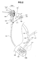
- a first embodiment of a medical apparatus will be described with reference to Figs. 3 to 28 .
- the medical apparatus will be described with reference to Figs. 3 to 11 .
- a medical apparatus 1 is composed of a medical manipulator (hereinafter simply referred to as a treatment instrument) 2 that is an active treatment instrument, a sideward viewing endoscope (hereinafter simply referred to as an endoscope) 3 with an active raising table (see reference numeral 35 in Figs. 6 and 7 ; hereinafter simply referred to as a raising table), and a treatment instrument controller 4, a raising table controller 5 and an integrated controller 6, and an integrated inputting device (hereinafter simply referred to as an inputting device) 7; the controllers and the inputting device are peripheral devices.
- the inputting device 7 includes, for example, an operationally tiltable operation lever 7a.
- the inputting device 7 is, for example, a joy stick and is operationally tiltable in any direction using a base portion of an operation lever 7a as a support point.
- the operation lever 7a is operationally tiltable in the direction of arrow F that is a Ya axis direction in an Oa coordinate system shown in the figures, the direction of arrow B that is a -Ya axis direction, the direction of arrow L that is a Za axis direction, and the direction of arrow R that is a -Za axis direction.
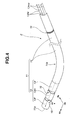
- the treatment instrument 2 is a first medical device and includes a treatment instrument insertion portion 11 and a bending driving portion 12.
- the bending driving portion 12 contains driving actuators 17 and 18 described below and which are first driving portions.
- the treatment instrument 2 is an imaging tube, a high-frequency treatment instrument, a balloon catheter, and the like.
- the treatment instrument insertion portion 11 includes a distal bending portion 13 and a flexible tube portion 14.
- the flexible tube portion 14 has a tend-to-curve portion 14a that is presetting means.
- the tend-to-curve portion 14a is configured to bend at a predetermined radius in a predetermined direction.
- the tend-to-curve portion 14a of the flexible tube portion 14 is positioned on a proximal end side of the distal bending portion 13.
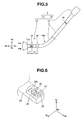
- the bending shape of the tend-to-curve portion 14a substantially matches a direction in which a first joint 15 described below rotates.
- the distal bending portion 13 forms a distal end side of the treatment instrument insertion portion 11.
- the distal bending portion 13 includes, for example, a distal bending piece 13f, a central bending piece 13m, a proximal bending piece 13r.
- the distal bending piece 13f and the central bending piece 13m are coupled together by the first joint 15 so as to be pivotally movable.
- the central bending piece 13m and the proximal bending piece 13r are coupled together by a second joint 16 so as to be pivotally movable.
- the first joint 15 is pivotally movable with respect to a Zb axis orthogonal to an Xb axis in an Ob coordinate system in the figures.
- the second joint 16 is pivotally movable with respect to a Yb axis in the Ob coordinate system.
- the Xb axis in the Ob coordinate system is parallel to a major axis shown by a dashed line.
- the distal bending piece 13f coupled to the central bending piece 13m by the first joint 15, is configured to rotate through an angle Y ⁇ b in the Yb axis direction and through an angle -Y ⁇ b in the -Yb axis direction, with respect to the Xb axis as shown in Fig. 5 .
- a first end and a second end of a distal bending piece wire 13fw are fixed to predetermined positions of the distal bending piece 13f.
- a central portion of the distal bending piece wire 13fw is fixedly disposed on a pulley (not shown in the drawings) provided in a bending driving portion 12.
- the pulley is pivotally moved by a first driving actuator 17, provided in the bending driving portion 12.
- a first driving actuator 17 When the first driving actuator 17 is driven to rotate the pulley, for example, clockwise, a first end of the distal bending piece wire 13fw is pulled, a second end is loosened.
- the distal bending piece 13f rotates through, for example, the angle Y ⁇ b.
- the first driving actuator 17 is driven to rotate the pulley counterclockwise, the second end of the distal bending piece wire 13fw is pulled, while the first end is loosened.
- the distal bending piece 13f rotates through an angle -Y ⁇ b.
- the central bending piece 13m coupled to the proximal bending piece 13r by the second joint 16, is configured to rotate through an angle Z ⁇ b in the Zb axis direction and through an angle -Z ⁇ b in the -Zb axis direction, with respect to the Xb axis direction.
- a first end and a second end of a central bending piece wire 13mw are fixed to predetermined positions of the central bending piece 13m.
- the Zb axis direction is a direction away from the reader, and the - Zb axis direction is a direction toward the reader.
- Reference numeral 19 shown in Figs. 4 and 5 denotes a projection amount detection mark (hereinafter simply referred to as a mark).
- the mark 19 is presetting means and is composed of, for example, a band-like peripheral line. Alignment of the mark 19 with an opening end in a treatment instrument insertion port 32 described below indicates that the distal end 11a of the treatment instrument insertion portion 11 is drawn out, by a predetermined amount, from an opening 34a in a raising table arrangement space (reference numeral 34 in Fig. 6 ; hereinafter simply referred to as a table space) provided in a distal end portion 24, described below, of the endoscope 3.
- a raising table arrangement space reference numeral 34 in Fig. 6 ; hereinafter simply referred to as a table space
- a central portion of the central bending piece wire 13mw is fixedly disposed on the pulley (not shown in the drawings) provided in the bending driving portion 12.
- the pulley is pivotally moved by a second driving actuator 18, provided in the bending driving portion 12.
- a second driving actuator 18 When the second driving actuator 18 is driven to rotate the pulley, for example, clockwise, a first end of the central bending piece wire 13mw is pulled, a second end is loosened.
- the central bending piece 13m rotates through, for example, the angle Z ⁇ b.
- the second driving actuator 18 is driven to rotate the pulley counterclockwise, the second end of the central bending piece wire 13mw is pulled, while the first end is loosened.
- the central bending piece 13m rotates through an angle -Z ⁇ b.
- a distance from a distal end surface of the treatment instrument insertion portion 11 to the first joint 15 is preset to L1.
- a distance from the first joint 15 to the second joint 16 is preset to L2.
- the bending pieces 13f, 13m, and 13r are covered with, for example, an outer tube without being exposed.
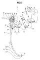
- the endoscope 3 shown in Fig. 3 includes an insertion portion 21, an operation portion 22, and a universal cord 23.
- the insertion portion 21 is inserted into a body.
- the operation portion 22 is provided at a proximal end side of the insertion portion 21.
- the universal cord 23 extends from the operation portion 22.
- the universal cord 23 includes an endoscope connector (not shown in the drawings) at a proximal end portion thereof.
- the endoscope connector is connected to a light source device that supplies illumination light, for example, via an illumination window described below.
- An image cable extending from the endoscope connector is connected to a camera control unit (not shown in the drawings).
- the camera control unit includes an image processing circuit that generates a video signal from an image signal resulting from photoelectric conversion by an image pickup device (not shown in the drawings) provided in the distal end portion of the endoscope 3.
- the video signal generated by the camera control unit is outputted to the display device. When the video signal is outputted to the display device, an endoscopic image is displayed on the screen of the display device.
- the insertion portion 21 is composed of a rigid distal end portion 24, a bending portion 25 that is, for example, bendable upward, downward, rightward, and leftward, and an elongate flexible tube portion 26; the distal end portion 24, the bending portion 25, and the flexible tube portion 26 are connected together in this order from the distal end side.
- the operation portion 22 also serves as a gripping portion.
- the operation portion 22 has a vertical bending knob 27 that bends the bending portion 25 in a vertical direction, a lateral bending knob 28 that bends the bending portion in a lateral direction, an air or water supply button 29, a suction button 30, a plurality of remote buttons 31, and the like.
- the remote buttons 31 give instructions on, for example, driving control of an image pickup unit or the like (not shown in the drawings) provided in the distal end portion 24.
- Reference numeral 31 a denotes a raising table angle instruction inputting portion that is a second inputting portion.
- the operation portion 22 has a treatment instrument insertion port 32 forming a proximal end portion of the treatment instrument channel described below (see reference numeral 33 in Fig. 7 ).
- the treatment instrument 2 is adapted to be drawn out through the opening 34a in the distal end portion 24 via the treatment instrument insertion port 32, the treatment instrument channel 33, and the raising table 35.
- Reference numeral 38 denotes a driving motor.
- the driving motor 38 is a second driving portion and moves the raising wire (not shown in the drawings) forward and backward, which operationally raises the raising table 35.
- Reference numeral 39 denotes an electric connection port.
- a connector 9c provided on a second connection cord 9b is removably connected to the connection port 39. Connecting the connector 9c to the connection port 39 allows the endoscope 3 to be electrically connected to the raising table controller 5.
- the endoscope 3 is a second medical device.
- the distal end portion 24 includes the raising table 35, an observation window 36 forming an observing optical system, and an illumination window 37 forming an illuminating optical system.
- the raising table 35 is an external force applying portion and is pivotally movably located in the table space 34, formed in the distal end portion 24.
- the distal opening 33a in the treatment instrument channel 33 communicates with the table space 34.
- the raising table 35 has an initial position in which a bottom side surface 35b of the raising table 35 abuts against a bottom surface 34b of the table space 34.
- the raising table 35 is configured to be pivotally movable with respect to the distal end portion 24 by a raising joint 40.
- An end portion of the raising wire (not shown in the drawings) is fixed to a predetermined position of the raising table 35.
- the raising table 35 is pivotally movable with respect to a Zc axis that is orthogonal to an Xc axis of the Oc coordinate system.
- the raising table 35 is configured to rotate through an angle Y ⁇ c in a Yc axis direction with respect to the Xc axis.
- the Xc axis in the Oc coordinate system is parallel to a treatment instrument guiding direction in which the treatment instrument 2 is drawn out when the raising table 35 is located in the initial position.
- the raising angle of the raising table 35 is varied in increments of the angle Y ⁇ c, for example, as shown by a dashed line.
- the raising table 35 moves gradually toward the initial position as the raising wire loosens.
- a channel hole 33b forming the treatment instrument channel 33 is formed in the distal end portion 24.
- a cap 33e is fixedly disposed on a proximal end side of the channel hole 33b.
- a distal end portion of a channel tube 33d is fixedly disposed on the cap 33e.
- a curving portion 33c shaped to be bent at a predetermined radius is formed on the distal opening 33a side of the channel hole 33b.
- the curving portion 33c is presetting means.
- a direction in which the curving portion 33c is bent substantially matches a direction in which the raising joint 40 rotates.
- a bending shape of the curving portion 33c substantially matches a bending shape of the tend-to-curve portion 14a of the flexible tube portion 14, forming the treatment instrument insertion portion 11.
- the mark 19 aligns with the opening end of the treatment instrument insertion port 32 to place the tend-to-curve portion 14a on the curving portion 33c.
- the treatment instrument insertion portion 11 is drawn out of the opening 34a in the endoscope 3 at a preset posture.
- a distance between the raising joint 40 and the second joint 16 is preset to L3.
- a rotating direction of the first joint 15 is preset to be the same as that of the raising joint 40. This is because the Ob coordinate system for the first joint 15 substantially matches the Oc coordinate system for the raising joint 40.
- the configuration in which the curving potion 33c is formed in the channel hole 33b is illustrated.
- a tend-to-curve portion corresponding to the tend-to-curve portion 14a of the flexible tube portion 14 is provided on the distal opening 33a side of the channel tube 33d.
- the bending portion 25 is bent in the vertical direction and the lateral direction.
- the upward direction corresponds to a Yo axis direction in an Oo coordinate system shown in Figs. 6 and 7 .
- the downward direction corresponds to a -Yo axis direction that is opposite to the Yo axis direction.
- the rightward direction corresponds to a Zo axis direction in the Oo coordinate system.
- the leftward direction corresponds to a -Zo axis direction that is opposite to the Zo axis direction.
- the Zo axis direction is a direction away from the reader
- the -Zo axis direction is a direction toward the reader.
- the treatment instrument controller 4 shown in Fig. 1 is a first control device.
- the treatment instrument controller 4 includes a control portion 4a.
- the control portion 4a controls driving of the actuators 17 and 18 of the treatment instrument 2 to move the distal end 11a in the vertical direction or the lateral direction.
- the treatment instrument controller 4 is electrically connected to the bending driving portion 12 via the first connection cord 9a.
- the inputting device 7 can be connected to the treatment instrument controller 4.
- the distal end 11a can be moved in the vertical direction, the lateral direction, or a synthesis direction of the vertical and lateral directions.
- the first driving actuator 17 provided in the treatment instrument 2
- the distal bending piece 13f located parallel to the Xb axis, rotates in the Yb axis direction in association with an angle through which the operation lever 7a has been tilted.
- the first driving actuator 17 is driven to rotate the distal bending piece 13f in the - Yb axis direction in association with the angle through which the operation lever 7a has been tilted.
- the second driving actuator 18 when the operator operationally tilts the operation lever 7a in the direction of arrow R, the second driving actuator 18 is driven to rotate the central bending piece 13m located parallel to the Xb axis, in the Zb axis direction in association with the angle through which the operation lever 7a has been tilted.
- the second driving actuator 18 when the operator operationally tilts the operation lever 7a in the direction of arrow L, the second driving actuator 18 is driven to rotate the central bending piece 13m in the -Zb axis direction in association with the angle through which the operation lever 7a has been tilted.
- the raising table controller 5 is a second control device.
- the raising table controller 5 includes a control portion 5a.
- the control portion 5a controls driving of the driving motor 38, provided in the endoscope 3, to vary the raising angle of the raising table 35.
- the raising table controller 5 is electrically connected to the driving motor 38 in the operation portion 22 via the second connection cord 9b.
- the inputting device 7 can also be connected to the raising table controller 5.
- the raising table 35 can be operated by connecting the inputting device 7 to the raising table controller 5, and in this state, operationally tilting the operation lever 7a of the inputting device 7 in the direction of arrow F or arrow B.
- the driving motor 38 provided in the endoscope 3 is driven to pull the raising wire inserted through the insertion portion 21. Then, the raising table 35 rotates in the Yc axis direction in association with the angle through which the operation lever 7a has been tilted. In contrast, when the operator operationally tilts the operation lever 7a of the inputting device 7 in the direction of arrow B, the driving motor 38 is driven in the opposite direction.
- the raising table 35 rotates in the -Yc axis direction as the raising wire loosens. If the bottom side surface 35b of the raising table 35 abuts against the bottom surface 34b of the table space 34 when the operator operationally tilts the operation lever 7a in the direction of arrow B, the driving motor 38 remains stopped.
- the integrated controller 6 is an integrated control device.
- the integrated controller 6 includes a control portion 6a.
- the integrated controller 6 is combined with the inputting device 7 to constitute an integrated medical device 8. That is, with the treatment instrument controller 4 and the raising table controller 5 connected to the integrated medical device 8, the control portion 6a drivingly controls the actuators 17 and 18, provided in the treatment instrument 2, and the driving motor 38 provided in the endoscope 3.
- the control portion 6a drives at least one of the first driving actuator 17 and the driving motor 38.
- the control portion 6a drives the second driving actuator 18.
- the inputting device 7 when the inputting device 7, the treatment instrument controller 4, and the raising table controller 5 are connected to the integrated controller 6, the function of the raising table angle instruction inputting portion 31a and the function of a joy stick 12a are off; the raising table angle instruction inputting portion 31a is provided in the endoscope 3, and the joy stick 12a is shown by a dashed line and is a first inputting portion provided in the bending driving portion 12.
- the treatment instrument controller 4 and the integrated controller 6 are connected together by a first signal cable 9d.
- the raising table controller 5 and the integrated controller 6 are connected together by a second signal cable 9e.
- the connection between the treatment instrument controller 4 and the integrated controller 6 and the connection between the raising table controller 5 and the integrated controller 6 may be established by one type of signal cable rather than by the separate signal cables.
- a medical staff member (hereinafter referred to as a staff member) performs an operation of connecting the treatment instrument controller 4 and the bending driving portion 12 of the treatment instrument 2, an operation of connecting the raising table controller 5 and the endoscope 3 together, an operation of connecting the treatment instrument controller 4 to the integrated controller 6, an operation of connecting the raising table controller 5 to the integrated controller 6, and an operation of connecting the inputting device 7 to the integrated controller 6.
- a staff member performs an operation of connecting the treatment instrument controller 4 and the bending driving portion 12 of the treatment instrument 2, an operation of connecting the raising table controller 5 and the endoscope 3 together, an operation of connecting the treatment instrument controller 4 to the integrated controller 6, an operation of connecting the raising table controller 5 to the integrated controller 6, and an operation of connecting the inputting device 7 to the integrated controller 6.
- the medical apparatus 1 is constructed.
- the operator appropriately performs an operation of bending the bending portion 25 using the bending knobs 27 and 28, an operation of twisting the insertion portion 21, and the like.
- the operator guides the distal end portion 24 to the vicinity of an opening in the papilla.
- the operator instructs the staff member to use the treatment instrument 2.
- the staff member inserts the distal end 11a of the treatment instrument insertion portion 11 of the treatment instrument 2 through the treatment instrument insertion port 32.
- the staff member pushes in the treatment instrument insertion portion 11.
- the treatment instrument insertion portion 11 is inserted through the channel tube 33d with a proximal end in communication with the treatment instrument insertion port 32.
- the tend-to-curve portion 14a of the flexible tube portion 14 abuts against the treatment instrument insertion port 32.
- the staff member continues to push in the treatment instrument insertion portion 11 against the elastic force of the tend-to-curve portion 14a.
- the tend-to-curve portion 14a is then deformed and passes through the treatment instrument insertion port 32.
- the tend-to-curve portion 14a is then inserted through the channel tube 33d.
- one side portion of the tend-to-curve portion 14a contacts an inner surface of the channel tube 33d by the elastic force.
- the staff member further pushes the distal end 11a of the treatment instrument insertion portion 11 toward the distal opening 33a.
- the staff member checks whether or not the projection amount detection mark 19 has reached the vicinity of the opening end of the treatment instrument insertion port 32.
- the staff member's push-in operation fits the tend-to-curve portion 14a into the curving portion 33c.
- the treatment instrument insertion portion 11 is drawn out of the endoscope 3 in a preset posture.
- the distal end 11a of the treatment instrument insertion portion 11 and a part of the distal bending portion 13 are displayed on the screen of the display device in a given posture.
- the treatment instrument insertion portion 11 is rotated around the major axis so that the positional energy of the tend-to-curve portion 14a is minimized as the projection amount detection mark 19 approaches the opening end of the treatment instrument insertion port 32.
- the treatment instrument insertion portion I 1 is rotated around the major axis so that the bending shape of the tend-to-curve portion 14a substantially matches the bending shape of the curving portion 33c as the tend-to-curve portion 14a approaches the curving portion 33c.
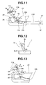
- a state in which the treatment instrument insertion portion 11 is drawn out of the endoscope 3 in the preset posture is considered to be a state in which a treatment instrument insertion portion 11A having a distal bending portion 13A including the three joints 15, 16, and 40 is drawn out of the endoscope 3 as shown in Fig. 11 .
- Two of the three joints 15, 16, and 40, that is, the joints 15 and 40, are configured to rotate in the same direction.
- the operator Upon determining that the treatment instrument insertion portion 11 has been drawn out of the endoscope 3 in the preset posture, the operator operates the operation lever 7a of the inputting device 7 to guide the distal end 11a of the treatment instrument insertion portion 11 to the opening in the papilla.
- a target bending direction and a target angle are inputted to the control portion 6a of the integrated controller 6.
- the control portion 6a controls the joints 15, 16, and 40 according to a control method described below, to achieve the target bending direction and the target angle.
- Positional information outputted by an encoder, a potentiometer, or the like provided in each of the driving actuators 17 and 18 and the driving motor 38 is inputted to the integrated controller 6. Then, the control portion 6a uses the positional information to control the joints 15, 16, and 40 in association with the operation of the operation lever 7a.
- control portion 6a A first example of control performed by the control portion 6a will be described with reference to Figs. 12 and 13 .
- the operator operationally tilts the operation lever 7a in the Ya axis direction, that is, the direction F, through an angle a with respect to the Xa axis.
- the control portion 6a operates the joints 15 and 40 on the basis of a preset ratio of, for example, r1:r2.
- the control portion 6a of the integrated controller 6 outputs control signals to the control portion 4a of the treatment instrument controller 4 and the control portion 5a of the raising table controller 5. Then, as shown in Fig. 13 , the control portion 5a rotates the raising joint 40 through a rotation angle ⁇ 1, and the control portion 4a rotates the joint 15 through a rotation angle ⁇ 3.
- the rotation angle ⁇ 1 (r1/(r1+r2)) ⁇
- the rotation angle ⁇ 3 (r2/(r1+r2)) ⁇ .
- the distal bending portion 13A in a preset posture shown by a dashed line is bent.
- the distal end 11a of the treatment instrument insertion portion 11 is moved in a target bending direction through a target angle; the target bending direction and the target angle are specified by the tilting operation of the operation lever 7a.
- the control portion 6a operates the joints 15 and 40 on the basis of a preset ratio, that is, the ratio of the tilting angle ⁇ of the operation lever 7a to a maximum bending angle ⁇ max of the operation lever 7a.
- the control portion 6a of the integrated controller 6 outputs control signals to the control portion 4a of the treatment instrument controller 4 and the control portion 5a of the raising table controller 5. Then, as shown in Fig. 15 , for example, the control portion 5a rotates the raising table joint 40 through the rotation angle ⁇ 1.
- the control portion 4a rotates the joint 15 through the rotation angle ⁇ 3.
- the rotation angle ⁇ 1 ( ⁇ / ⁇ max) ⁇ 1max
- the rotation angle ⁇ 3 ( ⁇ / ⁇ max) ⁇ 3max.
- ⁇ 1max denotes the maximum bending angle of the raising joint 40
- ⁇ 3max denotes the maximum bending angle of the joint 15.
- the distal bending portion 13A is bent from a preset posture shown by a dashed line.
- the distal end 11a of the treatment instrument insertion portion 11 is moved in a target bending direction through a target angle; the target bending direction and the target angle are specified by the tilting operation of the operation lever 7a.
- the second joint 16 is rotated in the direction in which the operation lever 7a has been tilted, in association with the tilting angle of the operation lever 7a.
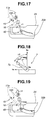
- control portion 6a A third example of control performed by the control portion 6a will be described with reference to Figs. 16 to 19 .
- the control portion 6a first determines whether or not the angle ⁇ 1 is greater than ⁇ 1 max.
- control portion 6a determines that an angle ⁇ 2 is greater or equal to ⁇ 1max as shown in Fig. 18 .
- the control portion 6a obtains an angle ⁇ 3 that is a difference between the angle ⁇ 2 and ⁇ 1max.
- the control portion 6a outputs control signals to the control portion 4a of the treatment instrument controller 4 and the control portion 5a of the raising table controller 5.
- the control portion 5a rotates the raising joint 40 through ⁇ 1 max.
- the distal bending portion 13A is bent from a preset posture shown by a dashed line.
- the distal end 11a of the treatment instrument insertion portion 11 is moved in a target bending direction through a target angle; the target bending direction and the target angle are specified by the tilting operation of the operation lever 7a.
- the second joint 16 is rotated in the direction in which the operation lever 7a has been tilted, in association with the tilting angle of the operation lever 7a.
- control can be performed according to the direction and angle specified by the inputting device such that the raising table of the endoscope and the treatment instrument bending portion are electrically driven in conjunction with each other to achieve wide ranges of target directions and target angles by means of simpler operations.
- the electric driving portions provided in the two medical devices can be controlled as an electric driving portion provided in one medical device.
- the treatment instrument insertion portion of the treatment instrument has the tend-to-curve portion of the predetermined shape.
- the treatment instrument channel of the endoscope has the curving portion with the shape matching the shape of the tend-to-curve portion.
- a relationship between the joint in the distal bending portion of the treatment instrument insertion portion and the joint in the raising table can be preset to allow the inputting device to be operated with a relationship maximizing the movable range, a relationship for a direction requiring the maximum bending angle, and the like always maintained in the same state.
- the integrated controller 6 may have a switch to allow one of a plurality of operation states to be selected. For example, one of three operation states described below may be selected using the switch.
- a first operation state the medical device including the distal bending portion 13 and the medical device including the raising table 35 can be drivingly controlled by operationally tilting the operation lever 7a.
- a second operation state only the medical device including the distal bending portion 13 can be drivingly controlled by operationally tilting the operation lever 7a.
- the medical device including the raising table 35 can be drivingly controlled by operationally tilting the operation lever 7a. According to this configuration, when the operator appropriately operates the switch during operation, the distal end 11a of the treatment instrument insertion portion 11 can be more easily bent into a target site.
- the inputting device 7, connected to the integrated controller 6 forming the integrated medical device 8, is provided separately from the endoscope 3 and the like as a joy stick.
- the inputting device 7 is not limited to the device separate from the endoscope 3.
- the inputting device 7 may be provided in the operation portion 22 of the endoscope 3. This configuration allows the operator's hand gripping the operation portion 22 to also operate the joy stick, drastically improving operability.
- the inputting device 7 is not limited to the joy stick but may be a track ball or the like.
- the inputting device 7, the treatment instrument controller 4, and the raising table controller 5 are connected to the integrated controller 6, forming the integrated medical device 8.
- the control portion of the integrated controller may have the function of the control portion 4a of the treatment instrument controller 4 and the function of the control portion 5a of the raising table controller 5.
- the single integrated controller can be used instead of the controllers for the medical apparatus, thus simplifying the medical apparatus. This also eliminates the need to connect the controllers together and allows the single integrated controller to directly control the rotation of the distal bending portion of the treatment instrument insertion portion and the rotation of the raising table.
- the actuator bending the joint may be an ultrasound actuator, a piezoelectric actuator, a magnetostrictive actuator, a polymer actuator, a fluid pressure actuator using air, water, or the like, or a shape memory alloy or an artificial muscle.
- the degree of freedom of the raising table, and the degree of freedom of the distal bending portion provided in the treatment instrument insertion portion is not limited to those described above in the embodiment. Different degrees of freedom may be used for the raising table and the distal bending portion.
- the bending structure of the distal bending portion may be a structure in which three or more bending pieces are consecutively connected together so as to be pivotally movable.
- the ratio of bending driving of the raising table to bending driving of the distal bending portion of the treatment instrument insertion portion is not limited to the preset ratio.
- a setting portion may be provided in the integrated controller so as to be able to vary the ratio.
- the endoscope is not limited to the sideward viewing endoscope but may be a forward viewing endoscope in which an observing optical system is located forward in the major axis direction, a rigid endoscope, or the like.
- a raising table 35A including the joint 40 may be provided in a forward viewing endoscope 3A including a forward viewing window 36A.
- the forward viewing endoscope 3A has a distal end portion 24A, a bending portion 25A, and an insertion portion 21A including a flexible tube portion (not shown in the drawings).
- a channel hole 33b, a channel tube 33d, and a cap 33e which form a treatment instrument channel 33A is provided in the insertion portion 21A.
- the channel hole 33b has a curving portion 33c corresponding to a tend-to-bend portion 14a provided in the treatment instrument insertion portion 11.
- a proximal end side of the treatment instrument insertion portion 11 includes the projection amount detection mark 19.
- the raising table 35A may be provided in an over tube rather than in the endoscope.
- the direction of rotation, around the major axis, of the treatment instrument insertion portion projecting from a distal surface of the frontward viewing endoscope and the amount of projection of the treatment instrument insertion portion can be matched with a preset state.
- the relationship between the joint in the distal bending portion of the treatment instrument insertion portion and the joint in the raising table can be preset to allow the inputting device to be operated with the relationship maximizing the movable range, the relationship for the direction requiring the maximum bending angle, and the like always maintained in the same state.
- the presetting means corresponds to the tend-to-curve portion 14a, the curving portion 33c, and the projection amount detection mark 19.
- the presetting means is not limited to the tend-to-curve portion 14a, the curving portion 33c, and the projection amount detection mark 19.
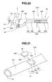
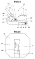
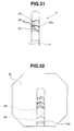
- another possible configuration may include a presetting member and a presetting portion shown in Figs. 21 and 22 or a presetting portion shown in Figs. 23 and 24 .
- a fit-in portion 42 that is a recess portion with a plane 42a and a tapered surface 42b is formed in, for example, a middle portion 41 of a treatment instrument insertion portion 11B of the treatment instrument 2.
- a presetting member 43 is provided, for example, at a predetermined position in the vicinity of the treatment instrument channel provided in the endoscope.
- the presetting member 43 includes an abutting surface 43a located in abutment with the plane 42a of the fit-in portion 42, and a slope 43b abutting the tapered surface 42b.
- the presetting member 43 is, for example, slidable in a direction of an arrow shown in Fig. 21 by means of an actuator (not shown in the drawings).
- the major axis of the treatment instrument insertion portion 11B is placed at a preset position with respect to a longitudinal direction of a treatment instrument channel 33B. Furthermore, when the presetting member 43 is placed in the fit-in portion 42 so that the slope 43b abuts against the tapered surface 42b, the amount of projection of the treatment instrument insertion portion 11B from, for example, the endoscope is set to a preset value.
- the treatment instrument insertion portion 11 is drawn out of the endoscope in a preset posture.
- the presetting member 43 not placed in the fit-in portion 42, the treatment instrument insertion portion 11 B is prevented from being drawn out of the endoscope in the preset posture.
- the operator or the staff member performs a readjustment operation such that the treatment instrument insertion portion 11B is drawn out of the endoscope in the preset posture.
- a recess portion 44 shaped substantially like a rectangular parallelepiped is formed in a predetermined site of a side peripheral surface of, for example, the tend-to-curve portion 14a of a treatment instrument insertion portion 11C of the treatment instrument 2.
- the recess portion 44 includes a pair of slopes 45 at side portions thereof.
- the recess portion 44 includes a longer portion 45a located on a distal end side thereof and a projecting portion 45b located on a proximal end side thereof and forming an abutting surface.
- a width dimension of the projecting portion 45b is set such that a protruding portion 46 described below can be fitted in the projecting portion 45b.
- the protruding portion 46 shown in Fig. 24 is placed in the recess portion 44.
- the protruding portion 46 is configured to project and retract freely through a hole 48 by means of a spring 47 that is a biasing member.
- the protruding portion 46 is provided to lie on a proximal end side of the curving portion 33c of the treatment instrument channel 33B of an endoscope 3B.
- the operator or the staff member operationally pushes in the treatment instrument insertion portion 11C by applying an amount of push-in force sufficient to resist the biasing force of the spring 47, to the treatment instrument insertion portion 11C.
- the protruding portion 46 is then pushed down to move the treatment instrument insertion portion 11C forward.
- the distal bending portion 13 of the treatment instrument insertion portion 11C passes through the curving portion 33c, the distal end portion of the treatment instrument insertion portion 11C is displayed on the screen.
- the operator or the staff member thereafter continues the push-in operation.
- the protruding portion 46 is placed in the recess portion 44 to reduce an insertion force amount.
- the operator or the staff member can determine that the treatment instrument insertion portion 11C has been inserted through the treatment instrument channel 33B in the preset state.
- the operator or the staff member determines that the treatment instrument insertion portion 11 has not been drawn out of the endoscope in the preset state, and performs the reinsertion operation.
- the protruding portion 46 With the protruding portion 46 placed in the recess portion 44, the protruding portion 46 abuts against the slope 45 to correct the misalignment of the treatment instrument insertion portion 11C with respect to the treatment instrument channel 33B in the major axis direction. Then, the protruding portion 46 is placed in the projecting portion 45b in abutment therewith. The operation of inserting the treatment instrument insertion portion 11C is thus completed.
- the treatment instrument insertion portion 11C is drawn out through the opening 34a in the endoscope 3B in a preset posture because the rotating direction of the treatment instrument insertion portion 11C around the major axis and the projection amount thereof are preset.
- the protruding portion 46 abuts against the slope 45 to slightly increase the insertion force amount. At this time, the operator or the staff member determines that the slight increase in insertion force amount is due to an increase in resistance resulting from the abutment of the protruding portion 46 against the slope 45. The operator or the staff member thus continues inserting the treatment instrument insertion portion into the treatment instrument channel.
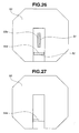
- an around-the-major-axis determination frame 51 and a projection amount determination frame 52 which are preset state determination frames are displayed on a screen 50 on which endoscopic images are displayed.
- reference numeral 53a denotes a first marking image.
- the first marking image 53a is a display image of an around-the-major-axis determination marking provided on the distal bending portion 13 of the treatment instrument insertion portion 11.
- Reference numeral 54a denotes a second marking image.
- the second marking image 54a is a display image of a projection amount determination marking provided on the distal bending portion 13 of the treatment instrument insertion portion 11.
- the projection amount determination marking is a peripheral marking formed around the major axis and having a predetermined width dimension.
- the treatment instrument insertion portion 11 is drawn out of the endoscope in the preset posture, then as shown in Fig. 26 , the first marking image 53a is placed in the around-the-major-axis determination frame 51. Furthermore, the second marking image 54a is placed in the projection amount determination frame 52.
- the treatment instrument insertion portion 11 is drawn out of the endoscope in the preset posture.
- the operator or the staff member can determine that the treatment instrument insertion portion 11 is not in the preset posture.
- the operator or the staff member draws the treatment instrument insertion portion 11 out of the endoscope in the preset posture by performing an adjustment operation, for example, an operation of moving forward or backward or rotating the treatment instrument insertion portion 11. If the projection amount need not be preset, the operator or the staff member determines, visually or using a sensor, whether or not the second joint in the treatment instrument insertion portion projects further than the joint in the raising table.
- Fig. 27 shows a method of making the determination on the basis of the endoscopic image displayed on the screen 50 of the display device.
- the operator or the staff member checks the screen for a marking image 54a of the projection amount determination marking to determine whether or not the joint 16 in the treatment instrument insertion portion 11 projects further than the joint 40 in the raising table 35.
- the projection amount determination marking is provided behind and at a predetermined distance from the distal bending portion 13 of the treatment instrument insertion portion 11.
- Fig. 28 shows an example of a configuration in which a sensor 55 is provided in the distal end portion 24.
- the sensor 55 is, for example, a magnetic sensor that detects, for example, a plurality of peripheral magnetic bodies 56 arranged around the major axis and behind the distal bending portion 13 of the treatment instrument insertion portion 11.
- the control portion 6a allows letters or the like indicating that the joints 15 and 16 in the treatment instrument insertion portion 11 project further than the joint 40 in the raising table 35, to be displayed in the screen (not shown in the drawings).
- the operator or the staff member can control the operation of the joints 15, 16, and 40 to perform an operation of moving the distal end of the treatment instrument insertion portion.
- a medical apparatus 1 A shown in Fig. 29 includes an integrated medical device 8A.
- the integrated medical device 8A includes an inputting device 7B instead of the inputting device 7 that is the joy stick.
- the inputting device 7B includes an inputting portion 7c via which a target distal end position (X, Y, Z) and a target distal end posture (Roll, Pitch, Yaw) of the distal end 11a of the treatment instrument insertion portion 11 of the treatment instrument 2 are inputted.
- target distal end position (X, Y, Z) and the target distal end posture (Roll, Pitch, Yaw) are set via the inputting portion 7c, three values in each of the target distal end position (X, Y, Z) and the target distal end posture (Roll, Pitch, Yaw) are used as target values.
- the control portion 6a of the integrated controller 6 calculates target angles for the joint 40 in the raising table 35 and the joints 15 and 16 in the treatment instrument 2 which joints are in a preset positional and postural relationship with respect to the inputted target values as shown in Fig. 11 .
- the control portion 6a controls the joints 15, 16, and 40.
- the integrated medical device is composed of the integrated controller and the inputting device including the inputting portion via which the target distal end position and posture are inputted. Consequently, the operator can move the distal end of the treatment instrument insertion portion to any three-dimensional position within a movable range.
- the operator or the staff member can select a treatment instrument having a desired degree of freedom.
- the operator can electrically drive the raising table of the endoscope and the bending portion of the treatment instrument by means of simpler operations to achieve wide ranges of the target distal end positions and postures.
- a medical apparatus 1B in Fig. 30 includes an integrated medical device 8B.
- the integrated medical device 8B includes an integrated controller 6A and an inputting device 7.
- the integrated controller 6A includes an image data acquiring portion 6b that is determination means, a measurement instruction switch 6c, and a control portion 6d.
- the image data acquiring portion 6b acquires image data of an endoscopic image generated by an image processing circuit provided in the camera control unit.
- the control portion 6d of the integrated medical device 8B reads the marks provided on the distal bending portion 13 of the treatment instrument 2, from the image data acquired by the image data acquiring portion 6b.
- the control portion 6d thus acquires the postural and positional relationships of the treatment instrument insertion portion 11 drawn out of the endoscope 3.
- a projection amount acquisition mark 61 and a plurality of rotation amount acquisition marks 62 are provided at predetermined positions on the central bending piece 13m, which forms the treatment instrument 2.
- the projection amount acquisition mark 61 is determination means for allowing the projection amount to be acquired.
- the plurality of rotation amount acquisition marks 62 are determination means for allowing the rotation amount in the major axis direction to be acquired.
- the projection amount acquisition mark 61 is a peripheral line drawn in the center of the central bending piece 13m around the major axis.
- the projection amount acquisition mark is hereinafter referred to as the peripheral line 61.
- the rotation amount acquisition marks 62 are a plurality of orthogonal lines that are orthogonal to the peripheral line 61 and parallel to the major axis.
- the rotation amount acquisition marks are hereinafter referred to as the orthogonal lines 62.
- a longer one of the plurality of orthogonal lines 62 is a reference line 63 showing the preset position.
- a color of the peripheral line 61 may be different from that of the orthogonal lines 62.
- Other configuration is similar to that in the first embodiment.
- the same members are denoted by the same reference numerals, and the description thereof is omitted.
- the staff member constructs the medical apparatus 1B shown in Fig. 30 .
- the operator observing an endoscopic image displayed on the screen of the display device (not shown in the drawings), the operator appropriately performs the operation of bending the bending portion 25 using the bending knobs 27 and 28, the operation of twisting the insertion portion 21, and the like. The operator thus draws out the distal end portion 24 to the vicinity of the opening in the papilla.
- the operator instructs the staff member to use the treatment instrument 2.
- the staff member inserts the treatment instrument insertion portion 11 of the treatment instrument 2 into the treatment instrument channel 33.
- the staff member then pushes in the treatment instrument insertion portion 11 to insert the treatment instrument insertion portion 11 through the channel tube 33d with the proximal end in communication with the treatment instrument insertion port 32.
- the staff member thereafter determines whether or not the projection amount detection mark 19 has reached the vicinity of the opening end of treatment instrument insertion port 32.
- the treatment instrument insertion portion 11 is drawn out through the opening 34a in the endoscope 3. Then, as shown in Fig. 32 , the distal end 11a of the treatment instrument insertion portion 11 and a part of the distal bending portion 13 are displayed on a screen 60 of the display device.
- the operator determines whether or not the second joint 16 projects further than the raising joint 40, for example, on the basis of the marking image 54a of the projection amount determination marking in the endoscopic image.
- Reference numeral 65 denotes a projection amount reference line (hereinafter referred to as a first reference line).
- Reference numeral 66 denotes a major-axis-direction rotation amount reference line (hereinafter referred to as a second reference line).
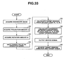
- step S1 in Fig. 33 the control portion 6d acquires an endoscopic image.
- the control portion 6d subsequently shifts to step S2 to acquire a projection amount L5 by which the joint 16 projects further than the joint 40, on the basis of a distance between the peripheral line 61 provided on the treatment instrument 2 and the first reference line 65 displayed on the endoscopic image from the endoscopic image.
- step S3 the control portion 6d further acquires a rotation amount ⁇ 4 in the major axis direction with respect to the preset state on the basis of a distance between the second reference line 66 displayed on the endoscopic image and the orthogonal line 62.
- control portion 6d acquires data on the posture and position of the treatment instrument insertion portion 11 drawn out into the body through the opening 34a in the endoscope 3. During the data acquisition, the joints 15, 16, and 40 in the treatment instrument insertion portion 11 are not rotated.
- step S4 the operator operationally tilts the operation lever 7a to input the target values.
- the control portion 6d then shifts to step S5 to calculate target bending angles for the joints 15, 16, and 40 on the basis of the posture data acquired in steps S2 and S3 and the target values inputted via the operation lever 7a.
- step S6 the control portion calculates a difference between a current angle of each of the joints 15, 16, and 40 and the corresponding target bending angle calculated in step S5.
- step S7 the control portion shifts to step S7.
- step S7 the control portion 6d outputs driving control signals allowing the driving motor 38 and the driving actuators 17 and 18 to be driven.
- step S8 the raising table 35 and the distal bending portion 13 of the treatment instrument insertion portion 11 are driven to achieve target bending directions and the target angles. The driving is then stopped.
- the rotation angles ⁇ 2 and ⁇ 3 of the joints 16 and 40 are determined with a rotation amount ⁇ 4 taken into account.
- ⁇ 1max denotes the maximum bending angle of the raising joint 40.
- ⁇ 2max denotes the maximum bending angle of the joint 16.
- ⁇ 3max denotes the maximum bending angle of the joint 15.
- a variation in projection amount L5 that is, a variation in length, may be used as a parameter for distributing the input of the operation lever 7a between the raising table 35 and the distal bending portion 13 of the treatment instrument 2 in the ratio of r1 to r2.
- the integrated controller includes the image data acquiring portion that acquires image data generated by the image processing circuit. Furthermore, the integrated controller includes the control portion which acquires the posture data on the treatment instrument insertion portion from the image data and which generates the driving control signals allowing the driving motor and the driving actuators to be driven on the basis of the posture data and the current rotation angle and the target values of each of the joints.
- the target bending directions and target angles corresponding to the target values can be achieved by operationally tilting the operation lever to input the target values without the need to provide the presetting means composed of the tend-to-curve portion of the treatment instrument insertion portion of the treatment instrument and the curving portion of the treatment instrument channel of the endoscope.
- the correct posture and position data can be acquired only when the joints 15, 16, and 40 are in the preset state, that is, at 0°.
- the rotation amount ⁇ 4 and the projection amount L5 can always be measured, for example, by providing a rotation sensor directly acquiring the rotation amount ⁇ 4 on the basis of a pattern of energization or a variation in resistance value or a linear sensor directly acquiring the projection amount L5 on the basis of a difference in resistance value, the number of times that light has been turned on and off, or the number of times that energization has been turned on and off.
- an inputting device 7B with the inputting portion 7c may be provided to allow the target distal end position (X, Y, Z) and the target distal end posture (Roll, Pitch, Yaw) to be set so that the target angles for the joints 15, 16, and 40 can be calculated on the basis of inverse kinematics to allow the joints 15, 16, and 40 to be controlled.
Landscapes
- Health & Medical Sciences (AREA)
- Life Sciences & Earth Sciences (AREA)
- Surgery (AREA)
- Biomedical Technology (AREA)
- Medical Informatics (AREA)
- Optics & Photonics (AREA)
- Pathology (AREA)
- Radiology & Medical Imaging (AREA)
- Biophysics (AREA)
- Engineering & Computer Science (AREA)
- Physics & Mathematics (AREA)
- Heart & Thoracic Surgery (AREA)
- Nuclear Medicine, Radiotherapy & Molecular Imaging (AREA)
- Molecular Biology (AREA)
- Animal Behavior & Ethology (AREA)
- General Health & Medical Sciences (AREA)
- Public Health (AREA)
- Veterinary Medicine (AREA)
- Gastroenterology & Hepatology (AREA)
- Endoscopes (AREA)
- Instruments For Viewing The Inside Of Hollow Bodies (AREA)
- Surgical Instruments (AREA)
Abstract
Description
- The present invention relates to a medical apparatus including a first medical device with a bending portion which is provided in an insertion portion and which is bent by a driving force of a driving portion, and a second medical device with an external force applying portion that applies an external force to the insertion portion of the first medical device by means of the driving force of the driving portion so that the insertion portion can operate.
- In recent years, what is called endoscopic retrograde cholangio pancreatography (hereinafter referred to as ERCP) has been performed in which a diseased site of a canalicus, for example, a diseased site in a pancreaticobiliary system, is examined and treated using a sideward viewing endoscope with an image pickup optical system disposed on a side surface of a distal end of an insertion portion. The ERCP using the sideward viewing endoscope includes examinations in which images of a bile duct or a pancreatic duct are picked up using the endoscope, and therapeutic treatments in which gallstone present in a common bile duct or the like is recovered using a balloon or a treatment instrument.
- Since the pancreatic duct and the bile duct are very thin, it is difficult to insert, for the ERCP, the distal end portion of the insertion portion of the endoscope directly into the bile duct or the pancreatic duct. Normally, an operator first inserts the distal end portion of the insertion portion of the sideward viewing endoscope until the distal end portion reaches the vicinity of a duodenal papilla. Thereafter, while observing appropriate sites through the endoscope, the operator draws out any of various endoscopic treatment instruments (hereinafter simply referred to as "treatment instruments") such as a cannulation tube through a treatment instrument insertion tube cavity formed in the side surface of the distal end portion of the insertion portion. The operator then inserts the treatment instrument into the bile duct or the pancreatic duct.
- At this time, the operator uses what is called a treatment instrument raising table provided in the vicinity of the opening at the distal end of the treatment instrument insertion tube cavity. A raising angle of the treatment instrument raising table can be varied by a manual operation. Thus, varying the raising angle of the treatment instrument raising table allows a direction in which the treatment instrument is drawn out through the opening to be varied to easily guide the treatment instrument to the bile duct or the pancreatic duct.
- For example, an
endoscopic device 150 shown inFig. 1 includes asideward viewing endoscope 100 and anendoscopic treatment instrument 110. An opening 102a is formed at adistal end portion 102 of aninsertion portion 101 of thesideward viewing endoscope 100. Aninsertion portion 111 of theendoscopic treatment instrument 110, for example, an imaging tube, a high-frequency treatment instrument, or a balloon catheter (hereinafter referred to as the treatment instrument insertion portion in order to distinguish this insertion portion from theinsertion portion 101 of the sideward viewing endoscope 100) is drawn out through the opening 102a. - To draw out the treatment
instrument insertion portion 111 through the opening 102a and then insert the treatmentinstrument insertion portion 111 through the bile duct, the operator performs a procedure described below. - First, the operator performs a manual operation of operating a
bending knob 104 provided on anoperation portion 103 to bend a bending portion (not shown in the drawings), a manual operation of twisting theinsertion portion 101, and the like. Thus, thedistal end portion 102 is placed opposite a target site, for example, aduodenal papilla 120 in a desired condition. - Then, the operator draws out the treatment
instrument insertion portion 111 into a body via a treatment instrument insertion channel (not shown in the drawings) formed in theinsertion portion 101 of thesideward viewing endoscope 100 and via a treatment instrument raising table (hereinafter simply referred to as a raising table) 105 located in the vicinity of the opening 102a. Since the raising table 105 has not been raised yet, the treatmentinstrument insertion portion 111 is thus drawn out as shown by a dashed line or an alternate long and short dash line. - The amount by which the treatment
instrument insertion portion 111 is drawn out varies, for example, as shown by the dashed line and the alternate long and short dash line depending on the amount by which the treatmentinstrument insertion portion 111, positioned close to the operator's hands, is pushed in. - After drawing the treatment
instrument insertion portion 111 into the body, the operator operates a raisingtable operation lever 106. Then, a raising wire (not shown in the drawings) inserted through theinsertion portion 101 is pulled. An angle of the treatment instrument raising table 105 is varied in conjunction with this traction. That is, a direction in which the treatmentinstrument insertion portion 111 is drawn out is changed, for example, from one shown by the alternate long and short dash line to one shown by a solid line. Thus, adistal end 112 of the treatmentinstrument insertion portion 111 is placed opposite theduodenal papilla 120. - However, in this state, the direction in which the treatment
instrument insertion portion 111 is drawn out is toward apancreatic duct 121. Introducing the treatmentinstrument insertion portion 111 into abile duct 122 is thus difficult. Consequently, the operator makes adjustment such as an operation of thebending knob 104, provided on theoperation portion 103, to introduce the treatmentinstrument insertion portion 111 into thebile duct 122. - Thus, the operator needs to be skilled in order to perform the manual operation of placing the
distal end portion 102 of theinsertion portion 101 of theendoscope 100 opposite theduodenal papilla 120 and smoothly introducing the treatmentinstrument insertion portion 111 into thepancreatic duct 121 or thebile duct 122. - In recent years, a sideward viewing endoscope with an electric raising table has been proposed in order to improve the operator's workability. This sideward viewing endoscope is configured such that the raising wire is pulled by, for example, a driving motor provided in the operation portion. Furthermore, Japanese Patent Application Laid-Open Publication No.
7-000350 - Also for the treatment instrument, a treatment instrument manipulator has recently been proposed in which the treatment instrument insertion portion includes a bending portion having a plurality of active joints in order to improve the operator's operability. For example, Japanese Patent Application Laid-Open Publication No.
8-224241 - As shown in
Fig. 2 , asideward viewing endoscope 130 with an electric treatment instrument raising table and amedical manipulator 140 form anendoscopic device 150A. The operator's workability can be drastically improved. - In
Fig. 2 ,reference numeral 131 denotes a raising table angle instruction inputting portion. The operator tilts the raising table angleinstruction inputting portion 131, for example, in the direction of arrow a. Adriving motor 107 in theoperation portion 103 is then driven to pull the raising wire (not shown in the drawings) inserted through theinsertion portion 101. Then, the raising table 132 is raised. On the other hand,reference numeral 141 denotes a joy stick for a bending operation provided in a treatmentinstrument operation portion 142. Thejoy stick 141 can be operationally tilted, for example, in the direction of arrow c, d, e, or f. In response to the tilting operation of thejoy stick 141, drivingactuators 143 and 144 in the treatmentinstrument operation portion 142 are driven. Then, thebending potion 113 is bent, for example, as shown by an alternate one and two short dash line to enable a position of thedistal end 112 to be changed. - However, with the
endoscopic device 150A configured as shown inFig. 2 , when thedistal end 112 of the treatmentinstrument insertion portion 111 is placed opposite the target site, the raising table angleinstruction inputting portion 131 and thejoy stick 141 need to be operated. It is cumbersome for the operator alone to operate the raising table angleinstruction inputting portion 131 and thejoy stick 141. On the other hand, if the operator operates one of the raising table angleinstruction inputting portion 131 and thejoy stick 141 and an assistant operates the other, associating the two operations with each other is difficult. - An object of the present invention is to provide a medical apparatus with high operability which can easily approach the target site without the need to operate the respective operation portions provided in a plurality of electrically operative medical devices.
- A medical apparatus comprises a first medical device, a second medical device, an integrated inputting device, and an integrated control device. The medical device comprises an insertion portion comprising a bending portion that is bent by a driving force of a first driving portion and a first control device drivingly controlling the first driving portion. The second medical device comprises an external force applying portion applying an external force to the insertion portion of the first medical device to move the insertion portion, a second driving portion generating a driving force allowing the external force applying portion to be operated, and a second control device drivingly controlling the second driving portion. The integrated inputting portion instructs a distal end of the insertion portion to be moved to a target position or a target posture or in a target direction, in a configuration in which the external force of the external force applying portion provided in the second medical device can be applied to the insertion portion of the first medical device. The integrated control device drivingly controls at least one of the first driving portion provided in the first medical device and the second driving portion provided in the second medical device on the basis of an instruction from the integrated inputting device.
- The above and other objects, features and advantages of the invention will become more clearly understood from the following description referring to the accompanying drawings.
-
-
Fig. 1 is a diagram illustrating an endoscopic device including a sideward viewing endoscope and an endoscope treatment instrument; -
Fig. 2 is a diagram illustrating an endoscopic device including a sideward viewing endoscope with an electric treatment instrument raising table, and a medical manipulator; -
Figs. 3 to 28 are diagrams illustrating a first embodiment of a medical apparatus, andFig. 3 is a diagram illustrating the configuration of the medical apparatus; -
Fig. 4 is a diagram illustrating the configuration of the treatment instrument insertion portion of the medical manipulator; -
Fig. 5 is a diagram illustrating the configuration of the treatment instrument insertion portion of the medical manipulator; -
Fig. 6 is a diagram illustrating a distal end portion of the sideward viewing endoscope; -
Fig. 7 is a diagram illustrating a treatment instrument channel with a tend-to-curve portion provided in the insertion portion of the sideward viewing endoscope, and the treatment instrument raising table; -
Fig. 8 is a diagram illustrating a relationship among joints observed when the treatment instrument insertion portion of the medical manipulator is placed in the treatment instrument channel in a preset posture; -
Fig. 9 is a diagram illustrating a state the medical manipulator is inserted through the treatment instrument channel, wherein the tend-to-curve portion of the medical manipulator substantially fits a curving portion of the treatment instrument channel; -
Fig. 10 is a diagram illustrating a state where the medical manipulator is inserted through the treatment instrument channel, wherein the tend-to-curve portion of the medical manipulator is displaced from the curving portion of the treatment instrument channel in a major axis direction; -
Fig. 11 is a diagram illustrating a state where the treatment instrument insertion portion of the medical manipulator is placed in a preset posture; -
Figs. 12 and 13 are diagrams illustrating a first example of control performed by a control portion; -
Fig. 12 is a diagram showing a tilting operation state of an operation lever; -
Fig. 13 is a diagram illustrating a tilting operation of the operation lever and an operating state of the joints; -
Figs. 14 and 15 are diagrams illustrating a second example of control performed by the control portion; -
Fig. 14 is a diagram showing a tilting operation state of the operation lever; -
Fig. 15 is a diagram illustrating a tilting operation of the operation lever and an operating state of the joints; -
Figs. 16 to 19 are diagrams illustrating a third example of control performed by the control portion; -
Fig. 16 is a diagram illustrating a state where the operation lever is operationally tilted by an angle γ1; -
Fig. 17 is a diagram illustrating an operating state of the joints when the operation lever is operationally tilted by the angle γ1; -
Fig. 18 is a diagram illustrating a state where the operation lever is operationally tilted by an angle γ2 exceeding a rotation angle θ1max; -
Fig. 19 is a diagram illustrating an operational state of respective joints in a state where the operation lever is operationally tilted by the angle γ2 exceeding the rotation angle θ1 max; -
Fig. 20 is a diagram illustrating a relationship between a forward viewing endoscope with a raising table and a treatment instrument with a distal bending portion; -
Figs. 21 and22 are diagrams illustrating another example of the configuration of presetting means; -
Fig. 21 is a diagram illustrating a presetting portion and a presetting member which preset a rotation amount around a major axis and a projection amount; -
Fig. 22 is a diagram illustrating a state preset by the presetting portion and the presetting member; -
Figs. 23 and24 are diagrams illustrating another example of the configuration of the presetting means; -
Fig. 23 is a diagram illustrating the presetting portion presetting the rotation amount around the major axis and projection amount; -
Fig. 24 is a diagram illustrating the presetting member and a preset state in which the presetting member is located in the presetting portion; -
Figs. 25 and26 are diagrams illustrating yet another example of the configuration of the presetting means; -
Fig. 25 is a diagram illustrating an endoscopic image displayed on a screen and a preset state determination frame; -
Fig. 26 is a diagram illustrating a relationship between the determination frame and a marking image observed when the treatment instrument insertion portion drawn out of the endoscope is in a preset posture; -
Fig. 27 is a diagram illustrating a method of determining whether or not a joint in the distal bending portion projects from a raising joint, on the basis of the endoscopic image displayed on the screen of a display device; -
Fig. 28 is a diagram illustrating an example of the configuration of a medical apparatus including a sensor detecting whether or not the joint in the distal bending portion projects from the raising joint; -
Fig. 29 is a diagram illustrating a variation of the medical apparatus; -
Figs. 30 to 33 are diagrams relating to a second embodiment of the medical apparatus; -
Fig. 30 is a diagram illustrating another configuration of the medical apparatus; -
Fig. 31 is a diagram illustrating a projection amount acquisition mark and a rotation amount acquisition mark provided on a central bending piece; -
Fig. 32 is a diagram illustrating the projection amount acquisition mark and rotation amount acquisition mark on the treatment instrument insertion portion as well as a projection amount reference line and a major-axis-direction rotation amount reference line, the marks and reference lines being displayed on the screen; and -
Fig. 33 is a flowchart illustrating an example of control performed by the control portion. - Embodiments of the present invention will be described with reference to the drawings.
- A first embodiment of a medical apparatus will be described with reference to
Figs. 3 to 28 . - The medical apparatus will be described with reference to
Figs. 3 to 11 . - As shown in
Fig. 3 , amedical apparatus 1 according to the present embodiment is composed of a medical manipulator (hereinafter simply referred to as a treatment instrument) 2 that is an active treatment instrument, a sideward viewing endoscope (hereinafter simply referred to as an endoscope) 3 with an active raising table (seereference numeral 35 inFigs. 6 and7 ; hereinafter simply referred to as a raising table), and atreatment instrument controller 4, a raisingtable controller 5 and anintegrated controller 6, and an integrated inputting device (hereinafter simply referred to as an inputting device) 7; the controllers and the inputting device are peripheral devices. Theinputting device 7 includes, for example, an operationallytiltable operation lever 7a. - The
inputting device 7 is, for example, a joy stick and is operationally tiltable in any direction using a base portion of anoperation lever 7a as a support point. Specifically, theoperation lever 7a is operationally tiltable in the direction of arrow F that is a Ya axis direction in an Oa coordinate system shown in the figures, the direction of arrow B that is a -Ya axis direction, the direction of arrow L that is a Za axis direction, and the direction of arrow R that is a -Za axis direction. - The
treatment instrument 2 is a first medical device and includes a treatmentinstrument insertion portion 11 and abending driving portion 12. Thebending driving portion 12 contains drivingactuators treatment instrument 2 is an imaging tube, a high-frequency treatment instrument, a balloon catheter, and the like. - As shown in
Fig. 4 , the treatmentinstrument insertion portion 11 includes adistal bending portion 13 and aflexible tube portion 14. Theflexible tube portion 14 has a tend-to-curve portion 14a that is presetting means. The tend-to-curve portion 14a is configured to bend at a predetermined radius in a predetermined direction. The tend-to-curve portion 14a of theflexible tube portion 14 is positioned on a proximal end side of thedistal bending portion 13. In the present embodiment, the bending shape of the tend-to-curve portion 14a substantially matches a direction in which a first joint 15 described below rotates. - The
distal bending portion 13 forms a distal end side of the treatmentinstrument insertion portion 11. Thedistal bending portion 13 includes, for example, adistal bending piece 13f, acentral bending piece 13m, aproximal bending piece 13r. Thedistal bending piece 13f and thecentral bending piece 13m are coupled together by the first joint 15 so as to be pivotally movable. Thecentral bending piece 13m and theproximal bending piece 13r are coupled together by a second joint 16 so as to be pivotally movable. - The first joint 15 is pivotally movable with respect to a Zb axis orthogonal to an Xb axis in an Ob coordinate system in the figures. The second joint 16 is pivotally movable with respect to a Yb axis in the Ob coordinate system. The Xb axis in the Ob coordinate system is parallel to a major axis shown by a dashed line.
- That is, the
distal bending piece 13f, coupled to thecentral bending piece 13m by the first joint 15, is configured to rotate through an angle Yθb in the Yb axis direction and through an angle -Yθb in the -Yb axis direction, with respect to the Xb axis as shown inFig. 5 . A first end and a second end of a distal bending piece wire 13fw are fixed to predetermined positions of thedistal bending piece 13f. - A central portion of the distal bending piece wire 13fw is fixedly disposed on a pulley (not shown in the drawings) provided in a
bending driving portion 12. The pulley is pivotally moved by afirst driving actuator 17, provided in thebending driving portion 12. When thefirst driving actuator 17 is driven to rotate the pulley, for example, clockwise, a first end of the distal bending piece wire 13fw is pulled, a second end is loosened. Thus, thedistal bending piece 13f rotates through, for example, the angle Yθb. In contrast, when thefirst driving actuator 17 is driven to rotate the pulley counterclockwise, the second end of the distal bending piece wire 13fw is pulled, while the first end is loosened. Thus, thedistal bending piece 13f rotates through an angle -Yθb. - On the other hand, the
central bending piece 13m, coupled to theproximal bending piece 13r by the second joint 16, is configured to rotate through an angle Zθb in the Zb axis direction and through an angle -Zθb in the -Zb axis direction, with respect to the Xb axis direction. A first end and a second end of a central bending piece wire 13mw are fixed to predetermined positions of thecentral bending piece 13m. - In
Fig. 5 , the Zb axis direction is a direction away from the reader, and the - Zb axis direction is a direction toward the reader. -
Reference numeral 19 shown inFigs. 4 and5 denotes a projection amount detection mark (hereinafter simply referred to as a mark). Themark 19 is presetting means and is composed of, for example, a band-like peripheral line. Alignment of themark 19 with an opening end in a treatmentinstrument insertion port 32 described below indicates that thedistal end 11a of the treatmentinstrument insertion portion 11 is drawn out, by a predetermined amount, from anopening 34a in a raising table arrangement space (reference numeral 34 inFig. 6 ; hereinafter simply referred to as a table space) provided in adistal end portion 24, described below, of theendoscope 3. - A central portion of the central bending piece wire 13mw is fixedly disposed on the pulley (not shown in the drawings) provided in the
bending driving portion 12. The pulley is pivotally moved by asecond driving actuator 18, provided in thebending driving portion 12. When thesecond driving actuator 18 is driven to rotate the pulley, for example, clockwise, a first end of the central bending piece wire 13mw is pulled, a second end is loosened. Thus, thecentral bending piece 13m rotates through, for example, the angle Zθb. In contrast, when thesecond driving actuator 18 is driven to rotate the pulley counterclockwise, the second end of the central bending piece wire 13mw is pulled, while the first end is loosened. Thus, thecentral bending piece 13m rotates through an angle -Zθb. - A distance from a distal end surface of the treatment
instrument insertion portion 11 to the first joint 15 is preset to L1. A distance from the first joint 15 to the second joint 16 is preset to L2. In theactual treatment instrument 2, the bendingpieces - The
endoscope 3 shown inFig. 3 includes aninsertion portion 21, anoperation portion 22, and auniversal cord 23. Theinsertion portion 21 is inserted into a body. Theoperation portion 22 is provided at a proximal end side of theinsertion portion 21. Theuniversal cord 23 extends from theoperation portion 22. Theuniversal cord 23 includes an endoscope connector (not shown in the drawings) at a proximal end portion thereof. - The endoscope connector is connected to a light source device that supplies illumination light, for example, via an illumination window described below. An image cable extending from the endoscope connector is connected to a camera control unit (not shown in the drawings). The camera control unit includes an image processing circuit that generates a video signal from an image signal resulting from photoelectric conversion by an image pickup device (not shown in the drawings) provided in the distal end portion of the
endoscope 3. The video signal generated by the camera control unit is outputted to the display device. When the video signal is outputted to the display device, an endoscopic image is displayed on the screen of the display device. - The
insertion portion 21 is composed of a rigiddistal end portion 24, a bendingportion 25 that is, for example, bendable upward, downward, rightward, and leftward, and an elongateflexible tube portion 26; thedistal end portion 24, the bendingportion 25, and theflexible tube portion 26 are connected together in this order from the distal end side. - The
operation portion 22 also serves as a gripping portion. Theoperation portion 22 has avertical bending knob 27 that bends the bendingportion 25 in a vertical direction, alateral bending knob 28 that bends the bending portion in a lateral direction, an air orwater supply button 29, asuction button 30, a plurality ofremote buttons 31, and the like. Theremote buttons 31 give instructions on, for example, driving control of an image pickup unit or the like (not shown in the drawings) provided in thedistal end portion 24.Reference numeral 31 a denotes a raising table angle instruction inputting portion that is a second inputting portion. - The
operation portion 22 has a treatmentinstrument insertion port 32 forming a proximal end portion of the treatment instrument channel described below (seereference numeral 33 inFig. 7 ). Thetreatment instrument 2 is adapted to be drawn out through theopening 34a in thedistal end portion 24 via the treatmentinstrument insertion port 32, thetreatment instrument channel 33, and the raising table 35. -
Reference numeral 38 denotes a driving motor. The drivingmotor 38 is a second driving portion and moves the raising wire (not shown in the drawings) forward and backward, which operationally raises the raising table 35.Reference numeral 39 denotes an electric connection port. Aconnector 9c provided on asecond connection cord 9b is removably connected to theconnection port 39. Connecting theconnector 9c to theconnection port 39 allows theendoscope 3 to be electrically connected to the raisingtable controller 5. In the present embodiment, theendoscope 3 is a second medical device. - As shown in
Figs. 6 and7 , thedistal end portion 24 includes the raising table 35, anobservation window 36 forming an observing optical system, and anillumination window 37 forming an illuminating optical system. The raising table 35 is an external force applying portion and is pivotally movably located in thetable space 34, formed in thedistal end portion 24. Thedistal opening 33a in thetreatment instrument channel 33 communicates with thetable space 34. - The raising table 35 has an initial position in which a
bottom side surface 35b of the raising table 35 abuts against abottom surface 34b of thetable space 34. The raising table 35 is configured to be pivotally movable with respect to thedistal end portion 24 by a raising joint 40. An end portion of the raising wire (not shown in the drawings) is fixed to a predetermined position of the raising table 35. - The raising table 35 is pivotally movable with respect to a Zc axis that is orthogonal to an Xc axis of the Oc coordinate system. The raising table 35 is configured to rotate through an angle Yθc in a Yc axis direction with respect to the Xc axis. The Xc axis in the Oc coordinate system is parallel to a treatment instrument guiding direction in which the
treatment instrument 2 is drawn out when the raising table 35 is located in the initial position. - When the raising wire inserted through the
insertion portion 21 is pulled in the major axis direction by the drivingmotor 38, the raising angle of the raising table 35 is varied in increments of the angle Yθc, for example, as shown by a dashed line. In this state, when the raising wire that has been being pulled by the drivingmotor 38 is loosened, the raising table 35 moves gradually toward the initial position as the raising wire loosens. - As shown in
Fig. 7 , achannel hole 33b forming thetreatment instrument channel 33 is formed in thedistal end portion 24. Acap 33e is fixedly disposed on a proximal end side of thechannel hole 33b. A distal end portion of achannel tube 33d is fixedly disposed on thecap 33e. - A curving
portion 33c shaped to be bent at a predetermined radius is formed on thedistal opening 33a side of thechannel hole 33b. The curvingportion 33c is presetting means. A direction in which the curvingportion 33c is bent substantially matches a direction in which the raising joint 40 rotates. A bending shape of the curvingportion 33c substantially matches a bending shape of the tend-to-curve portion 14a of theflexible tube portion 14, forming the treatmentinstrument insertion portion 11. - Thus, when the treatment
instrument insertion portion 11 is inserted through thetreatment instrument channel 33 as shown inFig. 6 , themark 19 aligns with the opening end of the treatmentinstrument insertion port 32 to place the tend-to-curve portion 14a on the curvingportion 33c. Thus, the treatmentinstrument insertion portion 11 is drawn out of theopening 34a in theendoscope 3 at a preset posture. A distance between the raising joint 40 and the second joint 16 is preset to L3. - In the present embodiment, a rotating direction of the first joint 15 is preset to be the same as that of the raising joint 40. This is because the Ob coordinate system for the first joint 15 substantially matches the Oc coordinate system for the raising joint 40.
- In the present embodiment, the configuration in which the curving
potion 33c is formed in thechannel hole 33b is illustrated. However, in a configuration in which thechannel tube 33d extends to thedistal opening 33a, a tend-to-curve portion corresponding to the tend-to-curve portion 14a of theflexible tube portion 14 is provided on thedistal opening 33a side of thechannel tube 33d. - In the above description, the bending
portion 25 is bent in the vertical direction and the lateral direction. The upward direction corresponds to a Yo axis direction in an Oo coordinate system shown inFigs. 6 and7 . The downward direction corresponds to a -Yo axis direction that is opposite to the Yo axis direction. On the other hand, the rightward direction corresponds to a Zo axis direction in the Oo coordinate system. The leftward direction corresponds to a -Zo axis direction that is opposite to the Zo axis direction. InFig. 7 , the Zo axis direction is a direction away from the reader, and the -Zo axis direction is a direction toward the reader. - The
treatment instrument controller 4 shown inFig. 1 is a first control device. Thetreatment instrument controller 4 includes acontrol portion 4a. Thecontrol portion 4a controls driving of theactuators treatment instrument 2 to move thedistal end 11a in the vertical direction or the lateral direction. - The
treatment instrument controller 4 is electrically connected to thebending driving portion 12 via thefirst connection cord 9a. For example, theinputting device 7 can be connected to thetreatment instrument controller 4. By connecting theinputting device 7 to thetreatment instrument controller 4, and in this state, operationally tilting theoperation lever 7a of theinputting device 7, thedistal end 11a can be moved in the vertical direction, the lateral direction, or a synthesis direction of the vertical and lateral directions. - Specifically, for example, when the operator operationally tilts the
operation lever 7a of theinputting device 7 in the direction of arrow F, thefirst driving actuator 17, provided in thetreatment instrument 2, is driven. Then, thedistal bending piece 13f, located parallel to the Xb axis, rotates in the Yb axis direction in association with an angle through which theoperation lever 7a has been tilted. In contrast, when the operator operationally tilts theoperation lever 7a in the direction of arrow B, thefirst driving actuator 17 is driven to rotate thedistal bending piece 13f in the - Yb axis direction in association with the angle through which theoperation lever 7a has been tilted. - On the other hand, when the operator operationally tilts the
operation lever 7a in the direction of arrow R, thesecond driving actuator 18 is driven to rotate thecentral bending piece 13m located parallel to the Xb axis, in the Zb axis direction in association with the angle through which theoperation lever 7a has been tilted. In contrast, when the operator operationally tilts theoperation lever 7a in the direction of arrow L, thesecond driving actuator 18 is driven to rotate thecentral bending piece 13m in the -Zb axis direction in association with the angle through which theoperation lever 7a has been tilted. - The raising
table controller 5 is a second control device. The raisingtable controller 5 includes acontrol portion 5a. Thecontrol portion 5a controls driving of the drivingmotor 38, provided in theendoscope 3, to vary the raising angle of the raising table 35. - The raising
table controller 5 is electrically connected to the drivingmotor 38 in theoperation portion 22 via thesecond connection cord 9b. For example, theinputting device 7 can also be connected to the raisingtable controller 5. The raising table 35 can be operated by connecting theinputting device 7 to the raisingtable controller 5, and in this state, operationally tilting theoperation lever 7a of theinputting device 7 in the direction of arrow F or arrow B. - Specifically, for example, when the operator operationally tilts the
operation lever 7a of theinputting device 7 in the direction of arrow F, the drivingmotor 38, provided in theendoscope 3, is driven to pull the raising wire inserted through theinsertion portion 21. Then, the raising table 35 rotates in the Yc axis direction in association with the angle through which theoperation lever 7a has been tilted. In contrast, when the operator operationally tilts theoperation lever 7a of theinputting device 7 in the direction of arrow B, the drivingmotor 38 is driven in the opposite direction. At this time, with thebottom side surface 35b of the raising table 35 not abutting against thebottom surface 34b of thetable space 34, the raising table 35 rotates in the -Yc axis direction as the raising wire loosens. If thebottom side surface 35b of the raising table 35 abuts against thebottom surface 34b of thetable space 34 when the operator operationally tilts theoperation lever 7a in the direction of arrow B, the drivingmotor 38 remains stopped. - The
integrated controller 6 is an integrated control device. Theintegrated controller 6 includes acontrol portion 6a. Theintegrated controller 6 is combined with theinputting device 7 to constitute an integratedmedical device 8. That is, with thetreatment instrument controller 4 and the raisingtable controller 5 connected to the integratedmedical device 8, thecontrol portion 6a drivingly controls theactuators treatment instrument 2, and the drivingmotor 38 provided in theendoscope 3. - Specifically, when the operator operationally tilts the
operation lever 7a of theinputting device 7 in the direction of arrow F or arrow B, thecontrol portion 6a drives at least one of thefirst driving actuator 17 and the drivingmotor 38. On the other hand, when the operator operationally tilts theoperation lever 7a in the direction of arrow R or arrow L, thecontrol portion 6a drives thesecond driving actuator 18. - In the present embodiment, when the
inputting device 7, thetreatment instrument controller 4, and the raisingtable controller 5 are connected to theintegrated controller 6, the function of the raising table angleinstruction inputting portion 31a and the function of ajoy stick 12a are off; the raising table angleinstruction inputting portion 31a is provided in theendoscope 3, and thejoy stick 12a is shown by a dashed line and is a first inputting portion provided in thebending driving portion 12. - Furthermore, in the present embodiment, the
treatment instrument controller 4 and theintegrated controller 6 are connected together by afirst signal cable 9d. The raisingtable controller 5 and theintegrated controller 6 are connected together by asecond signal cable 9e. However, the connection between thetreatment instrument controller 4 and theintegrated controller 6 and the connection between the raisingtable controller 5 and theintegrated controller 6 may be established by one type of signal cable rather than by the separate signal cables. - The operation of the
medical apparatus 1 configured as described above will be described. - First, to construct the
medical apparatus 1 shown inFig. 1 , a medical staff member (hereinafter referred to as a staff member) performs an operation of connecting thetreatment instrument controller 4 and thebending driving portion 12 of thetreatment instrument 2, an operation of connecting the raisingtable controller 5 and theendoscope 3 together, an operation of connecting thetreatment instrument controller 4 to theintegrated controller 6, an operation of connecting the raisingtable controller 5 to theintegrated controller 6, and an operation of connecting theinputting device 7 to theintegrated controller 6. Thus, themedical apparatus 1 is constructed. - Then, to diagnose or treat the bile duct, the pancreatic duct, or the like, the operator orally inserts the
insertion portion 21 of theendoscope 3 until theinsertion portion 21 reaches the duodenal bulb. At this time, observing an endoscopic image displayed on the screen of the display device (not shown in the drawings), the operator appropriately performs an operation of bending the bendingportion 25 using the bending knobs 27 and 28, an operation of twisting theinsertion portion 21, and the like. The operator guides thedistal end portion 24 to the vicinity of an opening in the papilla. - Then the operator, for example, instructs the staff member to use the
treatment instrument 2. In response to the instruction, the staff member inserts thedistal end 11a of the treatmentinstrument insertion portion 11 of thetreatment instrument 2 through the treatmentinstrument insertion port 32. Thereafter, the staff member pushes in the treatmentinstrument insertion portion 11. Then, the treatmentinstrument insertion portion 11 is inserted through thechannel tube 33d with a proximal end in communication with the treatmentinstrument insertion port 32. As the staff member inserts the treatmentinstrument insertion portion 11 toward the distal end of thechannel tube 33d, the tend-to-curve portion 14a of theflexible tube portion 14 abuts against the treatmentinstrument insertion port 32. - Then, the staff member continues to push in the treatment
instrument insertion portion 11 against the elastic force of the tend-to-curve portion 14a. The tend-to-curve portion 14a is then deformed and passes through the treatmentinstrument insertion port 32. The tend-to-curve portion 14a is then inserted through thechannel tube 33d. - Also in this case, as shown in
Fig. 9 , one side portion of the tend-to-curve portion 14a contacts an inner surface of thechannel tube 33d by the elastic force. With the one side portion of the tend-to-curve portion 14a in contact with the inner surface of thechannel tube 33d, the staff member further pushes thedistal end 11a of the treatmentinstrument insertion portion 11 toward thedistal opening 33a. During this operation, the staff member checks whether or not the projectionamount detection mark 19 has reached the vicinity of the opening end of the treatmentinstrument insertion port 32. - When the projection
amount detection mark 19 approaches the opening end of the treatmentinstrument insertion port 32 and if the bending shape of the tend-to-curve portion 14a of the treatmentinstrument insertion portion 11 substantially matches the bending shape of the curvingportion 33c of thetreatment instrument channel 33 as shown inFig. 9 , the staff member's push-in operation fits the tend-to-curve portion 14a into the curvingportion 33c. Then, as shown inFig. 8 , the treatmentinstrument insertion portion 11 is drawn out of theendoscope 3 in a preset posture. At this time, thedistal end 11a of the treatmentinstrument insertion portion 11 and a part of thedistal bending portion 13 are displayed on the screen of the display device in a given posture. Thus, the insertion of the treatmentinstrument insertion portion 11 into thetreatment instrument channel 33 is completed. - If the position of the tend-to-
curve portion 14a of the treatmentinstrument insertion portion 11 is displaced from the position of the curvingportion 33c of thetreatment instrument channel 33 as shown inFig. 10 while the treatmentinstrument insertion portion 11 is passing through thechannel tube 33d, the treatmentinstrument insertion portion 11 is rotated around the major axis so that the positional energy of the tend-to-curve portion 14a is minimized as the projectionamount detection mark 19 approaches the opening end of the treatmentinstrument insertion port 32. In other words, the treatment instrument insertion portion I 1 is rotated around the major axis so that the bending shape of the tend-to-curve portion 14a substantially matches the bending shape of the curvingportion 33c as the tend-to-curve portion 14a approaches the curvingportion 33c. As a result, when the projectionamount detection mark 19 aligns with the opening end of the treatmentinstrument insertion port 32, the tend-to-curve portion 14a is placed in the curvingportion 33c, with the treatmentinstrument insertion portion 11 drawn out of theendoscope 3 in the preset posture, as described above. - A state in which the treatment
instrument insertion portion 11 is drawn out of theendoscope 3 in the preset posture is considered to be a state in which a treatmentinstrument insertion portion 11A having adistal bending portion 13A including the threejoints endoscope 3 as shown inFig. 11 . Two of the threejoints joints - Upon determining that the treatment
instrument insertion portion 11 has been drawn out of theendoscope 3 in the preset posture, the operator operates theoperation lever 7a of theinputting device 7 to guide thedistal end 11a of the treatmentinstrument insertion portion 11 to the opening in the papilla. - When the operator operationally tilts the
operation lever 7a, a target bending direction and a target angle are inputted to thecontrol portion 6a of theintegrated controller 6. Thecontrol portion 6a controls thejoints - Positional information outputted by an encoder, a potentiometer, or the like provided in each of the driving
actuators motor 38 is inputted to theintegrated controller 6. Then, thecontrol portion 6a uses the positional information to control thejoints operation lever 7a. - Now, with reference to
Figs. 12 to 19 , description will be given of examples of control performed by thecontrol portion 6a of theintegrated controller 6, provided in themedical apparatus 1 according to the first embodiment. - A first example of control performed by the
control portion 6a will be described with reference toFigs. 12 and 13 . - It is assumed that as shown in
Fig. 12 , the operator operationally tilts theoperation lever 7a in the Ya axis direction, that is, the direction F, through an angle a with respect to the Xa axis. Then, in the present embodiment, thecontrol portion 6a operates thejoints - Specifically, when the
operation lever 7a is operationally tilted, thecontrol portion 6a of theintegrated controller 6 outputs control signals to thecontrol portion 4a of thetreatment instrument controller 4 and thecontrol portion 5a of the raisingtable controller 5. Then, as shown inFig. 13 , thecontrol portion 5a rotates the raising joint 40 through a rotation angle θ1, and thecontrol portion 4a rotates the joint 15 through a rotation angle θ3. Here, the rotation angle θ1 = (r1/(r1+r2)) α, and the rotation angle θ3 = (r2/(r1+r2)) α. - Thus, the
distal bending portion 13A in a preset posture shown by a dashed line is bent. Thedistal end 11a of the treatmentinstrument insertion portion 11 is moved in a target bending direction through a target angle; the target bending direction and the target angle are specified by the tilting operation of theoperation lever 7a. - In the present embodiment, as described above, when the
operation lever 7a is operationally tilted in the direction F or B, thejoints operation lever 7a has been tilted, in association with the tilting angle of theoperation lever 7a. In contrast, when theoperation lever 7a is operationally tilted in the direction R or L, the second joint 16 is rotated in the direction in which theoperation lever 7a has been tilted, in association with the tilting angle of theoperation lever 7a. - A second example of control performed by the
control portion 6a will be described with reference toFigs. 14 and 15 . - It is assumed that as shown in
Fig. 14 , the operator operationally tilts theoperation lever 7a in the Ya axis direction, that is, the direction F, through an angle β. Then, in the present embodiment, thecontrol portion 6a operates thejoints operation lever 7a to a maximum bending angle βmax of theoperation lever 7a. - Specifically, when the
operation lever 7a is operationally tilted, thecontrol portion 6a of theintegrated controller 6 outputs control signals to thecontrol portion 4a of thetreatment instrument controller 4 and thecontrol portion 5a of the raisingtable controller 5. Then, as shown inFig. 15 , for example, thecontrol portion 5a rotates the raising table joint 40 through the rotation angle θ1. Thecontrol portion 4a rotates the joint 15 through the rotation angle θ3. Here, the rotation angle θ1 = (β/βmax) θ1max and the rotation angle θ3 = (β/βmax) θ3max. - θ1max denotes the maximum bending angle of the raising joint 40, and θ3max denotes the maximum bending angle of the joint 15.
- Thus, the
distal bending portion 13A is bent from a preset posture shown by a dashed line. Thedistal end 11a of the treatmentinstrument insertion portion 11 is moved in a target bending direction through a target angle; the target bending direction and the target angle are specified by the tilting operation of theoperation lever 7a. - Also in the present embodiment, when the
operation lever 7a is operationally tilted in the direction R or L, the second joint 16 is rotated in the direction in which theoperation lever 7a has been tilted, in association with the tilting angle of theoperation lever 7a. - A third example of control performed by the
control portion 6a will be described with reference toFigs. 16 to 19 . - It is assumed that as shown in
Fig. 16 , the operator operationally tilts theoperation lever 7a in the Ya axis direction, that is, the direction F, through an angle γ1. Then, in the present embodiment, thecontrol portion 6a first determines whether or not the angle γ1 is greater than θ1 max. - In a tilting state shown in
Fig. 16 , thecontrol portion 6a determines that the angle γ1 less or equal to θ1max. Then, on the basis of the determination, thecontrol portion 6a outputs a control signal to thecontrol portion 5a of the raisingtable controller 5. Only the raising joint 40 is thus rotated through the rotation angle θ1, that is, the rotation angle θ1 = the angle γ1 as shown inFig. 17 . - On the other hand, if the
control portion 6a determines that an angle γ2 is greater or equal to θ1max as shown inFig. 18 , thecontrol portion 6a obtains an angle γ3 that is a difference between the angle γ2 and θ1max. After calculating the difference, thecontrol portion 6a outputs control signals to thecontrol portion 4a of thetreatment instrument controller 4 and thecontrol portion 5a of the raisingtable controller 5. Then, as shown inFig. 19 , thecontrol portion 5a rotates the raising joint 40 through θ1 max. Thecontrol portion 4a then rotates the joint 15 through the rotation angle θ3 = the angle γ3. - Thus, the
distal bending portion 13A is bent from a preset posture shown by a dashed line. Thedistal end 11a of the treatmentinstrument insertion portion 11 is moved in a target bending direction through a target angle; the target bending direction and the target angle are specified by the tilting operation of theoperation lever 7a. - Also in the present embodiment, when the
operation lever 7a is operationally tilted in the direction R or L, the second joint 16 is rotated in the direction in which theoperation lever 7a has been tilted, in association with the tilting angle of theoperation lever 7a. - Thus, by providing the integrated medical device including the integrated controller and the inputting device, control can be performed according to the direction and angle specified by the inputting device such that the raising table of the endoscope and the treatment instrument bending portion are electrically driven in conjunction with each other to achieve wide ranges of target directions and target angles by means of simpler operations. In other words, the electric driving portions provided in the two medical devices can be controlled as an electric driving portion provided in one medical device.
- Furthermore, the treatment instrument insertion portion of the treatment instrument has the tend-to-curve portion of the predetermined shape. On the other hand, the treatment instrument channel of the endoscope has the curving portion with the shape matching the shape of the tend-to-curve portion. Thus, matching the tend-to-curve portion with the curving portion allows the projection amount of the treatment instrument insertion portion and the rotating direction of the treatment instrument insertion portion around the major axis to be set to a preset state. Thus, a relationship between the joint in the distal bending portion of the treatment instrument insertion portion and the joint in the raising table can be preset to allow the inputting device to be operated with a relationship maximizing the movable range, a relationship for a direction requiring the maximum bending angle, and the like always maintained in the same state.
- The
integrated controller 6 may have a switch to allow one of a plurality of operation states to be selected. For example, one of three operation states described below may be selected using the switch. In a first operation state, the medical device including thedistal bending portion 13 and the medical device including the raising table 35 can be drivingly controlled by operationally tilting theoperation lever 7a. In a second operation state, only the medical device including thedistal bending portion 13 can be drivingly controlled by operationally tilting theoperation lever 7a. In a third operation state, the medical device including the raising table 35 can be drivingly controlled by operationally tilting theoperation lever 7a. According to this configuration, when the operator appropriately operates the switch during operation, thedistal end 11a of the treatmentinstrument insertion portion 11 can be more easily bent into a target site. - In the present embodiment, the
inputting device 7, connected to theintegrated controller 6 forming the integratedmedical device 8, is provided separately from theendoscope 3 and the like as a joy stick. However, theinputting device 7 is not limited to the device separate from theendoscope 3. Theinputting device 7 may be provided in theoperation portion 22 of theendoscope 3. This configuration allows the operator's hand gripping theoperation portion 22 to also operate the joy stick, drastically improving operability. - Furthermore, the
inputting device 7 is not limited to the joy stick but may be a track ball or the like. - Moreover, in the present embodiment, the
inputting device 7, thetreatment instrument controller 4, and the raisingtable controller 5 are connected to theintegrated controller 6, forming the integratedmedical device 8. However, the control portion of the integrated controller may have the function of thecontrol portion 4a of thetreatment instrument controller 4 and the function of thecontrol portion 5a of the raisingtable controller 5. According to this configuration, the single integrated controller can be used instead of the controllers for the medical apparatus, thus simplifying the medical apparatus. This also eliminates the need to connect the controllers together and allows the single integrated controller to directly control the rotation of the distal bending portion of the treatment instrument insertion portion and the rotation of the raising table. - Furthermore, the actuator bending the joint may be an ultrasound actuator, a piezoelectric actuator, a magnetostrictive actuator, a polymer actuator, a fluid pressure actuator using air, water, or the like, or a shape memory alloy or an artificial muscle.
- The degree of freedom of the raising table, and the degree of freedom of the distal bending portion provided in the treatment instrument insertion portion is not limited to those described above in the embodiment. Different degrees of freedom may be used for the raising table and the distal bending portion.
- The bending structure of the distal bending portion may be a structure in which three or more bending pieces are consecutively connected together so as to be pivotally movable.
- The ratio of bending driving of the raising table to bending driving of the distal bending portion of the treatment instrument insertion portion is not limited to the preset ratio. Alternatively, a setting portion may be provided in the integrated controller so as to be able to vary the ratio.
- The endoscope is not limited to the sideward viewing endoscope but may be a forward viewing endoscope in which an observing optical system is located forward in the major axis direction, a rigid endoscope, or the like.
- As shown in
Fig. 20 , a raising table 35A including the joint 40 may be provided in aforward viewing endoscope 3A including aforward viewing window 36A. Theforward viewing endoscope 3A has adistal end portion 24A, a bendingportion 25A, and aninsertion portion 21A including a flexible tube portion (not shown in the drawings). Achannel hole 33b, achannel tube 33d, and acap 33e which form atreatment instrument channel 33A is provided in theinsertion portion 21A. Thechannel hole 33b has a curvingportion 33c corresponding to a tend-to-bend portion 14a provided in the treatmentinstrument insertion portion 11. - A proximal end side of the treatment
instrument insertion portion 11 includes the projectionamount detection mark 19. The raising table 35A may be provided in an over tube rather than in the endoscope. - According to the forward viewing endoscope configured as described above, the direction of rotation, around the major axis, of the treatment instrument insertion portion projecting from a distal surface of the frontward viewing endoscope and the amount of projection of the treatment instrument insertion portion can be matched with a preset state. Thus, the relationship between the joint in the distal bending portion of the treatment instrument insertion portion and the joint in the raising table can be preset to allow the inputting device to be operated with the relationship maximizing the movable range, the relationship for the direction requiring the maximum bending angle, and the like always maintained in the same state.
- In the above-described embodiment, the presetting means corresponds to the tend-to-
curve portion 14a, the curvingportion 33c, and the projectionamount detection mark 19. However, the presetting means is not limited to the tend-to-curve portion 14a, the curvingportion 33c, and the projectionamount detection mark 19. For example, another possible configuration may include a presetting member and a presetting portion shown inFigs. 21 and22 or a presetting portion shown inFigs. 23 and24 . - Another example of the configuration of the presetting means will be described with reference to
Figs. 21 and22 . - As shown in
Fig. 21 , a fit-inportion 42 that is a recess portion with aplane 42a and atapered surface 42b is formed in, for example, amiddle portion 41 of a treatmentinstrument insertion portion 11B of thetreatment instrument 2. On the other hand, a presettingmember 43 is provided, for example, at a predetermined position in the vicinity of the treatment instrument channel provided in the endoscope. The presettingmember 43 includes anabutting surface 43a located in abutment with theplane 42a of the fit-inportion 42, and aslope 43b abutting the taperedsurface 42b. The presettingmember 43 is, for example, slidable in a direction of an arrow shown inFig. 21 by means of an actuator (not shown in the drawings). - According to this configuration, as shown in
Fig. 22 , when the presettingmember 43 is placed in the fit-inportion 42 so that theabutting surface 43a abuts theplane 42a, the major axis of the treatmentinstrument insertion portion 11B is placed at a preset position with respect to a longitudinal direction of atreatment instrument channel 33B. Furthermore, when the presettingmember 43 is placed in the fit-inportion 42 so that theslope 43b abuts against the taperedsurface 42b, the amount of projection of the treatmentinstrument insertion portion 11B from, for example, the endoscope is set to a preset value. - In this arrangement state, the treatment
instrument insertion portion 11 is drawn out of the endoscope in a preset posture. In other words, with the presettingmember 43 not placed in the fit-inportion 42, the treatmentinstrument insertion portion 11 B is prevented from being drawn out of the endoscope in the preset posture. In this case, the operator or the staff member performs a readjustment operation such that the treatmentinstrument insertion portion 11B is drawn out of the endoscope in the preset posture. - Another example of the configuration of the presetting means will be described with reference to
Figs. 23 and24 . - As shown in
Fig. 23 , arecess portion 44 shaped substantially like a rectangular parallelepiped is formed in a predetermined site of a side peripheral surface of, for example, the tend-to-curve portion 14a of a treatmentinstrument insertion portion 11C of thetreatment instrument 2. Therecess portion 44 includes a pair ofslopes 45 at side portions thereof. Therecess portion 44 includes alonger portion 45a located on a distal end side thereof and a projectingportion 45b located on a proximal end side thereof and forming an abutting surface. A width dimension of the projectingportion 45b is set such that a protrudingportion 46 described below can be fitted in the projectingportion 45b. The protrudingportion 46 shown inFig. 24 is placed in therecess portion 44. - As shown in
Fig. 24 , the protrudingportion 46 is configured to project and retract freely through ahole 48 by means of aspring 47 that is a biasing member. The protrudingportion 46 is provided to lie on a proximal end side of the curvingportion 33c of thetreatment instrument channel 33B of anendoscope 3B. - According to this configuration, when a treatment
instrument insertion portion 11C is inserted through thetreatment instrument channel 33B, the following occurs because the protrudingportion 46 is projected by a biasing force of thespring 47; when thedistal end 11a of the treatmentinstrument insertion portion 11C reaches the curvingportion 33c, the protrudingportion 46 abuts against thedistal end 11a to stop the insertion. Thus, the operator or the staff member determines that thedistal end 11a of the treatmentinstrument insertion portion 11C has reached the curvingportion 33c. - Then, the operator or the staff member operationally pushes in the treatment
instrument insertion portion 11C by applying an amount of push-in force sufficient to resist the biasing force of thespring 47, to the treatmentinstrument insertion portion 11C. The protrudingportion 46 is then pushed down to move the treatmentinstrument insertion portion 11C forward. When thedistal bending portion 13 of the treatmentinstrument insertion portion 11C passes through the curvingportion 33c, the distal end portion of the treatmentinstrument insertion portion 11C is displayed on the screen. The operator or the staff member thereafter continues the push-in operation. - At this time, if the treatment
instrument insertion portion 11C is drawn out of theendoscope 3 B in a state approximate to a preset one, the protrudingportion 46 is placed in therecess portion 44 to reduce an insertion force amount. Thus, the operator or the staff member can determine that the treatmentinstrument insertion portion 11C has been inserted through thetreatment instrument channel 33B in the preset state. - On the other hand, if the treatment
instrument insertion portion 11C has been inserted through thetreatment instrument channel 33 in a state different from the preset one, a draw-out amount increases, with the insertion force amount not reduced. In this case, the operator or the staff member determines that the treatmentinstrument insertion portion 11 has not been drawn out of the endoscope in the preset state, and performs the reinsertion operation. - With the protruding
portion 46 placed in therecess portion 44, the protrudingportion 46 abuts against theslope 45 to correct the misalignment of the treatmentinstrument insertion portion 11C with respect to thetreatment instrument channel 33B in the major axis direction. Then, the protrudingportion 46 is placed in the projectingportion 45b in abutment therewith. The operation of inserting the treatmentinstrument insertion portion 11C is thus completed. - At this time, the treatment
instrument insertion portion 11C is drawn out through theopening 34a in theendoscope 3B in a preset posture because the rotating direction of the treatmentinstrument insertion portion 11C around the major axis and the projection amount thereof are preset. - The protruding
portion 46 abuts against theslope 45 to slightly increase the insertion force amount. At this time, the operator or the staff member determines that the slight increase in insertion force amount is due to an increase in resistance resulting from the abutment of the protrudingportion 46 against theslope 45. The operator or the staff member thus continues inserting the treatment instrument insertion portion into the treatment instrument channel. - Yet another configuration of the presetting means will be described with reference to
Figs. 25 and26 . - As shown in
Fig. 25 , in the present embodiment, an around-the-major-axis determination frame 51 and a projectionamount determination frame 52 which are preset state determination frames are displayed on ascreen 50 on which endoscopic images are displayed. - Here,
reference numeral 53a denotes a first marking image. Thefirst marking image 53a is a display image of an around-the-major-axis determination marking provided on thedistal bending portion 13 of the treatmentinstrument insertion portion 11.Reference numeral 54a denotes a second marking image. Thesecond marking image 54a is a display image of a projection amount determination marking provided on thedistal bending portion 13 of the treatmentinstrument insertion portion 11. The projection amount determination marking is a peripheral marking formed around the major axis and having a predetermined width dimension. - In this configuration, if the treatment
instrument insertion portion 11 is drawn out of the endoscope in the preset posture, then as shown inFig. 26 , thefirst marking image 53a is placed in the around-the-major-axis determination frame 51. Furthermore, thesecond marking image 54a is placed in the projectionamount determination frame 52. - That is, with the
first marking image 53a placed in the around-the-major-axis determination frame 51 and thesecond marking image 54a placed in the projectionamount determination frame 52, the treatmentinstrument insertion portion 11 is drawn out of the endoscope in the preset posture. In other words, when the markingimages Fig. 25 , the operator or the staff member can determine that the treatmentinstrument insertion portion 11 is not in the preset posture. - In this case, the operator or the staff member draws the treatment
instrument insertion portion 11 out of the endoscope in the preset posture by performing an adjustment operation, for example, an operation of moving forward or backward or rotating the treatmentinstrument insertion portion 11. If the projection amount need not be preset, the operator or the staff member determines, visually or using a sensor, whether or not the second joint in the treatment instrument insertion portion projects further than the joint in the raising table. -
Fig. 27 shows a method of making the determination on the basis of the endoscopic image displayed on thescreen 50 of the display device. As shown inFig. 27 , the operator or the staff member checks the screen for a markingimage 54a of the projection amount determination marking to determine whether or not the joint 16 in the treatmentinstrument insertion portion 11 projects further than the joint 40 in the raising table 35. Thus, the projection amount determination marking is provided behind and at a predetermined distance from thedistal bending portion 13 of the treatmentinstrument insertion portion 11. -
Fig. 28 shows an example of a configuration in which asensor 55 is provided in thedistal end portion 24. Thesensor 55 is, for example, a magnetic sensor that detects, for example, a plurality of peripheralmagnetic bodies 56 arranged around the major axis and behind thedistal bending portion 13 of the treatmentinstrument insertion portion 11. When thesensor 55 detects the predeterminedmagnetic bodies 56, for example, thecontrol portion 6a allows letters or the like indicating that thejoints instrument insertion portion 11 project further than the joint 40 in the raising table 35, to be displayed in the screen (not shown in the drawings). - Upon thus determining that the joints in the treatment instrument insertion portion project further than the joint in the raising table, the operator or the staff member can control the operation of the
joints - A variation of the first embodiment of the present invention will be described with reference to
Fig. 29 . - A
medical apparatus 1 A shown inFig. 29 includes an integratedmedical device 8A. The integratedmedical device 8A includes aninputting device 7B instead of theinputting device 7 that is the joy stick. Theinputting device 7B includes an inputting portion 7c via which a target distal end position (X, Y, Z) and a target distal end posture (Roll, Pitch, Yaw) of thedistal end 11a of the treatmentinstrument insertion portion 11 of thetreatment instrument 2 are inputted. When the target distal end position (X, Y, Z) and the target distal end posture (Roll, Pitch, Yaw) are set via the inputting portion 7c, three values in each of the target distal end position (X, Y, Z) and the target distal end posture (Roll, Pitch, Yaw) are used as target values. - On the basis of inverse kinematics, the
control portion 6a of theintegrated controller 6 calculates target angles for the joint 40 in the raising table 35 and thejoints treatment instrument 2 which joints are in a preset positional and postural relationship with respect to the inputted target values as shown inFig. 11 . On the basis of the target angles, thecontrol portion 6a controls thejoints - Other configuration is similar to that in the first embodiment. The same members are denoted by the same reference numerals, and the description thereof is omitted.
- Thus, the integrated medical device is composed of the integrated controller and the inputting device including the inputting portion via which the target distal end position and posture are inputted. Consequently, the operator can move the distal end of the treatment instrument insertion portion to any three-dimensional position within a movable range.
- To increase a degree of freedom, the operator or the staff member can select a treatment instrument having a desired degree of freedom.
- When the integrated medical device is combined with the inputting device including the inputting portion via which the target distal end position and posture are inputted, the operator can electrically drive the raising table of the endoscope and the bending portion of the treatment instrument by means of simpler operations to achieve wide ranges of the target distal end positions and postures.
- A second embodiment of the medical apparatus will be described with reference to
Figs. 30 to 33 . - A
medical apparatus 1B inFig. 30 includes an integratedmedical device 8B. The integratedmedical device 8B includes anintegrated controller 6A and aninputting device 7. Theintegrated controller 6A includes an imagedata acquiring portion 6b that is determination means, ameasurement instruction switch 6c, and acontrol portion 6d. The imagedata acquiring portion 6b acquires image data of an endoscopic image generated by an image processing circuit provided in the camera control unit. When for example, the staff member operationally turns on themeasurement instruction switch 6c, thecontrol portion 6d of the integratedmedical device 8B reads the marks provided on thedistal bending portion 13 of thetreatment instrument 2, from the image data acquired by the imagedata acquiring portion 6b. Thecontrol portion 6d thus acquires the postural and positional relationships of the treatmentinstrument insertion portion 11 drawn out of theendoscope 3. - As shown in
Fig. 31 , a projectionamount acquisition mark 61 and a plurality of rotation amount acquisition marks 62 are provided at predetermined positions on thecentral bending piece 13m, which forms thetreatment instrument 2. The projectionamount acquisition mark 61 is determination means for allowing the projection amount to be acquired. The plurality of rotation amount acquisition marks 62 are determination means for allowing the rotation amount in the major axis direction to be acquired. - The projection
amount acquisition mark 61 is a peripheral line drawn in the center of thecentral bending piece 13m around the major axis. The projection amount acquisition mark is hereinafter referred to as theperipheral line 61. In contrast, the rotation amount acquisition marks 62 are a plurality of orthogonal lines that are orthogonal to theperipheral line 61 and parallel to the major axis. The rotation amount acquisition marks are hereinafter referred to as theorthogonal lines 62. A longer one of the plurality oforthogonal lines 62 is areference line 63 showing the preset position. - For easier distinction, a color of the
peripheral line 61 may be different from that of theorthogonal lines 62. Other configuration is similar to that in the first embodiment. The same members are denoted by the same reference numerals, and the description thereof is omitted. - An operation of the
medical apparatus 1B configured as described above will be described. - First, the staff member constructs the
medical apparatus 1B shown inFig. 30 . - Then, to diagnose or treat the bile duct, the pancreatic duct, or the like, the operator orally inserts the
insertion portion 21 of theendoscope 3 until theinsertion portion 21 reaches the duodenal bulb. At this time, observing an endoscopic image displayed on the screen of the display device (not shown in the drawings), the operator appropriately performs the operation of bending the bendingportion 25 using the bending knobs 27 and 28, the operation of twisting theinsertion portion 21, and the like. The operator thus draws out thedistal end portion 24 to the vicinity of the opening in the papilla. - Then, the operator, for example, instructs the staff member to use the
treatment instrument 2. In response to the instruction, the staff member inserts the treatmentinstrument insertion portion 11 of thetreatment instrument 2 into thetreatment instrument channel 33. The staff member then pushes in the treatmentinstrument insertion portion 11 to insert the treatmentinstrument insertion portion 11 through thechannel tube 33d with the proximal end in communication with the treatmentinstrument insertion port 32. The staff member thereafter determines whether or not the projectionamount detection mark 19 has reached the vicinity of the opening end of treatmentinstrument insertion port 32. - As the projection
amount detection mark 19 approaches the opening end of the treatmentinstrument insertion port 32, the treatmentinstrument insertion portion 11 is drawn out through theopening 34a in theendoscope 3. Then, as shown inFig. 32 , thedistal end 11a of the treatmentinstrument insertion portion 11 and a part of thedistal bending portion 13 are displayed on ascreen 60 of the display device. - Here, the operator determines whether or not the second joint 16 projects further than the raising joint 40, for example, on the basis of the marking
image 54a of the projection amount determination marking in the endoscopic image. -
Reference numeral 65 denotes a projection amount reference line (hereinafter referred to as a first reference line).Reference numeral 66 denotes a major-axis-direction rotation amount reference line (hereinafter referred to as a second reference line). - Upon confirming the marking
image 54a, the operator turns on themeasurement instruction switch 6c. Then, as shown in step S1 inFig. 33 , thecontrol portion 6d acquires an endoscopic image. Thecontrol portion 6d subsequently shifts to step S2 to acquire a projection amount L5 by which the joint 16 projects further than the joint 40, on the basis of a distance between theperipheral line 61 provided on thetreatment instrument 2 and thefirst reference line 65 displayed on the endoscopic image from the endoscopic image. As shown in step S3, thecontrol portion 6d further acquires a rotation amount θ4 in the major axis direction with respect to the preset state on the basis of a distance between thesecond reference line 66 displayed on the endoscopic image and theorthogonal line 62. - By executing these processes, the
control portion 6d acquires data on the posture and position of the treatmentinstrument insertion portion 11 drawn out into the body through theopening 34a in theendoscope 3. During the data acquisition, thejoints instrument insertion portion 11 are not rotated. - Then, as shown in step S4, the operator operationally tilts the
operation lever 7a to input the target values. Thecontrol portion 6d then shifts to step S5 to calculate target bending angles for thejoints operation lever 7a. Subsequently, as shown in step S6, the control portion calculates a difference between a current angle of each of thejoints - In step S7, the
control portion 6d outputs driving control signals allowing the drivingmotor 38 and the drivingactuators distal bending portion 13 of the treatmentinstrument insertion portion 11 are driven to achieve target bending directions and the target angles. The driving is then stopped. - If in step S4, the
operation lever 7a is operationally tilted to input the target values as shown inFig. 14 , the rotation angle θ1 of the joint 15 is the rotation angle θ1 = (β/βmax) θ1max, as is the case with the first embodiment. On the other hand, the rotation angles θ2 and θ3 of thejoints - θ1max denotes the maximum bending angle of the raising joint 40. θ2max denotes the maximum bending angle of the joint 16. θ3max denotes the maximum bending angle of the joint 15.
- A variation in projection amount L5, that is, a variation in length, may be used as a parameter for distributing the input of the
operation lever 7a between the raising table 35 and thedistal bending portion 13 of thetreatment instrument 2 in the ratio of r1 to r2. - As described above, the projection amount acquisition mark and the rotation amount acquisition mark are provided on the bending piece forming the distal bending portion of the treatment instrument insertion portion forming the treatment instrument. Additionally, the integrated controller includes the image data acquiring portion that acquires image data generated by the image processing circuit. Furthermore, the integrated controller includes the control portion which acquires the posture data on the treatment instrument insertion portion from the image data and which generates the driving control signals allowing the driving motor and the driving actuators to be driven on the basis of the posture data and the current rotation angle and the target values of each of the joints. Thus, the target bending directions and target angles corresponding to the target values can be achieved by operationally tilting the operation lever to input the target values without the need to provide the presetting means composed of the tend-to-curve portion of the treatment instrument insertion portion of the treatment instrument and the curving portion of the treatment instrument channel of the endoscope.
- This eliminates the need to provide the tend-to-curve portion in the treatment instrument insertion portion of the treatment instrument and the curving portion in the treatment instrument channel of the endoscope.
- Since the rotation amount θ4 and the projection amount L5 are acquired from the endoscopic image, the correct posture and position data can be acquired only when the
joints - Furthermore, instead of the
operation lever 7a, aninputting device 7B with the inputting portion 7c may be provided to allow the target distal end position (X, Y, Z) and the target distal end posture (Roll, Pitch, Yaw) to be set so that the target angles for thejoints joints - Having described the preferred embodiments of the invention referring to the accompanying drawings, it should be understood that the present invention is not limited to those precise embodiments and various changes and modifications thereof could be made by one skilled in the art without departing from the spirit or scope of the invention as defined in the appended claims.
Claims (6)
- A medical apparatus comprising:a first medical device comprising an insertion portion including a bending portion that is bent by a driving force of a first driving portion and a first control device drivingly controlling the first driving portion;a second medical device comprising an external force applying portion applying an external force to the insertion portion of the first medical device to move the insertion portion, a second driving portion generating a driving force allowing the external force applying portion to be operated, and a second control device drivingly controlling the second driving portion;an integrated inputting device instructs a distal end of the insertion portion to be moved to a target position or a target posture or in a target direction, in a configuration in which the external force of the external force applying portion provided in the second medical device can be applied to the insertion portion of the first medical device; andan integrated control device drivingly controls at least one of the first driving portion provided in the first medical device and the second driving portion provided in the second medical device on the basis of an instruction from the integrated inputting device.
- The medical apparatus according to claim 1, wherein the first medical device comprises a first inputting portion instructing the bending portion of the first medical device to be operationally bent to move the distal end of the insertion portion to the target position or the target posture or in the target direction, and
the second medical device comprises a second inputting portion instructing the external force applying portion of the second medical device to be operated to move a distal end of the external force applying portion to a target position or a target posture or in a target direction. - The medical apparatus according to claim 1 or 2, wherein the first medical device and the second medical device are configured such that the external force of the external force applying portion of the second medical device can be applied to the insertion portion of the first medical device, and
the medical apparatus further comprises presetting means for presetting the operation of the external force applying portion of the second medical device and the bending operation of the bending portion of the first medical device to a relationship for a predetermined position and a predetermined posture. - The medical apparatus according to claim 3, further comprising:an active treatment instrument that is the first medical device; andan endoscope that is the second medical device, the external force applying portion being an active bending applying mechanism provided in an endoscope channel distal end of the endoscope, andwherein the presetting means presets amount of rotation of the insertion portion around a major axis of the insertion portion with respect to the active bending applying mechanism, and amount of projection of the insertion portion from the active bending applying mechanism.
- The medical apparatus according to any one of claims 1 to 3, wherein the integrated control device comprises:in the configuration in which the external force of the external force applying portion of the second medical device can be applied to the insertion portion of the first medical device,determination means for determining the relationship for the position and the posture for the operation of the external force applying portion of the second medical device and the bending operation of the bending portion of the first medical device.
- The medical apparatus according to claim 5, further comprising:an active treatment instrument that is the first medical device; andan endoscope that is the second medical device, the external force applying portion being the active bending applying mechanism provided in the endoscope channel distal end of the endoscope, andwherein the determination means determines the amount of rotation of the insertion portion around the major axis of the insertion portion with respect to the active bending applying mechanism, and the amount of projection of the insertion portion from the active bending applying mechanism.
Applications Claiming Priority (1)
| Application Number | Priority Date | Filing Date | Title |
|---|---|---|---|
| JP2007277901A JP5237608B2 (en) | 2007-10-25 | 2007-10-25 | Medical equipment |
Publications (3)
| Publication Number | Publication Date |
|---|---|
| EP2052671A2 true EP2052671A2 (en) | 2009-04-29 |
| EP2052671A3 EP2052671A3 (en) | 2010-04-28 |
| EP2052671B1 EP2052671B1 (en) | 2011-07-27 |
Family
ID=40293760
Family Applications (1)
| Application Number | Title | Priority Date | Filing Date |
|---|---|---|---|
| EP08018480A Ceased EP2052671B1 (en) | 2007-10-25 | 2008-10-22 | Medical apparatus e.g. for bile or pancreatic duct |
Country Status (4)
| Country | Link |
|---|---|
| US (1) | US8187169B2 (en) |
| EP (1) | EP2052671B1 (en) |
| JP (1) | JP5237608B2 (en) |
| CN (1) | CN101416866B (en) |
Cited By (5)
| Publication number | Priority date | Publication date | Assignee | Title |
|---|---|---|---|---|
| EP2113187A1 (en) * | 2008-05-01 | 2009-11-04 | Olympus Medical Systems Corporation | Endoscope system using manipulator apparatus |
| EP3061577A4 (en) * | 2013-10-22 | 2017-07-19 | Olympus Corporation | Manipulator system control method and manipulator system |
| EP3114980A4 (en) * | 2014-02-26 | 2017-12-13 | Olympus Corporation | Control method for medical system |
| EP3189768A4 (en) * | 2014-09-05 | 2018-06-20 | Olympus Corporation | Endoscope system |
| US10321808B2 (en) | 2015-02-26 | 2019-06-18 | Olympus Corporation | Manipulator system |
Families Citing this family (37)
| Publication number | Priority date | Publication date | Assignee | Title |
|---|---|---|---|---|
| JP5477800B2 (en) * | 2008-02-27 | 2014-04-23 | 株式会社日立製作所 | Method of operating rotation state detection device and rotation state detection device |
| EP2486846A4 (en) * | 2009-10-09 | 2016-07-13 | Olympus Corp | Endoscope device |
| JP5647780B2 (en) * | 2009-10-20 | 2015-01-07 | Hoya株式会社 | Treatment overtube and treatment system |
| CN102413755B (en) * | 2010-02-26 | 2015-07-01 | 奥林巴斯医疗株式会社 | endoscopic device |
| USD668762S1 (en) * | 2011-03-31 | 2012-10-09 | Karl Storz Gmbh & Co. Kg | Handle for medical device |
| USD669175S1 (en) * | 2011-03-31 | 2012-10-16 | Karl Storz Gmbh & Co. Kg | Handle for medical device |
| WO2012173082A1 (en) * | 2011-06-16 | 2012-12-20 | オリンパスメディカルシステムズ株式会社 | Endoscope |
| JP6300801B2 (en) * | 2013-02-25 | 2018-03-28 | オリンパス株式会社 | Medical manipulator and method for controlling medical manipulator |
| JP6242101B2 (en) | 2013-07-26 | 2017-12-06 | オリンパス株式会社 | Medical device and system |
| JP6245877B2 (en) | 2013-07-26 | 2017-12-13 | オリンパス株式会社 | Operation input device for endoscope treatment tool |
| WO2015060207A1 (en) | 2013-10-22 | 2015-04-30 | オリンパス株式会社 | Manipulator system control method and manipulator system |
| JP6165080B2 (en) | 2014-02-21 | 2017-07-19 | オリンパス株式会社 | Initialization method of manipulator system |
| JP6234267B2 (en) * | 2014-02-21 | 2017-11-22 | オリンパス株式会社 | Surgical manipulator operating device and surgical manipulator system |
| JP6353665B2 (en) | 2014-02-21 | 2018-07-04 | オリンパス株式会社 | Manipulator initialization method, manipulator, and manipulator system |
| JP6270537B2 (en) | 2014-02-27 | 2018-01-31 | オリンパス株式会社 | Medical system |
| JP6188603B2 (en) | 2014-02-27 | 2017-08-30 | オリンパス株式会社 | Medical system |
| JP6278747B2 (en) | 2014-02-28 | 2018-02-14 | オリンパス株式会社 | Manipulator calibration method, manipulator, and manipulator system |
| US11234581B2 (en) * | 2014-05-02 | 2022-02-01 | Endochoice, Inc. | Elevator for directing medical tool |
| JP6238844B2 (en) | 2014-06-17 | 2017-11-29 | オリンパス株式会社 | Surgical manipulator operating device and surgical manipulator system |
| JP6169049B2 (en) * | 2014-06-19 | 2017-07-26 | オリンパス株式会社 | Manipulator control method, manipulator, and manipulator system |
| JP6043035B2 (en) * | 2014-12-19 | 2016-12-14 | オリンパス株式会社 | Endoscope system |
| EP3305161A4 (en) * | 2015-05-28 | 2019-01-09 | Olympus Corporation | Endoscope system |
| JP6656611B2 (en) * | 2015-07-24 | 2020-03-04 | 公立大学法人広島市立大学 | Three-dimensional shape measuring device, diagnostic system, and three-dimensional shape measuring method |
| US10806489B2 (en) * | 2015-07-31 | 2020-10-20 | Purdue Research Foundation | Systems and methods for performing a surgical procedure |
| KR102742976B1 (en) | 2016-02-05 | 2024-12-16 | 보드 오브 리전츠, 더 유니버시티 오브 텍사스 시스템 | Surgical apparatus |
| KR102436601B1 (en) | 2016-02-05 | 2022-08-25 | 보드 오브 리전츠 오브 더 유니버시티 오브 텍사스 시스템 | Medical device in steerable lumen |
| JP6205528B1 (en) * | 2016-02-25 | 2017-09-27 | オリンパス株式会社 | Manipulator system and its operating method |
| JP6718255B2 (en) * | 2016-02-26 | 2020-07-08 | 富士フイルム株式会社 | Endoscope |
| CN108066008B (en) * | 2017-03-23 | 2020-05-29 | 深圳市罗伯医疗科技有限公司 | Medical instrument control method and system for assisting operation |
| WO2018216126A1 (en) * | 2017-05-24 | 2018-11-29 | オリンパス株式会社 | Medical treatment tool distal end mark and medical treatment tool |
| WO2019146329A1 (en) * | 2018-01-29 | 2019-08-01 | 富士フイルム株式会社 | Endoscope |
| US10820954B2 (en) * | 2018-06-27 | 2020-11-03 | Auris Health, Inc. | Alignment and attachment systems for medical instruments |
| WO2020148823A1 (en) * | 2019-01-16 | 2020-07-23 | オリンパス株式会社 | Endoscope distal end part, and endoscope |
| US12096915B2 (en) * | 2019-03-11 | 2024-09-24 | Gyrus Acmi, Inc. | Sheath location indicator and overextension preventer |
| EP3937126B1 (en) * | 2020-07-09 | 2025-04-16 | Ambu A/S | Endoscope image processing device |
| JP7529746B2 (en) * | 2021-11-18 | 2024-08-06 | オリンパス株式会社 | Medical system and method for controlling medical system |
| WO2025187838A1 (en) * | 2024-03-08 | 2025-09-12 | オリンパス株式会社 | Medical manipulator system, drive device, and assembly method for medical manipulator system |
Citations (2)
| Publication number | Priority date | Publication date | Assignee | Title |
|---|---|---|---|---|
| JPH07350A (en) | 1993-06-21 | 1995-01-06 | Olympus Optical Co Ltd | Driving mechanism of treatment tool |
| JPH08224241A (en) | 1995-02-22 | 1996-09-03 | Olympus Optical Co Ltd | Medical manipulator |
Family Cites Families (12)
| Publication number | Priority date | Publication date | Assignee | Title |
|---|---|---|---|---|
| JPH06209999A (en) * | 1993-01-14 | 1994-08-02 | Olympus Optical Co Ltd | Insertion tube |
| JP3250759B2 (en) * | 1993-04-02 | 2002-01-28 | オリンパス光学工業株式会社 | Flexible tubular insert bending device |
| JPH0759730A (en) | 1993-08-25 | 1995-03-07 | Olympus Optical Co Ltd | Endoscope of endoscope cover type |
| JP3810177B2 (en) * | 1997-03-25 | 2006-08-16 | オリンパス株式会社 | Endoscope system |
| US7766894B2 (en) * | 2001-02-15 | 2010-08-03 | Hansen Medical, Inc. | Coaxial catheter system |
| JP2002238844A (en) * | 2001-02-16 | 2002-08-27 | Olympus Optical Co Ltd | Endoscope device |
| JP4668474B2 (en) * | 2001-08-01 | 2011-04-13 | Hoya株式会社 | Electronic endoscope system |
| JP4231660B2 (en) | 2002-05-23 | 2009-03-04 | オリンパス株式会社 | Endoscope |
| JP2004180830A (en) | 2002-12-02 | 2004-07-02 | Machida Endscope Co Ltd | Endoscope apparatus and its child endoscope or catheter |
| JP2006280602A (en) * | 2005-03-31 | 2006-10-19 | Olympus Medical Systems Corp | Endoscope |
| JP5121132B2 (en) * | 2005-11-02 | 2013-01-16 | オリンパスメディカルシステムズ株式会社 | Endoscope system and operation assist device for endoscope |
| US7524284B2 (en) * | 2006-02-06 | 2009-04-28 | Olympus Medical Systems Corp. | Endoscopy system |
-
2007
- 2007-10-25 JP JP2007277901A patent/JP5237608B2/en not_active Expired - Fee Related
-
2008
- 2008-10-22 EP EP08018480A patent/EP2052671B1/en not_active Ceased
- 2008-10-22 CN CN2008101706219A patent/CN101416866B/en not_active Expired - Fee Related
- 2008-10-24 US US12/257,924 patent/US8187169B2/en not_active Expired - Fee Related
Patent Citations (2)
| Publication number | Priority date | Publication date | Assignee | Title |
|---|---|---|---|---|
| JPH07350A (en) | 1993-06-21 | 1995-01-06 | Olympus Optical Co Ltd | Driving mechanism of treatment tool |
| JPH08224241A (en) | 1995-02-22 | 1996-09-03 | Olympus Optical Co Ltd | Medical manipulator |
Cited By (8)
| Publication number | Priority date | Publication date | Assignee | Title |
|---|---|---|---|---|
| EP2113187A1 (en) * | 2008-05-01 | 2009-11-04 | Olympus Medical Systems Corporation | Endoscope system using manipulator apparatus |
| US8187170B2 (en) | 2008-05-01 | 2012-05-29 | Olympus Medical Systems Corp. | Overtube and endoscope system suitable for treatment such as submucosal dissection |
| EP3061577A4 (en) * | 2013-10-22 | 2017-07-19 | Olympus Corporation | Manipulator system control method and manipulator system |
| EP3114980A4 (en) * | 2014-02-26 | 2017-12-13 | Olympus Corporation | Control method for medical system |
| US10588485B2 (en) | 2014-02-26 | 2020-03-17 | Olympus Corporation | Medical-system control method |
| EP3189768A4 (en) * | 2014-09-05 | 2018-06-20 | Olympus Corporation | Endoscope system |
| US10085616B2 (en) | 2014-09-05 | 2018-10-02 | Olympus Corporation | Endoscope system configured to prevent mis-insertion of treatment tool in channel and method of operating the same |
| US10321808B2 (en) | 2015-02-26 | 2019-06-18 | Olympus Corporation | Manipulator system |
Also Published As
| Publication number | Publication date |
|---|---|
| US20090112060A1 (en) | 2009-04-30 |
| JP5237608B2 (en) | 2013-07-17 |
| JP2009101077A (en) | 2009-05-14 |
| EP2052671A3 (en) | 2010-04-28 |
| EP2052671B1 (en) | 2011-07-27 |
| US8187169B2 (en) | 2012-05-29 |
| CN101416866B (en) | 2012-10-03 |
| CN101416866A (en) | 2009-04-29 |
Similar Documents
| Publication | Publication Date | Title |
|---|---|---|
| EP2052671B1 (en) | Medical apparatus e.g. for bile or pancreatic duct | |
| US8308633B2 (en) | Manipulator operation system | |
| CN101632571B (en) | Endoscopic surgical system | |
| CN101496713B (en) | Medical instrument | |
| EP2113187B1 (en) | Endoscope system using manipulator apparatus | |
| US7998058B2 (en) | Endoscope system comprising endoscope to which medical instrument is attached | |
| JP5301867B2 (en) | Medical manipulator system | |
| JP7061584B2 (en) | Endoscope | |
| US20140012087A1 (en) | Endoscope | |
| US20090143642A1 (en) | Therapeutic device system and manipulator system | |
| EP1582141B1 (en) | Balloon control apparatus | |
| US20100016666A1 (en) | Surgical instrument position control apparatus for endoscope | |
| US20120265007A1 (en) | Endoscope | |
| US20090105726A1 (en) | Medical device | |
| WO2005122865A1 (en) | Endoscope and curve control assist member for endoscope | |
| JPH06169883A (en) | Curving operation device for endoscope | |
| JP3645223B2 (en) | Endoscope bending device | |
| JP4789490B2 (en) | Endoscope device |
Legal Events
| Date | Code | Title | Description |
|---|---|---|---|
| PUAI | Public reference made under article 153(3) epc to a published international application that has entered the european phase |
Free format text: ORIGINAL CODE: 0009012 |
|
| AK | Designated contracting states |
Kind code of ref document: A2 Designated state(s): AT BE BG CH CY CZ DE DK EE ES FI FR GB GR HR HU IE IS IT LI LT LU LV MC MT NL NO PL PT RO SE SI SK TR |
|
| AX | Request for extension of the european patent |
Extension state: AL BA MK RS |
|
| PUAL | Search report despatched |
Free format text: ORIGINAL CODE: 0009013 |
|
| AK | Designated contracting states |
Kind code of ref document: A3 Designated state(s): AT BE BG CH CY CZ DE DK EE ES FI FR GB GR HR HU IE IS IT LI LT LU LV MC MT NL NO PL PT RO SE SI SK TR |
|
| AX | Request for extension of the european patent |
Extension state: AL BA MK RS |
|
| 17P | Request for examination filed |
Effective date: 20100714 |
|
| 17Q | First examination report despatched |
Effective date: 20100819 |
|
| AKX | Designation fees paid |
Designated state(s): DE GB |
|
| GRAP | Despatch of communication of intention to grant a patent |
Free format text: ORIGINAL CODE: EPIDOSNIGR1 |
|
| RIC1 | Information provided on ipc code assigned before grant |
Ipc: A61B 1/00 20060101AFI20110203BHEP Ipc: A61B 17/32 20060101ALI20110203BHEP |
|
| GRAS | Grant fee paid |
Free format text: ORIGINAL CODE: EPIDOSNIGR3 |
|
| GRAA | (expected) grant |
Free format text: ORIGINAL CODE: 0009210 |
|
| AK | Designated contracting states |
Kind code of ref document: B1 Designated state(s): DE GB |
|
| REG | Reference to a national code |
Ref country code: GB Ref legal event code: FG4D |
|
| REG | Reference to a national code |
Ref country code: DE Ref legal event code: R096 Ref document number: 602008008477 Country of ref document: DE Effective date: 20110922 |
|
| PLBE | No opposition filed within time limit |
Free format text: ORIGINAL CODE: 0009261 |
|
| STAA | Information on the status of an ep patent application or granted ep patent |
Free format text: STATUS: NO OPPOSITION FILED WITHIN TIME LIMIT |
|
| 26N | No opposition filed |
Effective date: 20120502 |
|
| REG | Reference to a national code |
Ref country code: DE Ref legal event code: R097 Ref document number: 602008008477 Country of ref document: DE Effective date: 20120502 |
|
| PGFP | Annual fee paid to national office [announced via postgrant information from national office to epo] |
Ref country code: GB Payment date: 20141022 Year of fee payment: 7 |
|
| REG | Reference to a national code |
Ref country code: DE Ref legal event code: R082 Ref document number: 602008008477 Country of ref document: DE Representative=s name: WUESTHOFF & WUESTHOFF, PATENTANWAELTE PARTG MB, DE Ref country code: DE Ref legal event code: R081 Ref document number: 602008008477 Country of ref document: DE Owner name: OLYMPUS CORPORATION, JP Free format text: FORMER OWNER: OLYMPUS MEDICAL SYSTEMS CORP., TOKIO/TOKYO, JP |
|
| GBPC | Gb: european patent ceased through non-payment of renewal fee |
Effective date: 20151022 |
|
| PG25 | Lapsed in a contracting state [announced via postgrant information from national office to epo] |
Ref country code: GB Free format text: LAPSE BECAUSE OF NON-PAYMENT OF DUE FEES Effective date: 20151022 |
|
| P01 | Opt-out of the competence of the unified patent court (upc) registered |
Effective date: 20230528 |
|
| PGFP | Annual fee paid to national office [announced via postgrant information from national office to epo] |
Ref country code: DE Payment date: 20231020 Year of fee payment: 16 |
|
| REG | Reference to a national code |
Ref country code: DE Ref legal event code: R119 Ref document number: 602008008477 Country of ref document: DE |
|
| PG25 | Lapsed in a contracting state [announced via postgrant information from national office to epo] |
Ref country code: DE Free format text: LAPSE BECAUSE OF NON-PAYMENT OF DUE FEES Effective date: 20250501 |