EP2052639A1 - Zipper - Google Patents
Zipper Download PDFInfo
- Publication number
- EP2052639A1 EP2052639A1 EP07254217A EP07254217A EP2052639A1 EP 2052639 A1 EP2052639 A1 EP 2052639A1 EP 07254217 A EP07254217 A EP 07254217A EP 07254217 A EP07254217 A EP 07254217A EP 2052639 A1 EP2052639 A1 EP 2052639A1
- Authority
- EP
- European Patent Office
- Prior art keywords
- zipper
- teeth elements
- male
- elements
- female
- Prior art date
- Legal status (The legal status is an assumption and is not a legal conclusion. Google has not performed a legal analysis and makes no representation as to the accuracy of the status listed.)
- Withdrawn
Links
Images


Classifications
-
- A—HUMAN NECESSITIES
- A44—HABERDASHERY; JEWELLERY
- A44B—BUTTONS, PINS, BUCKLES, SLIDE FASTENERS, OR THE LIKE
- A44B19/00—Slide fasteners
- A44B19/02—Slide fasteners with a series of separate interlocking members secured to each stringer tape
-
- A—HUMAN NECESSITIES
- A44—HABERDASHERY; JEWELLERY
- A44B—BUTTONS, PINS, BUCKLES, SLIDE FASTENERS, OR THE LIKE
- A44B19/00—Slide fasteners
- A44B19/42—Making by processes not fully provided for in one other class, e.g. B21D53/50, B21F45/18, B22D17/16, B29D5/00
Definitions
- the present invention relates to zippers and more particularly, to a metal zipper, which uses a guide groove in a slider body to guide hook strips of male teeth elements in and out of respective hook holes of female teeth elements, thereby closing or opening the zipper tapes.
- a conventional zipper is generally comprised of two zipper tapes, a male teeth chain, a female teeth chain, a slider body, two pins, a top stop, and a bottom stop.
- the male and female teeth chains are engaged together to close the zipper tapes or disengaged from each other to open the zipper tapes.
- the male and female teeth chains may be made of metal, plastics, nylon, or any of a variety of other materials.
- a zipper can be made in any of a variety of forms, such as close end, open end, X type, or O type.
- the male and female teeth chains of a conventional zipper are respectively comprised of a series of male tooth and a series of female tooth and driven by the slider body into the engaged position or disengaged position. Exemplars are seen in US PAT Nos. 7,036,191 ; 6,588,072 ; 4,099,301 ; 3,872,551 ; 1,934,084 .
- Other conventional metal, resin, or nylon zippers have similar male and female teeth chain structures.
- the zipper is comprised of two zipper tapes, a series of male teeth elements provided at one zipper tape, a series of female teeth elements provided at the other zipper tape, and a slider body movable over the male teeth elements and the female teeth elements to lock the male teeth elements and the female teeth elements or to unlock the male teeth elements from the female teeth elements.
- the female teeth elements each have a receiving portion and a hook hole on the outer side of the receiving portion.
- the male teeth elements each have a hook strip guided by the slider body into and out of the hook holes of the female teeth elements.
- the slider body has a guide groove on the inside for guiding the hook strips of the male teeth elements into and out of the hook holes of the receiving portions of the female teeth elements accurately without deviation when the slider body is moved over the male and female teeth elements.
- the male teeth elements and the female teeth elements can be independent elements separately fastened to the zipper tapes.
- the male teeth elements can be made in integrity and then affixed to one zipper tape
- the female teeth elements can be made in integrity and affixed to the other zipper tape.
- the male teeth elements and the female teeth elements can be made of a metal material so that the zipper cause a sense of ancient style beauty.
- the split tube-like bases of the female teeth elements cover the periphery of the cylindrical flange of the associating zipper tape such that the receiving portions of the female teeth elements are kept in an enclosed status relative to the cylindrical flange of the associating zipper tape.
- the clamping strips and/or split tube-like bases of the male teeth elements and female teeth elements have spurs for engaging into the zipper tapes to secure the respective male teeth elements and female teeth elements firmly to the respective zipper tapes.
- a zipper in accordance with the present invention is shown comprised of two zipper tapes 1, male teeth elements 2, female teeth elements 3, and a slider body 4.
- the zipper tapes 1 each have a cylindrical flange 11 extending along the length at one side.
- the male teeth elements 2 are arranged in series along one side of one zipper tape 1, each comprising a split tube-like base 22 fastened to the cylindrical flange 11 of the associating zipper tape 1, a hook strip 21 perpendicularly extending from the periphery of the split tube-like base 22, and two clamping strips 23 extending from the split tube-like base 22 and clamped on the top and bottom surface of the associating zipper tape 1 to secure the split tube-like base 22 to the cylindrical flange 11 of the associating zipper tape 1 firmly.
- the split tube-like base 22 can be made having a hole 221 at one side or each of two opposite sides to enhance engagement between the split tube-like base 22 and the cylindrical flange 11 of the associating zipper tape 1.
- the hook strip 21 has a bend portion 211 extending from the periphery of the split tube-like base 22, and a hook portion 212 extending from one end of the bend portion 211 remote from the split tube-like base 22.
- the female teeth elements 3 are arranged in series along one side of the other zipper tape 1 to match the male teeth elements 2, each comprising a split tube-like base 33 fastened to the cylindrical flange 11 of the associating zipper tape 1, a hollow receiving portion 32 protruded from the periphery of the split tube-like base 33 at one side, a hook hole 31 on the outer side of the hollow retaining portion 32, and two clamping strips 34 extending from the split tube-like base 33 and clamped on the top and bottom surface of the associating zipper tape 1 to secure the split tube-like base 33 to the cylindrical flange 11 of the associating zipper tape 1 firmly (the clamping strips 23 or 34 of the male teeth elements 2 or female teeth elements 3 may be eliminated).
- the split tube-like base 33 can be made having a hole 331 at one side or each of two opposite sides to enhance engagement between the split tube-like base 33 and the cylindrical flange 11 of the associating zipper tape 1.
- the slider body 4 is movable over the male teeth elements 2 and the female teeth elements 3 to force the male teeth elements 2 into engagement with the female teeth elements 3 or to separate the male teeth elements 2 from the female teeth elements 3, having a guide groove 41 (see FIG. 2 ) for guiding the hook strip 21 of each male teeth element 2 into the hook hole 31 of the respective female teeth element 3. Further, a pull-tab 42 is coupled to the slider body 4.
- the guide groove 41 of the slider body 4 is adapted for the passing of the hook strip 21 of each male teeth element 2 when the slider body 4 is moving over the male teeth elements 2 and the female teeth elements 3 and for guiding the hook strip 21 of each male teeth element 2 toward a predetermined direction so that the hook strips 21 of the male teeth elements 2 can be respectively and accurately forced into the hook holes 31 of the female teeth elements 3 and kept in positive engagement with the receiving portions 32 of the female teeth elements 3.
- the invention can be made in the form of a close end zipper (see FIG. 8 ) or open end zipper (see FIG. 9 ).
- the male teeth elements 2 and the female teeth elements 3 are independent elements and separately fastened to the associating zipper tapes 1.
- the male teeth elements 2 and the female teeth elements 3 can be separately formed in integrity, i.e., the clamping strips 23a or 34a of the teeth elements 2 or 3 at the same side are formed integral with one another. Therefore, the teeth elements 2 or 3 can be independent elements and separately fastened to the zipper tapes 1, or made in one single piece and directly fastened to one zipper tape 1.
- the male teeth elements 2 and the female teeth elements 3 can be made of metal by means of metal stamping.
- the metal male teeth elements 2 and the metal female teeth elements 3 are fastened to the zipper tapes 1 to form a metal zipper, the metal zipper shows a sense of ancient style.
- the male teeth elements 2 and the female teeth elements 3 can be respectively stamped from a single metal sheet member. After stamping, the hook strips 21 of the male teeth elements 2 are bent into shape (see FIG. 5 ). Except the hook strips 21, the split tube-like bases 22 (33), the clamping strips 23 (34), the holes 221 (331), the hook shape of the hook strips 21 of the male teeth elements 2 and the hook holes 31 and hollow receiving portions 32 of the female teeth elements 3 are all formed by means of stamping. Therefore, the fabrication of the male teeth elements 2 and the female teeth elements 3 is easy and quick. After fabrication, the male teeth elements 2 and the female teeth elements 3 can be fastened to the cylindrical flanges 11 of the zipper tapes 1 quickly and tightly. Therefore, the invention is suitable for mass production.
- the receiving portions 32 of the female teeth elements 3 cover the periphery of the cylindrical flange 11 of the associating zipper tape 1 such that the receiving portions 31 of the female teeth elements 3 are kept in an enclosed status relative to the cylindrical flange of the cylindrical flange 11 of the associating zipper tape 1 and the cylindrical flange 11 of the associating zipper tape 1 will never enter the receiving portions 31 of the female teeth elements 3 when the male teeth elements 2 and the female teeth elements 3 are stretched heavily.
- FIGS. 10 ⁇ 12 show an alternate form of the zipper according to the present invention.
- the aforesaid clamping strips 23 and 34 are respectively eliminated from the male teeth elements 2 and the female teeth elements 3, and the split tube-like bases 22 and 33 are directly fastened to the cylindrical flanges 11 of the zipper tapes 1.
- the male teeth elements 2 and the female teeth elements 3 are fastened to the zipper tapes 1 by means of the split tube-like bases 22 and 33, or clamping strips 23 and 34.
- the clamping strips 23 and 34 of the male teeth elements 2 and the female teeth elements 3 each have a plurality of spurs 24 or 35 at an inner side for engaging into the zipper tapes 1 to affix the male teeth elements 2 and the female teeth elements 3 to the associating zipper tapes 1 (see FIGS. 15 ⁇ 18 ).
- the spurts 24 of the two clamping strips 23 of each male teeth element 2 are arranged in a staggered manner.
- the spurts 35 of the two clamping strips 34 of each female teeth element 3 are also arranged in a staggered manner.
- the male teeth elements 2 and the female teeth elements 3 eliminate the aforesaid clamping strips 23 and 34, and the split tube-like bases 22 and 33 each have a plurality of spurs 24a or 35a for engaging into the zipper tapes 1 to affix the male teeth elements 2 and the female teeth elements 3 to the associating zipper tapes 1 (see FIGS. 21 ⁇ 24 ).
Abstract
Description
- The present invention relates to zippers and more particularly, to a metal zipper, which uses a guide groove in a slider body to guide hook strips of male teeth elements in and out of respective hook holes of female teeth elements, thereby closing or opening the zipper tapes.
- A conventional zipper is generally comprised of two zipper tapes, a male teeth chain, a female teeth chain, a slider body, two pins, a top stop, and a bottom stop. When pulling the slider body, the male and female teeth chains are engaged together to close the zipper tapes or disengaged from each other to open the zipper tapes. The male and female teeth chains may be made of metal, plastics, nylon, or any of a variety of other materials. Further, a zipper can be made in any of a variety of forms, such as close end, open end, X type, or O type.
- Despite how the material is, the male and female teeth chains of a conventional zipper are respectively comprised of a series of male tooth and a series of female tooth and driven by the slider body into the engaged position or disengaged position. Exemplars are seen in
US PAT Nos. 7,036,191 ;6,588,072 ;4,099,301 ;3,872,551 ;1,934,084 . Other conventional metal, resin, or nylon zippers have similar male and female teeth chain structures. - The present invention has been accomplished under the circumstances in view. According to one aspect of the present invention, the zipper is comprised of two zipper tapes, a series of male teeth elements provided at one zipper tape, a series of female teeth elements provided at the other zipper tape, and a slider body movable over the male teeth elements and the female teeth elements to lock the male teeth elements and the female teeth elements or to unlock the male teeth elements from the female teeth elements. The female teeth elements each have a receiving portion and a hook hole on the outer side of the receiving portion. The male teeth elements each have a hook strip guided by the slider body into and out of the hook holes of the female teeth elements.
- According to another aspect of the present invention, the slider body has a guide groove on the inside for guiding the hook strips of the male teeth elements into and out of the hook holes of the receiving portions of the female teeth elements accurately without deviation when the slider body is moved over the male and female teeth elements.
- According to still another aspect of the present invention, the male teeth elements and the female teeth elements can be independent elements separately fastened to the zipper tapes. Alternatively, the male teeth elements can be made in integrity and then affixed to one zipper tape, and the female teeth elements can be made in integrity and affixed to the other zipper tape.
- According to still another aspect of the present invention, the male teeth elements and the female teeth elements can be made of a metal material so that the zipper cause a sense of ancient style beauty.
- According to still another aspect of the present invention, the split tube-like bases of the female teeth elements cover the periphery of the cylindrical flange of the associating zipper tape such that the receiving portions of the female teeth elements are kept in an enclosed status relative to the cylindrical flange of the associating zipper tape.
- According to still another aspect of the present invention, the clamping strips and/or split tube-like bases of the male teeth elements and female teeth elements have spurs for engaging into the zipper tapes to secure the respective male teeth elements and female teeth elements firmly to the respective zipper tapes.
-
FIG. 1 is an exploded view of a zipper in accordance with the present invention. -
FIG. 2 is an elevational assembly view of the zipper in accordance with the present invention. -
FIG. 3 is a cross sectional view of the zipper according to the present invention, showing the closed status of the zipper. -
FIG. 4 is a schematic drawing of the present invention, showing one male teeth element and one female teeth element engaged together. -
FIG. 5 is an elevational view of one male teeth element according to the present invention. -
FIG. 6 is an elevational view, partially cutaway, of the zipper according to the present invention. -
FIG. 7 is a schematic drawing of the present invention, showing the hook strip of one male teeth element guided into the guide groove of the slider body. -
FIG. 8 illustrates the present invention made in the form of a close end zipper. -
FIG. 9 illustrates the present invention made in the form of an open end zipper. -
FIG. 10 is an elevational view of a part of an alternate form of the zipper in accordance with the present invention, showing the male teeth elements and the female teeth elements in a single piece form. -
FIG. 11 is an elevational view of the zipper according to the embodiment ofFIG. 10 . -
FIG. 12 is a cross sectional view in an enlarged scale of a part of the zipper of the embodiment shown inFIG. 11 . -
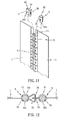
FIG. 13 is an extended out view of one male teeth element for zipper according to another alternate form of the present invention. -
FIG. 14 is an extended out view of one female teeth element for zipper according to another alternate form of the present invention. -
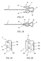
FIG. 15 is a schematic sectional view showing installation of the male teeth element ofFIG. 13 in one zipper tape (I). -
FIG. 16 is a schematic sectional view showing installation of the male teeth element ofFIG. 13 in one zipper tape (II). -
FIG. 17 is a schematic sectional view showing installation of the female teeth element ofFIG. 14 in one zipper tape (I). -
FIG. 18 is a schematic sectional view showing installation of the female teeth element ofFIG. 14 in one zipper tape (II). -
FIG. 19 is an extended out view of one male teeth element for zipper according to still another alternate form of the present invention. -
FIG. 20 is an extended out view of one female teeth element for zipper according to still another alternate form of the present invention. -
FIG. 21 is a schematic sectional view showing installation of the male teeth element ofFIG. 19 in one zipper tape (I). -
FIG. 22 is a schematic sectional view showing installation of the male teeth element ofFIG. 19 in one zipper tape (II). -
FIG. 23 is a schematic sectional view showing installation of the female teeth element ofFIG. 20 in one zipper tape (I). -
FIG. 24 is a schematic sectional view showing installation of the female teeth element ofFIG. 20 in one zipper tape (II). - Referring to
FIGS. 1 and2 , a zipper in accordance with the present invention is shown comprised of twozipper tapes 1,male teeth elements 2,female teeth elements 3, and aslider body 4. - Similar to the conventional designs, the
zipper tapes 1 each have acylindrical flange 11 extending along the length at one side. - Referring to
FIG. 5 andFIGS. 1 and 2 again, themale teeth elements 2 are arranged in series along one side of onezipper tape 1, each comprising a split tube-like base 22 fastened to thecylindrical flange 11 of the associatingzipper tape 1, ahook strip 21 perpendicularly extending from the periphery of the split tube-like base 22, and twoclamping strips 23 extending from the split tube-like base 22 and clamped on the top and bottom surface of the associatingzipper tape 1 to secure the split tube-like base 22 to thecylindrical flange 11 of the associatingzipper tape 1 firmly. The split tube-like base 22 can be made having ahole 221 at one side or each of two opposite sides to enhance engagement between the split tube-like base 22 and thecylindrical flange 11 of the associatingzipper tape 1. Thehook strip 21 has abend portion 211 extending from the periphery of the split tube-like base 22, and ahook portion 212 extending from one end of thebend portion 211 remote from the split tube-like base 22. - The
female teeth elements 3 are arranged in series along one side of theother zipper tape 1 to match themale teeth elements 2, each comprising a split tube-like base 33 fastened to thecylindrical flange 11 of the associatingzipper tape 1, a hollow receivingportion 32 protruded from the periphery of the split tube-like base 33 at one side, ahook hole 31 on the outer side of thehollow retaining portion 32, and twoclamping strips 34 extending from the split tube-like base 33 and clamped on the top and bottom surface of the associatingzipper tape 1 to secure the split tube-like base 33 to thecylindrical flange 11 of the associatingzipper tape 1 firmly (theclamping strips male teeth elements 2 orfemale teeth elements 3 may be eliminated). The split tube-like base 33 can be made having ahole 331 at one side or each of two opposite sides to enhance engagement between the split tube-like base 33 and thecylindrical flange 11 of the associatingzipper tape 1. - The
slider body 4 is movable over themale teeth elements 2 and thefemale teeth elements 3 to force themale teeth elements 2 into engagement with thefemale teeth elements 3 or to separate themale teeth elements 2 from thefemale teeth elements 3, having a guide groove 41 (seeFIG. 2 ) for guiding thehook strip 21 of eachmale teeth element 2 into thehook hole 31 of the respectivefemale teeth element 3. Further, a pull-tab 42 is coupled to theslider body 4. - Referring to
FIGS. 3 and 4 , when pulling theslider body 4 in one direction, thehook strips 21 of themale teeth elements 2 are respectively guided into thehook holes 31 of thefemale teeth elements 3 and kept engaged in thereceiving portions 32 of thefemale teeth elements 3. On the contrary, when pulling theslider body 4 in the reversed directions, thehook strips 21 of themale teeth elements 2 are respectively forced away from thehook holes 31 of thefemale teeth elements 3. - Referring to
FIGS. 6 and7 , theguide groove 41 of theslider body 4 is adapted for the passing of thehook strip 21 of eachmale teeth element 2 when theslider body 4 is moving over themale teeth elements 2 and thefemale teeth elements 3 and for guiding thehook strip 21 of eachmale teeth element 2 toward a predetermined direction so that thehook strips 21 of themale teeth elements 2 can be respectively and accurately forced into thehook holes 31 of thefemale teeth elements 3 and kept in positive engagement with thereceiving portions 32 of thefemale teeth elements 3. - Referring to
FIGS. 8 and9 , the invention can be made in the form of a close end zipper (seeFIG. 8 ) or open end zipper (seeFIG. 9 ). - In the aforesaid embodiment (see
FIGS. 1-9 ), themale teeth elements 2 and thefemale teeth elements 3 are independent elements and separately fastened to the associatingzipper tapes 1. As an alternate form of the present invention, themale teeth elements 2 and thefemale teeth elements 3 can be separately formed in integrity, i.e., theclamping strips teeth elements teeth elements zipper tapes 1, or made in one single piece and directly fastened to onezipper tape 1. - According to the present invention, the
male teeth elements 2 and thefemale teeth elements 3 can be made of metal by means of metal stamping. When the metalmale teeth elements 2 and the metalfemale teeth elements 3 are fastened to thezipper tapes 1 to form a metal zipper, the metal zipper shows a sense of ancient style. - In case a metal material is used for making the
male teeth elements 2 and thefemale teeth elements 3, themale teeth elements 2 and thefemale teeth elements 3 can be respectively stamped from a single metal sheet member. After stamping, thehook strips 21 of themale teeth elements 2 are bent into shape (seeFIG. 5 ). Except thehook strips 21, the split tube-like bases 22 (33), the clamping strips 23 (34), the holes 221 (331), the hook shape of thehook strips 21 of themale teeth elements 2 and thehook holes 31 and hollow receivingportions 32 of thefemale teeth elements 3 are all formed by means of stamping. Therefore, the fabrication of themale teeth elements 2 and thefemale teeth elements 3 is easy and quick. After fabrication, themale teeth elements 2 and thefemale teeth elements 3 can be fastened to thecylindrical flanges 11 of thezipper tapes 1 quickly and tightly. Therefore, the invention is suitable for mass production. - The receiving
portions 32 of thefemale teeth elements 3 cover the periphery of thecylindrical flange 11 of the associatingzipper tape 1 such that the receivingportions 31 of thefemale teeth elements 3 are kept in an enclosed status relative to the cylindrical flange of thecylindrical flange 11 of the associatingzipper tape 1 and thecylindrical flange 11 of the associatingzipper tape 1 will never enter the receivingportions 31 of thefemale teeth elements 3 when themale teeth elements 2 and thefemale teeth elements 3 are stretched heavily. - Further, the zipper may be variously embodied without departing from the spirit and scope of the invention.
FIGS. 10~12 show an alternate form of the zipper according to the present invention. According to this embodiment, the aforesaid clamping strips 23 and 34 are respectively eliminated from themale teeth elements 2 and thefemale teeth elements 3, and the split tube-like bases cylindrical flanges 11 of thezipper tapes 1. - According to the aforesaid embodiments, the
male teeth elements 2 and thefemale teeth elements 3 are fastened to thezipper tapes 1 by means of the split tube-like bases strips - According to another alternate form of the present invention, as shown in
FIGS. 13 and 14 , the clamping strips 23 and 34 of themale teeth elements 2 and thefemale teeth elements 3 each have a plurality ofspurs zipper tapes 1 to affix themale teeth elements 2 and thefemale teeth elements 3 to the associating zipper tapes 1 (seeFIGS. 15~18 ). Thespurts 24 of the two clampingstrips 23 of eachmale teeth element 2 are arranged in a staggered manner. Thespurts 35 of the two clampingstrips 34 of eachfemale teeth element 3 are also arranged in a staggered manner. - According to still another alternate form of the present invention, as shown in
FIGS. 19 and 20 , themale teeth elements 2 and thefemale teeth elements 3 eliminate the aforesaid clamping strips 23 and 34, and the split tube-like bases spurs zipper tapes 1 to affix themale teeth elements 2 and thefemale teeth elements 3 to the associating zipper tapes 1 (seeFIGS. 21~24 ). - Although particular embodiments of the invention have been described in detail for purposes of illustration, various modifications and enhancements may be made without departing from the scope of the invention as set out in the claims, interpreted by the description and drawings.
Claims (16)
- A zipper comprising two zipper tapes, said zipper tapes each having a cylindrical flange extending along the length thereof at one side, a plurality of male teeth elements mounted on the cylindrical flange of one of said zipper tapes and arranged in series, a plurality of female teeth elements mounted on the cylindrical flange of the other of said zipper tapes and arranged in series corresponding to said male teeth elements, and a slider body movable over said male teeth elements and said female teeth elements in reversed directions to lock and unlock said male teeth elements and said female teeth elements, wherein:said female teeth elements each comprise a split tube-like base fastened to the cylindrical flange of the associating zipper tape, a hollow receiving portion extending from the periphery of the split tube-like base of the respective female teeth element, and a hook hole on an outer side of said hollow receiving portion;said male teeth elements each comprise a split tube-like base fastened to the cylindrical flange of the associating zipper tape, and a hook strip extending from the periphery of the split tube-like base of the respective male teeth element and guidable by said slider body into and out of the hook hole on the hollow receiving portion of the associating female teeth element.
- The zipper as claimed in claim 1, wherein said male teeth elements each comprise two clamping strips extending from the respective split tube-like base and respectively clamped on top and bottom surfaces of the associating zipper tape to affix the respective male teeth element to the associating zipper tape.
- The zipper as claimed in claim 1 or 2, wherein said male teeth elements each have at least one hole cut through the periphery of the respective split tube-like base.
- The zipper as claimed in claim 1, 2 or 3, wherein the hook strip of each of said male teeth elements has a bend portion extending from the periphery of the split tube-like base and a hook portion extending from one end of said bend portion remote from the split tube-like base of the respective male teeth element.
- The zipper as claimed in any one of claims 1 to 4, wherein said female teeth elements each comprise two clamping strips extending from the respective split tube-like base and respectively clamped on top and bottom surfaces of the associating zipper tape to affix the respective male teeth element to the associating zipper tape.
- The zipper as claimed in any one of claims 1 to 5, wherein said female teeth elements each have at least one hole cut through the periphery of the respective split tube-like base.
- The zipper as claimed in any one of claims 1 to 6, wherein said slider body comprises a guide groove for guiding the hook strip of each of said male teeth elements in and out of the hook holes of the associating female teeth elements.
- The zipper as claimed in any one of claims 1 to 7, wherein said male teeth elements and said female teeth elements are independent elements separately fastened to said zipper tapes.
- The zipper as claimed in any one of claims 1 to 8, wherein said male teeth elements are formed integrally in a single piece; said female teeth elements are formed integrally in a single piece.
- The zipper as claimed in any one of claims 1 to 9, wherein said male teeth elements are integrally connected together before installation in the associating zipper tape; said female teeth elements are integrally connected together before installation in the associating zipper tape.
- The zipper as claimed in any one of claims 1 to 10, wherein said male teeth elements are made in integrity from a metal plate by means of metal stamping; said female teeth elements are made in integrity from a metal plate by means of metal stamping.
- The zipper as claimed in any one of claims 1 to 11, wherein the split tube-like bases of said male teeth elements and said female teeth elements are respectively tightly clamped on the cylindrical flanges of said zipper tapes.
- The zipper as claimed in any one of claims 1 to 12, wherein the split tube-like bases of said female teeth elements cover the periphery of the cylindrical flange of the associating zipper tape such that said receiving portions of said female teeth elements are kept in an enclosed status relative to the cylindrical flange of the associating zipper tape.
- The zipper as claimed in any one of claims 1 to 13, wherein said clamping strips of said male teeth elements and said female teeth elements each have a plurality of spurs protruded from an inner surface thereof and respectively engaged into said zipper tapes.
- The zipper as claimed in any one of claims 1 to 14, wherein the split tube-like bases of said male teeth elements and said female teeth elements each have a plurality of spurs protruded from two ends thereof and respectively engaged into said zipper tapes.
- A zipper comprising two zipper tapes, a series of male teeth elements provided at one zipper tape, a series of female teeth elements provided at the other zipper tape, and a slider body movable over the male teeth elements and the female teeth elements to lock the male teeth elements and the female teeth elements or to unlock the male teeth elements from the female teeth elements wherein the female teeth elements each have a receiving portion and a hook hole on the outer side of the receiving portion and the male teeth elements each have a hook strip guided by the slider body into and out of the hook holes of the female teeth elements.
Priority Applications (1)
| Application Number | Priority Date | Filing Date | Title |
|---|---|---|---|
| EP07254217A EP2052639A1 (en) | 2007-10-24 | 2007-10-24 | Zipper |
Applications Claiming Priority (1)
| Application Number | Priority Date | Filing Date | Title |
|---|---|---|---|
| EP07254217A EP2052639A1 (en) | 2007-10-24 | 2007-10-24 | Zipper |
Publications (1)
| Publication Number | Publication Date |
|---|---|
| EP2052639A1 true EP2052639A1 (en) | 2009-04-29 |
Family
ID=39273265
Family Applications (1)
| Application Number | Title | Priority Date | Filing Date |
|---|---|---|---|
| EP07254217A Withdrawn EP2052639A1 (en) | 2007-10-24 | 2007-10-24 | Zipper |
Country Status (1)
| Country | Link |
|---|---|
| EP (1) | EP2052639A1 (en) |
Cited By (2)
| Publication number | Priority date | Publication date | Assignee | Title |
|---|---|---|---|---|
| WO2017084552A1 (en) * | 2015-11-17 | 2017-05-26 | 吴弘纳 | Zipper teeth, puller and zipper having zipper teeth and puller |
| CN114532672A (en) * | 2022-04-02 | 2022-05-27 | 温州日成拉链有限公司 | Degradable injection-molded zipper and preparation method thereof |
Citations (9)
| Publication number | Priority date | Publication date | Assignee | Title |
|---|---|---|---|---|
| US624927A (en) | 1899-05-16 | Elias gunnell | ||
| US1746565A (en) * | 1926-09-22 | 1930-02-11 | Hookless Fastener Co | Separable fastener |
| US1934084A (en) | 1930-08-22 | 1933-11-07 | Hookless Fastener Co | Separable fastener |
| US2991528A (en) * | 1959-03-03 | 1961-07-11 | Irving Constant | Metal slide fasteners and method of making same |
| US3872551A (en) | 1973-07-06 | 1975-03-25 | Textron Inc | Slide fastener having separating end stop |
| US4099301A (en) | 1975-11-22 | 1978-07-11 | Yoshida Kogyo K.K. | Slide fastener combination |
| US6243927B1 (en) * | 1998-04-28 | 2001-06-12 | Ykk Corporation | Slide fastener |
| US6588072B1 (en) | 2001-12-31 | 2003-07-08 | Yu-Pau Lin | Zipper slide |
| US7036191B2 (en) | 2003-04-21 | 2006-05-02 | Chang-Wen Tsaur | Lower stop of zipper |
-
2007
- 2007-10-24 EP EP07254217A patent/EP2052639A1/en not_active Withdrawn
Patent Citations (9)
| Publication number | Priority date | Publication date | Assignee | Title |
|---|---|---|---|---|
| US624927A (en) | 1899-05-16 | Elias gunnell | ||
| US1746565A (en) * | 1926-09-22 | 1930-02-11 | Hookless Fastener Co | Separable fastener |
| US1934084A (en) | 1930-08-22 | 1933-11-07 | Hookless Fastener Co | Separable fastener |
| US2991528A (en) * | 1959-03-03 | 1961-07-11 | Irving Constant | Metal slide fasteners and method of making same |
| US3872551A (en) | 1973-07-06 | 1975-03-25 | Textron Inc | Slide fastener having separating end stop |
| US4099301A (en) | 1975-11-22 | 1978-07-11 | Yoshida Kogyo K.K. | Slide fastener combination |
| US6243927B1 (en) * | 1998-04-28 | 2001-06-12 | Ykk Corporation | Slide fastener |
| US6588072B1 (en) | 2001-12-31 | 2003-07-08 | Yu-Pau Lin | Zipper slide |
| US7036191B2 (en) | 2003-04-21 | 2006-05-02 | Chang-Wen Tsaur | Lower stop of zipper |
Cited By (2)
| Publication number | Priority date | Publication date | Assignee | Title |
|---|---|---|---|---|
| WO2017084552A1 (en) * | 2015-11-17 | 2017-05-26 | 吴弘纳 | Zipper teeth, puller and zipper having zipper teeth and puller |
| CN114532672A (en) * | 2022-04-02 | 2022-05-27 | 温州日成拉链有限公司 | Degradable injection-molded zipper and preparation method thereof |
Similar Documents
| Publication | Publication Date | Title |
|---|---|---|
| US20090113676A1 (en) | Zipper | |
| EP1201144B1 (en) | Slider for airtight and watertight slide fastener | |
| JP4726876B2 (en) | Reverse opening slide fastener | |
| US7698790B2 (en) | Stop for slide fasteners | |
| US9220323B2 (en) | Slider provided with handle at rear for slide fastener | |
| KR100988389B1 (en) | Slider for double-sided slide fastener with automatic locking device | |
| TW201212840A (en) | Slider for slide fasteners with attached automatic stopping device | |
| EP1714575A1 (en) | Top end stops for slide fastener | |
| JP2007097840A (en) | Waterproof slide fastener | |
| JP2008212352A (en) | Teeth for zipper, and zipper | |
| JP6027653B2 (en) | Sealing for open end slide fasteners | |
| JP2007111351A (en) | Slider for slide fastener with automatic stop device | |
| WO2010041303A1 (en) | Slide fastener | |
| EP2904922B1 (en) | Slide fastener | |
| CN109843110B (en) | Zipper assembly | |
| CA1282941C (en) | Fluid-tight slide fastener | |
| US20020116798A1 (en) | Upper stopper device for slide fastener | |
| JP5247823B2 (en) | Slide fastener with open fitting insert | |
| JPS5932329Y2 (en) | Slide fastener with release tool | |
| EP2052639A1 (en) | Zipper | |
| EP0745338A2 (en) | Automatic lock slider for slide fastener | |
| KR100786000B1 (en) | A slide fastener | |
| EP1430804B1 (en) | Concealed type slide fastener | |
| US8931145B1 (en) | Sliding zipper controller | |
| US4651388A (en) | Sliding clasp fastener |
Legal Events
| Date | Code | Title | Description |
|---|---|---|---|
| PUAI | Public reference made under article 153(3) epc to a published international application that has entered the european phase |
Free format text: ORIGINAL CODE: 0009012 |
|
| AK | Designated contracting states |
Kind code of ref document: A1 Designated state(s): AT BE BG CH CY CZ DE DK EE ES FI FR GB GR HU IE IS IT LI LT LU LV MC MT NL PL PT RO SE SI SK TR |
|
| AX | Request for extension of the european patent |
Extension state: AL BA HR MK RS |
|
| 17P | Request for examination filed |
Effective date: 20090929 |
|
| 17Q | First examination report despatched |
Effective date: 20091023 |
|
| AKX | Designation fees paid |
Designated state(s): AT BE BG CH CY CZ DE DK EE ES FI FR GB GR HU IE IS IT LI LT LU LV MC MT NL PL PT RO SE SI SK TR |
|
| STAA | Information on the status of an ep patent application or granted ep patent |
Free format text: STATUS: THE APPLICATION IS DEEMED TO BE WITHDRAWN |
|
| 18D | Application deemed to be withdrawn |
Effective date: 20120501 |