EP2052637A1 - Button - Google Patents
Button Download PDFInfo
- Publication number
- EP2052637A1 EP2052637A1 EP07805898A EP07805898A EP2052637A1 EP 2052637 A1 EP2052637 A1 EP 2052637A1 EP 07805898 A EP07805898 A EP 07805898A EP 07805898 A EP07805898 A EP 07805898A EP 2052637 A1 EP2052637 A1 EP 2052637A1
- Authority
- EP
- European Patent Office
- Prior art keywords
- button
- cloth
- insert
- prong
- aluminum alloy
- Prior art date
- Legal status (The legal status is an assumption and is not a legal conclusion. Google has not performed a legal analysis and makes no representation as to the accuracy of the status listed.)
- Granted
Links
Images


Classifications
-
- A—HUMAN NECESSITIES
- A44—HABERDASHERY; JEWELLERY
- A44B—BUTTONS, PINS, BUCKLES, SLIDE FASTENERS, OR THE LIKE
- A44B1/00—Buttons
- A44B1/02—Buttons characterised by their material
-
- A—HUMAN NECESSITIES
- A44—HABERDASHERY; JEWELLERY
- A44B—BUTTONS, PINS, BUCKLES, SLIDE FASTENERS, OR THE LIKE
- A44B1/00—Buttons
- A44B1/18—Buttons adapted for special ways of fastening
-
- Y—GENERAL TAGGING OF NEW TECHNOLOGICAL DEVELOPMENTS; GENERAL TAGGING OF CROSS-SECTIONAL TECHNOLOGIES SPANNING OVER SEVERAL SECTIONS OF THE IPC; TECHNICAL SUBJECTS COVERED BY FORMER USPC CROSS-REFERENCE ART COLLECTIONS [XRACs] AND DIGESTS
- Y10—TECHNICAL SUBJECTS COVERED BY FORMER USPC
- Y10T—TECHNICAL SUBJECTS COVERED BY FORMER US CLASSIFICATION
- Y10T24/00—Buckles, buttons, clasps, etc.
- Y10T24/36—Button with fastener
- Y10T24/3611—Deflecting prong or rivet
-
- Y—GENERAL TAGGING OF NEW TECHNOLOGICAL DEVELOPMENTS; GENERAL TAGGING OF CROSS-SECTIONAL TECHNOLOGIES SPANNING OVER SEVERAL SECTIONS OF THE IPC; TECHNICAL SUBJECTS COVERED BY FORMER USPC CROSS-REFERENCE ART COLLECTIONS [XRACs] AND DIGESTS
- Y10—TECHNICAL SUBJECTS COVERED BY FORMER USPC
- Y10T—TECHNICAL SUBJECTS COVERED BY FORMER US CLASSIFICATION
- Y10T24/00—Buckles, buttons, clasps, etc.
- Y10T24/36—Button with fastener
- Y10T24/3611—Deflecting prong or rivet
- Y10T24/3613—Anvil or plate
Definitions
- This invention relates to a button made of metal, and particularly to a button of which at least a button back is manufactured from aluminum or an aluminum alloy in order to manufacture the button at low cost and simply.
- a button of the type in which a fastener called a prong having projected leg members pierces cloth to which a body of the button is attached from the back of the cloth and these leg members are fixedly secured to the button body to attach the button to the cloth is known from old times, as disclosed in Patent Literature 1 and Patent Literature 2, for example.
- a fastener called a prong having projected leg members pierces cloth to which a body of the button is attached from the back of the cloth and these leg members are fixedly secured to the button body to attach the button to the cloth.
- the conventional metal buttons include, for example, a button 1 which comprises a button body 10 containing an insert (accommodated member) 11 surrounded by an outer shell member 13 consisting of a cap 14 and a button back 15 and a fastener 20 called a prong (tack) to be arranged so as to nip the cloth 30 between the button body and the fastener and having two leg members 21, as shown in Fig. 1 and Fig.
- a button 1 which comprises a button body 10 containing an insert (accommodated member) 11 surrounded by an outer shell member 13 consisting of a cap 14 and a button back 15 and a fastener 20 called a prong (tack) to be arranged so as to nip the cloth 30 between the button body and the fastener and having two leg members 21, as shown in Fig. 1 and Fig.
- buttons 1a which comprises a button body 10a containing an insert 11a made of resin of which upper and side surfaces are surrounded by an outer shell member consisting of a cap 14a and a button back 15a and a prong (tack) 20a having a single leg member 21a of the arrowhead shape, which is to be arranged so as to nip the cloth between the button body and the prong, as shown in Fig.
- buttons (B) wherein the button is attached to the cloth 30 by making the prong 20a to pierce the cloth 30 and press-fitting the arrowhead-like leg member 21a into a hole 12a of the insert 11a made of resin so that it is fixedly secured to the button body by the aid of the anchor effect of its leading end (hereinafter referred to as a metal button (B)).
- caps 14 and 14a which have been used are either one of the followings:
- the inserts 11 and 11a are the parts to be built into the inside of the button body for the purpose of absorbing the shock at the time of attachment of the button, guiding the leading end parts of the prong leg members at the time of bending (curling) thereof, and preventing the prong leg members from being left out.
- the metal button (A) either of (1) the insert manufactured by cold casting iron or low-carbon steel into a predetermined shape or (2) the insert manufactured by molding a zinc alloy into a predetermined shape by die casting has been used.
- the insert manufactured by injection molding a resin into a predetermined shape has been used.
- the button backs 15 and 15a which have been used are either of (1) the button back manufactured by cold pressing a plate material of a copper-zinc alloy to a predetermined shape and subjecting it to a silver white plating treatment from the viewpoint of its design or (2) the button back manufactured by cold pressing a linear material of stainless steel of which alloy color tone is silver white to a predetermined shape.
- a metal button is attached to such cloth as jeans and trucker jackets or denim jackets.
- Most of the button backs have the color tone of silver white so as to make a high-grade impression etc. on people.
- either of (1) a copper-zinc alloy subjected to silver white plating or (2) stainless steel having the alloy color tone of white is used.
- the above material (1) has the alloy color tone of yellow, the high-grade impression is inferior to the whitish materials. Accordingly, the above material should be subjected to a silver white plating treatment to produce the high-grade impression.
- the plating treatment increases the working steps and will exert a harmful influence on a human body depending on the kind of plating. Moreover, there is a possibility of polluting environment due to a waste water treatment, for example, accompanying the plating treatment (environment load is large).
- environment load is large.
- the alloy color tone of stainless steel material is silver white
- its workability of cold pressing is inferior to a copper-zinc alloy, the life of a pressing mold is short, which requires frequent exchange of the metal molds, and the load exerting on environment is large.
- the present invention has been made to solve the problems of the conventional technology as described above and has an object to provide a button which can be manufactured simply and at low cost by a method of plating-free, particularly a whitish button which could be heretofore obtained only by plating.
- the present invention provides a button which comprises a button body and a fastener adapted to be arranged on the side of cloth opposite to the side thereof on which the button body is set in place to nip the cloth therebetween and to fixedly secure the button body to the cloth, the button body mentioned above containing an outer shell member, which comprises a button back and a cap, and an insert accommodated in the outer shell member, characterized in that at least the button back mentioned above is made of aluminum or an aluminum alloy.
- the button back mentioned above is made of an aluminum alloy containing 3-6% by weight of magnesium, and the cross-sectional thickness of the above-mentioned button back is in the range of 0.25-0.6 mm.
- the Vickers hardness of a side portion of the button back mentioned above is Hv 110-140, and the Vickers hardness of a portion of the button back with which the prong mentioned above comes into contact is Hv 80-105.
- the above-mentioned cap and the insert should also be made of an aluminum alloy.
- the button back portion is formed from aluminum or an aluminum alloy, it is possible to provide a whitish button back, which has heretofore been obtained only by plating, by a plating-free method. Consequently, a button can be manufactured simply and at low cost, without requiring the conventional plating process and the liquid waste treatment accompanying the plating treatment and without producing the problem of environmental pollution. Moreover, since aluminum or an aluminum alloy has high ductility, the button back excels in the shock absorption properties when the fastener is attached thereto and the bottom thereof will not be cracked.
- the button back mentioned above is made of an aluminum alloy containing 3-6% by weight of magnesium and the cross-sectional thickness of the above-mentioned button back is in the range of 0.25-0.6 mm, it is possible to secure sufficient strength.
- the Vickers hardness of a side portion of the button back mentioned above is Hv 110-140 and the Vickers hardness of a portion of the button back with which the prong mentioned above comes into contact is Hv 80-105, the fastener can be attached to the bottom of the button back without causing cracks therein and also without producing deformation in the side portion of the button back, and it is therefore possible to provide a button excelling in reliability.
- the above-mentioned cap and the insert from an aluminum alloy, it is possible to attain weight-saving of the produced button and to provide the button excelling in recycling efficiency because of not requiring separation and selection of parts when recycled.
- a button which comprises a button body and a fastener adapted to be arranged on the side of cloth opposite to the side thereof on which the button body is set in place to nip the cloth therebetween and to fixedly secure the button body to the cloth
- the button body mentioned above containing an outer shell member, which comprises a button back and a cap, and an insert accommodated in the outer shell member, by forming at least the button back from aluminum or an aluminum alloy, it has made possible to provide a whitish button back, which has heretofore been obtained only by plating, by a plating-free method.
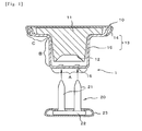
- Fig. 1 and Fig. 2 show the metal button (A) mentioned above.
- This button 1 consists of a button body 10, which comprises an insert (accommodated member) 11 having an upper portion extended in the shape of a disk and an outer shell member 13 which comprises a button back 15 surrounding the insert and a cap 14 disposed thereon so as to cover them, and a fastener 20 called a prong (tack) which has two leg members 21 and is to be arranged on opposite side of the cloth 30 so as to nip the cloth between the button body and the fastener.
- a button body 10 which comprises an insert (accommodated member) 11 having an upper portion extended in the shape of a disk and an outer shell member 13 which comprises a button back 15 surrounding the insert and a cap 14 disposed thereon so as to cover them, and a fastener 20 called a prong (tack) which has two leg members 21 and is to be arranged on opposite side of the cloth 30 so as to nip the cloth between the button body and the fast
- the button back 15 consists of a disk-like bottom "A", a cylindrical side portion “B” raised from the circumferential edge of the bottom “A” mentioned above, and an annular upper dish-like portion “C” which is laterally extending in the radial direction from the upper end of the side portion "B” mentioned above and has a side portion raised upward so as to surround the upper portion of the insert 11 mentioned above extending in the shape of a disk.
- the insert (accommodated member) 11 has a recess 12 which is formed in the bottom thereof and functions as a guiding part for bending (curling) the leading end portion of the prong 20 when the leg members 21 of the prong 20 pierce the button back.
- the button back 15 has two depressed areas 16 which are formed in the bottom "A" thereof and function as guiding parts when the two leg members 21 of the prong 20 are pushed to pierce the button back.
- the prong 20 has a pair of leg members 21 raised from a disk-like base 22, and the circumference of the base 22 is covered with a cap 23.
- Fig. 3 shows the metal button (B) mentioned above.
- This button 1a consists of a button body 10a, which comprises an insert 11a made of resin and having an upper portion extended in the shape of a disk and an outer shell member comprising a cap 14a and a button back 15a and surrounding the upper part and the side of the insert respectively, and a prong 20a which is to be arranged on the opposite side of the cloth so as to nip the cloth between the button body and the prong and has a single leg member 21a of the arrowhead shape.
- the button back 15a consists of a cylindrical side portion "B" having no bottom portion and an annular upper dish-like portion "C” which is laterally extending in the radial direction from the upper end of the side portion "B” mentioned above and has a curved side portion raised upward so as to surround the upper portion of the insert 11 mentioned above extending in the shape of a disk.
- the annular upper dish-like portion "C” has a step portion formed between the portion laterally extending in the radial direction and the curved side portion raised upward, it may be flat like the upper dish-like portion "C" of the button back 15 shown in Fig. 1 and Fig. 2 .
- the insert 11a made of resin has a hole 12a formed therein so as to vertically run therethrough and its bottom is exposed.
- the prong 20a has such a form that a single leg member 21a of the arrowhead shape is raised from the center of a disk-like base 22a.
- Fig. 4 shows an example of another metal button.
- This button 1b consists of a button body 10b, which comprises a button back 15b, a disk-like insert 11b laid on the upper extending portion of the button back, and a cap 14b disposed thereon so as to cover the upper parts thereof, and a prong (tack) 20b which has a single leg member 21b and is to be arranged on opposite side of the cloth so as to nip the cloth between the button body and the prong.
- upwardly tapering split cylindrical guide parts 17 are raised from the flat ring-like bottom "A" of the button back 15b in the upward direction from the circumferential edge of its center hole to the cap 14b, other structure is the same as that of the button back 15 shown in Fig.
- the prong 20b has such a form that a single leg member 21b having a leading end bulge portion is raised from the center of a disk-like base part 22b and the circumference of the base 22b is covered with a cap 23b.
- the prong 20b arranged on the side of the cloth 30 opposite to the side thereof on which the button body 10b is set in place so as to nip the cloth therebetween is pushed therein. Consequently, the leg member 21b pierces the cloth 30 and is press-fitted into the guide part 17 of the button back 15b, as shown in Fig. 4 , so that the button can be attached to the cloth 30 by the aid of the detachment preventing effect of the leading end bulge portion of the leg member.
- the component made of a Cu-Zn alloy or a zinc alloy which had been subjected to a decorative treatment is generally used as the cap (14, 14a, 14b) of the button body, it is not limited to a particular one.
- the insert 11 is a member for carrying out the curling of the leg members 21 of the prong 20 and fixedly securing the button to the cloth.
- iron or low-carbon steel which has the predetermined strength and has been subjected to zinc plating or a zinc alloy is used for the portion (recess 12 in the bottom) which comes into contact with the leg members 21 of the prong 20.
- any material may be used insofar as it makes the curling of the leg members 21 of the prong 20 possible.
- Particularly preferred insert of the present invention is manufactured from an aluminum alloy, which makes possible to provide a recyclable button with lightweight.
- the button back 15 and the insert 11 are formed of the material of the same quality, it makes possible to provide a button which will not cause potential difference corrosion due to the contact of the insert with the button back, which had heretofore often come into question.
- the insert is manufactured from an aluminum alloy like the present invention, attention should be directed to the following points. Since the insert is made of an aluminum alloy, the required hardness will not be obtained if the insert is manufactured by a die casting method which has been used heretofore. Therefore, the insert is manufactured by the cold working of an aluminum alloy. For example, it is desirable that an aluminum alloy containing a predetermined amount of magnesium be subjected to the cold working to form a product of a predetermined shape having the Vickers hardness of not less than Hv 90. It is more preferable to manufacture the insert of which portion (dome-like recess 12) coming into contact with the prong 20 (fastener) has the Vickers hardness of not less than Hv 110.
- the insert will have high fixing strength and will be hardly corroded.
- the Vickers hardness is lower than Hv 90, the leg member 21 of the prong 20 will not be firmly curled, which results in insufficient fixing strength.
- the upper limit of the Vickers hardness is restricted to about Hv 150 in view of the properties of an aluminum alloy, the proper range is from Hv 90 to Hv 150 if the upper limit is taken into consideration.
- the aluminum alloy used for the insert should contain magnesium in the range of 3% to 6% by weight. If the magnesium content is less than 3% by weight, the degree of work-hardening at the time of the cold pressing will become low and a predetermined hardness will not be obtained after molding. As a result, it will be hardly possible to attach the button to the cloth securely by taking advantage of the curling of the prong. Conversely, if the magnesium content is more than 6% by weight, the resultant alloy will exhibit inferior cold forming properties. As a result, the obtained insert tends to generate cracks when the button body is attached to the cloth by the use of the prong. Furthermore, the insert tends to generate stress corrosion cracking and its corrosion resistance will become inferior.
- the insert 11a fixes the button to the cloth firmly by strongly fixing the leg member 21a of the arrowhead shape of the prong 20a to its hole 12a
- the insert made of a synthetic resin is used.
- the insert 11b may be a flat plate.
- the button back (15, 15a, 15b) is a member which constitutes an outer shell of a button and adapted to contain the insert (11, 11a, 11b) therein. Since the button back of the present invention is made of aluminum or an aluminum alloy, unlike the conventional one, it is not required to be subjected to white plating.
- the button back is made of an aluminum alloy
- the magnesium content therein exerts an influence on the form and the size of the button back after the cold pressing, particularly exerts a great influence on the attachment of a metal button.
- the aluminum alloy used for the button back should contain magnesium in the range of 3% to 6% by weight. If the magnesium content is less than 3% by weight, the degree of work-hardening at the time of the cold pressing will become low and a predetermined hardness will not be obtained after molding.
- the metal button (A) shown in Fig. 1 and Fig. 2 it will be difficult to obtain the fixing strength equal to or more than that of the present button back, so that a button will come off the cloth when the button is used.
- the resultant alloy will exhibit inferior cold forming properties.
- the button back tends to generate cracks when it is attached to the cloth by the use of the fastener (prong). Moreover, the button back tends to generate stress corrosion cracking and its corrosion resistance will become inferior.
- the cross-sectional thickness of the button back (15, 15a, 15b) will be described. Since the cross-sectional thickness after the cold pressing exerts a great influence on the form and the size of the button back and also on the attachment of the metal button (A). Accordingly, it is desirable that the cross-sectional thickness of the button back be in the range of 0.25 to 0.6 mm. If the cross-sectional thickness is smaller than 0.25 mm, it will be difficult to obtain the fixing strength equal to or more than that of the present button back. Moreover, when the metal button is attached to the cloth by means of the fastener (prong), its shock will deform the side portion of the button back and impair its design. Similarly, in the case of the metal button (B), when the fastener is attached to the insert made of resin, its shock will deform the side portion of the button back.
- cross-sectional thickness is larger than 0.6 mm, in the case of the metal button (A) the penetration characteristics of the leg member will become inferior when the button is attached to the cloth by the use of the fastener (prong) having two leg members made of a copper-zinc alloy. As a result, it will be difficult to obtain the fixing strength equal to or more than that of the present button back. Further, in both the metal button (A) and the metal button (B), the size of the button becomes large, which will impair its design and lead to an increase in cost. In order to secure sufficient fixing strength, the cross-sectional thickness of the button back is desired to be such size that the thickness of the bottom "A" is smaller than those of the upper dish-like portion "C" and the side portion "B".
- the hardness of the button back (15, 15a, 15b) will be described.
- the hardness of the bottom of the button back i.e. the portions (depressed areas 16) through which the prong 20 contacts and penetrates
- the fixing strength of the metal button (A) If the Vickers hardness is in the range of Hv 80 to 105, it is possible to obtain the fixing strength equal to or more than that of the present button back. However, if the hardness is lower than the above range, the fixing strength of the button will become low and there is a possibility that the button may come off the cloth when the button is used.
- the side portion "B” and the upper dish-like portion “C" exposed in the side of the button back (15, 15a, 15b) of the present invention are the portions exposed outside when it is attached to the cloth, their hardness, particularly the hardness of the side portion "B” has a close relation to the design (form and size) of the metal button. If their hardness, at least the hardness of the side portion "B” in Vickers hardness is not less than Hv 110 and not more than Hv 140, preferably in the range of Hv 110-130, all of the metal button (A) shown in Fig. 1 and Fig. 2 , the metal button (B) shown in Fig. 3 , and the metal button shown in Fig.
- the prong (20, 20a, 20b) is a member used for attaching the button to the cloth.
- the button having the form shown in Fig. 1 through Fig. 4 may be cited.
- a material having a certain degree of strength and exhibiting high ductility such as a Cu-Zn alloy and a stainless steel alloy, for example, is used as a material thereof.
- the prong is required to be press-fitted into the hole 12a formed in the insert 11a made of resin or into the split cylindrical guide part 17 raised from the central part of the insert 11b while deforming it for attachment to the cloth, a material such as an aluminum alloy, for example, is used as a material thereof.
- a linear A5182 aluminum alloy material, 0.45 mm in thickness and the tempering condition of O-material (the most soft state, which had been subjected to an annealing treatment), was subjected to the cold pressing with a pressing machine to manufacture a button back as shown in Fig. 1 . Thereafter, a button was assembled using a cap made of brass and an insert made by zinc die casting by means of a button back assembly machine and attached to cloth by the use of a prong made of a Cu-Zn alloy.
- the hardness distribution measured with a Vickers hardness tester and the fixing strength of the obtained button were evaluated in such manner that the button which showed the strength equal to the strength obtained from the metal button using the conventional button back was rated as ⁇ and the button which showed the strength lower than the strength obtained from the metal button using the conventional button back was rated as ⁇ . Further, the presence or absence of deformation thereof at the time of attachment to the cloth was visually examined. The results are shown in Table 1.
- the present invention allows the manufacture of a whitish button, which has heretofore been obtained only by plating, by a plating-free method simply and at low cost, it may be applicable to buttons of various forms.
Landscapes
- Slide Fasteners, Snap Fasteners, And Hook Fasteners (AREA)
Abstract
Description
- This invention relates to a button made of metal, and particularly to a button of which at least a button back is manufactured from aluminum or an aluminum alloy in order to manufacture the button at low cost and simply.
- A button of the type in which a fastener called a prong having projected leg members pierces cloth to which a body of the button is attached from the back of the cloth and these leg members are fixedly secured to the button body to attach the button to the cloth is known from old times, as disclosed in
Patent Literature 1 and Patent Literature 2, for example. In the case of a metal button, generally such type of button is adopted. - The conventional metal buttons include, for example, a
button 1 which comprises abutton body 10 containing an insert (accommodated member) 11 surrounded by anouter shell member 13 consisting of acap 14 and a button back 15 and afastener 20 called a prong (tack) to be arranged so as to nip thecloth 30 between the button body and the fastener and having twoleg members 21, as shown inFig. 1 andFig. 2 , wherein the button is attached to the cloth by making theprong 20 to pierce thecloth 30 so as to make a hole in the bottom of the button back 15 and simultaneously to be bent (curled) by the aid of a curved surface of arecess 12 of theinsert 11 so that it is fixedly secured to the button body 10 (hereinafter referred to as a metal button (A)); and abutton 1a which comprises abutton body 10a containing aninsert 11a made of resin of which upper and side surfaces are surrounded by an outer shell member consisting of acap 14a and abutton back 15a and a prong (tack) 20a having asingle leg member 21a of the arrowhead shape, which is to be arranged so as to nip the cloth between the button body and the prong, as shown inFig. 3 , wherein the button is attached to thecloth 30 by making theprong 20a to pierce thecloth 30 and press-fitting the arrowhead-like leg member 21a into ahole 12a of theinsert 11a made of resin so that it is fixedly secured to the button body by the aid of the anchor effect of its leading end (hereinafter referred to as a metal button (B)). - In both the metal button (A) and the metal button (B), the above-mentioned
caps - (1) the cap manufactured by cold pressing a linear material of a copper-zinc alloy to a predetermined shape and subjecting it to various plating treatments from the viewpoint of its design,
- (2) the cap manufactured by cold pressing a linear material of an aluminum alloy to a predetermined shape and subjecting it to an alumite treatment (an anodic oxidation treatment) from the viewpoint of its design, and
- (3) the cap manufactured by cold pressing a linear material of stainless steel to a predetermined shape.
- The
inserts - Furthermore, in both the metal button (A) and the metal button (B), the
button backs - Patent Literature 1:
U.S. Patent Specification No. 1,463,236 - Patent Literature 2:
U.S. Patent Specification No. 1,378,108 - Generally a metal button is attached to such cloth as jeans and trucker jackets or denim jackets. Most of the button backs have the color tone of silver white so as to make a high-grade impression etc. on people. In order to secure the required fixing strength so that the above-mentioned button back may certainly not come off the cloth after completion of attachment thereof to the cloth by the aid of the prong, either of (1) a copper-zinc alloy subjected to silver white plating or (2) stainless steel having the alloy color tone of white is used. However, since the above material (1) has the alloy color tone of yellow, the high-grade impression is inferior to the whitish materials. Accordingly, the above material should be subjected to a silver white plating treatment to produce the high-grade impression. However, the plating treatment increases the working steps and will exert a harmful influence on a human body depending on the kind of plating. Moreover, there is a possibility of polluting environment due to a waste water treatment, for example, accompanying the plating treatment (environment load is large). On the other hand, as for the above material (2), since the alloy color tone of stainless steel material is silver white, there is no need to purposely perform the plating treatment of silver white. However, since its workability of cold pressing is inferior to a copper-zinc alloy, the life of a pressing mold is short, which requires frequent exchange of the metal molds, and the load exerting on environment is large.
- The present invention has been made to solve the problems of the conventional technology as described above and has an object to provide a button which can be manufactured simply and at low cost by a method of plating-free, particularly a whitish button which could be heretofore obtained only by plating.
- To accomplish the above-mentioned object, the present invention provides a button which comprises a button body and a fastener adapted to be arranged on the side of cloth opposite to the side thereof on which the button body is set in place to nip the cloth therebetween and to fixedly secure the button body to the cloth, the button body mentioned above containing an outer shell member, which comprises a button back and a cap, and an insert accommodated in the outer shell member, characterized in that at least the button back mentioned above is made of aluminum or an aluminum alloy.
- In a preferred embodiment, the button back mentioned above is made of an aluminum alloy containing 3-6% by weight of magnesium, and the cross-sectional thickness of the above-mentioned button back is in the range of 0.25-0.6 mm. In a more preferred embodiment, the Vickers hardness of a side portion of the button back mentioned above is Hv 110-140, and the Vickers hardness of a portion of the button back with which the prong mentioned above comes into contact is Hv 80-105.
Furthermore, it is desirable that the above-mentioned cap and the insert should also be made of an aluminum alloy. - According to the present invention, since the button back portion is formed from aluminum or an aluminum alloy, it is possible to provide a whitish button back, which has heretofore been obtained only by plating, by a plating-free method. Consequently, a button can be manufactured simply and at low cost, without requiring the conventional plating process and the liquid waste treatment accompanying the plating treatment and without producing the problem of environmental pollution. Moreover, since aluminum or an aluminum alloy has high ductility, the button back excels in the shock absorption properties when the fastener is attached thereto and the bottom thereof will not be cracked.
- Furthermore, according to the preferred embodiment of the present invention, since the button back mentioned above is made of an aluminum alloy containing 3-6% by weight of magnesium and the cross-sectional thickness of the above-mentioned button back is in the range of 0.25-0.6 mm, it is possible to secure sufficient strength. In a more preferred embodiment, since the Vickers hardness of a side portion of the button back mentioned above is Hv 110-140 and the Vickers hardness of a portion of the button back with which the prong mentioned above comes into contact is Hv 80-105, the fastener can be attached to the bottom of the button back without causing cracks therein and also without producing deformation in the side portion of the button back, and it is therefore possible to provide a button excelling in reliability. Further, by manufacturing the above-mentioned cap and the insert from an aluminum alloy, it is possible to attain weight-saving of the produced button and to provide the button excelling in recycling efficiency because of not requiring separation and selection of parts when recycled.
-
- [
Fig. 1 ] An exploded cross-sectional view illustrating an example of a metal button to which the present invention is applied. - [
Fig. 2 ] A cross-sectional view illustrating the state where the metal button shown inFig. 1 is attached to the cloth and assembled. - [
Fig. 3 ] A cross-sectional view illustrating another example of the metal button to which the present invention is applied in the state where it is attached to the cloth and assembled. - [
Fig. 4 ] A cross-sectional view illustrating still another example of the metal button to which the present invention is applied in the state where it is attached to the cloth and assembled. -
- 1, 1a, 1b: Button
- 10, 10a, 10b: Button Body
- 11, 11a, 11b: Insertion (accommodated member)
- 13: Outer Shell Member
- 14, 14a, 14b: Cap
- 15, 15a, 15b: Button Back
- 20, 20a, 20b: Prong (Fastener)
- 21, 21a, 21b: Leg Member
- A: Bottom
- B: Side Portion
- C: Upper Dish-like Portion
- In accordance with the present invention, in a button which comprises a button body and a fastener adapted to be arranged on the side of cloth opposite to the side thereof on which the button body is set in place to nip the cloth therebetween and to fixedly secure the button body to the cloth, the button body mentioned above containing an outer shell member, which comprises a button back and a cap, and an insert accommodated in the outer shell member, by forming at least the button back from aluminum or an aluminum alloy, it has made possible to provide a whitish button back, which has heretofore been obtained only by plating, by a plating-free method.
Now, some examples of the metal button to which the present invention can be suitably applied will be described with reference to the accompanying drawings. Thereafter, the details of the components will be described in detail. -
Fig. 1 andFig. 2 show the metal button (A) mentioned above. Thisbutton 1 consists of abutton body 10, which comprises an insert (accommodated member) 11 having an upper portion extended in the shape of a disk and anouter shell member 13 which comprises abutton back 15 surrounding the insert and acap 14 disposed thereon so as to cover them, and afastener 20 called a prong (tack) which has twoleg members 21 and is to be arranged on opposite side of thecloth 30 so as to nip the cloth between the button body and the fastener. Thebutton back 15 consists of a disk-like bottom "A", a cylindrical side portion "B" raised from the circumferential edge of the bottom "A" mentioned above, and an annular upper dish-like portion "C" which is laterally extending in the radial direction from the upper end of the side portion "B" mentioned above and has a side portion raised upward so as to surround the upper portion of theinsert 11 mentioned above extending in the shape of a disk. The insert (accommodated member) 11 has arecess 12 which is formed in the bottom thereof and functions as a guiding part for bending (curling) the leading end portion of theprong 20 when theleg members 21 of theprong 20 pierce the button back. Further, the button back 15 has twodepressed areas 16 which are formed in the bottom "A" thereof and function as guiding parts when the twoleg members 21 of theprong 20 are pushed to pierce the button back. On the other hand, theprong 20 has a pair ofleg members 21 raised from a disk-like base 22, and the circumference of thebase 22 is covered with acap 23. When thisbutton 1 is attached to thecloth 30, theprong 20 arranged on the side ofcloth 30 opposite to the side thereof on which thebutton body 10 is set in place so as to nip the cloth therebetween is pushed therein. Consequently, twoleg members 21 pierce thecloth 30, make holes in thedepressed areas 16 of the bottom "A" of the button back 15 and simultaneously are bent (curled) by the aid of a curved surface of therecess 12 of theinsert 11, as shown inFig. 2 , so that it is fixedly secured to thebutton body 10. In this way the button can be attached to thecloth 30. -
Fig. 3 shows the metal button (B) mentioned above. Thisbutton 1a consists of abutton body 10a, which comprises aninsert 11a made of resin and having an upper portion extended in the shape of a disk and an outer shell member comprising acap 14a and a button back 15a and surrounding the upper part and the side of the insert respectively, and aprong 20a which is to be arranged on the opposite side of the cloth so as to nip the cloth between the button body and the prong and has asingle leg member 21a of the arrowhead shape. The button back 15a consists of a cylindrical side portion "B" having no bottom portion and an annular upper dish-like portion "C" which is laterally extending in the radial direction from the upper end of the side portion "B" mentioned above and has a curved side portion raised upward so as to surround the upper portion of theinsert 11 mentioned above extending in the shape of a disk. Incidentally, although the annular upper dish-like portion "C" has a step portion formed between the portion laterally extending in the radial direction and the curved side portion raised upward, it may be flat like the upper dish-like portion "C" of the button back 15 shown inFig. 1 andFig. 2 . Theinsert 11a made of resin has ahole 12a formed therein so as to vertically run therethrough and its bottom is exposed. On the other hand, theprong 20a has such a form that asingle leg member 21a of the arrowhead shape is raised from the center of a disk-like base 22a. When thisbutton 1a is attached to thecloth 30, theprong 20a arranged on the side of thecloth 30 opposite to the side thereof on which thebutton body 10a is set in place so as to nip the cloth therebetween is pushed therein. Consequently, theleg member 21a of the arrowhead shape pierces thecloth 30 and is press-fitted into thehole 12a of theinsert 11a made of resin, as shown inFig. 3 , so that the button can be attached to thecloth 30 by the aid of the anchor effect of the leading end of the leg member. -
Fig. 4 shows an example of another metal button. Thisbutton 1b consists of abutton body 10b, which comprises a button back 15b, a disk-like insert 11b laid on the upper extending portion of the button back, and acap 14b disposed thereon so as to cover the upper parts thereof, and a prong (tack) 20b which has asingle leg member 21b and is to be arranged on opposite side of the cloth so as to nip the cloth between the button body and the prong. Although upwardly tapering splitcylindrical guide parts 17 are raised from the flat ring-like bottom "A" of the button back 15b in the upward direction from the circumferential edge of its center hole to thecap 14b, other structure is the same as that of the button back 15 shown inFig. 1 andFig. 2 . On the other hand, theprong 20b has such a form that asingle leg member 21b having a leading end bulge portion is raised from the center of a disk-like base part 22b and the circumference of thebase 22b is covered with acap 23b. When thisbutton 1b is attached to thecloth 30, theprong 20b arranged on the side of thecloth 30 opposite to the side thereof on which thebutton body 10b is set in place so as to nip the cloth therebetween is pushed therein. Consequently, theleg member 21b pierces thecloth 30 and is press-fitted into theguide part 17 of the button back 15b, as shown inFig. 4 , so that the button can be attached to thecloth 30 by the aid of the detachment preventing effect of the leading end bulge portion of the leg member. - Next, respective component parts of the metal buttons mentioned above will be described hereinbelow.
- Although the component made of a Cu-Zn alloy or a zinc alloy which had been subjected to a decorative treatment is generally used as the cap (14, 14a, 14b) of the button body, it is not limited to a particular one.
- In the case of the metal button shown in
Fig. 1 andFig. 2 , theinsert 11 is a member for carrying out the curling of theleg members 21 of theprong 20 and fixedly securing the button to the cloth. Accordingly, iron or low-carbon steel which has the predetermined strength and has been subjected to zinc plating or a zinc alloy is used for the portion (recess 12 in the bottom) which comes into contact with theleg members 21 of theprong 20. However, any material may be used insofar as it makes the curling of theleg members 21 of theprong 20 possible. Particularly preferred insert of the present invention is manufactured from an aluminum alloy, which makes possible to provide a recyclable button with lightweight. Further, since the button back 15 and theinsert 11 are formed of the material of the same quality, it makes possible to provide a button which will not cause potential difference corrosion due to the contact of the insert with the button back, which had heretofore often come into question. - Incidentally, when the insert is manufactured from an aluminum alloy like the present invention, attention should be directed to the following points.
Since the insert is made of an aluminum alloy, the required hardness will not be obtained if the insert is manufactured by a die casting method which has been used heretofore. Therefore, the insert is manufactured by the cold working of an aluminum alloy. For example, it is desirable that an aluminum alloy containing a predetermined amount of magnesium be subjected to the cold working to form a product of a predetermined shape having the Vickers hardness of not less than Hv 90. It is more preferable to manufacture the insert of which portion (dome-like recess 12) coming into contact with the prong 20 (fastener) has the Vickers hardness of not less than Hv 110. As a result, the insert will have high fixing strength and will be hardly corroded. Incidentally, if the Vickers hardness is lower than Hv 90, theleg member 21 of theprong 20 will not be firmly curled, which results in insufficient fixing strength. Incidentally, since the upper limit of the Vickers hardness is restricted to about Hv 150 in view of the properties of an aluminum alloy, the proper range is from Hv 90 to Hv 150 if the upper limit is taken into consideration. - In case the insert is made of an aluminum alloy, since the magnesium content therein exerts an influence on the form and the size of the insert after the cold pressing, particularly exerts a great influence on the attachment of a metal button. Accordingly, it is desirable that the aluminum alloy used for the insert should contain magnesium in the range of 3% to 6% by weight. If the magnesium content is less than 3% by weight, the degree of work-hardening at the time of the cold pressing will become low and a predetermined hardness will not be obtained after molding. As a result, it will be hardly possible to attach the button to the cloth securely by taking advantage of the curling of the prong. Conversely, if the magnesium content is more than 6% by weight, the resultant alloy will exhibit inferior cold forming properties. As a result, the obtained insert tends to generate cracks when the button body is attached to the cloth by the use of the prong. Furthermore, the insert tends to generate stress corrosion cracking and its corrosion resistance will become inferior.
- In the case of the metal button shown in
Fig. 3 , since theinsert 11a fixes the button to the cloth firmly by strongly fixing theleg member 21a of the arrowhead shape of theprong 20a to itshole 12a, the insert made of a synthetic resin is used.
On the other hand, in the case of the metal button shown inFig. 4 , theinsert 11b may be a flat plate. - The button back (15, 15a, 15b) is a member which constitutes an outer shell of a button and adapted to contain the insert (11, 11a, 11b) therein. Since the button back of the present invention is made of aluminum or an aluminum alloy, unlike the conventional one, it is not required to be subjected to white plating.
- In case the button back is made of an aluminum alloy, since the magnesium content therein exerts an influence on the form and the size of the button back after the cold pressing, particularly exerts a great influence on the attachment of a metal button. Accordingly, it is desirable that the aluminum alloy used for the button back should contain magnesium in the range of 3% to 6% by weight. If the magnesium content is less than 3% by weight, the degree of work-hardening at the time of the cold pressing will become low and a predetermined hardness will not be obtained after molding. Specifically, in the case of the metal button (A) shown in
Fig. 1 andFig. 2 , it will be difficult to obtain the fixing strength equal to or more than that of the present button back, so that a button will come off the cloth when the button is used. Moreover, when the metal button (A) is attached to the cloth by means of the fastener (prong), its shock will deform the side portion of the button back and impair its design. Similarly, in the case of the metal button (B) shown inFig. 3 , when the fastener (prong) is attached to the insert made of resin, its shock will deform the side portion of the button back. - Conversely, if the magnesium content is more than 6% by weight, the resultant alloy will exhibit inferior cold forming properties. As a result, in both the metal button (A) and the metal button (B) the button back tends to generate cracks when it is attached to the cloth by the use of the fastener (prong). Moreover, the button back tends to generate stress corrosion cracking and its corrosion resistance will become inferior.
- Next, the cross-sectional thickness of the button back (15, 15a, 15b) will be described.
Since the cross-sectional thickness after the cold pressing exerts a great influence on the form and the size of the button back and also on the attachment of the metal button (A). Accordingly, it is desirable that the cross-sectional thickness of the button back be in the range of 0.25 to 0.6 mm. If the cross-sectional thickness is smaller than 0.25 mm, it will be difficult to obtain the fixing strength equal to or more than that of the present button back. Moreover, when the metal button is attached to the cloth by means of the fastener (prong), its shock will deform the side portion of the button back and impair its design. Similarly, in the case of the metal button (B), when the fastener is attached to the insert made of resin, its shock will deform the side portion of the button back. - Conversely, if cross-sectional thickness is larger than 0.6 mm, in the case of the metal button (A) the penetration characteristics of the leg member will become inferior when the button is attached to the cloth by the use of the fastener (prong) having two leg members made of a copper-zinc alloy. As a result, it will be difficult to obtain the fixing strength equal to or more than that of the present button back. Further, in both the metal button (A) and the metal button (B), the size of the button becomes large, which will impair its design and lead to an increase in cost. In order to secure sufficient fixing strength, the cross-sectional thickness of the button back is desired to be such size that the thickness of the bottom "A" is smaller than those of the upper dish-like portion "C" and the side portion "B".
- Then, the hardness of the button back (15, 15a, 15b) will be described.
In the case of the metal button (A) shown inFig. 1 andFig. 2 , the hardness of the bottom of the button back 15, i.e. the portions (depressed areas 16) through which theprong 20 contacts and penetrates, has a close relation to the fixing strength of the metal button (A). If the Vickers hardness is in the range of Hv 80 to 105, it is possible to obtain the fixing strength equal to or more than that of the present button back. However, if the hardness is lower than the above range, the fixing strength of the button will become low and there is a possibility that the button may come off the cloth when the button is used. Conversely, if the hardness is higher than the above range, when the button is attached to the cloth by the use of the fastener (prong) having leg members, cracks will occur in the bottom of the button back due to the insufficient ductility of the bottom of the button back and the fixing strength of the metal button (A) will become low. As a result, the button tends to come off the cloth. - Further, since the side portion "B" and the upper dish-like portion "C" exposed in the side of the button back (15, 15a, 15b) of the present invention are the portions exposed outside when it is attached to the cloth, their hardness, particularly the hardness of the side portion "B" has a close relation to the design (form and size) of the metal button. If their hardness, at least the hardness of the side portion "B" in Vickers hardness is not less than Hv 110 and not more than Hv 140, preferably in the range of Hv 110-130, all of the metal button (A) shown in
Fig. 1 andFig. 2 , the metal button (B) shown inFig. 3 , and the metal button shown inFig. 4 will withstand the pressing force when the prong has abutted against the bottom of the button back at the time of attachment, thereby causing no deformation in the side portion of the button back. However, if the hardness is lower than Hv 110, the button back will deform with the shock at the time of attachment to the cloth. Conversely, if the hardness is higher than Hv 140, there is a possibility of causing cracks in the side of the button back when the button back is attached to the cloth by the use of the prong and impairing its design. - Finally, the fastener (prong) will be described.
The prong (20, 20a, 20b) is a member used for attaching the button to the cloth. For example, those having the structures shown inFig. 1 through Fig. 4 may be cited. When the button having the form shown inFig. 1 andFig. 2 is used, since it is attached to the cloth by curling theleg members 21 of theprong 20 by the aid of the dome-like recess 12 formed in theinsert 11, a material having a certain degree of strength and exhibiting high ductility, such as a Cu-Zn alloy and a stainless steel alloy, for example, is used as a material thereof. - Further, in the case of the button having the form shown in
Fig. 3 orFig. 4 , the prong is required to be press-fitted into thehole 12a formed in theinsert 11a made of resin or into the splitcylindrical guide part 17 raised from the central part of theinsert 11b while deforming it for attachment to the cloth, a material such as an aluminum alloy, for example, is used as a material thereof. - Now, the working examples and comparative examples which have concretely confirmed the effect of the present invention will be described. It is natural, however, that the present invention is not limited to the following Examples.
- A linear A5182 aluminum alloy material, 0.45 mm in thickness and the tempering condition of O-material (the most soft state, which had been subjected to an annealing treatment), was subjected to the cold pressing with a pressing machine to manufacture a button back as shown in
Fig. 1 . Thereafter, a button was assembled using a cap made of brass and an insert made by zinc die casting by means of a button back assembly machine and attached to cloth by the use of a prong made of a Cu-Zn alloy. The hardness distribution measured with a Vickers hardness tester and the fixing strength of the obtained button were evaluated in such manner that the button which showed the strength equal to the strength obtained from the metal button using the conventional button back was rated as ○ and the button which showed the strength lower than the strength obtained from the metal button using the conventional button back was rated as ×. Further, the presence or absence of deformation thereof at the time of attachment to the cloth was visually examined. The results are shown in Table 1. - A linear A5182 aluminum alloy material, 0.3 mm in thickness and the tempering condition of O-material, was subjected to the cold pressing with a pressing machine to manufacture a button back. Thereafter, a button was assembled using a cap made of brass and an insert made of resin by means of a button back assembly machine and attached to cloth by the use of a prong made of an aluminum alloy. The hardness distribution and the fixing strength of the obtained button were evaluated in the same manner as the above-mentioned metal button (A). Further, the presence or absence of deformation thereof at the time of attachment to the cloth was visually examined.
The results are collectively shown in Table 1. -
[Table 1] Thickness of linear material
(mm)Thickness after cold pressing
(mm)Hardness of Button Back
(Hv)Fixing Strength Deformation at the time of attachment Bottom Side Side B Prong contact portion Example 1 Button A 0.45 0.3 0.4 110-138 94-105 ○ Absence Example 2 Button B 0.3 - 0.3 113-128 - ○ Absence - Since the present invention allows the manufacture of a whitish button, which has heretofore been obtained only by plating, by a plating-free method simply and at low cost, it may be applicable to buttons of various forms.
Claims (6)
- A button which comprises a button body (10, 10a, 10b) and a fastener (20, 20a, 20b) adapted to be arranged on the side of cloth (30) opposite to the side thereof on which said button body is set in place to nip the cloth therebetween and to fixedly secure the button body to the cloth, said button body containing an outer shell member (13), which comprises a button back (15, 15a, 15b) and a cap (14, 14a, 14b), and an insert (11, 11a, 11b) accommodated in the outer shell member, characterized in that at least said button back (15, 15a, 15b) is made of aluminum or an aluminum alloy.
- The button according to claim 1, characterized in that said button back (15, 15a, 15b) is made of an aluminum alloy containing 3-6% by weight of magnesium.
- The button according to claim 1 or 2, characterized in that said button back (15, 15a, 15b) has a cross-sectional thickness in the range of 0.25-0.6 mm.
- The button according to any one of claims 1 to 3, characterized in that a side portion (B) of said button back (15, 15a, 15b) has the Vickers hardness of Hv 110-140.
- The button according to any one of claims 1 to 4, characterized in that a portion of said button back (15 15b) with which said prong (20 20b) comes into contact has the Vickers hardness of Hv 80-105.
- The button according to any one of claims 1 to 5, characterized in that said cap (14, 14a, 14b) and said insert (11, 11a, 11b) are made of an aluminum alloy.
Applications Claiming Priority (2)
| Application Number | Priority Date | Filing Date | Title |
|---|---|---|---|
| JP2006214408A JP5021976B2 (en) | 2006-08-07 | 2006-08-07 | button |
| PCT/JP2007/065260 WO2008018383A1 (en) | 2006-08-07 | 2007-08-03 | Button |
Publications (3)
| Publication Number | Publication Date |
|---|---|
| EP2052637A1 true EP2052637A1 (en) | 2009-04-29 |
| EP2052637A4 EP2052637A4 (en) | 2015-09-09 |
| EP2052637B1 EP2052637B1 (en) | 2016-12-07 |
Family
ID=39032914
Family Applications (1)
| Application Number | Title | Priority Date | Filing Date |
|---|---|---|---|
| EP07805898.9A Active EP2052637B1 (en) | 2006-08-07 | 2007-08-03 | Button |
Country Status (5)
| Country | Link |
|---|---|
| US (1) | US7690087B2 (en) |
| EP (1) | EP2052637B1 (en) |
| JP (1) | JP5021976B2 (en) |
| TW (1) | TW200840502A (en) |
| WO (1) | WO2008018383A1 (en) |
Cited By (1)
| Publication number | Priority date | Publication date | Assignee | Title |
|---|---|---|---|---|
| WO2022207912A1 (en) * | 2021-04-02 | 2022-10-06 | Regeneration Bv | Rivet and method of disassembling a rivet using phase change |
Families Citing this family (7)
| Publication number | Priority date | Publication date | Assignee | Title |
|---|---|---|---|---|
| US20100037501A1 (en) * | 2008-08-13 | 2010-02-18 | Rosemarie Danielson | Customized personal item and method for identification of traits and preferences |
| JP5684796B2 (en) * | 2010-04-19 | 2015-03-18 | Ykk株式会社 | button |
| US8516663B2 (en) | 2010-05-12 | 2013-08-27 | Hollenwolff, Llc | Cufflink technology |
| US8590699B2 (en) * | 2011-03-19 | 2013-11-26 | R & J Manufacturing Co. | Anti-theft ring assembly and method of using the same |
| GB2489666A (en) * | 2011-03-24 | 2012-10-10 | Rolls Royce Plc | Application of treatment fluids to components |
| US20120255331A1 (en) * | 2011-04-08 | 2012-10-11 | Contempo Card | Ring Security Device |
| JP6131254B2 (en) * | 2012-08-01 | 2017-05-17 | Ykk株式会社 | Button mounting method and button |
Family Cites Families (12)
| Publication number | Priority date | Publication date | Assignee | Title |
|---|---|---|---|---|
| US1378108A (en) | 1920-02-16 | 1921-05-17 | Patent Button Co | Button |
| US1463236A (en) | 1922-03-23 | 1923-07-31 | Patent Button Co | Button |
| US1756412A (en) * | 1930-01-08 | 1930-04-29 | Patent Button Co | Button |
| US1800767A (en) * | 1930-11-03 | 1931-04-14 | Patent Button Co | Flexible button |
| BR6300781U (en) * | 1982-06-17 | 1984-11-06 | Morgan Duncam Renowitzky | A METAL BUTTON MANUFACTURING PROCESS AND THE BUTTON FOR THE PROCESS OBTAINED |
| JPS59232501A (en) * | 1983-06-17 | 1984-12-27 | モルガン・ダンカン・レノウイツキ− | Metal button and production thereof |
| JPS6083406A (en) | 1983-10-13 | 1985-05-11 | Mitsubishi Electric Corp | Frequency generator |
| JPS6083406U (en) * | 1983-11-16 | 1985-06-08 | 日本ノーシヨン工業株式会社 | Studs for buttons, etc. |
| JPS6152909A (en) | 1984-08-21 | 1986-03-15 | Kawasaki Steel Corp | 1-stand 3-pass multi-stage rolling mill |
| JPS6152909U (en) * | 1984-09-13 | 1986-04-09 | ||
| JP2003250760A (en) * | 2002-03-01 | 2003-09-09 | Pentax Corp | Automatic light control device for endoscope and electronic endoscope device |
| JP2004250760A (en) * | 2003-02-21 | 2004-09-09 | Ykk Corp | Aluminum alloy with excellent decorativeness |
-
2006
- 2006-08-07 JP JP2006214408A patent/JP5021976B2/en not_active Expired - Fee Related
-
2007
- 2007-08-03 EP EP07805898.9A patent/EP2052637B1/en active Active
- 2007-08-03 WO PCT/JP2007/065260 patent/WO2008018383A1/en not_active Ceased
- 2007-08-03 TW TW096128690A patent/TW200840502A/en not_active IP Right Cessation
-
2009
- 2009-02-05 US US12/366,256 patent/US7690087B2/en active Active
Non-Patent Citations (1)
| Title |
|---|
| See references of WO2008018383A1 * |
Cited By (2)
| Publication number | Priority date | Publication date | Assignee | Title |
|---|---|---|---|---|
| WO2022207912A1 (en) * | 2021-04-02 | 2022-10-06 | Regeneration Bv | Rivet and method of disassembling a rivet using phase change |
| CN116997273A (en) * | 2021-04-02 | 2023-11-03 | 再生有限责任公司 | Rivets and methods of dismantling rivets using phase change |
Also Published As
| Publication number | Publication date |
|---|---|
| WO2008018383A1 (en) | 2008-02-14 |
| JP2008036137A (en) | 2008-02-21 |
| US20090144946A1 (en) | 2009-06-11 |
| JP5021976B2 (en) | 2012-09-12 |
| TWI367079B (en) | 2012-07-01 |
| EP2052637A4 (en) | 2015-09-09 |
| TW200840502A (en) | 2008-10-16 |
| EP2052637B1 (en) | 2016-12-07 |
| US7690087B2 (en) | 2010-04-06 |
Similar Documents
| Publication | Publication Date | Title |
|---|---|---|
| EP2052637B1 (en) | Button | |
| JP5660560B2 (en) | Punching rivet, die and method | |
| DE112013007485B4 (en) | Cap, button assembly and method of forming a button assembly | |
| US5658356A (en) | Metal-air cathode can having reduced corner radius and electrochemical cells made therewith | |
| EP2845680A1 (en) | A method for the attachment of a fastener element to a workpiece, a combination of a washer with a die button and also a die button | |
| JP2005131678A (en) | Fastening method | |
| JP2002321021A (en) | Worked product excellent in fatigue characteristic and corrosion resistance at edge surface and working method therefor | |
| US6378543B1 (en) | Hollow poppet valve and the method for manufacturing the same | |
| US7155798B2 (en) | Method for the attachment of a functional element to a sheet metal part and also a component assembly | |
| US5082411A (en) | Fastening means such as a rivet, assembly process and assembly obtained | |
| US20020036280A1 (en) | Hollow poppet valve and method for manufacturing the same | |
| JP3614244B2 (en) | Method for forming tapered peripheral surface of metal cup body | |
| MX2011002491A (en) | Coin assembly, medal assembly, and manufacturing method of coin assembly and medal assembly. | |
| JP5213028B2 (en) | Method for caulking and joining metal plates | |
| CN210253732U (en) | A drilling die for metal stamping parts of automobile die | |
| JP2010167474A (en) | Method for manufacturing rivet terminal | |
| CN222084908U (en) | A secondary molded solid special-shaped rivet structure for electronic products | |
| US3996647A (en) | Button including a male and female portion | |
| CN222121988U (en) | A solid special-shaped rivet structure | |
| US20040244161A1 (en) | Snap button and a die for assembling the same | |
| JP2941144B2 (en) | Caulking method | |
| JPH0394943A (en) | Reinforced v-ribbed pulley and its manufacture | |
| JPH04238639A (en) | Manufacture of idle pulley | |
| JPH06256B2 (en) | Drilling method to prevent distortion | |
| JPH10225737A (en) | Washer manufacturing method |
Legal Events
| Date | Code | Title | Description |
|---|---|---|---|
| PUAI | Public reference made under article 153(3) epc to a published international application that has entered the european phase |
Free format text: ORIGINAL CODE: 0009012 |
|
| 17P | Request for examination filed |
Effective date: 20090304 |
|
| AK | Designated contracting states |
Kind code of ref document: A1 Designated state(s): AT BE BG CH CY CZ DE DK EE ES FI FR GB GR HU IE IS IT LI LT LU LV MC MT NL PL PT RO SE SI SK TR |
|
| AX | Request for extension of the european patent |
Extension state: AL BA HR MK RS |
|
| RBV | Designated contracting states (corrected) |
Designated state(s): IT |
|
| REG | Reference to a national code |
Ref country code: DE Ref legal event code: 8566 |
|
| DAX | Request for extension of the european patent (deleted) | ||
| RA4 | Supplementary search report drawn up and despatched (corrected) |
Effective date: 20150810 |
|
| RIC1 | Information provided on ipc code assigned before grant |
Ipc: A44B 1/02 20060101ALI20150804BHEP Ipc: A44B 1/44 20060101AFI20150804BHEP |
|
| REG | Reference to a national code |
Ref country code: DE Ref legal event code: R079 Free format text: PREVIOUS MAIN CLASS: A44B0001440000 Ipc: A44B0001020000 |
|
| GRAP | Despatch of communication of intention to grant a patent |
Free format text: ORIGINAL CODE: EPIDOSNIGR1 |
|
| RIC1 | Information provided on ipc code assigned before grant |
Ipc: A44B 1/02 20060101AFI20160603BHEP Ipc: A44B 1/18 20060101ALI20160603BHEP |
|
| INTG | Intention to grant announced |
Effective date: 20160630 |
|
| GRAS | Grant fee paid |
Free format text: ORIGINAL CODE: EPIDOSNIGR3 |
|
| GRAA | (expected) grant |
Free format text: ORIGINAL CODE: 0009210 |
|
| AK | Designated contracting states |
Kind code of ref document: B1 Designated state(s): IT |
|
| PLBE | No opposition filed within time limit |
Free format text: ORIGINAL CODE: 0009261 |
|
| STAA | Information on the status of an ep patent application or granted ep patent |
Free format text: STATUS: NO OPPOSITION FILED WITHIN TIME LIMIT |
|
| 26N | No opposition filed |
Effective date: 20170908 |
|
| P01 | Opt-out of the competence of the unified patent court (upc) registered |
Effective date: 20230428 |
|
| PGFP | Annual fee paid to national office [announced via postgrant information from national office to epo] |
Ref country code: IT Payment date: 20250722 Year of fee payment: 19 |