EP2051334A2 - Structure for connecting flexible substrate and terminal fitting - Google Patents
Structure for connecting flexible substrate and terminal fitting Download PDFInfo
- Publication number
- EP2051334A2 EP2051334A2 EP08016675A EP08016675A EP2051334A2 EP 2051334 A2 EP2051334 A2 EP 2051334A2 EP 08016675 A EP08016675 A EP 08016675A EP 08016675 A EP08016675 A EP 08016675A EP 2051334 A2 EP2051334 A2 EP 2051334A2
- Authority
- EP
- European Patent Office
- Prior art keywords
- flexible substrate
- plate
- projection
- lower plate
- projections
- Prior art date
- Legal status (The legal status is an assumption and is not a legal conclusion. Google has not performed a legal analysis and makes no representation as to the accuracy of the status listed.)
- Withdrawn
Links
Images






Classifications
-
- H—ELECTRICITY
- H01—ELECTRIC ELEMENTS
- H01R—ELECTRICALLY-CONDUCTIVE CONNECTIONS; STRUCTURAL ASSOCIATIONS OF A PLURALITY OF MUTUALLY-INSULATED ELECTRICAL CONNECTING ELEMENTS; COUPLING DEVICES; CURRENT COLLECTORS
- H01R12/00—Structural associations of a plurality of mutually-insulated electrical connecting elements, specially adapted for printed circuits, e.g. printed circuit boards [PCB], flat or ribbon cables, or like generally planar structures, e.g. terminal strips, terminal blocks; Coupling devices specially adapted for printed circuits, flat or ribbon cables, or like generally planar structures; Terminals specially adapted for contact with, or insertion into, printed circuits, flat or ribbon cables, or like generally planar structures
- H01R12/50—Fixed connections
- H01R12/59—Fixed connections for flexible printed circuits, flat or ribbon cables or like structures
- H01R12/65—Fixed connections for flexible printed circuits, flat or ribbon cables or like structures characterised by the terminal
- H01R12/67—Fixed connections for flexible printed circuits, flat or ribbon cables or like structures characterised by the terminal insulation penetrating terminals
- H01R12/68—Fixed connections for flexible printed circuits, flat or ribbon cables or like structures characterised by the terminal insulation penetrating terminals comprising deformable portions
-
- H—ELECTRICITY
- H01—ELECTRIC ELEMENTS
- H01R—ELECTRICALLY-CONDUCTIVE CONNECTIONS; STRUCTURAL ASSOCIATIONS OF A PLURALITY OF MUTUALLY-INSULATED ELECTRICAL CONNECTING ELEMENTS; COUPLING DEVICES; CURRENT COLLECTORS
- H01R13/00—Details of coupling devices of the kinds covered by groups H01R12/70 or H01R24/00 - H01R33/00
- H01R13/02—Contact members
- H01R13/10—Sockets for co-operation with pins or blades
-
- H—ELECTRICITY
- H01—ELECTRIC ELEMENTS
- H01R—ELECTRICALLY-CONDUCTIVE CONNECTIONS; STRUCTURAL ASSOCIATIONS OF A PLURALITY OF MUTUALLY-INSULATED ELECTRICAL CONNECTING ELEMENTS; COUPLING DEVICES; CURRENT COLLECTORS
- H01R12/00—Structural associations of a plurality of mutually-insulated electrical connecting elements, specially adapted for printed circuits, e.g. printed circuit boards [PCB], flat or ribbon cables, or like generally planar structures, e.g. terminal strips, terminal blocks; Coupling devices specially adapted for printed circuits, flat or ribbon cables, or like generally planar structures; Terminals specially adapted for contact with, or insertion into, printed circuits, flat or ribbon cables, or like generally planar structures
- H01R12/50—Fixed connections
- H01R12/59—Fixed connections for flexible printed circuits, flat or ribbon cables or like structures
- H01R12/592—Fixed connections for flexible printed circuits, flat or ribbon cables or like structures connections to contact elements
-
- H—ELECTRICITY
- H01—ELECTRIC ELEMENTS
- H01R—ELECTRICALLY-CONDUCTIVE CONNECTIONS; STRUCTURAL ASSOCIATIONS OF A PLURALITY OF MUTUALLY-INSULATED ELECTRICAL CONNECTING ELEMENTS; COUPLING DEVICES; CURRENT COLLECTORS
- H01R12/00—Structural associations of a plurality of mutually-insulated electrical connecting elements, specially adapted for printed circuits, e.g. printed circuit boards [PCB], flat or ribbon cables, or like generally planar structures, e.g. terminal strips, terminal blocks; Coupling devices specially adapted for printed circuits, flat or ribbon cables, or like generally planar structures; Terminals specially adapted for contact with, or insertion into, printed circuits, flat or ribbon cables, or like generally planar structures
- H01R12/50—Fixed connections
- H01R12/59—Fixed connections for flexible printed circuits, flat or ribbon cables or like structures
- H01R12/65—Fixed connections for flexible printed circuits, flat or ribbon cables or like structures characterised by the terminal
Definitions
- the present invention relates to a structure for connecting a flexible substrate, such as a membrane board or a flexible printed circuit board (FPC), and a terminal fitting.
- a flexible substrate such as a membrane board or a flexible printed circuit board (FPC)
- FPC flexible printed circuit board
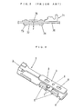
- FIG. 1 For a conventional connection structure of this kind, as shown in FIG. 1 , one configured so that: barrels 51 are formed in an upstanding manner on a lower plate of each of terminal fittings 50 having an upper plate and the lower plate; holes 52 to which the barrels 51 in the lower plate are inserted is formed on a circuit board 53; a reinforcing plate 54 having similar holes is provided on the hole-formed part of the board 53; the upper plate is lifted to insert the barrels 51 formed on the lower plate to the holes 52 of the circuit board 53 and then the upper plate is retuned to its original position, thereby the board 53 being sandwiched between the lower plate and the upper plate and the barrels 51 are bended to secure the upper plate; and the print side of the circuit board 53 and the lower plate are in contact with each other is unknown.
- this conventional art example it is possible to improve workability, prevent a circuit surface from being damaged and enhance connection reliability.
- each of terminals 61 is provided at one end in the longitudinal direction of a base 60; an FPC 62 is mounted on a mounting surface of the base 60; and the FPC 62 is pressure-bonded and secured by the outer peripheral surfaces of barrels 63 and the mounting surface, the barrels 63 extending from both sides of the base 60 substantially perpendicular to the longitudinal direction of the base 60, being provided facing the mounting surface and being curved inward to form a cylindrical shape, is known.
- the outer peripheral surfaces of the barrels 63 are in surface-contact with the FPC 62 and concentrative stress applied to the FPC 62 is thereby relaxed, making it possible to prevent the FPC 62 from being damaged.
- FIG. 3 For a still another conventional art example, as shown in FIG. 3 , one including: a pair of metal plates 71 and 72 holding a membrane circuit 70 therebetween; two connection members 73 and 74 connecting, in a fixed manner, the pair of metal plates 71 and 72 with the membrane circuit 70 interposed therebetween; and at least one protrusion 75 formed on at least one of the pair of metal plates 71 and 72 and located in between the two connection members 73 and 74 in such a manner that it protrudes toward the membrane circuit 70 is known.
- FIG. 1 Since the conventional art example shown in FIG. 1 has a structure in which protrusions are provided only to either the upper plate or the lower plate of each of the terminals to make the circuit of the flexible substrate and the terminals in contact with each other, it lacks connection reliability when surfaces of the terminals with no protrusions and the circuit side are made in contact with each other, and accordingly, it is necessary to turn the terminals around to fit the circuit surface of the flexible substrate.
- the conventional art example shown in FIG. 2 has a disadvantage in that it is difficult to keep the balance of the contact force between the upper portion and the lower portion where a structure in which the upper portion is provided with protrusions and the lower portion is provided with holes is employed, because the contact point shape is different between the upper and lower portions. Where the balance cannot be kept well, a different behavior may occur when an environmental test or the like is conducted.
- an object of the present invention is to provide a structure for connecting a flexible substrate and a terminal fitting, the structure being capable of reliably making a circuit of the flexible substrate and a terminal in contact with each other and conductive to each other regardless of whether the flexible substrate has the circuit on the upper or lower side (connection can be made on either side of the flexible substrate); providing the two-sided connection using a terminal with a conventional shape as it is (only the pressure-bonding portion is changed); making it easier to keep the balance between the contact forces of the upper and lower portions and thereby improving connection reliability; improve workability because terminal pressure-bonding work can be performed without paying attention to on which side the flexible substrate has a circuit, resulting in substantial reduction of the number of man-hours.
- the present invention provides a structure for connecting a flexible substrate and a terminal fitting, the terminal fitting including an upper plate and a lower plate, a barrel being formed in an upstanding manner on the lower plate, a hole to which the barrel on the lower plate is inserted being formed in the flexible substrate, the flexible substrate being held between the upper plate and the lower plate by bending the barrel inserted to the hole, wherein: a projection is formed in each of the upper plate and the lower plate; and the flexible substrate is held between the projections.
- the present invention described above makes it possible to reliably make a circuit of a flexible substrate and a terminal in contact with each other and conductive to each other regardless of whether the flexible substrate has the circuit on the upper or lower side (connection can be made on either side of the flexible substrate), and to provide the two-sided connection using a terminal with a conventional shape as it is (only the pressure-bonding portion is changed). Also, it makes it easier to keep the balance between the contact forces of the upper and lower sides, thereby enhancing connection reliability. Furthermore, it enhances workability because terminal pressure-bonding work can be performed without paying attention to on which side the flexible substrate has the circuit, resulting in substantial reduction of the number of man-hours.
- Another aspect of the present invention provides a structure for connecting a flexible substrate and a terminal fitting, the terminal fitting including an upper plate and a lower plate, a barrel being formed in an upstanding manner on the lower plate, a hole to which the barrel on the lower plate is inserted being formed in the flexible substrate, the flexible substrate being held between the upper plate and the lower plate by bending the barrel inserted to the hole, wherein: the flexible substrate is held between projections formed in the upper plate and the lower plate; a projection in one of the upper plate and the lower plate, the projection being elongated in a width direction of the plate, projects longer than an adjacent projection elongated in a longitudinal direction of the plate; a projection in the other plate, the projection being elongated in a longitudinal direction of the other plate, projects longer than an adjacent projection elongated in a width direction of the other plate; a recess is formed at a back side of each of the projections; a surface of each of the projections is formed to have an elongated flat surface; and when the projection
- the present invention described above makes it possible to reliably make a circuit of a flexible substrate and a terminal in contact with each other and conductive to each other regardless of whether the flexible substrate has the circuit on the upper or lower side (connection can be made on either side of the flexible substrate), and to provide the two-sided connection using a terminal with a conventional shape as it is (only the pressure-bonding portion is changed). Also, it makes it easier to keep the balance between the contact forces of the upper and lower sides, thereby enhancing connection reliability. Furthermore, it enhances workability because terminal pressure-bonding work can be performed without paying attention to on which side the flexible substrate has the circuit, resulting in substantial reduction of the number of man-hours. In particular, the long sides of the projection form edges, and the flexible substrate and these edges are connected by means of large stress, providing reliable electrical and mechanical connection.
- a still another aspect of the present invention provides a structure for connecting a flexible substrate and a terminal fitting, the terminal fitting including an upper plate and a lower plate, a barrel being formed in an upstanding manner on the lower plate, a hole to which the barrel on the lower plate is inserted being formed in the flexible substrate, the flexible substrate being held between the upper plate and the lower plate by bending the barrel inserted to the hole, wherein: the flexible substrate is held between projections formed in the upper plate and the lower plate; a projection in one of the upper plate and the lower plate, the projection being elongated in a width direction of the plate, projects longer than an adjacent projection elongated in a longitudinal direction of the plate; a projection in the other plate, the projection being elongated in a longitudinal direction of the other plate, projects longer than an adjacent projection elongated in a width direction of the other plate; a recess is formed at a back side of each of the projections; when the projections both project longer are brought into contact with the flexible substrate by pressure, a surface of the
- the present invention described above makes it possible to reliably make a circuit of a flexible substrate and a terminal in contact with each other and conductive to each other regardless of whether the flexible substrate has the circuit on the upper or lower side (connection can be made on either side of the flexible substrate), and to provide the two-sided connection using a terminal with a conventional shape as it is (only the pressure-bonding portion is changed). Also, it makes it easier to keep the balance between the contact forces of the upper and lower sides, thereby enhancing connection reliability. Furthermore, it enhances workability because terminal pressure-bonding work can be performed without paying attention to on which side the flexible substrate has the circuit, resulting in substantial reduction of the number of man-hours.
- the surface of the projection elongated in the width direction that projects longer are rounded in a circular arc-like manner, and the rounded portion is made in pressure-contact with the flexible substrate, and accordingly, the flexible substrate is connected by means of large stress without damaging the flexible substrate, which provides reliable electrical and mechanical connection.
- FIGS. 4 to 6 each illustrate a terminal fitting 1 according to a first embodiment, and in the overall perspective view in FIG, 4 , an upper plate 3 and a lower plate 4, which are coupled to a tube 2 to which a male terminal or an electric wire is inserted and secured, extend in parallel to each other, barrels 5 are formed in an upstanding manner on the lower plate 4, projections 6 and 7 are formed on the mutually-facing inner surfaces of the upper plate 3 and the lower plate 4, respectively.
- two barrels 5 is formed
- two projections 7 of the lower plate 4 are formed
- one projection 6 of the upper plate 3 is formed in such a manner that it is positioned between the two projections 7.
- FIG. 6 is a cross-sectional view taken from line A-A in the terminal fitting 1 with the barrels 5 omitted shown in FIG. 5, and FIG. 6 shows that the projection 6 is formed in such a manner that it projects a bit beyond the lower surfaces of the two dents 8 of the upper plate 3.
- FIG. 7 shows a state in which the terminal fitting 1 is connected to a flexible substrate 10 such as an FPC, the barrels 5 formed on the lower plate 4 are inserted to holes 11 formed in the flexible substrate 10, and these barrels 5 are bended inward to draw the upper plate 3 toward the lower plate 4 side in such a manner that they hold the upper plate 3.
- a flexible substrate 10 such as an FPC
- FIG. 8 is a cross-sectional view taken from line B-B of FIG. 7 , and when the flexible substrate 10 is held between the upper plate 3 and the lower plate 4, the flexible substrate 10 is deformed into a wave shape by means of the projections 6 and 7 and the bottoms of the dents 8 are strongly pressed against the flexible substrate 10, as shown in FIG. 6 , the upper plate 3 bends upward as a result of the spring property of the projection 6 portion of the upper plate 3 being exerted because of the level difference. As a result of the bending shown in FIG. 7 , the pressure imposed on the flexible substrate 10 by means of the projection 6 is increased, providing reliable holding.
- a second embodiment which is shown in FIG. 9 , provides an example in which a hard reinforcing plate 12 is provided to a flexible substrate 10 (this is effective especially for an FPC) to connect the flexible substrate 10 and a terminal fitting 1 at the portion where this reinforcing plate 12 is provided.
- the portions of the reinforcing plate 12 corresponding to two projections 7 formed on a lower plate 4 are provided with holes through which the projections 7 pass.
- a projection 6 is positioned at the center of two projections 7, forming a "W-shape" in cross section in FIG. 8 .
- W-shape connection structure it is possible to reliably make the flexible substrate 10 (including a membrane circuit) in contact with and conductive to the terminal fitting 1 regardless of whether the flexible substrate 10 has a circuit on the upper or lower side.
- FIGS. 11 to 14 show a third embodiment that makes it possible to more firmly hold a flexible substrate 10 to strengthen the connection.
- the distance between two projections 7 formed on a lower plate 4 is made to be longer than those of the aforementioned embodiments and a center projection 7A, which is long in the length direction of the lower plate 4, is formed at the portion of the lower plate 4 facing a projection 6 of an upper plate 3 in between the projections 7.
- the other projections 6 and 7 are long in the width direction of the upper and lower plates 3 and 4, and the projection 6 and the center projection 7A form a cross shape when they are overlapped with each other.
- the projections 7 face dents 8, and the projections 7 face dents 8 form a cross shape when they are overlapped with each other.
- a terminal fitting 1 which is shown in FIGS. 15 and 16 , is a fourth embodiment in which an upper plate 3 and a lower plate 4, which are coupled to a tube 2 to which a male terminal or an electric wire is inserted and secured, extend in parallel with each other, barrels 5 are formed in an upstanding manner on the lower plate 4, and projections 13 to 18 are respectively formed on the mutually-facing inner surfaces of the upper plate 3 and the lower plate 4.
- two pairs of barrels 5, each pair consisting of two, i.e., right and left barrels, are formed.
- the projections 13 to 18 consist of: two (projections 13 and 15) with a shape elongated along the longitudinal direction of the upper plate 3 and one (projection 14) with a shape elongated along the width direction in between these projections in the upper plate 3; and two (projections 16 and 18) with a shape elongated along the width direction of the lower plate 4 and one (projection 17) with a shape elongated along the longitudinal direction in between these projections in the lower plate 4.
- the surfaces of these projections 13 to 18 are formed to have elongated plat surfaces, and on the back sides thereof, recesses 13A to 18A are formed. These recesses 13A to 18A are formed at positions where metal plate materials are struck by means of press-molding and the projections 13 to 18 are formed at the portions that have protruded as a result of the pressing.
- FIG. 18 shows a state in which the terminal fitting 1 is connected to a flexible substrate 10 such as an FPC, the barrels 5 formed on the lower plate 4 are inserted to holes H formed in the flexible substrate 10, and these barrels 5 are bended inward to draw the upper plate 3 toward the lower plate 4 side in such a manner that they hold the upper plate 3.
- a flexible substrate 10 such as an FPC
- FIG. 19 is a cross-sectional view taken from line B-B of FIG. 18 , and when the flexible substrate 10 is held between the upper plate 3 and the lower plate 4, the flexible substrate 10 is deformed into a wave shape by means of the projections 14 and 17 and the bottoms of the recesses 13A and 15A are strongly pressed against the flexible substrate 10, as shown in FIG. 17 , the upper plate 3 bends upward as a result of the spring property of the projection 14 portion of the upper plate 3 being exerted because of the level difference. As a result of the bending shown in FIG. 19 , the pressure imposed on the flexible substrate 10 by means of the projection 14 is increased, providing reliable holding.
- FIG. 20 is an enlarged view of a part of the projection 14 in a pressure-contact state, and shows the state of two long sides x and an intermediate portion y in between these long sides x of the elongated projection 14.
- the long sides upon being made into pressure-contact and the intermediate portion y denting, act as edges (x), and these edges (x) are in strong-contact with the flexible substrate 10.
- a terminal fitting which is shown in FIGS. 20 to 24 , is a fifth embodiment in which an upper plate 3 and a lower plate 4, which are coupled to a tube 2 to which a male terminal or an electric wire is inserted and secured, extend in parallel with each other, barrels 5 are formed in an upstanding manner on the lower plate 4, and projections 13 to 18 are respectively formed on the mutually-facing inner surfaces of the upper plate 3 and the lower plate 4.
- two pairs of barrels 5, each pair consisting of two, i.e., right and left barrels, are formed.
- the projections 13 to 18 consist of: two (projections 13 and 15) with a shape elongated along the longitudinal direction of the upper plate 3 and one (projection 14) with a shape elongated along the width direction in between these projections in the upper plate 3; and two (projections 16 and 18) with a shape elongated along the width direction of the lower plate 4 and one (projection 17) with a shape elongated along the longitudinal direction in between these projections in the lower plate 4.
- the surfaces of these projections 13 to 18 are formed to have elongated plat surfaces, and on the back sides thereof, recesses 13A to 18A are formed. These recesses 13A to 18A are formed at positions where metal plate materials are struck by means of press-molding and the projections 13 to 18 are formed at the portions that have protruded as a result of the pressing.
- FIG. 24 shows a state in which the terminal fitting 1 is connected to a flexible substrate 10 such as an FPC, the barrels 5 formed on the lower plate 4 are inserted to holes H formed in the flexible substrate 10, and these barrels 5 are bended inward to draw the upper plate 3 toward the lower plate 4 side in such a manner that they hold the upper plate 3.
- a flexible substrate 10 such as an FPC
- FIG. 25 is a cross-sectional view taken from line B-B of FIG. 24 , and when the flexible substrate 10 is held between the upper plate 3 and the lower plate 4, the flexible substrate 10 is deformed into a wave shape by means of the projections 14 and 17 and the bottoms of the recesses 13A and 15A are strongly pressed against the flexible substrate 10, as shown in FIG. 23 , the upper plate 3 bends upward as a result of the spring property of the projection 14 portion of the upper plate 3 being exerted because of the level difference. As a result of the bending shown in FIG. 25 , the pressure imposed on the flexible substrate 10 by means of the projection 14 is increased, providing reliable holding.
- FIG. 26 is an enlarged diagram showing the shape of the surface of the projection 14 formed in the center of the upper plate 3, which projects in a shape rounded in a circular arc-like manner.
- FIG. 27 shows the shape when the rounded surface shape comes into pressure-contact with the flexible substrate 10: the pressure-contact portion remains rounded so that it is not in pressure-contact with the flexible substrate 10, with a sharpened shape.
Landscapes
- Coupling Device And Connection With Printed Circuit (AREA)
- Multi-Conductor Connections (AREA)
Abstract
Description
- The present invention relates to a structure for connecting a flexible substrate, such as a membrane board or a flexible printed circuit board (FPC), and a terminal fitting.
- For a conventional connection structure of this kind, as shown in
FIG. 1 , one configured so that:barrels 51 are formed in an upstanding manner on a lower plate of each ofterminal fittings 50 having an upper plate and the lower plate;holes 52 to which thebarrels 51 in the lower plate are inserted is formed on acircuit board 53; a reinforcingplate 54 having similar holes is provided on the hole-formed part of theboard 53; the upper plate is lifted to insert thebarrels 51 formed on the lower plate to theholes 52 of thecircuit board 53 and then the upper plate is retuned to its original position, thereby theboard 53 being sandwiched between the lower plate and the upper plate and thebarrels 51 are bended to secure the upper plate; and the print side of thecircuit board 53 and the lower plate are in contact with each other is unknown. According to this conventional art example, it is possible to improve workability, prevent a circuit surface from being damaged and enhance connection reliability. - For another conventional art example, as shown in
FIG. 2 , one configured so that: each ofterminals 61 is provided at one end in the longitudinal direction of abase 60; an FPC 62 is mounted on a mounting surface of thebase 60; and the FPC 62 is pressure-bonded and secured by the outer peripheral surfaces ofbarrels 63 and the mounting surface, thebarrels 63 extending from both sides of thebase 60 substantially perpendicular to the longitudinal direction of thebase 60, being provided facing the mounting surface and being curved inward to form a cylindrical shape, is known. With this configuration, the outer peripheral surfaces of thebarrels 63 are in surface-contact with theFPC 62 and concentrative stress applied to the FPC 62 is thereby relaxed, making it possible to prevent the FPC 62 from being damaged. Even though the material thickness of the FPC 62 is decreased as a result of the relaxation of stress on the FPC 62 due to secular changes, an elastic force can be applied to the FPC 62 by thebarrels 63, making it possible to maintain stable connection to the FPC 62 over a long period of time. Thesebarrels 63 have a small spring constant, and accordingly, it can reduce an elastic pressure decrease caused by the decease of the material thickness of the FPC 62. - For a still another conventional art example, as shown in
FIG. 3 , one including: a pair ofmetal plates membrane circuit 70 therebetween; twoconnection members metal plates membrane circuit 70 interposed therebetween; and at least oneprotrusion 75 formed on at least one of the pair ofmetal plates connection members membrane circuit 70 is known. - Since the conventional art example shown in
FIG. 1 has a structure in which protrusions are provided only to either the upper plate or the lower plate of each of the terminals to make the circuit of the flexible substrate and the terminals in contact with each other, it lacks connection reliability when surfaces of the terminals with no protrusions and the circuit side are made in contact with each other, and accordingly, it is necessary to turn the terminals around to fit the circuit surface of the flexible substrate. - The conventional art example shown in
FIG. 2 has a disadvantage in that it is difficult to keep the balance of the contact force between the upper portion and the lower portion where a structure in which the upper portion is provided with protrusions and the lower portion is provided with holes is employed, because the contact point shape is different between the upper and lower portions. Where the balance cannot be kept well, a different behavior may occur when an environmental test or the like is conducted. - The conventional art example shown in
FIG. 3 , the protrusion of the terminal and the circuit surface of the flexible substrate are made in contact with each other after they are matched with each other, which results in poor workability. Also, with this conventional art example structure, it is difficult to employ multipolarity. - Accordingly, an object of the present invention is to provide a structure for connecting a flexible substrate and a terminal fitting, the structure being capable of reliably making a circuit of the flexible substrate and a terminal in contact with each other and conductive to each other regardless of whether the flexible substrate has the circuit on the upper or lower side (connection can be made on either side of the flexible substrate); providing the two-sided connection using a terminal with a conventional shape as it is (only the pressure-bonding portion is changed); making it easier to keep the balance between the contact forces of the upper and lower portions and thereby improving connection reliability; improve workability because terminal pressure-bonding work can be performed without paying attention to on which side the flexible substrate has a circuit, resulting in substantial reduction of the number of man-hours.
- In order to achieve the above object, the present invention provides a structure for connecting a flexible substrate and a terminal fitting, the terminal fitting including an upper plate and a lower plate, a barrel being formed in an upstanding manner on the lower plate, a hole to which the barrel on the lower plate is inserted being formed in the flexible substrate, the flexible substrate being held between the upper plate and the lower plate by bending the barrel inserted to the hole, wherein: a projection is formed in each of the upper plate and the lower plate; and the flexible substrate is held between the projections.
- The present invention described above makes it possible to reliably make a circuit of a flexible substrate and a terminal in contact with each other and conductive to each other regardless of whether the flexible substrate has the circuit on the upper or lower side (connection can be made on either side of the flexible substrate), and to provide the two-sided connection using a terminal with a conventional shape as it is (only the pressure-bonding portion is changed). Also, it makes it easier to keep the balance between the contact forces of the upper and lower sides, thereby enhancing connection reliability. Furthermore, it enhances workability because terminal pressure-bonding work can be performed without paying attention to on which side the flexible substrate has the circuit, resulting in substantial reduction of the number of man-hours.
- Another aspect of the present invention provides a structure for connecting a flexible substrate and a terminal fitting, the terminal fitting including an upper plate and a lower plate, a barrel being formed in an upstanding manner on the lower plate, a hole to which the barrel on the lower plate is inserted being formed in the flexible substrate, the flexible substrate being held between the upper plate and the lower plate by bending the barrel inserted to the hole, wherein: the flexible substrate is held between projections formed in the upper plate and the lower plate; a projection in one of the upper plate and the lower plate, the projection being elongated in a width direction of the plate, projects longer than an adjacent projection elongated in a longitudinal direction of the plate; a projection in the other plate, the projection being elongated in a longitudinal direction of the other plate, projects longer than an adjacent projection elongated in a width direction of the other plate; a recess is formed at a back side of each of the projections; a surface of each of the projections is formed to have an elongated flat surface; and when the projections both project longer are brought into contact with the flexible substrate by pressure, an intermediate portion between two long sides of the projection elongated in the width direction dents, thereby the two long sides coming into pressure-contact with the flexible substrate as edges.
- The present invention described above makes it possible to reliably make a circuit of a flexible substrate and a terminal in contact with each other and conductive to each other regardless of whether the flexible substrate has the circuit on the upper or lower side (connection can be made on either side of the flexible substrate), and to provide the two-sided connection using a terminal with a conventional shape as it is (only the pressure-bonding portion is changed). Also, it makes it easier to keep the balance between the contact forces of the upper and lower sides, thereby enhancing connection reliability. Furthermore, it enhances workability because terminal pressure-bonding work can be performed without paying attention to on which side the flexible substrate has the circuit, resulting in substantial reduction of the number of man-hours. In particular, the long sides of the projection form edges, and the flexible substrate and these edges are connected by means of large stress, providing reliable electrical and mechanical connection.
- A still another aspect of the present invention provides a structure for connecting a flexible substrate and a terminal fitting, the terminal fitting including an upper plate and a lower plate, a barrel being formed in an upstanding manner on the lower plate, a hole to which the barrel on the lower plate is inserted being formed in the flexible substrate, the flexible substrate being held between the upper plate and the lower plate by bending the barrel inserted to the hole, wherein: the flexible substrate is held between projections formed in the upper plate and the lower plate; a projection in one of the upper plate and the lower plate, the projection being elongated in a width direction of the plate, projects longer than an adjacent projection elongated in a longitudinal direction of the plate; a projection in the other plate, the projection being elongated in a longitudinal direction of the other plate, projects longer than an adjacent projection elongated in a width direction of the other plate; a recess is formed at a back side of each of the projections; when the projections both project longer are brought into contact with the flexible substrate by pressure, a surface of the projection elongated in the width direction comes into pressure-contact with the flexible substrate, in a shape rounded in an circular arc-like manner; and a surface of the facing projection elongated in the longitudinal direction is formed to have a flat surface.
- The present invention described above makes it possible to reliably make a circuit of a flexible substrate and a terminal in contact with each other and conductive to each other regardless of whether the flexible substrate has the circuit on the upper or lower side (connection can be made on either side of the flexible substrate), and to provide the two-sided connection using a terminal with a conventional shape as it is (only the pressure-bonding portion is changed). Also, it makes it easier to keep the balance between the contact forces of the upper and lower sides, thereby enhancing connection reliability. Furthermore, it enhances workability because terminal pressure-bonding work can be performed without paying attention to on which side the flexible substrate has the circuit, resulting in substantial reduction of the number of man-hours. In particular, the surface of the projection elongated in the width direction that projects longer are rounded in a circular arc-like manner, and the rounded portion is made in pressure-contact with the flexible substrate, and accordingly, the flexible substrate is connected by means of large stress without damaging the flexible substrate, which provides reliable electrical and mechanical connection.
-
-
FIG. 1 is a perspective view of a conventional art example; -
FIG. 2 is a perspective view of another conventional art example; -
FIG. 3 is a perspective view of a still another conventional art example; -
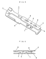
FIG. 4 is a perspective view of a terminal fitting according to a first embodiment of the present invention; -
FIG. 5 is a perspective view of the terminal fitting shown inFIG. 4 with barrels omitted; -
FIG. 6 is a cross-sectional view taken from line A-A ofFIG. 5 ; -
FIG. 7 is a perspective diagram showing a state of connection; -
FIG. 8 is a cross-sectional view taken from line B-B ofFIG. 7 ; -
FIG. 9 is a perspective view of a second embodiment viewed from the back surface side; -
FIG. 10 is a perspective view of a terminal fitting according to a third embodiment; -
FIG. 11 is a perspective view of the terminal fitting shown inFIG. 10 with the barrels omitted; -
FIG. 12 is a perspective diagram showing a state of connection; -
FIG. 13 is a cross-sectional view taken from line C-C ofFIG. 11 ; -
FIG. 14 is a cross-sectional view taken from line D-D ofFIG. 12 ; -
FIG. 15 is a perspective view of a terminal fitting according to a fourth embodiment; -
FIG. 16 is a perspective view of the terminal fitting shown inFIG. 15 with the barrels omitted; -
FIG. 17 is a cross-sectional view taken from line A-A ofFIG. 16 ; -
FIG. 18 is a perspective diagram showing a state of connection; -
FIG. 19 is a cross-sectional view taken from line B-B ofFIG. 18 ; -
FIG. 20 is an enlarged view of a projection tip; -
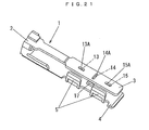
FIG. 21 is a perspective view of a terminal fitting according to a fifth embodiment; -
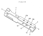
FIG. 22 is a perspective view of the terminal fitting shown inFIG. 21 with the barrels omitted; -
FIG. 23 is a cross-sectional view taken from line A-A ofFIG. 22 ; -
FIG. 24 is a perspective diagram showing a state of connection; -
FIG. 25 is a cross-sectional view taken from line B-B ofFIG. 23 ; -
FIG. 26 is an enlarged view of a projection tip; and -
FIG. 27 is an enlarged view of a projection tip in a pressure-contact state. -
FIGS. 4 to 6 each illustrate aterminal fitting 1 according to a first embodiment, and in the overall perspective view inFIG, 4 , anupper plate 3 and alower plate 4, which are coupled to atube 2 to which a male terminal or an electric wire is inserted and secured, extend in parallel to each other,barrels 5 are formed in an upstanding manner on thelower plate 4,projections upper plate 3 and thelower plate 4, respectively. In the Figure, twobarrels 5 is formed, twoprojections 7 of thelower plate 4 are formed, and oneprojection 6 of theupper plate 3 is formed in such a manner that it is positioned between the twoprojections 7. Also, in order to provide this projection 6-formed portion of theupper plate 3 with a spring property,dents 8 are formed on both sides of theprojection 6. Also,FIG. 6 is a cross-sectional view taken from line A-A in the terminal fitting 1 with thebarrels 5 omitted shown inFIG. 5, and FIG. 6 shows that theprojection 6 is formed in such a manner that it projects a bit beyond the lower surfaces of the twodents 8 of theupper plate 3. -
FIG. 7 shows a state in which theterminal fitting 1 is connected to aflexible substrate 10 such as an FPC, thebarrels 5 formed on thelower plate 4 are inserted toholes 11 formed in theflexible substrate 10, and thesebarrels 5 are bended inward to draw theupper plate 3 toward thelower plate 4 side in such a manner that they hold theupper plate 3. -
FIG. 8 is a cross-sectional view taken from line B-B ofFIG. 7 , and when theflexible substrate 10 is held between theupper plate 3 and thelower plate 4, theflexible substrate 10 is deformed into a wave shape by means of theprojections dents 8 are strongly pressed against theflexible substrate 10, as shown inFIG. 6 , theupper plate 3 bends upward as a result of the spring property of theprojection 6 portion of theupper plate 3 being exerted because of the level difference. As a result of the bending shown inFIG. 7 , the pressure imposed on theflexible substrate 10 by means of theprojection 6 is increased, providing reliable holding. - A second embodiment, which is shown in
FIG. 9 , provides an example in which a hard reinforcingplate 12 is provided to a flexible substrate 10 (this is effective especially for an FPC) to connect theflexible substrate 10 and aterminal fitting 1 at the portion where this reinforcingplate 12 is provided. The portions of the reinforcingplate 12 corresponding to twoprojections 7 formed on alower plate 4 are provided with holes through which theprojections 7 pass. - Three
projections lower plates 3 and 4: aprojection 6 is positioned at the center of twoprojections 7, forming a "W-shape" in cross section inFIG. 8 . With such W-shape connection structure, it is possible to reliably make the flexible substrate 10 (including a membrane circuit) in contact with and conductive to theterminal fitting 1 regardless of whether theflexible substrate 10 has a circuit on the upper or lower side. -
FIGS. 11 to 14 show a third embodiment that makes it possible to more firmly hold aflexible substrate 10 to strengthen the connection. In other words, the distance between twoprojections 7 formed on alower plate 4 is made to be longer than those of the aforementioned embodiments and acenter projection 7A, which is long in the length direction of thelower plate 4, is formed at the portion of thelower plate 4 facing aprojection 6 of anupper plate 3 in between theprojections 7. Theother projections lower plates projection 6 and thecenter projection 7A form a cross shape when they are overlapped with each other. Also, theprojections 7 face dents 8, and theprojections 7 face dents 8 form a cross shape when they are overlapped with each other. - A
terminal fitting 1, which is shown inFIGS. 15 and16 , is a fourth embodiment in which anupper plate 3 and alower plate 4, which are coupled to atube 2 to which a male terminal or an electric wire is inserted and secured, extend in parallel with each other,barrels 5 are formed in an upstanding manner on thelower plate 4, andprojections 13 to 18 are respectively formed on the mutually-facing inner surfaces of theupper plate 3 and thelower plate 4. As shown, two pairs ofbarrels 5, each pair consisting of two, i.e., right and left barrels, are formed. Theprojections 13 to 18 consist of: two (projections 13 and 15) with a shape elongated along the longitudinal direction of theupper plate 3 and one (projection 14) with a shape elongated along the width direction in between these projections in theupper plate 3; and two (projections 16 and 18) with a shape elongated along the width direction of thelower plate 4 and one (projection 17) with a shape elongated along the longitudinal direction in between these projections in thelower plate 4. Then, the surfaces of theseprojections 13 to 18 are formed to have elongated plat surfaces, and on the back sides thereof, recesses 13A to 18A are formed. Theserecesses 13A to 18A are formed at positions where metal plate materials are struck by means of press-molding and theprojections 13 to 18 are formed at the portions that have protruded as a result of the pressing. - The
projection 14, which is positioned in the middle of theupper plate 3 and elongated in the width direction of theupper plate 3, as shown inFIG. 17 , projects longer than theprojections projection 14 and elongated in the longitudinal direction (in the Figure, it projects longer downward), and theprojection 17, which is positioned in the middle of thelower plate 4 and elongated in the longitudinal direction of thelower plate 4, projects longer than theprojections projection 17 and elongated in the width direction (in the Figure, it projects longer upward). -
FIG. 18 shows a state in which the terminal fitting 1 is connected to aflexible substrate 10 such as an FPC, thebarrels 5 formed on thelower plate 4 are inserted to holes H formed in theflexible substrate 10, and thesebarrels 5 are bended inward to draw theupper plate 3 toward thelower plate 4 side in such a manner that they hold theupper plate 3. -
FIG. 19 is a cross-sectional view taken from line B-B ofFIG. 18 , and when theflexible substrate 10 is held between theupper plate 3 and thelower plate 4, theflexible substrate 10 is deformed into a wave shape by means of theprojections recesses flexible substrate 10, as shown inFIG. 17 , theupper plate 3 bends upward as a result of the spring property of theprojection 14 portion of theupper plate 3 being exerted because of the level difference. As a result of the bending shown inFIG. 19 , the pressure imposed on theflexible substrate 10 by means of theprojection 14 is increased, providing reliable holding. -
FIG. 20 is an enlarged view of a part of theprojection 14 in a pressure-contact state, and shows the state of two long sides x and an intermediate portion y in between these long sides x of theelongated projection 14. The long sides, upon being made into pressure-contact and the intermediate portion y denting, act as edges (x), and these edges (x) are in strong-contact with theflexible substrate 10. - A terminal fitting, which is shown in
FIGS. 20 to 24 , is a fifth embodiment in which anupper plate 3 and alower plate 4, which are coupled to atube 2 to which a male terminal or an electric wire is inserted and secured, extend in parallel with each other,barrels 5 are formed in an upstanding manner on thelower plate 4, andprojections 13 to 18 are respectively formed on the mutually-facing inner surfaces of theupper plate 3 and thelower plate 4. As shown, two pairs ofbarrels 5, each pair consisting of two, i.e., right and left barrels, are formed. Theprojections 13 to 18 consist of: two (projections 13 and 15) with a shape elongated along the longitudinal direction of theupper plate 3 and one (projection 14) with a shape elongated along the width direction in between these projections in theupper plate 3; and two (projections 16 and 18) with a shape elongated along the width direction of thelower plate 4 and one (projection 17) with a shape elongated along the longitudinal direction in between these projections in thelower plate 4. Then, the surfaces of theseprojections 13 to 18 are formed to have elongated plat surfaces, and on the back sides thereof, recesses 13A to 18A are formed. Theserecesses 13A to 18A are formed at positions where metal plate materials are struck by means of press-molding and theprojections 13 to 18 are formed at the portions that have protruded as a result of the pressing. - The
projection 14, which is positioned in the middle of theupper plate 3 and elongated in the width direction of theupper plate 3, as shown inFIG. 23 , projects longer than theprojections projection 14 and elongated in the longitudinal direction (in the Figure, it projects longer downward), and theprojection 17, which is positioned in the middle of thelower plate 4 and elongated in the longitudinal direction of thelower plate 4, projects longer than theprojections projection 17 and elongated in the width direction (in the Figure, it projects longer upward). -
FIG. 24 shows a state in which the terminal fitting 1 is connected to aflexible substrate 10 such as an FPC, thebarrels 5 formed on thelower plate 4 are inserted to holes H formed in theflexible substrate 10, and thesebarrels 5 are bended inward to draw theupper plate 3 toward thelower plate 4 side in such a manner that they hold theupper plate 3. -
FIG. 25 is a cross-sectional view taken from line B-B ofFIG. 24 , and when theflexible substrate 10 is held between theupper plate 3 and thelower plate 4, theflexible substrate 10 is deformed into a wave shape by means of theprojections recesses flexible substrate 10, as shown inFIG. 23 , theupper plate 3 bends upward as a result of the spring property of theprojection 14 portion of theupper plate 3 being exerted because of the level difference. As a result of the bending shown inFIG. 25 , the pressure imposed on theflexible substrate 10 by means of theprojection 14 is increased, providing reliable holding. -
FIG. 26 is an enlarged diagram showing the shape of the surface of theprojection 14 formed in the center of theupper plate 3, which projects in a shape rounded in a circular arc-like manner.FIG. 27 shows the shape when the rounded surface shape comes into pressure-contact with the flexible substrate 10: the pressure-contact portion remains rounded so that it is not in pressure-contact with theflexible substrate 10, with a sharpened shape.
Claims (5)
- A structure for connecting a flexible substrate and a terminal fitting, the terminal fitting including an upper plate and a lower plate, a barrel being formed in an upstanding manner on the lower plate, a hole to which the barrel on the lower plate is inserted being formed in the flexible substrate, the flexible substrate being held between the upper plate and the lower plate by bending the barrel inserted to the hole,
characterized in
that a projection is formed in each of the upper plate and the lower plate; andthat the flexible substrate is held between the projections. - The structure for connecting a flexible substrate and a terminal fitting according to claim 1, characterized in that two projections are formed in the lower plate, one projection located in the middle between the projections is formed in the upper plate, a part of the upper plate in which the projection is formed bends and have a spring property to press the flexible substrate via the projection.
- The structure for connecting a flexible substrate and a terminal fitting according to claim 1 or 2, characterized in that a reinforcing plate is provided to one surface of the flexible substrate held by the terminal fitting.
- A structure for connecting a flexible substrate and a terminal fitting, the terminal fitting including an upper plate and a lower plate, a barrel being formed in an upstanding manner on the lower plate, a hole to which the barrel on the lower plate is inserted being formed in the flexible substrate, the flexible substrate being held between the upper plate and the lower plate by bending the barrel inserted to the hole,
characterized inthat the flexible substrate is held between projections formed in the upper plate and the lower plate;that a projection in one of the upper plate and the lower plate, the projection being elongated in a width direction of the plate, projects longer than an adjacent projection elongated in a longitudinal direction of the plate;that a projection in the other plate, the projection being elongated in a longitudinal direction of the other plate, projects longer than an adjacent projection elongated in a width direction of the other plate;that a recess is formed at a back side of each of the projections;that a surface of each of the projections is formed to have an elongated flat surface; andthat when the projections both project longer are brought into contact with the flexible substrate by pressure, an intermediate portion between two long sides of the projection elongated in the width direction dents, thereby the two long sides coming into pressure-contact with the flexible substrate as edges. - A structure for connecting a flexible substrate and a terminal fitting, the terminal fitting including an upper plate and a lower plate, a barrel being formed in an upstanding manner on the lower plate, a hole to which the barrel on the lower plate is inserted being formed in the flexible substrate, the flexible substrate being held between the upper plate and the lower plate by bending the barrel inserted to the hole,
characterized inthat the flexible substrate is held between projections formed in the upper plate and the lower plate;that a projection in one of the upper plate and the lower plate, the projection being elongated in a width direction of the plate, projects longer than an adjacent projection elongated in a longitudinal direction of the plate;that a projection in the other plate, the projection being elongated in a longitudinal direction of the other plate, projects longer than an adjacent projection elongated in a width direction of the other plate;that a recess is formed at a back side of each of the projections;that when the projections both project longer are brought into contact with the flexible substrate by pressure, a surface of the projection elongated in the width direction comes into pressure-contact with the flexible substrate, in a shape rounded in an circular arc-like manner; andthat a surface of the facing projection elongated in the longitudinal direction is formed to have a flat surface.
Applications Claiming Priority (2)
| Application Number | Priority Date | Filing Date | Title |
|---|---|---|---|
| JP2007261831A JP4914798B2 (en) | 2007-10-05 | 2007-10-05 | Connection structure between flexible board and terminal bracket |
| JP2007261830A JP4914797B2 (en) | 2007-10-05 | 2007-10-05 | Connection structure between flexible board and terminal bracket |
Publications (2)
| Publication Number | Publication Date |
|---|---|
| EP2051334A2 true EP2051334A2 (en) | 2009-04-22 |
| EP2051334A3 EP2051334A3 (en) | 2010-02-24 |
Family
ID=40266023
Family Applications (1)
| Application Number | Title | Priority Date | Filing Date |
|---|---|---|---|
| EP08016675A Withdrawn EP2051334A3 (en) | 2007-10-05 | 2008-10-01 | Structure for connecting flexible substrate and terminal fitting |
Country Status (4)
| Country | Link |
|---|---|
| US (1) | US7980884B2 (en) |
| EP (1) | EP2051334A3 (en) |
| KR (1) | KR101510768B1 (en) |
| CA (1) | CA2645649C (en) |
Families Citing this family (4)
| Publication number | Priority date | Publication date | Assignee | Title |
|---|---|---|---|---|
| JP2011096452A (en) * | 2009-10-28 | 2011-05-12 | Yazaki Corp | Crimping terminal |
| JP5824369B2 (en) | 2012-01-18 | 2015-11-25 | 矢崎総業株式会社 | Connection structure and connection method between flat circuit body and terminal fitting |
| US11296441B2 (en) * | 2020-07-02 | 2022-04-05 | TE Connectivity Services Gmbh | Electrical terminal for flat flexible cables |
| US11296440B2 (en) * | 2020-07-02 | 2022-04-05 | TE Connectivity Services Gmbh | Electrical terminal for flat flexible cables |
Family Cites Families (8)
| Publication number | Priority date | Publication date | Assignee | Title |
|---|---|---|---|---|
| JPH0754720B2 (en) | 1987-04-10 | 1995-06-07 | Electrical connection terminals for flexible printed circuit boards | |
| JPH03271925A (en) | 1990-03-20 | 1991-12-03 | Fujitsu Ltd | Memory disk device |
| US5450664A (en) * | 1993-11-18 | 1995-09-19 | The Whitaker Corporation | Electrical connector for mid-cable termination |
| JPH10271925A (en) | 1997-03-28 | 1998-10-13 | Hiroshi Goto | Hydroponic apparatus |
| JPH11195445A (en) | 1997-12-26 | 1999-07-21 | Amp Japan Ltd | Electric contact for flexible flat cable |
| JP3121591B1 (en) | 1999-08-04 | 2001-01-09 | 株式会社フジクラ | connector |
| WO2004084353A1 (en) * | 2003-03-17 | 2004-09-30 | Lear Corporation | Electric contact element for a flat conductor |
| JP2006172751A (en) | 2004-12-13 | 2006-06-29 | Fujikura Ltd | Connection structure between circuit board and terminal bracket |
-
2008
- 2008-09-29 CA CA2645649A patent/CA2645649C/en not_active Expired - Fee Related
- 2008-09-29 KR KR20080095069A patent/KR101510768B1/en not_active Expired - Fee Related
- 2008-10-01 EP EP08016675A patent/EP2051334A3/en not_active Withdrawn
- 2008-10-03 US US12/245,488 patent/US7980884B2/en not_active Expired - Fee Related
Also Published As
| Publication number | Publication date |
|---|---|
| US7980884B2 (en) | 2011-07-19 |
| CA2645649A1 (en) | 2009-04-05 |
| KR101510768B1 (en) | 2015-04-10 |
| CA2645649C (en) | 2013-10-29 |
| US20090098752A1 (en) | 2009-04-16 |
| KR20090035423A (en) | 2009-04-09 |
| EP2051334A3 (en) | 2010-02-24 |
Similar Documents
| Publication | Publication Date | Title |
|---|---|---|
| CN101030681B (en) | Electric connector for parallel circuit board | |
| US8092232B2 (en) | Board-to-board connector | |
| US20120009828A1 (en) | Terminal fitting and a method for assembling the same | |
| KR101539873B1 (en) | Board connecting terminal | |
| JP4914797B2 (en) | Connection structure between flexible board and terminal bracket | |
| JP4889027B2 (en) | Connection structure between flexible board and terminal bracket | |
| US9306381B2 (en) | Electrical device having busbar with flexible weld crimp | |
| CN102195154A (en) | Press-fit terminal | |
| CA2645649C (en) | Structure for connecting flexible substrate and terminal fitting | |
| CN108511935B (en) | Double-side contact spring sheet | |
| CN103444001B (en) | Electric plug connector | |
| US8747139B2 (en) | Auxiliary fitting having a laminate terminal fitting with an assembling portion having interlocking portions | |
| JP5465579B2 (en) | Crimp terminal | |
| JP4914798B2 (en) | Connection structure between flexible board and terminal bracket | |
| CN207491412U (en) | a mobile terminal | |
| HK1131842A (en) | Structure for connecting flexible substrate and terminal fitting | |
| CN102025041B (en) | Connecting terminal, switching device using same and manufacturing method of connecting terminal | |
| JP2006172751A (en) | Connection structure between circuit board and terminal bracket | |
| CN112362914A (en) | Flexible circuit board for testing and compression joint testing method | |
| CN112005449A (en) | Connector | |
| CN100438216C (en) | Connector | |
| JP5465577B2 (en) | Crimp terminal | |
| CN108551015B (en) | Connector terminal | |
| CN102013592B (en) | Connection terminal and AC adapter | |
| HK1128558A (en) | Structure for connecting flexible substrate and terminal fitting |
Legal Events
| Date | Code | Title | Description |
|---|---|---|---|
| PUAI | Public reference made under article 153(3) epc to a published international application that has entered the european phase |
Free format text: ORIGINAL CODE: 0009012 |
|
| AK | Designated contracting states |
Kind code of ref document: A2 Designated state(s): AT BE BG CH CY CZ DE DK EE ES FI FR GB GR HR HU IE IS IT LI LT LU LV MC MT NL NO PL PT RO SE SI SK TR |
|
| AX | Request for extension of the european patent |
Extension state: AL BA MK RS |
|
| PUAL | Search report despatched |
Free format text: ORIGINAL CODE: 0009013 |
|
| REG | Reference to a national code |
Ref country code: HK Ref legal event code: DE Ref document number: 1131842 Country of ref document: HK |
|
| AK | Designated contracting states |
Kind code of ref document: A3 Designated state(s): AT BE BG CH CY CZ DE DK EE ES FI FR GB GR HR HU IE IS IT LI LT LU LV MC MT NL NO PL PT RO SE SI SK TR |
|
| AX | Request for extension of the european patent |
Extension state: AL BA MK RS |
|
| 17P | Request for examination filed |
Effective date: 20100818 |
|
| 17Q | First examination report despatched |
Effective date: 20100924 |
|
| AKX | Designation fees paid |
Designated state(s): AT BE BG CH CY CZ DE DK EE ES FI FR GB GR HR HU IE IS IT LI LT LU LV MC MT NL NO PL PT RO SE SI SK TR |
|
| REG | Reference to a national code |
Ref country code: HK Ref legal event code: WD Ref document number: 1131842 Country of ref document: HK |
|
| STAA | Information on the status of an ep patent application or granted ep patent |
Free format text: STATUS: THE APPLICATION IS DEEMED TO BE WITHDRAWN |
|
| 18D | Application deemed to be withdrawn |
Effective date: 20160503 |