EP2051154A1 - Dispositif électronique incluant un dispositif électronique portable doté d'un étui intelligent - Google Patents
Dispositif électronique incluant un dispositif électronique portable doté d'un étui intelligent Download PDFInfo
- Publication number
- EP2051154A1 EP2051154A1 EP07118415A EP07118415A EP2051154A1 EP 2051154 A1 EP2051154 A1 EP 2051154A1 EP 07118415 A EP07118415 A EP 07118415A EP 07118415 A EP07118415 A EP 07118415A EP 2051154 A1 EP2051154 A1 EP 2051154A1
- Authority
- EP
- European Patent Office
- Prior art keywords
- electronic device
- handheld electronic
- holster
- battery
- notification
- Prior art date
- Legal status (The legal status is an assumption and is not a legal conclusion. Google has not performed a legal analysis and makes no representation as to the accuracy of the status listed.)
- Ceased
Links
Images


Classifications
-
- G—PHYSICS
- G06—COMPUTING; CALCULATING OR COUNTING
- G06F—ELECTRIC DIGITAL DATA PROCESSING
- G06F1/00—Details not covered by groups G06F3/00 - G06F13/00 and G06F21/00
- G06F1/16—Constructional details or arrangements
- G06F1/1613—Constructional details or arrangements for portable computers
- G06F1/1632—External expansion units, e.g. docking stations
-
- G—PHYSICS
- G06—COMPUTING; CALCULATING OR COUNTING
- G06F—ELECTRIC DIGITAL DATA PROCESSING
- G06F1/00—Details not covered by groups G06F3/00 - G06F13/00 and G06F21/00
- G06F1/16—Constructional details or arrangements
- G06F1/1613—Constructional details or arrangements for portable computers
- G06F1/1626—Constructional details or arrangements for portable computers with a single-body enclosure integrating a flat display, e.g. Personal Digital Assistants [PDAs]
-
- G—PHYSICS
- G06—COMPUTING; CALCULATING OR COUNTING
- G06F—ELECTRIC DIGITAL DATA PROCESSING
- G06F1/00—Details not covered by groups G06F3/00 - G06F13/00 and G06F21/00
- G06F1/16—Constructional details or arrangements
- G06F1/1613—Constructional details or arrangements for portable computers
- G06F1/1633—Constructional details or arrangements of portable computers not specific to the type of enclosures covered by groups G06F1/1615 - G06F1/1626
- G06F1/1684—Constructional details or arrangements related to integrated I/O peripherals not covered by groups G06F1/1635 - G06F1/1675
-
- H—ELECTRICITY
- H02—GENERATION; CONVERSION OR DISTRIBUTION OF ELECTRIC POWER
- H02J—CIRCUIT ARRANGEMENTS OR SYSTEMS FOR SUPPLYING OR DISTRIBUTING ELECTRIC POWER; SYSTEMS FOR STORING ELECTRIC ENERGY
- H02J7/00—Circuit arrangements for charging or depolarising batteries or for supplying loads from batteries
- H02J7/0029—Circuit arrangements for charging or depolarising batteries or for supplying loads from batteries with safety or protection devices or circuits
- H02J7/00302—Overcharge protection
-
- H—ELECTRICITY
- H02—GENERATION; CONVERSION OR DISTRIBUTION OF ELECTRIC POWER
- H02J—CIRCUIT ARRANGEMENTS OR SYSTEMS FOR SUPPLYING OR DISTRIBUTING ELECTRIC POWER; SYSTEMS FOR STORING ELECTRIC ENERGY
- H02J7/00—Circuit arrangements for charging or depolarising batteries or for supplying loads from batteries
- H02J7/0029—Circuit arrangements for charging or depolarising batteries or for supplying loads from batteries with safety or protection devices or circuits
- H02J7/00304—Overcurrent protection
-
- H—ELECTRICITY
- H02—GENERATION; CONVERSION OR DISTRIBUTION OF ELECTRIC POWER
- H02J—CIRCUIT ARRANGEMENTS OR SYSTEMS FOR SUPPLYING OR DISTRIBUTING ELECTRIC POWER; SYSTEMS FOR STORING ELECTRIC ENERGY
- H02J7/00—Circuit arrangements for charging or depolarising batteries or for supplying loads from batteries
- H02J7/0029—Circuit arrangements for charging or depolarising batteries or for supplying loads from batteries with safety or protection devices or circuits
- H02J7/00306—Overdischarge protection
-
- H—ELECTRICITY
- H02—GENERATION; CONVERSION OR DISTRIBUTION OF ELECTRIC POWER
- H02J—CIRCUIT ARRANGEMENTS OR SYSTEMS FOR SUPPLYING OR DISTRIBUTING ELECTRIC POWER; SYSTEMS FOR STORING ELECTRIC ENERGY
- H02J7/00—Circuit arrangements for charging or depolarising batteries or for supplying loads from batteries
- H02J7/0047—Circuit arrangements for charging or depolarising batteries or for supplying loads from batteries with monitoring or indicating devices or circuits
- H02J7/0048—Detection of remaining charge capacity or state of charge [SOC]
- H02J7/0049—Detection of fully charged condition
-
- H—ELECTRICITY
- H02—GENERATION; CONVERSION OR DISTRIBUTION OF ELECTRIC POWER
- H02J—CIRCUIT ARRANGEMENTS OR SYSTEMS FOR SUPPLYING OR DISTRIBUTING ELECTRIC POWER; SYSTEMS FOR STORING ELECTRIC ENERGY
- H02J7/00—Circuit arrangements for charging or depolarising batteries or for supplying loads from batteries
- H02J7/02—Circuit arrangements for charging or depolarising batteries or for supplying loads from batteries for charging batteries from ac mains by converters
-
- H—ELECTRICITY
- H02—GENERATION; CONVERSION OR DISTRIBUTION OF ELECTRIC POWER
- H02J—CIRCUIT ARRANGEMENTS OR SYSTEMS FOR SUPPLYING OR DISTRIBUTING ELECTRIC POWER; SYSTEMS FOR STORING ELECTRIC ENERGY
- H02J7/00—Circuit arrangements for charging or depolarising batteries or for supplying loads from batteries
- H02J7/34—Parallel operation in networks using both storage and other dc sources, e.g. providing buffering
- H02J7/342—The other DC source being a battery actively interacting with the first one, i.e. battery to battery charging
-
- H—ELECTRICITY
- H04—ELECTRIC COMMUNICATION TECHNIQUE
- H04M—TELEPHONIC COMMUNICATION
- H04M1/00—Substation equipment, e.g. for use by subscribers
- H04M1/72—Mobile telephones; Cordless telephones, i.e. devices for establishing wireless links to base stations without route selection
- H04M1/724—User interfaces specially adapted for cordless or mobile telephones
- H04M1/72403—User interfaces specially adapted for cordless or mobile telephones with means for local support of applications that increase the functionality
- H04M1/72409—User interfaces specially adapted for cordless or mobile telephones with means for local support of applications that increase the functionality by interfacing with external accessories
- H04M1/724092—Interfacing with an external cover providing additional functionalities
-
- H—ELECTRICITY
- H02—GENERATION; CONVERSION OR DISTRIBUTION OF ELECTRIC POWER
- H02J—CIRCUIT ARRANGEMENTS OR SYSTEMS FOR SUPPLYING OR DISTRIBUTING ELECTRIC POWER; SYSTEMS FOR STORING ELECTRIC ENERGY
- H02J7/00—Circuit arrangements for charging or depolarising batteries or for supplying loads from batteries
- H02J7/00032—Circuit arrangements for charging or depolarising batteries or for supplying loads from batteries characterised by data exchange
- H02J7/00034—Charger exchanging data with an electronic device, i.e. telephone, whose internal battery is under charge
-
- H—ELECTRICITY
- H02—GENERATION; CONVERSION OR DISTRIBUTION OF ELECTRIC POWER
- H02J—CIRCUIT ARRANGEMENTS OR SYSTEMS FOR SUPPLYING OR DISTRIBUTING ELECTRIC POWER; SYSTEMS FOR STORING ELECTRIC ENERGY
- H02J7/00—Circuit arrangements for charging or depolarising batteries or for supplying loads from batteries
- H02J7/0042—Circuit arrangements for charging or depolarising batteries or for supplying loads from batteries characterised by the mechanical construction
- H02J7/0044—Circuit arrangements for charging or depolarising batteries or for supplying loads from batteries characterised by the mechanical construction specially adapted for holding portable devices containing batteries
-
- H—ELECTRICITY
- H04—ELECTRIC COMMUNICATION TECHNIQUE
- H04M—TELEPHONIC COMMUNICATION
- H04M1/00—Substation equipment, e.g. for use by subscribers
- H04M1/72—Mobile telephones; Cordless telephones, i.e. devices for establishing wireless links to base stations without route selection
- H04M1/724—User interfaces specially adapted for cordless or mobile telephones
- H04M1/72403—User interfaces specially adapted for cordless or mobile telephones with means for local support of applications that increase the functionality
- H04M1/72409—User interfaces specially adapted for cordless or mobile telephones with means for local support of applications that increase the functionality by interfacing with external accessories
- H04M1/72412—User interfaces specially adapted for cordless or mobile telephones with means for local support of applications that increase the functionality by interfacing with external accessories using two-way short-range wireless interfaces
Definitions
- the present disclosure relates generally to handheld electronic devices and, more particularly, to an electronic device having an intelligent holster that can communicate a state of the device to a user.
- handheld electronic devices Numerous types of handheld electronic devices are known. Examples of such handheld electronic devices include, for instance, personal data assistants (PDAs), handheld computers, two-way pagers, cellular telephones, and the like. Such handheld electronic devices are generally intended to be portable and thus are small and battery powered. While some handheld electronic devices include a wireless communication capability, other handheld electronic devices are stand alone devices that do not communicate with other devices.
- PDAs personal data assistants
- handheld computers two-way pagers
- cellular telephones and the like.
- Such handheld electronic devices are generally intended to be portable and thus are small and battery powered. While some handheld electronic devices include a wireless communication capability, other handheld electronic devices are stand alone devices that do not communicate with other devices.
- a battery of a handheld electronic device typically constitutes a significant portion of the weight of the handheld electronic device. While it is often desirable to reduce the weight and shrink the form factor of a handheld electronic device, it is nevertheless necessary to provide sufficient battery power and capacity to enable the handheld electronic device to function properly for an appropriate duration of time. Power consumption can be of particular importance in handheld electronic devices having a wireless capability that complies with GPRS/GSM operating guide lines, since a power amplifier of such a handheld electronic device can have a peak current requirement of up to about 2.5 amperes during transmission bursts.
- the annunciators on handheld electronic devices are often masked or muffled when the handheld electronic devices are in a holster. For example, at times a user will miss an appointment because a vibrator announcing the appointment was muffled by a holster.
- FIG. 2 is an exploded isometric view of the improved electronic device of FIG. 1 ;
- FIG. 3 is an isometric view of an improved electronic device in accordance with another exemplary embodiment described herein;
- FIG. 4 is a block diagram of the electronic device of FIG. 1 ;
- FIG. 5 is a block diagram of the electronic device in accordance with another exemplary embodiment described herein;
- FIG. 6 is a logic flow chart of one mode of operation of the handheld electronic device described herein;
- FIG. 7 is a block circuit diagram of the charging circuit of the handheld electronic device described herein;
- FIG. 8 is a logic flow chart of the circuitry of the holder of the electronic device described herein;
- FIG. 9 is a block circuit diagram of the holder charging circuit of the handheld device described herein.
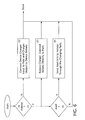
- FIG. 10 is a logic flow chart of one mode of operation of the handheld electronic device described herein.
- FIGS. 1-5 An improved electronic device 4 is indicated generally in FIGS. 1-5 .
- the electronic device 4 includes an improved handheld electronic device 8 and an improved holster 12.
- the holster 12 cooperates with the handheld electronic device 8, as will be set forth in greater detail below. Examples of handheld electronic devices are disclosed in U. S. Patent Nos. 6,452,588 and 6,489,950 .
- the holder or holster 12 includes a housing 40 formed with a cavity 44, a first charging apparatus 48, a second battery 52 and a second charging apparatus 56 (shown in FIG. 4 ).
- the first charging apparatus 48 and the second charging apparatus 56 are both electrically connected with the second battery 52.
- the holster 12 additionally includes a plurality of second contacts 60 (shown in FIG. 4 ) disposed on the housing 40 within the cavity 44 and, in the presently described exemplary embodiment depicted in FIGS. 1 , 2 , 4 and 5 , includes a power cord 64.
- the power cord (64) is electrically connectable with a suitable external power source 68 (illustrated in FIG.
- the housing 40 includes an opening 72 formed therein that enables the user to gain access to the keyboard 28 and observe the display 20 when the handheld device 8 is received in a first orientation (illustrated in FIG. 1 ) in the housing 40.
- the functionality of the whole system 4 can be enhanced by having the holster 12 indicate the state of the handheld electronic device 8 when the device 8 is holstered.
- the various alerts that it uses to communicate its state tend to be muffled. The user can then miss important events, such as incoming phone calls, incoming e-mail alerts and other text messages, approaching appointments, etc.
- the above alert types are highly customizable. For example, through the use of polyphonic sound synthesizers and callerIDTM, it is possible to assign unique ring tones to phone numbers in a pre-programmed user's list. Similarly, the capability currently exists to assign different alert types based on e-mail importance or sender.
- the notification device controlled by the handheld electronic device can be programmed to have a plurality of signal patterns, each corresponding to a different state of the handheld electronic device.
- the state of the handheld electronic device 8 could be the arrival of an e-mail and the signal pattern could correspond to the relative importance of the e-mail.
- the relative importance of the e-mail could be determined from the address of the sender.
- the exemplary embodiments described herein address the limited battery life of handheld devices by supplementing the charge stored in the handheld battery 32 with charge stored in an additional battery 52 built into the holster 12 through the built-in charging contacts 36 of the handheld electronic device 8 and the built-in mating charging contacts 60 of the holster 12.
- the exemplary embodiments described herein also do away with the problem of a user charging and carrying two separate batteries by effectively hiding the second battery 52 within an accessory, in this case the holster 12.
- New flexible battery technologies will allow the secondary battery to be built into plastic holsters or be woven into leather holsters.
- the exemplary embodiments described herein add intelligence to the holster 12 by adding a microcontroller 90, driver 94 and notification device 98 to the holster 12 as shown in FIG. 2 , preferably all powered by the second battery 52 in the holster 12.
- the exemplary embodiments described herein include a second battery 52 sealed within the holster 12 to provide additional charge to the primary handheld battery 32 through the charge contacts 36 and 60 should the primary battery 32 fall below a preset charge level, and power the electronics embedded in the holster 12.
- Included as part of the device and method described herein is an algorithm which controls the charging and discharging of the secondary battery 52 without the use of charging port 64 on the holster 12.
- the object of this exemplary embodiment is to have a battery 52 in the holster 12 that will act to supplement the device battery 32, thereby increasing the apparent operating time of the device and support intelligent communication between the device 8 and the holster 12.
- the holster battery 52 is preferably thin so as not to make the holster 12 bulky. Li-polymer cells satisfy this criterion. Accordingly, the holster battery 52 can be made very thin, and yet have a very large area for increased energy storage capacity. Secondly, modifications made to the electronic device are desirably minimal. Thirdly, the brunt of the cost of the modification may be borne by the improvement made to the holster 12 so as not to saddle those users that don't want to bear the cost of this improvement. Lastly, the holster battery 52 can be advantageously designed so as to meet safety requirements.
- the secondary battery 52 would be a fraction of the size of the primary battery 32; i.e., about 30%. This will, in most instances, permit a user to obtain an additional day or two of use before the handheld electronic device 8 has to be recharged from an external source. It is known that longer battery life improves the user's experience. Unfortunately, improving the technology of the battery 32 or providing a replaceable battery 32 increases the device cost. On the other hand, providing a higher capacity battery would increase the weight and size factors. While optimized software decreases handheld electronic device 8 battery consumption, it is effective up to a certain point.
- the secondary battery 52 in the holster 12 is at least approximately 1/3 larger than the operational battery 32 in the handheld electronic device 8 so that a smaller operational battery 32 with a size and capacity of about 1/3 of the current battery can be used.
- the operational battery 32 is installed on the handheld electronic device 8 to maintain it while the user is effectively working.
- the supplementary or secondary battery 52 is integrated in the holster 12 while the handheld electronic device 8 is in the holster 12 it would consume power from the supplementary battery 52 through power connectors 36 and 60 located in the bottom or back of the handheld electronic device 8.
- the operational battery 32 would be charged at the same time through these same contacts 36 and 60.
- the average handheld electronic device 8 is in its holster 12 approximately 95% of the time so the capacity of the operational battery 32 that is residing on the handheld electronic device does not need to be as high.
- the battery 52 residing on the holster 12 can be extended in capacity since its weight would not contribute to the weight of the electronic device 8 under this arrangement. If the battery 32 is taken out of a handheld electronic device 8 such as the BlackBerry device and held in the hand, it feels surprisingly light.
- the BlackBerry device itself weighs 136 grams. The battery adds an additional 26 grams to the weight. Thus, in this embodiment the weight can be minimized while extending the battery life.
- the user would need to charge only the holster 12.
- the battery 32 residing on the handheld electronic device 8 would charge itself from the holster's battery 52.
- the battery 32 on the handheld electronic device 8 does not need to be removable.
- the battery 52 on the holster 12 is discharged and the user wants to get her/his device working right away, then he/she just takes another holster - a procedure much easier than changing the battery 32 (and the device 8 is not even required to be restarted). In this way an effective removable battery is achieved in a more cost effective and user friendly way.
- the overall battery life of the handheld electronic device 8 can be improved and the weight of the handheld electronic device 8 can be decreased.
- the larger of the two batteries 32 and 52 is incorporated in the holster 12 or the handheld electronic device 8 will depend on the nature of the use of the handheld electronic device 8 and the relative times the device is situated in and out of the holster 12. If the handheld electronic device 8 is to spend extended periods of time out of the holster 12, then the larger of the two batteries 32 and 52 should be incorporated into the handheld electronic device 8. On the other hand, if the handheld electronic device 8 spends most of its time in the holster 12, then the weight of the handheld electronic device 8 can be reduced by incorporating the larger of the two batteries 32 and 52 in the holster 12.
- a manufacturer of the electronic device 4 can provide both options so that a user can select the option that is best suited to the way in which the user uses the electronic device 4.
- the primary battery 32 on the handheld electronic device 8 may be used to charge the holster battery 52 each time the handheld electronic device 8 is placed within its holster.
- a preselected amount of charge for example 100 mAhr (about 10% of the capacity of a typical handheld battery) is transferred from the handheld electronic device 8 to the holster battery 52 each time the handheld electronic device 8 is placed within the holster 12, to conserve power in the handheld electronic device 8.
- the handheld electronic device 8 may be separately charged from an external source, for example, when it is placed in a docking station, including charging circuitry to externally charge the handheld electronic device 8.
- the charge algorithm for the electronic device 4 is as follows:
- FIGS. 6 and 7 respectively show the logic and circuitry modifications that are applied to the handheld electronic device 8 to implement this embodiment. From FIG. 6 it can be appreciated that the handheld electronic device 8 detects whether it is holstered or not. This is readily done with handheld electronic devices 8 such as a BlackBerry by the use of a magnetic reed switch (not shown) inside the handheld electronic device 8 that detects a magnetic field generated by a small permanent magnet inside the holster 12.
- the handheld electronic device battery charging pads 36 shown in FIGS. 4 or 5
- the handheld electronic device battery charging pads 36 are made directly accessible to the holster 12 "charging" pads 60 (shown in FIGS. 4 or 5 ).
- the handheld electronic device 8 charging pads 36 act just as they would normally and that is to be normal charging pads 36, such as for cradle charging.
- the logic for this operation is illustrated in FIG. 6 and a block diagram of the battery charging circuit for the handheld electronic device 8 is shown in FIG. 7 .
- the reed switch When the reed switch is high, that is in position A, the charging pads 36 are connected directly to the battery 32 through a protection circuit module 76 which is an integral part of the battery pack 32.
- the protection circuit module 76 protects the battery on the handheld device 8 from overcharging.
- the reed switch 72 is low, that is position B, the handheld electronic device 8 battery charger 48 is interposed between the charging pads 36 and the battery pack 32. Thus, very little modification and expense has to be added to the handheld electronic device 8 to implement this embodiment.
- the microcontroller 90 accepts alert communications from the microprocessor 24 that are communicated through the pads 36 and 60, decodes those communications and issues the appropriate annunciation commands.
- the generally accepted way to implement this communication link is by sending data serially through the charging pads 36 and 60, with commands embedded in the serial data stream. This need not take additional connections beyond the two charging pads 36 and 60 that are on the holster 12 and handheld electronic device 8. A low-level data signal is made to ride on top of the DC voltage on the charging pads for this purpose.
- this low-level signal is DC balanced (such as NRZ, i.e., Non-return-to-zero), then the overall DC level on the pads is not changed, and the charging scheme detailed earlier is not affected.
- the logic for implementing this additional functionality is shown in FIG. 6 and FIG. 7 shows the microprocessor 24 communicating with the charging pads 36 through an interface circuit 102.
- the interface circuit 102 implements the low-level, DC balanced signaling protocol.
- the circuit diagram in FIG. 9 implements the flow diagram illustrated in FIG. 8 .
- Switch SW1 and SW2 perform the DC-DC converter/charger input/output reversing functions and are respectively connected to the input and the output of DC-DC converter/charger 78.
- Comparators COMP1 and COMP2 detect the state of the handheld electronic device battery 32. When the voltage is above the lower threshold level as inputted from the voltage divider circuit R2, R3 and R4, COMP2 outputs high. When the voltage is above the upper threshold, that is in this example 3.8 V, COMP1 turns high. In between, COMP1 will be low and COMP2 will be high. There cannot be a case where COMP1 is high and COMP2 is low.
- COMP1 when the battery is near full COMP1 will be high and COMP2 will be high enabling gate 84 to provide a high input to the SW3 switch input 88.
- the high input closes the SW3 switch and delivers a high output to the control input terminal of SW1 and SW2 which moves both switches to connect terminal A so that the handheld electronic device 8 charges the holster battery 52.
- the output of COMP1 When the handheld electronic device battery 32 is in its mid range, identified in Paragraph 2 immediately above, the output of COMP1 will be low and the output of COMP2 will be high providing a low output from the gate 84 to the control input terminal 88 of switch SW3.
- the low input opens the switch and opens circuits both SW1 and SW2 to the NO position and no charge sharing occurs.
- the capacitor C1 at the input to the comparators Comp1 and Comp2 functions as a low-pass filter that filters out all the serial data riding on the charging pads 60 so that the charging scheme is not affected by this "noise".
- all the electronics on the holster 12, including the notification device 98, is powered by the holster battery 52.
- the microcontroller 90 on the holster 12 can be programmed to go to sleep or even power down, and only wake up upon detecting a communication from the microprocessor 24 on the handheld electronic device 8. This would conserve power in the battery 52 so that it could be employed to extend the charge life of the battery 32 on the handheld electronic device 8. With the ability to accept commands from the handheld electronic device 8, almost all the hardware in the decision making process as to when to charge the holster battery 52 and when to give back the holster battery charge to the device 8 can be made in software. So, in essence, everything except the DC-DC converter can be done in the microcontroller 90, under software control. Alternatively, the functions can be handled as described above with the microcontroller 90 only managing the signals received from the microprocessor 24.
- the microcontroller 90 is programmed to enable or disable the notification device 98.
- the microprocessor 24 on the handheld electronic device 8 can be programmed to enable or disable the notification device 98. This latter arrangement is illustrated in the logic flow chart shown in FIG. 10 .
- the microprocessor 24 first identifies whether the notification device 98 is active. If the notification device 98 is active the microprocessor 24 sends a command for the notification device 98 to identify the state of the handheld electronic device 8 for a pre-selected period of time. After that pre-selected period of time has passed the notification device 98 is inactivated to conserve the power of the battery 52 (shown in FIG. 4 ).
- a short-range wireless link can be employed.
- Many handheld electronic devices already have Bluetooth® functionality built-in. Accordingly, all a user has to do is to pair the Bluetooth® device embedded in the holster 12 to the handheld electronic device Bluetooth® device. This would enable a user wearing an empty holster 12 to be alerted to an incoming message when the user's handheld electronic device 8 is in a cradle being charged or is in use outside the holster 12.
- the wireless link would also enable a user to eliminate a vibrator on the handheld electronic device 8, further reducing its weight and extending its onboard battery 32 operating time.
Priority Applications (3)
| Application Number | Priority Date | Filing Date | Title |
|---|---|---|---|
| EP10188115A EP2309361A1 (fr) | 2007-10-12 | 2007-10-12 | Dispositif électronique incluant un dispositif électronique portable doté d'un étui intelligent |
| EP07118415A EP2051154A1 (fr) | 2007-10-12 | 2007-10-12 | Dispositif électronique incluant un dispositif électronique portable doté d'un étui intelligent |
| CA2640903A CA2640903C (fr) | 2007-10-12 | 2008-10-10 | Dispositif electronique comprenant un dispositif electronique portatif avec etui intelligent |
Applications Claiming Priority (1)
| Application Number | Priority Date | Filing Date | Title |
|---|---|---|---|
| EP07118415A EP2051154A1 (fr) | 2007-10-12 | 2007-10-12 | Dispositif électronique incluant un dispositif électronique portable doté d'un étui intelligent |
Publications (1)
| Publication Number | Publication Date |
|---|---|
| EP2051154A1 true EP2051154A1 (fr) | 2009-04-22 |
Family
ID=39092077
Family Applications (2)
| Application Number | Title | Priority Date | Filing Date |
|---|---|---|---|
| EP07118415A Ceased EP2051154A1 (fr) | 2007-10-12 | 2007-10-12 | Dispositif électronique incluant un dispositif électronique portable doté d'un étui intelligent |
| EP10188115A Withdrawn EP2309361A1 (fr) | 2007-10-12 | 2007-10-12 | Dispositif électronique incluant un dispositif électronique portable doté d'un étui intelligent |
Family Applications After (1)
| Application Number | Title | Priority Date | Filing Date |
|---|---|---|---|
| EP10188115A Withdrawn EP2309361A1 (fr) | 2007-10-12 | 2007-10-12 | Dispositif électronique incluant un dispositif électronique portable doté d'un étui intelligent |
Country Status (2)
| Country | Link |
|---|---|
| EP (2) | EP2051154A1 (fr) |
| CA (1) | CA2640903C (fr) |
Cited By (8)
| Publication number | Priority date | Publication date | Assignee | Title |
|---|---|---|---|---|
| GB2487095A (en) * | 2011-01-10 | 2012-07-11 | Lingo Ltd | Protective case for handheld device charging from auxiliary battery |
| EP2575234A1 (fr) * | 2011-09-30 | 2013-04-03 | Research In Motion Limited | Gestion du cycle de vie de batterie d'un combiné de batterie double |
| EP2579122A1 (fr) * | 2011-10-07 | 2013-04-10 | Research In Motion Limited | Dispositif de notification |
| EP2622492A4 (fr) * | 2010-10-01 | 2015-08-12 | Z124 | Systèmes et procédés d'accueil de dispositifs électroniques portables |
| US9244491B2 (en) | 2011-08-31 | 2016-01-26 | Z124 | Smart dock for auxiliary devices |
| US9383770B2 (en) | 2011-08-31 | 2016-07-05 | Z124 | Mobile device that docks with multiple types of docks |
| US9507930B2 (en) | 2003-04-25 | 2016-11-29 | Z124 | Physical key secure peripheral interconnection |
| US9900418B2 (en) | 2011-09-27 | 2018-02-20 | Z124 | Smart dock call handling rules |
Families Citing this family (1)
| Publication number | Priority date | Publication date | Assignee | Title |
|---|---|---|---|---|
| US9288785B2 (en) * | 2014-03-04 | 2016-03-15 | Denso International America, Inc. | System for reminding user to remove smartphone from vehicle when exiting |
Citations (10)
| Publication number | Priority date | Publication date | Assignee | Title |
|---|---|---|---|---|
| EP0274279A2 (fr) | 1987-01-08 | 1988-07-13 | Nec Corporation | Dispositif de fixation pour récepteur d'appel de personnes ayant des fonctions supplémentaires |
| US5353017A (en) | 1991-08-06 | 1994-10-04 | Matsushita Electric Industrial Co., Ltd. | Call selective receiver built in with vibrator |
| US5551079A (en) | 1992-04-30 | 1996-08-27 | Silcom Research Limited | Radio pager holster assembly |
| WO1999053621A1 (fr) | 1998-04-14 | 1999-10-21 | Qualcomm Incorporated | Procede et appareil assurant l'interface entre un dispositif de communication sans fil et un accessoire |
| US20030030412A1 (en) | 2001-08-10 | 2003-02-13 | Seiko Epson Corporation | Power control circuit, electronic instrument, and charging method |
| US20030178967A1 (en) | 2002-03-21 | 2003-09-25 | Khatri Nizam Issa | Apparatus and method for the power management of operatively connected modular devices |
| EP1569315A1 (fr) | 2004-02-26 | 2005-08-31 | Research In Motion Limited | Appareil et procédé pour un configuration à deux batteries d'un appareil portable et dispositif de support |
| EP1600907A1 (fr) | 2004-05-27 | 2005-11-30 | Research In Motion Limited | Dispositif électronique à main ayant un vibrateur avec des intensités de vibration différentes et un procédé pour faire vibrer un tel dispositif |
| JP2006260183A (ja) | 2005-03-17 | 2006-09-28 | Canon Inc | 電子メール端末装置 |
| US20060226805A1 (en) | 2005-04-11 | 2006-10-12 | Tsung-I Yu | Mobile battery-charging container |
Family Cites Families (5)
| Publication number | Priority date | Publication date | Assignee | Title |
|---|---|---|---|---|
| US6489950B1 (en) | 1998-06-26 | 2002-12-03 | Research In Motion Limited | Hand-held electronic device with auxiliary input device |
| US6278442B1 (en) | 1998-06-26 | 2001-08-21 | Research In Motion Limited | Hand-held electronic device with a keyboard optimized for use with the thumbs |
| AU2001278012A1 (en) * | 2000-07-25 | 2002-02-05 | Khyber Technologies Corporation | Wearable point-of-sale device having a detachable handheld unit and a printing holster |
| ATE557334T1 (de) * | 2005-07-07 | 2012-05-15 | Research In Motion Ltd | Behälter für tragbares gerät und verfahren zu seiner bedienung |
| US7715831B2 (en) * | 2006-03-24 | 2010-05-11 | Sony Ericssson Mobile Communications, Ab | Methods, systems, and devices for detecting and indicating loss of proximity between mobile devices |
-
2007
- 2007-10-12 EP EP07118415A patent/EP2051154A1/fr not_active Ceased
- 2007-10-12 EP EP10188115A patent/EP2309361A1/fr not_active Withdrawn
-
2008
- 2008-10-10 CA CA2640903A patent/CA2640903C/fr active Active
Patent Citations (10)
| Publication number | Priority date | Publication date | Assignee | Title |
|---|---|---|---|---|
| EP0274279A2 (fr) | 1987-01-08 | 1988-07-13 | Nec Corporation | Dispositif de fixation pour récepteur d'appel de personnes ayant des fonctions supplémentaires |
| US5353017A (en) | 1991-08-06 | 1994-10-04 | Matsushita Electric Industrial Co., Ltd. | Call selective receiver built in with vibrator |
| US5551079A (en) | 1992-04-30 | 1996-08-27 | Silcom Research Limited | Radio pager holster assembly |
| WO1999053621A1 (fr) | 1998-04-14 | 1999-10-21 | Qualcomm Incorporated | Procede et appareil assurant l'interface entre un dispositif de communication sans fil et un accessoire |
| US20030030412A1 (en) | 2001-08-10 | 2003-02-13 | Seiko Epson Corporation | Power control circuit, electronic instrument, and charging method |
| US20030178967A1 (en) | 2002-03-21 | 2003-09-25 | Khatri Nizam Issa | Apparatus and method for the power management of operatively connected modular devices |
| EP1569315A1 (fr) | 2004-02-26 | 2005-08-31 | Research In Motion Limited | Appareil et procédé pour un configuration à deux batteries d'un appareil portable et dispositif de support |
| EP1600907A1 (fr) | 2004-05-27 | 2005-11-30 | Research In Motion Limited | Dispositif électronique à main ayant un vibrateur avec des intensités de vibration différentes et un procédé pour faire vibrer un tel dispositif |
| JP2006260183A (ja) | 2005-03-17 | 2006-09-28 | Canon Inc | 電子メール端末装置 |
| US20060226805A1 (en) | 2005-04-11 | 2006-10-12 | Tsung-I Yu | Mobile battery-charging container |
Cited By (9)
| Publication number | Priority date | Publication date | Assignee | Title |
|---|---|---|---|---|
| US9507930B2 (en) | 2003-04-25 | 2016-11-29 | Z124 | Physical key secure peripheral interconnection |
| EP2622492A4 (fr) * | 2010-10-01 | 2015-08-12 | Z124 | Systèmes et procédés d'accueil de dispositifs électroniques portables |
| GB2487095A (en) * | 2011-01-10 | 2012-07-11 | Lingo Ltd | Protective case for handheld device charging from auxiliary battery |
| US9244491B2 (en) | 2011-08-31 | 2016-01-26 | Z124 | Smart dock for auxiliary devices |
| US9383770B2 (en) | 2011-08-31 | 2016-07-05 | Z124 | Mobile device that docks with multiple types of docks |
| US9900418B2 (en) | 2011-09-27 | 2018-02-20 | Z124 | Smart dock call handling rules |
| US10652383B2 (en) | 2011-09-27 | 2020-05-12 | Z124 | Smart dock call handling rules |
| EP2575234A1 (fr) * | 2011-09-30 | 2013-04-03 | Research In Motion Limited | Gestion du cycle de vie de batterie d'un combiné de batterie double |
| EP2579122A1 (fr) * | 2011-10-07 | 2013-04-10 | Research In Motion Limited | Dispositif de notification |
Also Published As
| Publication number | Publication date |
|---|---|
| CA2640903C (fr) | 2014-09-23 |
| EP2309361A1 (fr) | 2011-04-13 |
| CA2640903A1 (fr) | 2009-04-12 |
Similar Documents
| Publication | Publication Date | Title |
|---|---|---|
| US7863862B2 (en) | Handheld electronic device with holster having a notification device | |
| CA2640903C (fr) | Dispositif electronique comprenant un dispositif electronique portatif avec etui intelligent | |
| US7986123B2 (en) | Apparatus and method for the power management of operatively connected batteries respectively on a handheld electronic device and a holder for the handheld electronic device | |
| US7479759B2 (en) | Electronic device including handheld electronic device with dual battery configuration, and associated method | |
| JP2002505514A (ja) | バッテリパック情報を通知する方法及び装置 | |
| EP1008203A1 (fr) | Ensemble boitier pour piles | |
| CA2498080C (fr) | Appareil electronique comprenant un dispositif electronique a main et deux batteries, et methode connexe | |
| NZ527050A (en) | Back-up battery for a cellular telephone | |
| WO1999043095A1 (fr) | Ensemble d'alimentation pour telephone portable | |
| AU723981B2 (en) | Intelligent battery charging in a hand-held phone | |
| US5610497A (en) | Method and apparatus for providing continuous power to a battery powered device during battery transfer | |
| US7248902B2 (en) | Multi-mode power supply device of wireless earphone | |
| EP1921725B1 (fr) | Dispositif électronique, comportant des dispositifs électroniques portables, avec configuration double batterie et procédé correspondant | |
| US20060250108A1 (en) | Supplemental battery for a portable electronic device | |
| KR20110005073U (ko) | 태양 전지를 구비한 휴대폰 분실 방지 장치 및 시스템 | |
| JP2001309562A (ja) | 携帯通信機器用充電器 | |
| KR20080004844U (ko) | 이동기기에 대한 휴대용 크레들 충전기 | |
| WO2008007965A1 (fr) | Dispositif de recharge et de maintien de batterie | |
| KR20070000812U (ko) | 유에스비 포트를 이용한 충전식 에프엠 라디오 및휴대전화보조배터리 | |
| KR101091222B1 (ko) | 백업 배터리를 내장한 휴대 단말기 | |
| GB2400276A (en) | A cordless telephone device alternately powered by a battery and PSTN line | |
| KR100260894B1 (ko) | 단속검출형 고속충전 및 충전조절회로 | |
| KR20030046076A (ko) | 배터리의 충전 상태를 표시하기 위한 충전기 | |
| KR20030039155A (ko) | 이동통신 단말기의 배터리 충전 상태를 표시하기 위한충전기 |
Legal Events
| Date | Code | Title | Description |
|---|---|---|---|
| PUAI | Public reference made under article 153(3) epc to a published international application that has entered the european phase |
Free format text: ORIGINAL CODE: 0009012 |
|
| 17P | Request for examination filed |
Effective date: 20071017 |
|
| AK | Designated contracting states |
Kind code of ref document: A1 Designated state(s): AT BE BG CH CY CZ DE DK EE ES FI FR GB GR HU IE IS IT LI LT LU LV MC MT NL PL PT RO SE SI SK TR |
|
| AX | Request for extension of the european patent |
Extension state: AL BA HR MK RS |
|
| AKX | Designation fees paid |
Designated state(s): AT BE BG CH CY CZ DE DK EE ES FI FR GB GR HU IE IS IT LI LT LU LV MC MT NL PL PT RO SE SI SK TR |
|
| STAA | Information on the status of an ep patent application or granted ep patent |
Free format text: STATUS: THE APPLICATION HAS BEEN REFUSED |
|
| 18R | Application refused |
Effective date: 20120202 |