EP2050939A1 - Multi-stage supercharging exhaust turbosupercharger - Google Patents
Multi-stage supercharging exhaust turbosupercharger Download PDFInfo
- Publication number
- EP2050939A1 EP2050939A1 EP20070792317 EP07792317A EP2050939A1 EP 2050939 A1 EP2050939 A1 EP 2050939A1 EP 20070792317 EP20070792317 EP 20070792317 EP 07792317 A EP07792317 A EP 07792317A EP 2050939 A1 EP2050939 A1 EP 2050939A1
- Authority
- EP
- European Patent Office
- Prior art keywords
- pressure
- compressor
- bypass
- exhaust
- low
- Prior art date
- Legal status (The legal status is an assumption and is not a legal conclusion. Google has not performed a legal analysis and makes no representation as to the accuracy of the status listed.)
- Granted
Links
Images




Classifications
-
- F—MECHANICAL ENGINEERING; LIGHTING; HEATING; WEAPONS; BLASTING
- F02—COMBUSTION ENGINES; HOT-GAS OR COMBUSTION-PRODUCT ENGINE PLANTS
- F02B—INTERNAL-COMBUSTION PISTON ENGINES; COMBUSTION ENGINES IN GENERAL
- F02B37/00—Engines characterised by provision of pumps driven at least for part of the time by exhaust
- F02B37/013—Engines characterised by provision of pumps driven at least for part of the time by exhaust with exhaust-driven pumps arranged in series
-
- F—MECHANICAL ENGINEERING; LIGHTING; HEATING; WEAPONS; BLASTING
- F01—MACHINES OR ENGINES IN GENERAL; ENGINE PLANTS IN GENERAL; STEAM ENGINES
- F01N—GAS-FLOW SILENCERS OR EXHAUST APPARATUS FOR MACHINES OR ENGINES IN GENERAL; GAS-FLOW SILENCERS OR EXHAUST APPARATUS FOR INTERNAL-COMBUSTION ENGINES
- F01N13/00—Exhaust or silencing apparatus characterised by constructional features
- F01N13/08—Other arrangements or adaptations of exhaust conduits
- F01N13/10—Other arrangements or adaptations of exhaust conduits of exhaust manifolds
-
- F—MECHANICAL ENGINEERING; LIGHTING; HEATING; WEAPONS; BLASTING
- F02—COMBUSTION ENGINES; HOT-GAS OR COMBUSTION-PRODUCT ENGINE PLANTS
- F02B—INTERNAL-COMBUSTION PISTON ENGINES; COMBUSTION ENGINES IN GENERAL
- F02B37/00—Engines characterised by provision of pumps driven at least for part of the time by exhaust
- F02B37/004—Engines characterised by provision of pumps driven at least for part of the time by exhaust with exhaust drives arranged in series
-
- F—MECHANICAL ENGINEERING; LIGHTING; HEATING; WEAPONS; BLASTING
- F02—COMBUSTION ENGINES; HOT-GAS OR COMBUSTION-PRODUCT ENGINE PLANTS
- F02B—INTERNAL-COMBUSTION PISTON ENGINES; COMBUSTION ENGINES IN GENERAL
- F02B37/00—Engines characterised by provision of pumps driven at least for part of the time by exhaust
- F02B37/12—Control of the pumps
-
- F—MECHANICAL ENGINEERING; LIGHTING; HEATING; WEAPONS; BLASTING
- F02—COMBUSTION ENGINES; HOT-GAS OR COMBUSTION-PRODUCT ENGINE PLANTS
- F02B—INTERNAL-COMBUSTION PISTON ENGINES; COMBUSTION ENGINES IN GENERAL
- F02B37/00—Engines characterised by provision of pumps driven at least for part of the time by exhaust
- F02B37/12—Control of the pumps
- F02B37/16—Control of the pumps by bypassing charging air
-
- F—MECHANICAL ENGINEERING; LIGHTING; HEATING; WEAPONS; BLASTING
- F02—COMBUSTION ENGINES; HOT-GAS OR COMBUSTION-PRODUCT ENGINE PLANTS
- F02B—INTERNAL-COMBUSTION PISTON ENGINES; COMBUSTION ENGINES IN GENERAL
- F02B39/00—Component parts, details, or accessories relating to, driven charging or scavenging pumps, not provided for in groups F02B33/00 - F02B37/00
-
- F—MECHANICAL ENGINEERING; LIGHTING; HEATING; WEAPONS; BLASTING
- F02—COMBUSTION ENGINES; HOT-GAS OR COMBUSTION-PRODUCT ENGINE PLANTS
- F02B—INTERNAL-COMBUSTION PISTON ENGINES; COMBUSTION ENGINES IN GENERAL
- F02B39/00—Component parts, details, or accessories relating to, driven charging or scavenging pumps, not provided for in groups F02B33/00 - F02B37/00
- F02B39/02—Drives of pumps; Varying pump drive gear ratio
-
- F—MECHANICAL ENGINEERING; LIGHTING; HEATING; WEAPONS; BLASTING
- F04—POSITIVE - DISPLACEMENT MACHINES FOR LIQUIDS; PUMPS FOR LIQUIDS OR ELASTIC FLUIDS
- F04D—NON-POSITIVE-DISPLACEMENT PUMPS
- F04D17/00—Radial-flow pumps, e.g. centrifugal pumps; Helico-centrifugal pumps
- F04D17/08—Centrifugal pumps
- F04D17/10—Centrifugal pumps for compressing or evacuating
- F04D17/12—Multi-stage pumps
- F04D17/14—Multi-stage pumps with means for changing the flow-path through the stages, e.g. series-parallel, e.g. side-loads
-
- F—MECHANICAL ENGINEERING; LIGHTING; HEATING; WEAPONS; BLASTING
- F04—POSITIVE - DISPLACEMENT MACHINES FOR LIQUIDS; PUMPS FOR LIQUIDS OR ELASTIC FLUIDS
- F04D—NON-POSITIVE-DISPLACEMENT PUMPS
- F04D29/00—Details, component parts, or accessories
- F04D29/40—Casings; Connections of working fluid
- F04D29/42—Casings; Connections of working fluid for radial or helico-centrifugal pumps
- F04D29/4206—Casings; Connections of working fluid for radial or helico-centrifugal pumps especially adapted for elastic fluid pumps
- F04D29/4213—Casings; Connections of working fluid for radial or helico-centrifugal pumps especially adapted for elastic fluid pumps suction ports
-
- F—MECHANICAL ENGINEERING; LIGHTING; HEATING; WEAPONS; BLASTING
- F05—INDEXING SCHEMES RELATING TO ENGINES OR PUMPS IN VARIOUS SUBCLASSES OF CLASSES F01-F04
- F05D—INDEXING SCHEME FOR ASPECTS RELATING TO NON-POSITIVE-DISPLACEMENT MACHINES OR ENGINES, GAS-TURBINES OR JET-PROPULSION PLANTS
- F05D2220/00—Application
- F05D2220/40—Application in turbochargers
-
- Y—GENERAL TAGGING OF NEW TECHNOLOGICAL DEVELOPMENTS; GENERAL TAGGING OF CROSS-SECTIONAL TECHNOLOGIES SPANNING OVER SEVERAL SECTIONS OF THE IPC; TECHNICAL SUBJECTS COVERED BY FORMER USPC CROSS-REFERENCE ART COLLECTIONS [XRACs] AND DIGESTS
- Y02—TECHNOLOGIES OR APPLICATIONS FOR MITIGATION OR ADAPTATION AGAINST CLIMATE CHANGE
- Y02T—CLIMATE CHANGE MITIGATION TECHNOLOGIES RELATED TO TRANSPORTATION
- Y02T10/00—Road transport of goods or passengers
- Y02T10/10—Internal combustion engine [ICE] based vehicles
- Y02T10/12—Improving ICE efficiencies
-
- Y—GENERAL TAGGING OF NEW TECHNOLOGICAL DEVELOPMENTS; GENERAL TAGGING OF CROSS-SECTIONAL TECHNOLOGIES SPANNING OVER SEVERAL SECTIONS OF THE IPC; TECHNICAL SUBJECTS COVERED BY FORMER USPC CROSS-REFERENCE ART COLLECTIONS [XRACs] AND DIGESTS
- Y10—TECHNICAL SUBJECTS COVERED BY FORMER USPC
- Y10T—TECHNICAL SUBJECTS COVERED BY FORMER US CLASSIFICATION
- Y10T137/00—Fluid handling
- Y10T137/7722—Line condition change responsive valves
- Y10T137/7837—Direct response valves [i.e., check valve type]
- Y10T137/7898—Pivoted valves
-
- Y—GENERAL TAGGING OF NEW TECHNOLOGICAL DEVELOPMENTS; GENERAL TAGGING OF CROSS-SECTIONAL TECHNOLOGIES SPANNING OVER SEVERAL SECTIONS OF THE IPC; TECHNICAL SUBJECTS COVERED BY FORMER USPC CROSS-REFERENCE ART COLLECTIONS [XRACs] AND DIGESTS
- Y10—TECHNICAL SUBJECTS COVERED BY FORMER USPC
- Y10T—TECHNICAL SUBJECTS COVERED BY FORMER US CLASSIFICATION
- Y10T137/00—Fluid handling
- Y10T137/8593—Systems
- Y10T137/877—With flow control means for branched passages
- Y10T137/87788—With valve or movable deflector at junction
- Y10T137/87812—Pivoted valve or deflector
Definitions
- the present invention relates to a multistage exhaust turbocharger for an internal combustion engine, the turbocharger comprising a high-pressure stage turbocharger having a high-pressure turbine drivable by exhaust gas from the engine and a low-pressure stage turbocharger having a low-pressure turbine drivable by exhaust gas from the high-pressure turbine, the turbochargers being arranged sequentially in the flow path of the exhaust gas, and supply air for the engine pressurized by a low-pressure compressor of the low-pressure stage turbocharger being supplied via an air supply channel to a high-pressure compressor of the high-pressure stage turbocharger to be further pressurized by the high-pressure compressor.
- multistage (two-stage) exhaust turbo-charging system in which a high-pressure stage turbocharger having a high-pressure turbine drivable by exhaust gas from the exhaust manifold of the engine cylinder and a low-pressure stage turbocharger having a low-pressure turbine drivable by exhaust gas from the high-pressure turbine are arranged sequentially in the flow path of the exhaust gas, and supply air for the engine pressurized by a low-pressure compressor of the low-pressure stage turbocharger is supplied via an air supply channel to a high pressure compressor of the high-pressure stage turbocharger to be further pressurized by the high-pressure compressor and charged to the engine.
- FIG.9 is a schematic representation of such a two-stage supercharging system as disclosed for example in US 2003/0159442 A1 , US 6,378,308 B1 , and JP 59-82526 .
- reference numeral 103 is an exhaust manifold
- 1 is a high-pressure stage turbocharger having a high-pressure turbine 1a and a high-pressure compressor 1b connected to the turbine 1a by a shaft
- 2 is a low-pressure stage turbocharger having a low-pressure turbine 2a and a low-pressure compressor 2b connected to the turbine 2a by a shaft.
- Reference numeral 117 is an exhaust bypass valve device for controlling the flow rate of exhaust gas flowing in a exhaust bypass pipe 116, 5 is a compressor bypass valve device for controlling the flow rate of bypassed supply air flowing in a high-pressure compressor bypass pipe 111.
- both the exhaust bypass valve device 117 and compressor bypass valve device 5 are closed.
- the exhaust gas flowing out from the exhaust manifold 103 drives both the high-pressure turbine 1a of the high-pressure stage turbocharger 1 and low-pressure turbine 1b of the low-pressure stage turbocharger 2.
- supply air pressurized by the low-pressure compressor 2b connected to the low-pressure turbine 2a is further pressurized by the high-pressure compressor 1b connected to the high-pressure turbine 1a, and supplied to each cylinder of the engine as charge air for combustion in the cylinders.
- Supercharge pressure can be increased in order to increase charging pressure and output of engine by performing two-stage supercharging like this in a low, middle speed operating range of the engine.
- the compressor bypass valve device 5 When allowing the engine to operate in a single-stage supercharging state by the low-pressure stage turbocharger 2 in a high speed operating range by allowing the exhaust gas and supply air to bypass the high-pressure stage turbocharger 2, the compressor bypass valve device 5 is opened and the opening of the exhaust bypass valve device 117 is controlled so that desired pressure of charge air is produced.
- a comparatively large installation space is required in the engine room to install an engine equipped with a two-stage exhaust turbocharger of this type because it is inevitably increased in bulk as compared with a single-stage one.
- a high-pressure stage turbocharger 1 and low-pressure stage exhaust turbocharger 2 are arranged three dimensionally in order to make it possible to connect them with exhaust and air supply paths of minimum length and reduce the bulk of the two-stage exhaust turbocharger assembly.
- the casings of the high-pressure stage and low-pressure stage turbochargers are composed completely separately with exhaust and air supply channels for connecting them being provided, the bulk of the two-stage exhaust turbocharger assembly is still not reduced enough, and it is still not easy to secure an installation space for mounting the engine in a narrow engine room of a vehicle.
- the present invention was made in light of the problems in conventional art, and the object is to provide a multistage exhaust turbocharger which is simplified in construction and reduced in bulk, thereby obtaining an engine equipped with the multistage exhaust turbocharger easily mountable in a narrow engine room of a vehicle can be obtained.
- the present invention proposes a multistage exhaust turbocharger for an internal combustion engine including a high-pressure stage turbocharger having a high-pressure turbine drivable by exhaust gas exhausted from an exhaust manifold of the engine and a low-pressure stage turbocharger having a low-pressure turbine drivable by exhaust gas flowed out from the high-pressure turbine after driving the turbine, the turbochargers being arranged sequentially in the flow path of the exhaust gas of the engine, supply air for the engine pressurized by a low-pressure compressor of the low-pressure stage turbocharger being supplied via an air supply channel to a high-pressure compressor of the high-pressure stage turbocharger to be further pressurized by the high-pressure compressor, a compressor bypass valve device being provided which allows a part of the supply air to bypass the high-pressure compressor via a compressor bypass channel, wherein a high-pressure compressor cover of the high-pressure stage turbocharger is composed such that it has a compressor inlet passage, a bypass inlet passage, a switching aperture between both the passage
- the high-pressure compressor cover is composed such that it has a compressor inlet passage for supply air to be introduced to the high-pressure compressor, a bypass inlet passage which is communicated with the compressor inlet passage via the switching aperture when the aperture is opened by the bypass valve body, and a bypass outlet pipe part extending at a right angle to the rotation axis of the high-pressure compressor to introduce bypass air passed through the aperture to the compressor bypass channel which is to be connected to the bypass outlet pipe part which is formed integral with the compressor cover extending as mentioned above adjacent the bypass valve device unit installed on the compressor cover, so the high-pressure compressor cover has the supply air inlet passage for introducing supply air to the high-pressure compressor, the bypass inlet passage through which bypass air flows to the compressor bypass channel, and the bypass outlet pipe part integral with it, and any piping is not needed to connect them.
- construction of the air inlet part of the high-pressure compressor and the connecting part thereof to the compressor bypass channel become compact and reduced in bulk, as a result installation space of the high-pressure compressor can be reduced, and an engine equipped with a two-stage exhaust turbocharger easy to be mounted in a narrow engine room of a vehicle can be obtained.
- the compressor bypass valve device as a unit including the compressor bypass valve for opening and closing the switching aperture between the compressor inlet passage and the bypass outlet passage and an actuator for driving the compressor bypass valve, installation of the compressor bypass valve device is facilitated, which contributes to reduction in assembling cost.
- the seat surface of said bypass valve body actuated by the actuator to seat on and depart from a valve seat formed along the peripheral part of the switching aperture to open and close the switching aperture is formed into an arcuate surface in cross-section.
- the seat surface of the valve body seats on the valve seat formed on the partition wall with line contact, so minute profile inaccuracy of the seat surface and valve seat is accommodated, even contact between the seat surfaces of the valve body and the valve seat plane can be attained, variation in sealing function of the bypass valve is eliminated, and a compressor bypass valve device having stable sealing function can be obtained.
- the invention proposes a multistage exhaust turbocharger for an internal combustion engine including a high-pressure stage turbocharger having a high-pressure turbine drivable by exhaust gas exhausted from an exhaust manifold of the engine and a low-pressure stage turbocharger having a low-pressure turbine drivable by exhaust gas flowed out from the high-pressure turbine after driving the turbine, the turbochargers being arranged sequentially in the flow path of the exhaust gas of the engine, supply air for the engine pressurized by a low-pressure compressor of the low-pressure stage turbocharger being supplied via an air supply channel to a high-pressure compressor of the high-pressure stage turbocharger to be further pressurized by the high-pressure compressor, a compressor bypass valve device being provided which allows a part of the supply air to bypass the high-pressure compressor via a compressor bypass channel, wherein a high-pressure turbine housing is cast integral with the exhaust manifold, an exhaust gas guide member is attached to the high-pressure turbine housing at an exhaust gas outlet side flange thereof, and a low-pressure turbine
- the flange face of the exhaust gas exit side flange of the high-pressure turbine housing is perpendicular to flange faces of flanges of the exhaust manifold for attaching the manifold to the engine.
- the exhaust gas guide member is attached to the high-pressure turbine housing cast integral with the exhaust manifold and the low-pressure turbine housing is attached to the exhaust gas guide member at its low-pressure turbine mounting flange extending in a direction parallel to the rotation axis of the high-pressure stage turbocharger, the high-pressure turbine housing, the exhaust gas guide member, and the low-pressure turbine housing can be connected directly one another without the need for providing any piping between them.
- construction of the connecting part between the turbine housing of the high-pressure stage turbocharger and the turbine housing of the low-pressure stage turbocharger becomes compact, as a result installation space of the turbine housing of the high-pressure stage turbocharger and the turbine housing of the low-pressure stage turbocharger can be reduced, and an engine equipped with a two-stage exhaust turbocharger easy to be mounted in a narrow engine room of a vehicle can be obtained.
- machining of the flange face of each of the flanges of the exhaust manifold can be facilitated, for the flange faces are perpendicular to the flange face of the exhaust gas exit side flange of the high-pressure turbine housing, and the flange faces of the flanges of the exhaust manifold can be machined using the flange face of the exhaust gas exit side flange of the turbine housing as a reference plane.
- the high-pressure compressor cover by composing the high-pressure compressor cover such that it has the compressor inlet passage, the bypass inlet passage which is communicated with the compressor inlet passage via the switching aperture when the aperture is opened by the bypass valve body, and a bypass outlet pipe part communicating with the bypass inlet passage, the high-pressure compressor cover is composed integral with the supply air inlet passage for introducing supply air to the high-pressure compressor, the bypass inlet passage through which bypass air flows to the compressor bypass channel via the bypass outlet pipe part when the switching aperture is opened by the compressor bypass valve device, and the bypass outlet pipe part to which the compressor bypass channel is to be connected, without the need for providing any piping between them.
- construction of the air inlet part of the high-pressure compressor and the connecting part thereof to the compressor bypass channel become compact and reduced in bulk, as a result installation space of the high-pressure compressor can be reduced, and an engine equipped with a two-stage exhaust turbocharger easy to be mounted in a narrow engine room of a vehicle can be obtained.
- the compressor bypass valve device as a unit including the compressor bypass valve for opening and closing the switching aperture between the compressor inlet passage and the bypass outlet passage and an actuator for driving the compressor bypass valve, installation of the compressor bypass valve device is facilitated, which contributes to reduction in assembling cost.
- the high-pressure turbine housing, the exhaust gas guide member, and the low-pressure turbine housing can be connected directly one another without the need for providing any piping between them.
- construction of the connecting part between the turbine housing of the high-pressure stage turbocharger and the turbine housing of the low-pressure stage turbocharger becomes compact, as a result installation space of the turbine housing of the high-pressure stage turbocharger and the turbine housing of the low-pressure stage turbocharger can be reduced, and an engine equipped with a two-stage exhaust turbocharger easy to be mounted in a narrow engine room of a vehicle can be obtained.
- machining of the flange face of each of the flanges of the exhaust manifold can be facilitated by using the flange face, which is perpendicular to the flange faces of the exhaust manifold, of the exhaust gas exit side flange of the high-pressure turbine housing as a reference plane.
- FIG.8 is a schematic diagram showing the air supply and exhaust system of an engine equipped with a two-stage exhaust turbocharger to which the present invention is applied.
- reference numeral 100 is an engine
- 101 is cylinders of the engine (four cylinders in the drawing)
- 102 is an intake manifold
- 103 is an exhaust manifold
- 1 is a high-pressure stage turbocharger having a high-pressure turbine 1a and a high-pressure compressor 1b connected by a shaft 3 to the turbine 1a
- 2 is a low-pressure stage turbocharger having a low-pressure turbine 2a and a low-pressure compressor 2b connected by a shaft 4 to the turbine 2a.
- Reference numeral 104 is a high-pressure exhaust channel connecting the exhaust outlet of the exhaust manifold 103 to the exhaust inlet of the high-pressure turbine 1a
- 115 is an exhaust channel connecting the exhaust outlet of the high-pressure turbine 1a to the inlet of the low-pressure turbine 2a
- Reference numeral 118 is an exhaust pipe for exhausting the exhaust gas flowing out from the low-pressure turbine 2a.
- Reference numeral 105 is an exhaust bypass channel for introducing the exhaust gas from the exhaust manifold 103 to the low-pressure turbine 2a bypassing the high-pressure turbine 1a
- 106 is a stage control valve for controlling the flow rate of the bypassing exhaust gas
- Reference numeral 116 is an exhaust bypass channel for introducing the exhaust gas flowing in the exhaust channel 115 to the exhaust pipe 118 bypassing the low-pressure turbine 2a
- 117 is an exhaust bypass valve device for controlling the flow rate of the bypassing exhaust gas flowing in the exhaust bypass channel 116.
- Reference numeral 119 is a suction pipe for introducing air from outside to the inlet of the low-pressure compressor 2b.
- Reference numeral 21 is an air supply channel connecting the outlet of the low-pressure compressor 2b to the inlet of the high-pressure compressor 1b.
- Reference numeral 108 is an air supply pipe connecting the outlet of the high-pressure compressor 1b to the inlet manifold 102, and 107 is an air cooler provided at the air supply pipe 108 to cool the air charged to the engine.
- Reference numeral 12 is a high-pressure compressor bypass channel for introducing the supply air to the air supply pipe 108 bypassing the high-pressure compressor 1b, and 5 is a compressor bypass valve device for controlling the flow rate of the bypassing supply air flowing in the compressor bypass channel 12.
- Reference numeral 109 is an EGR conduit for extracting a part of the exhaust gas from the exhaust manifold 103 and introducing it to the air supply pipe 108 as exhaust recirculation gas
- 110 is an EGR valve for controlling the flow rate of the exhaust recirculation gas.
- both the exhaust bypass valve device 117 and compressor bypass valve device 5 are closed when operating complete two-stage supercharging state in a low speed range, and when operating in variable two-stage ranges, the compressor bypass valve device 5 and the exhaust bypass valve device 117 are closed and the opening of the stage control valve 106 is controlled.
- the exhaust gas from the exhaust manifold 103 drives the high-pressure turbine 1a and low-pressure turbine 2a.
- supply air pressurized by the low-pressure compressor 2b is further pressurized by the high-pressure compressor 1b, then cooled by the air cooler 107, and supplied to the cylinders 101 of the engine 100 as charge air for combustion of fuel injected into the cylinders 101.
- Supercharge pressure can be increased to increase engine output by performing two-stage supercharging like this in a low, middle speed operating range of the engine.
- stage control valve 106 and compressor bypass valve device 5 are opened and the opening of the exhaust bypass valve device 117 is controlled so that desired pressure of charge air is produced.
- the present invention relates to improvement in structure of the two-stage exhaust turbocharger which works as mentioned above.
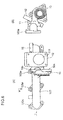
- FIG.1 is aside elevation showing the total construction of the first embodiment of the two-stage exhaust turbocharger according to the invention
- FIG.2 is a sectional view of the first embodiment of FIG.1 along the center line of the rotor shaft of the high-pressure stage turbocharger
- FIG. 3A is a perspective external view of the high-pressure compressor cover provided with the compressor bypass valve device
- FIG. 3B is an external view of the compressor bypass valve device
- FIG.4 is a sectional view of the high-pressure compressor cover.
- reference numeral 1 is a high-pressure stage turbocharger having a high-pressure turbine 1a and a high-pressure compressor 1b connected to the turbine 1a by a shaft 3 (see FIG. 8 ), 2 is a low-pressure stage turbocharger having a low-pressure turbine 2a and a low-pressure compressor 2b connected to the turbine 2a by a shaft 4(see FIG.8 ).
- Reference numeral 10 is a high-pressure turbine housing of the high-pressure stage turbocharger 1
- 9 is a high-pressure compressor cover
- 11 is an exhaust channel
- Reference numeral 2s is a low-pressure turbine housing of the low-pressure stage turbocharger 2
- 2t is a low-pressure compressor cover.
- Reference numeral 21 is an air supply channel connecting the low-pressure compressor cover 2t to the high-pressure compressor cover 9.
- the air supply channel 21 is made of metal material, such as a steel pipe, and aluminum pipe, or a resin or hard rubber pipe having flexibility.
- the channel 21 is connected to the compressor cover 2t and the compressor cover 9 by means of a clamp or other connection means respectively.
- reference numeral 10 is a high-pressure turbine housing 10 of cast metal
- 1a is a high-pressure turbine of radial flow type
- 1b is a high-pressure compressor connected to the turbine 1a
- 3 is a high-pressure stage rotor shaft connecting the turbine 1a and the compressor 1b
- 9 is a high-pressure compressor made of cast metal
- 6 is a high-pressure stage bearing housing made of cast metal.
- Reference numeral 11 is an exhaust gas guide member made of cast metal, which is connected to a flange (10a indicates its flange face) of the high-pressure turbine housing 10 with the longitudinal center line of the channel coinciding the rotation axis M of the high-pressure turbine 1a by means of a plurality of bolts not shown in the drawing.
- the exhaust gas guide member 11 has a low-pressure turbine-mounting flange 12.
- the mounting flange 12 extends in the direction parallel to the rotation axis M, and the low-pressure turbine housing 2s is connected directly to the mounting flange 12 by means of a plurality of bolts (12z indicate a bolt hole).
- the high-pressure compressor cover 9 has a compressor inlet passage 7 to which supply air is introduced from the low-pressure compressor 2b via the air supply channel 21 and a bypass inlet passage 8a.
- a switching aperture 5c which is opened and closed by the compressor bypass valve device 5 is formed between the compressor inlet passage 7 and the bypass inlet passage 8a.
- the high-pressure compressor cover 9 has also a bypass outlet pipe part 8 to which the compressor bypass channel 12 is to be connected.
- the bypass outlet pipe part 8 is formed integral with the compressor cover 9 in a form extending in a direction perpendicular to the rotation axis M adjacent a case 53 installed to the compressor cover 9, the compressor bypass valve device 5 being attached to the case 53.
- the compressor bypass valve device 5 is composed as a bypass valve unit including a compressor bypass valve 51 and an actuator 52 attached to the case 53 attached detachable on the upper part of the compressor cover 9.
- the compressor bypass valve 51 opens or closes the switching aperture 5c to communicate or shut off the compressor inlet passage 7 to or from the bypass inlet passage 8a by the actuation of the actuator 52, thereby communicating or shutting off the compressor inlet passage 7 to or from the compressor bypass channel 12.
- the switching aperture 5c is closed or opened by allowing a valve body 51a of the compressor bypass valve 51 to seat on or depart from a valve seat 55 formed on the peripheral part of the switching aperture 5c by the reciprocation actuation of the actuator 52.
- FIG.5A is a sectional view of the compressor bypass valve body
- FIG.5B is an enlarged detail of the portion encircled by X in FIG.5A.
- the compressor bypass valve 51 has a valve shaft 51b to which the valve body 51a is fixed at an end thereof, and the valve shaft 51b is connected to the actuator 52.
- the underside of the peripheral part of the valve body 51a is formed to be an arcuate surface in cross-section as indicated by reference numeral 51c which forms a seat surface as seen in FIG.5B so that the seat surface 51c seats on the valve seats 55 of the compressor cover 9 when the valve closes the switching aperture 5c.
- the seat surface 51c seats on the valve seat 55 with line contact, so minute profile inaccuracy of the of the seat surface 51c and valve seat 55 is accommodated, even contact between the seating surfaces of the valve body and valve seat plane can be attained, variation in sealing function of the bypass valve is eliminated, and a compressor bypass valve device having stable sealing function can be obtained.
- the compressor cover 9 of the high-pressure compressor 1b has the compressor inlet passage 7 to which supply air is introduced from the low-pressure compressor 2b via the air supply channel 21 and the bypass inlet passage 8a, the switching aperture 5c which is opened and closed by the compressor bypass valve device 5 being formed between the compressor inlet passage 7 and the bypass inlet passage 8a; and in addition such that the compressor cover 9 has the bypass outlet pipe part 8 to which the compressor bypass channel 12 is to be connected, the bypass outlet pipe part 8 being formed integral with the compressor cover 9 in a form extending in a direction perpendicular to the rotation axis M adjacent the case 53 attached to the compressor cover 9, the compressor bypass valve device 5 being attached to the case 53; the high-pressure compressor cover 9 can be composed integral with the supply air inlet passage 7 for introducing supply air to the high-pressure compressor 1b, the bypass inlet passage 8a through which bypass air flows to the compressor bypass channel 12 via the bypass outlet pipe part 8 when the switching aperture 5c is opened by the compressor bypass valve device 5, and
- construction of the air inlet part of the high-pressure compressor 1b and the connecting part thereof to the compressor bypass channel 12 become compact and reduced in bulk, as a result installation space of the high-pressure compressor 1b can be reduced, and an engine equipped with a two-stage exhaust turbocharger easy to be mounted in a narrow engine room of a vehicle can be obtained.
- the compressor bypass valve device 5 as a unit including the compressor bypass valve 51 for opening and closing the switching aperture 5c between the compressor inlet passage 7 and the bypass inlet passage 8a and an actuator 52 for driving the compressor bypass valve 51, installation of the compressor bypass valve device 5 is facilitated, which contributes to reduction in assembling cost.
- FIG.6A is a side elevation showing the turbine housing of the high-pressure stage exhaust turbocharger in the second embodiment of the invention
- FIG.6B is a view in the direction of arrow Y in FIG.6A
- FIG.7 is a view in the direction of arrow W in FIG.6A.
- reference numeral 103 is an exhaust manifold, which is formed integral with the high-pressure turbine housing 10 of the high-pressure stage turbocharger 1 and made by metal casting.
- the exhaust gas guide member 11 is connected to the flange face 10a of an exhaust gas exit side the flange 10b of the high-pressure turbine housing 10 by a plurality of bolts not shown in the drawings with the longitudinal center line of the exhaust gas guide member 11 coinciding the rotation axis M of the high-pressure turbine 1a.
- Reference numeral 103a is a flange of the exhaust manifold 103.
- the flange face 103b of each flange 103a is perpendicular to the flange face 10a of the flange 10b of the high-pressure turbine housing 10, and the exhaust manifold is fixed to the engine via the flanges 103a by means of a plurality of bolts not shown in the drawings.
- the exhaust gas guide member 11 has a low-pressure turbine mounting flange 12 for connecting the low-pressure stage turbocharger 2b thereto, the low-pressure turbine mounting flange 12 extending in the direction parallel to the rotation axis M.
- the low-pressure turbine housing 2s is connected to the mounting flange 12 by means of a plurality of bolts (12z indicate a bolt hole), as shown in FIG.1 .
- Exhaust gas flowed out from the high-pressure turbine 1a into an exhaust gas passage 11s in the exhaust gas guide member 11 is introduced to the inlet of the low-pressure turbine 2a of which the low-pressure turbine housing 2s is attached to the mounting flange 12 of the exhaust gas guide member 11 as shown in FIG.1 .
- Reference numeral 15 is an EGR flange to which a conduit for extracting exhaust recirculation gas is attached.
- the high-pressure turbine housing 10 by forming the flange 10b of the high-pressure turbine housing 10 integral with the exhaust manifold 103, connecting the exhaust gas guide member 11 to the flange 10b of the high-pressure turbine housing 10, and connecting the turbine housing 2s of the low-pressure stage turbocharger 2 to the mounting flange 12 of the exhaust gas guide member 11, the high-pressure turbine housing 10, exhaust gas guide member 11, and low-pressure turbine housing 2s can be connected directly one another without the need for providing any piping between them.
- construction of the connecting part between the turbine housing 10 of the high-pressure stage turbocharger 1 and the turbine housing 2s of the low pressure stage turbocharger 2 becomes compact, as a result installation space of the turbine housing 10 of the high-pressure stage turbocharger 1 and the turbine housing 2s of the low-pressure stage turbocharger 2 can be reduced, and an engine equipped with a two-stage exhaust turbocharger easy to be mounted in a narrow engine room of a vehicle can be obtained.
- machining of the flange face 103b of each of the flanges 103a of the exhaust manifold 103 can be facilitated, for the flange faces 103b are perpendicular to the flange face 10a of the flange 10b of the high-pressure turbine housing 10, and the flange faces 103b can be machined using the flange face 10a of the turbine housing 10 as a reference plane.
- the multistage exhaust turbocharger can be simplified in construction and reduced in bulk and an engine equipped with the multistage exhaust turbocharger easily mountable in a narrow engine room of a vehicle can be obtained.
Landscapes
- Engineering & Computer Science (AREA)
- Mechanical Engineering (AREA)
- General Engineering & Computer Science (AREA)
- Chemical & Material Sciences (AREA)
- Combustion & Propulsion (AREA)
- Supercharger (AREA)
- Structures Of Non-Positive Displacement Pumps (AREA)
Abstract
Description
- The present invention relates to a multistage exhaust turbocharger for an internal combustion engine, the turbocharger comprising a high-pressure stage turbocharger having a high-pressure turbine drivable by exhaust gas from the engine and a low-pressure stage turbocharger having a low-pressure turbine drivable by exhaust gas from the high-pressure turbine, the turbochargers being arranged sequentially in the flow path of the exhaust gas, and supply air for the engine pressurized by a low-pressure compressor of the low-pressure stage turbocharger being supplied via an air supply channel to a high-pressure compressor of the high-pressure stage turbocharger to be further pressurized by the high-pressure compressor.
- In recent years, in the field of on-vehicle engines, particularly on-vehicle diesel engines, multistage (two-stage) exhaust turbo-charging system is adopted, in which a high-pressure stage turbocharger having a high-pressure turbine drivable by exhaust gas from the exhaust manifold of the engine cylinder and a low-pressure stage turbocharger having a low-pressure turbine drivable by exhaust gas from the high-pressure turbine are arranged sequentially in the flow path of the exhaust gas, and supply air for the engine pressurized by a low-pressure compressor of the low-pressure stage turbocharger is supplied via an air supply channel to a high pressure compressor of the high-pressure stage turbocharger to be further pressurized by the high-pressure compressor and charged to the engine.
- With an engine equipped with a multistage exhaust turbocharger as mentioned above, stable operation of the engine with high turbo-charging efficiency is attained, by increasing super charge pressure in a low and middle speed operating range of the engine by performing two-stage supercharging by allowing both the high-pressure stage and low-pressure stage turbocharger to operate, and by performing single-stage supercharging in a high speed operating range of the engine by allowing only the low-pressure stage turbocharger to operate by allowing the exhaust gas and supply air to bypass the high-pressure stage turbocharger.
-
FIG.9 is a schematic representation of such a two-stage supercharging system as disclosed for example inUS 2003/0159442 A1 ,US 6,378,308 B1 , andJP 59-82526 - In
FIG.9 ,reference numeral 103 is an exhaust manifold, 1 is a high-pressure stage turbocharger having a high-pressure turbine 1a and a high-pressure compressor 1b connected to theturbine 1a by a shaft, 2 is a low-pressure stage turbocharger having a low-pressure turbine 2a and a low-pressure compressor 2b connected to theturbine 2a by a shaft. -
Reference numeral 117 is an exhaust bypass valve device for controlling the flow rate of exhaust gas flowing in aexhaust bypass pipe compressor bypass pipe 111. - When allowing the engine equipped with the two-stage turbocharger to operate in a two-stage supercharging state by allowing both the high pressure stage and low-
pressure stage turbocharger bypass valve device 117 and compressorbypass valve device 5 are closed. - In this state, the exhaust gas flowing out from the
exhaust manifold 103 drives both the high-pressure turbine 1a of the high-pressure stage turbocharger 1 and low-pressure turbine 1b of the low-pressure stage turbocharger 2. On the other hand, supply air pressurized by the low-pressure compressor 2b connected to the low-pressure turbine 2a is further pressurized by the high-pressure compressor 1b connected to the high-pressure turbine 1a, and supplied to each cylinder of the engine as charge air for combustion in the cylinders. - Supercharge pressure can be increased in order to increase charging pressure and output of engine by performing two-stage supercharging like this in a low, middle speed operating range of the engine.
- When allowing the engine to operate in a single-stage supercharging state by the low-
pressure stage turbocharger 2 in a high speed operating range by allowing the exhaust gas and supply air to bypass the high-pressure stage turbocharger 2,the compressorbypass valve device 5 is opened and the opening of the exhaustbypass valve device 117 is controlled so that desired pressure of charge air is produced. - Most of the exhaust gas flowing out from the
exhaust manifold 103 bypasses the high-pressure turbine 1a and joins with a small portion of the exhaust gas flowed through the high-pressure turbine 1a to drive the low-pressure turbine 2a. - On the other hand, most of the supply air pressurized by the low-
pressure compressor 2b connected to the low-pressure turbine 2a bypasses the high-pressure compressor 1b via the high-pressurecompressor bypass pipe 111 and joins a small portion of the supply air flowed through the high-pressure compressor 1b to be supplied to each cylinder of the engine as charge air. - In a high speed operating range of the engine, stable operation of the engine with high turbo-charging efficiency is realized by performing single-stage supercharging by the low-
pressure stage turbocharger 2 by allowing most of the exhaust gas and supply air to bypass the high-pressure stage turbocharger 1. - A comparatively large installation space is required in the engine room to install an engine equipped with a two-stage exhaust turbocharger of this type because it is inevitably increased in bulk as compared with a single-stage one.
- It is required in the case of on-vehicle engine to reduce the bulk of the two-stage exhaust turbocharger as far as possible in order to mount an engine equipped with a two-stage exhaust turbocharger in the conventionally narrow engine room of the vehicle.
- However, in engines equipped with a two-stage exhaust turbocharger disclosed in
US 6, 378, 308 B1 andJP 59-82526 pressure compressor 2b to a high-pressure compressor 1b and an air supply bypass path from thelow pressure compressor 2b to a compressorbypass valve device 5 on a high-pressurecompressor bypass pipe 111 are arranged in a horizontal plane, so the size in the horizontal direction of the two-stage exhaust turbocharger is large, and it is difficult to secure an installation space for mounting the engine in a narrow engine room of a vehicle. - As to the engine equipped with a two-stage exhaust turbocharger disclosed in
US 2003/0159442 A1 , a high-pressure stage turbocharger 1 and low-pressurestage exhaust turbocharger 2 are arranged three dimensionally in order to make it possible to connect them with exhaust and air supply paths of minimum length and reduce the bulk of the two-stage exhaust turbocharger assembly. However, as the casings of the high-pressure stage and low-pressure stage turbochargers are composed completely separately with exhaust and air supply channels for connecting them being provided, the bulk of the two-stage exhaust turbocharger assembly is still not reduced enough, and it is still not easy to secure an installation space for mounting the engine in a narrow engine room of a vehicle. - The present invention was made in light of the problems in conventional art, and the object is to provide a multistage exhaust turbocharger which is simplified in construction and reduced in bulk, thereby obtaining an engine equipped with the multistage exhaust turbocharger easily mountable in a narrow engine room of a vehicle can be obtained.
- To attain the object, the present invention proposes a multistage exhaust turbocharger for an internal combustion engine including a high-pressure stage turbocharger having a high-pressure turbine drivable by exhaust gas exhausted from an exhaust manifold of the engine and a low-pressure stage turbocharger having a low-pressure turbine drivable by exhaust gas flowed out from the high-pressure turbine after driving the turbine, the turbochargers being arranged sequentially in the flow path of the exhaust gas of the engine, supply air for the engine pressurized by a low-pressure compressor of the low-pressure stage turbocharger being supplied via an air supply channel to a high-pressure compressor of the high-pressure stage turbocharger to be further pressurized by the high-pressure compressor, a compressor bypass valve device being provided which allows a part of the supply air to bypass the high-pressure compressor via a compressor bypass channel, wherein a high-pressure compressor cover of the high-pressure stage turbocharger is composed such that it has a compressor inlet passage, a bypass inlet passage, a switching aperture between both the passages to be opened and closed by a valve body of the compressor bypass valve device, and a bypass outlet pipe part connecting to the bypass inlet passage to introduce bypass air passed through the aperture opened by the bypass valve to the compressor bypass channel which is to be connected to the bypass outlet pipe part.
- In the invention, it is preferable that:
- (1) said compressor bypass valve device is composed as a compressor bypass valve unit including said bypass valve body and an actuator for moving said bypass valve body to open and close said switching aperture, and the valve unit is installed detachably on said high-pressure compressor cover, and
- (2) said bypass outlet pipe part formed integral with the high-pressure compressor cover is formed to extend at a right angle to the rotation axis of the high-pressure compressor adjacent said compressor bypass valve unit installed detachably on said high-pressure compressor cover.
- According to the invention, the high-pressure compressor cover is composed such that it has a compressor inlet passage for supply air to be introduced to the high-pressure compressor, a bypass inlet passage which is communicated with the compressor inlet passage via the switching aperture when the aperture is opened by the bypass valve body, and a bypass outlet pipe part extending at a right angle to the rotation axis of the high-pressure compressor to introduce bypass air passed through the aperture to the compressor bypass channel which is to be connected to the bypass outlet pipe part which is formed integral with the compressor cover extending as mentioned above adjacent the bypass valve device unit installed on the compressor cover, so the high-pressure compressor cover has the supply air inlet passage for introducing supply air to the high-pressure compressor, the bypass inlet passage through which bypass air flows to the compressor bypass channel, and the bypass outlet pipe part integral with it, and any piping is not needed to connect them.
- Therefore, construction of the air inlet part of the high-pressure compressor and the connecting part thereof to the compressor bypass channel become compact and reduced in bulk, as a result installation space of the high-pressure compressor can be reduced, and an engine equipped with a two-stage exhaust turbocharger easy to be mounted in a narrow engine room of a vehicle can be obtained.
- Further, by composing the compressor bypass valve device as a unit including the compressor bypass valve for opening and closing the switching aperture between the compressor inlet passage and the bypass outlet passage and an actuator for driving the compressor bypass valve, installation of the compressor bypass valve device is facilitated, which contributes to reduction in assembling cost.
- It is preferable that the seat surface of said bypass valve body actuated by the actuator to seat on and depart from a valve seat formed along the peripheral part of the switching aperture to open and close the switching aperture is formed into an arcuate surface in cross-section.
- With this configuration, the seat surface of the valve body seats on the valve seat formed on the partition wall with line contact, so minute profile inaccuracy of the seat surface and valve seat is accommodated, even contact between the seat surfaces of the valve body and the valve seat plane can be attained, variation in sealing function of the bypass valve is eliminated, and a compressor bypass valve device having stable sealing function can be obtained.
- The invention proposes a multistage exhaust turbocharger for an internal combustion engine including a high-pressure stage turbocharger having a high-pressure turbine drivable by exhaust gas exhausted from an exhaust manifold of the engine and a low-pressure stage turbocharger having a low-pressure turbine drivable by exhaust gas flowed out from the high-pressure turbine after driving the turbine, the turbochargers being arranged sequentially in the flow path of the exhaust gas of the engine, supply air for the engine pressurized by a low-pressure compressor of the low-pressure stage turbocharger being supplied via an air supply channel to a high-pressure compressor of the high-pressure stage turbocharger to be further pressurized by the high-pressure compressor, a compressor bypass valve device being provided which allows a part of the supply air to bypass the high-pressure compressor via a compressor bypass channel, wherein a high-pressure turbine housing is cast integral with the exhaust manifold, an exhaust gas guide member is attached to the high-pressure turbine housing at an exhaust gas outlet side flange thereof, and a low-pressure turbine housing is attached to said exhaust gas guide member at a low-pressure turbine mounting flange thereof.
- It is preferable that the flange face of the exhaust gas exit side flange of the high-pressure turbine housing is perpendicular to flange faces of flanges of the exhaust manifold for attaching the manifold to the engine.
- According to the invention, the exhaust gas guide member is attached to the high-pressure turbine housing cast integral with the exhaust manifold and the low-pressure turbine housing is attached to the exhaust gas guide member at its low-pressure turbine mounting flange extending in a direction parallel to the rotation axis of the high-pressure stage turbocharger, the high-pressure turbine housing, the exhaust gas guide member, and the low-pressure turbine housing can be connected directly one another without the need for providing any piping between them. Therefore, construction of the connecting part between the turbine housing of the high-pressure stage turbocharger and the turbine housing of the low-pressure stage turbocharger becomes compact, as a result installation space of the turbine housing of the high-pressure stage turbocharger and the turbine housing of the low-pressure stage turbocharger can be reduced, and an engine equipped with a two-stage exhaust turbocharger easy to be mounted in a narrow engine room of a vehicle can be obtained.
- Further, according to the second embodiment, machining of the flange face of each of the flanges of the exhaust manifold can be facilitated, for the flange faces are perpendicular to the flange face of the exhaust gas exit side flange of the high-pressure turbine housing, and the flange faces of the flanges of the exhaust manifold can be machined using the flange face of the exhaust gas exit side flange of the turbine housing as a reference plane.
- Thus, machining of the exhaust manifold formed integral with the high-pressure turbine housing is facilitated and man-hours needed to fabricate and assemble the high-pressure stage exhaust turbocharger can be reduced.
- According to the invention, by composing the high-pressure compressor cover such that it has the compressor inlet passage, the bypass inlet passage which is communicated with the compressor inlet passage via the switching aperture when the aperture is opened by the bypass valve body, and a bypass outlet pipe part communicating with the bypass inlet passage, the high-pressure compressor cover is composed integral with the supply air inlet passage for introducing supply air to the high-pressure compressor, the bypass inlet passage through which bypass air flows to the compressor bypass channel via the bypass outlet pipe part when the switching aperture is opened by the compressor bypass valve device, and the bypass outlet pipe part to which the compressor bypass channel is to be connected, without the need for providing any piping between them.
- Therefore, construction of the air inlet part of the high-pressure compressor and the connecting part thereof to the compressor bypass channel become compact and reduced in bulk, as a result installation space of the high-pressure compressor can be reduced, and an engine equipped with a two-stage exhaust turbocharger easy to be mounted in a narrow engine room of a vehicle can be obtained.
- Further, by composing the compressor bypass valve device as a unit including the compressor bypass valve for opening and closing the switching aperture between the compressor inlet passage and the bypass outlet passage and an actuator for driving the compressor bypass valve, installation of the compressor bypass valve device is facilitated, which contributes to reduction in assembling cost.
- Further, according to the invention, as the exhaust gas guide member is attached to the high-pressure turbine housing cast integral with the exhaust manifold and the low-pressure turbine housing is attached to the exhaust gas guide member at its low-pressure turbine mounting flange extending in a direction parallel to the rotation axis of the high-pressure stage turbocharger, the high-pressure turbine housing, the exhaust gas guide member, and the low-pressure turbine housing can be connected directly one another without the need for providing any piping between them. Therefore, construction of the connecting part between the turbine housing of the high-pressure stage turbocharger and the turbine housing of the low-pressure stage turbocharger becomes compact, as a result installation space of the turbine housing of the high-pressure stage turbocharger and the turbine housing of the low-pressure stage turbocharger can be reduced, and an engine equipped with a two-stage exhaust turbocharger easy to be mounted in a narrow engine room of a vehicle can be obtained.
- Further, machining of the flange face of each of the flanges of the exhaust manifold can be facilitated by using the flange face, which is perpendicular to the flange faces of the exhaust manifold, of the exhaust gas exit side flange of the high-pressure turbine housing as a reference plane.
- Thus, machining of the exhaust manifold formed integral with the high-pressure turbine housing is facilitated and man-hours needed to fabricate and assemble the high-pressure stage exhaust turbocharger can be reduced.
-
-
FIG. 1 is aside elevation showing the total construction of the first embodiment of the two-stage exhaust turbocharger according to the invention. -
FIG.2 is a sectional view of the first embodiment of -
FIG.1 along the centerline of the rotor shaft of the high-pressure stage turbocharger. -
FIG.3A is a perspective external view of the high-pressure compressor cover provided with the compressor bypass valve device in the first embodiment, andFIG.3B is an external view of the compressor bypass valve device. -
FIG.4 is a sectional view of the high-pressure compressor cover in the first embodiment. -
FIG.5A is a sectional view of the compressor bypass valve body, andFIG. 5B is an enlarged detail of the portion encircled by X inFIG.5A . -
FIG.6A is a side elevation showing the turbine housing of the high-pressure stage exhaust turbocharger in the second embodiment of the invention, andFIG.6B is a view in the direction of arrow Y inFIG.6A . -
FIG.7 is a view in the direction of arrow W inFIG.6A . -
FIG.8 is a schematic diagram showing the air supply and exhaust system of an engine equipped with a two-stage exhaust turbocharger to which the present invention is applied. -
FIG.9 is a schematic diagram showing the substantial part of the air supply and exhaust system of a conventional engine equipped with a two-stage exhaust turbocharger. - Preferred embodiments of the present invention will now be detailed with reference to the accompanying drawings. It is intended, however, that unless particularly specified, dimensions, materials, relative positions and so forth of the constituent parts in the embodiments shall be interpreted as illustrative only not as limitative of the scope of the present invention.
-
FIG.8 is a schematic diagram showing the air supply and exhaust system of an engine equipped with a two-stage exhaust turbocharger to which the present invention is applied. - Referring to
FIG.8 ,reference numeral 100 is an engine, 101 is cylinders of the engine (four cylinders in the drawing), 102 is an intake manifold, 103 is an exhaust manifold, 1 is a high-pressure stage turbocharger having a high-pressure turbine 1a and a high-pressure compressor 1b connected by ashaft 3 to theturbine pressure turbine 2a and a low-pressure compressor 2b connected by a shaft 4 to theturbine 2a. -
Reference numeral 104 is a high-pressure exhaust channel connecting the exhaust outlet of theexhaust manifold 103 to the exhaust inlet of the high-pressure turbine pressure turbine 1a to the inlet of the low-pressure turbine 2a.Reference numeral 118 is an exhaust pipe for exhausting the exhaust gas flowing out from the low-pressure turbine 2a. - Reference numeral 105 is an exhaust bypass channel for introducing the exhaust gas from the
exhaust manifold 103 to the low-pressure turbine 2a bypassing the high-pressure turbine Reference numeral 116 is an exhaust bypass channel for introducing the exhaust gas flowing in theexhaust channel 115 to theexhaust pipe 118 bypassing the low-pressure turbine exhaust bypass channel 116. -
Reference numeral 119 is a suction pipe for introducing air from outside to the inlet of the low-pressure compressor 2b.Reference numeral 21 is an air supply channel connecting the outlet of the low-pressure compressor 2b to the inlet of the high-pressure compressor 1b.Reference numeral 108 is an air supply pipe connecting the outlet of the high-pressure compressor 1b to theinlet manifold air supply pipe 108 to cool the air charged to the engine. -
Reference numeral 12 is a high-pressure compressor bypass channel for introducing the supply air to theair supply pipe 108 bypassing the high-pressure compressor compressor bypass channel 12. -
Reference numeral 109 is an EGR conduit for extracting a part of the exhaust gas from theexhaust manifold 103 and introducing it to theair supply pipe 108 as exhaust recirculation gas, and 110 is an EGR valve for controlling the flow rate of the exhaust recirculation gas. - When operating the engine equipped with the two-stage turbocharger in a two-stage supercharging state by allowing both the high-pressure stage and low-
pressure stage turbocharger bypass valve device 117 and compressorbypass valve device 5 are closed when operating complete two-stage supercharging state in a low speed range, and when operating in variable two-stage ranges, the compressorbypass valve device 5 and the exhaustbypass valve device 117 are closed and the opening of thestage control valve 106 is controlled. - In this operation mode, the exhaust gas from the
exhaust manifold 103 drives the high-pressure turbine 1a and low-pressure turbine 2a. On the other hand, supply air pressurized by the low-pressure compressor 2b is further pressurized by the high-pressure compressor 1b, then cooled by theair cooler 107, and supplied to thecylinders 101 of theengine 100 as charge air for combustion of fuel injected into thecylinders 101. - Supercharge pressure can be increased to increase engine output by performing two-stage supercharging like this in a low, middle speed operating range of the engine.
- When allowing the engine to operate in a single-stage supercharging state by the low-
pressure stage turbocharger 2 in a high speed operating range by allowing the exhaust gas and supply air to bypass the high-pressure stage turbocharger 2, thestage control valve 106 and compressorbypass valve device 5 are opened and the opening of the exhaustbypass valve device 117 is controlled so that desired pressure of charge air is produced. - In this mode of operation, most of the exhaust gas flowing out from the
exhaust manifold 103 bypasses the high-pressure turbine 1a and flow to theexhaust channel 115 via the exhaust bypass channel 105 andstage control valve 106 which is opened, and joins with a small portion of the exhaust gas flowed through the high-pressure turbine 1a to drive the low-pressure turbine 2a. - In this case, as the flow rate of the exhaust gas flowing through the high-
pressure turbine 1a is very small, the high-pressure stage turbocharger 1 practically does not work. - On the other hand, most of the supply air pressurized by the low-
pressure compressor 2b connected to the low-pressure turbine 2a bypasses the high-pressure compressor 1b by flowing through the high-pressurecompressor bypass channel 12 and joins with a small portion of the supply air flowed through the high-pressure compressor 1b to be supplied to thecylinders 101 of theengine 100 via the cooler 107 andair supply pipe 108. - By performing single-stage supercharging by the low-
pressure stage turbocharger 2 by allowing most of the exhaust gas and supply air to bypass the high-pressure stage turbocharger 1, stable operation of the engine with high turbo-charging efficiency is realized in a high speed operating range of the engine. - The present invention relates to improvement in structure of the two-stage exhaust turbocharger which works as mentioned above.
-
FIG.1 is aside elevation showing the total construction of the first embodiment of the two-stage exhaust turbocharger according to the invention,FIG.2 is a sectional view of the first embodiment ofFIG.1 along the center line of the rotor shaft of the high-pressure stage turbocharger,FIG. 3A is a perspective external view of the high-pressure compressor cover provided with the compressor bypass valve device,FIG. 3B is an external view of the compressor bypass valve device, andFIG.4 is a sectional view of the high-pressure compressor cover. - Referring to
FIGS.1 to 4 ,reference numeral 1 is a high-pressure stage turbocharger having a high-pressure turbine 1a and a high-pressure compressor 1b connected to theturbine 1a by a shaft 3 (seeFIG. 8 ), 2 is a low-pressure stage turbocharger having a low-pressure turbine 2a and a low-pressure compressor 2b connected to theturbine 2a by a shaft 4(seeFIG.8 ). -
Reference numeral 10 is a high-pressure turbine housing of the high-pressure stage turbocharger Reference numeral 2s is a low-pressure turbine housing of the low-pressure stage turbocharger -
Reference numeral 21 is an air supply channel connecting the low-pressure compressor cover 2t to the high-pressure compressor cover 9. Theair supply channel 21 is made of metal material, such as a steel pipe, and aluminum pipe, or a resin or hard rubber pipe having flexibility. Thechannel 21 is connected to thecompressor cover 2t and thecompressor cover 9 by means of a clamp or other connection means respectively. - In
FIG.2 showing the high-pressure stage turbocharger 1 in longitudinal section,reference numeral 10 is a high-pressure turbine housing 10 of cast metal, 1a is a high-pressure turbine of radial flow type, 1b is a high-pressure compressor connected to theturbine turbine 1a and thecompressor -
Reference numeral 11 is an exhaust gas guide member made of cast metal, which is connected to a flange (10a indicates its flange face) of the high-pressure turbine housing 10 with the longitudinal center line of the channel coinciding the rotation axis M of the high-pressure turbine 1a by means of a plurality of bolts not shown in the drawing. The exhaustgas guide member 11 has a low-pressure turbine-mountingflange 12. The mountingflange 12 extends in the direction parallel to the rotation axis M, and the low-pressure turbine housing 2s is connected directly to the mountingflange 12 by means of a plurality of bolts (12z indicate a bolt hole). - As shown in
FIG.2 andFIG.4 , the high-pressure compressor cover 9 has acompressor inlet passage 7 to which supply air is introduced from the low-pressure compressor 2b via theair supply channel 21 and abypass inlet passage 8a. A switchingaperture 5c which is opened and closed by the compressorbypass valve device 5 is formed between thecompressor inlet passage 7 and thebypass inlet passage 8a. - The high-
pressure compressor cover 9 has also a bypassoutlet pipe part 8 to which thecompressor bypass channel 12 is to be connected. The bypassoutlet pipe part 8 is formed integral with thecompressor cover 9 in a form extending in a direction perpendicular to the rotation axis M adjacent acase 53 installed to thecompressor cover 9, the compressorbypass valve device 5 being attached to thecase 53. - As can be seen in
FIGS.2 to 4 , particularly inFIGS.3A and 3B , the compressorbypass valve device 5 is composed as a bypass valve unit including acompressor bypass valve 51 and anactuator 52 attached to thecase 53 attached detachable on the upper part of thecompressor cover 9. Thecompressor bypass valve 51 opens or closes the switchingaperture 5c to communicate or shut off thecompressor inlet passage 7 to or from thebypass inlet passage 8a by the actuation of theactuator 52, thereby communicating or shutting off thecompressor inlet passage 7 to or from thecompressor bypass channel 12. The switchingaperture 5c is closed or opened by allowing avalve body 51a of thecompressor bypass valve 51 to seat on or depart from avalve seat 55 formed on the peripheral part of the switchingaperture 5c by the reciprocation actuation of theactuator 52. -
FIG.5A is a sectional view of the compressor bypass valve body, andFIG.5B is an enlarged detail of the portion encircled by X inFIG.5A. Referring toFIGS.5A, 5B ,FIG.2 , andFIG.3B , thecompressor bypass valve 51 has avalve shaft 51b to which thevalve body 51a is fixed at an end thereof, and thevalve shaft 51b is connected to theactuator 52. The underside of the peripheral part of thevalve body 51a is formed to be an arcuate surface in cross-section as indicated byreference numeral 51c which forms a seat surface as seen inFIG.5B so that theseat surface 51c seats on the valve seats 55 of thecompressor cover 9 when the valve closes the switchingaperture 5c. - With this configuration, the
seat surface 51c seats on thevalve seat 55 with line contact, so minute profile inaccuracy of the of theseat surface 51c andvalve seat 55 is accommodated, even contact between the seating surfaces of the valve body and valve seat plane can be attained, variation in sealing function of the bypass valve is eliminated, and a compressor bypass valve device having stable sealing function can be obtained. - According to the first embodiment, by composing such that; the compressor cover 9 of the high-pressure compressor 1b has the compressor inlet passage 7 to which supply air is introduced from the low-pressure compressor 2b via the air supply channel 21 and the bypass inlet passage 8a, the switching aperture 5c which is opened and closed by the compressor bypass valve device 5 being formed between the compressor inlet passage 7 and the bypass inlet passage 8a; and in addition such that the compressor cover 9 has the bypass outlet pipe part 8 to which the compressor bypass channel 12 is to be connected, the bypass outlet pipe part 8 being formed integral with the compressor cover 9 in a form extending in a direction perpendicular to the rotation axis M adjacent the case 53 attached to the compressor cover 9, the compressor bypass valve device 5 being attached to the case 53; the high-pressure compressor cover 9 can be composed integral with the supply air inlet passage 7 for introducing supply air to the high-pressure compressor 1b, the bypass inlet passage 8a through which bypass air flows to the compressor bypass channel 12 via the bypass outlet pipe part 8 when the switching aperture 5c is opened by the compressor bypass valve device 5, and the bypass outlet pipe part 8 to which the compressor bypass channel 12 is to be connected, without the need for providing any piping between them.
- Therefore, construction of the air inlet part of the high-
pressure compressor 1b and the connecting part thereof to thecompressor bypass channel 12 become compact and reduced in bulk, as a result installation space of the high-pressure compressor 1b can be reduced, and an engine equipped with a two-stage exhaust turbocharger easy to be mounted in a narrow engine room of a vehicle can be obtained. - Further, by composing the compressor
bypass valve device 5 as a unit including thecompressor bypass valve 51 for opening and closing the switchingaperture 5c between thecompressor inlet passage 7 and thebypass inlet passage 8a and anactuator 52 for driving thecompressor bypass valve 51, installation of the compressorbypass valve device 5 is facilitated, which contributes to reduction in assembling cost. -
FIG.6A is a side elevation showing the turbine housing of the high-pressure stage exhaust turbocharger in the second embodiment of the invention, andFIG.6B is a view in the direction of arrow Y inFIG.6A .FIG.7 is a view in the direction of arrow W inFIG.6A. - Referring to
FIGS.6~7 ,reference numeral 103 is an exhaust manifold, which is formed integral with the high-pressure turbine housing 10 of the high-pressure stage turbocharger 1 and made by metal casting. The exhaustgas guide member 11 is connected to theflange face 10a of an exhaust gas exit side theflange 10b of the high-pressure turbine housing 10 by a plurality of bolts not shown in the drawings with the longitudinal center line of the exhaustgas guide member 11 coinciding the rotation axis M of the high-pressure turbine 1a. -
Reference numeral 103a is a flange of theexhaust manifold 103. Theflange face 103b of eachflange 103a is perpendicular to theflange face 10a of theflange 10b of the high-pressure turbine housing 10, and the exhaust manifold is fixed to the engine via theflanges 103a by means of a plurality of bolts not shown in the drawings. - The exhaust
gas guide member 11 has a low-pressureturbine mounting flange 12 for connecting the low-pressure stage turbocharger 2b thereto, the low-pressureturbine mounting flange 12 extending in the direction parallel to the rotation axis M. The low-pressure turbine housing 2s is connected to the mountingflange 12 by means of a plurality of bolts (12z indicate a bolt hole), as shown inFIG.1 . Exhaust gas flowed out from the high-pressure turbine 1a into anexhaust gas passage 11s in the exhaustgas guide member 11 is introduced to the inlet of the low-pressure turbine 2a of which the low-pressure turbine housing 2s is attached to the mountingflange 12 of the exhaustgas guide member 11 as shown inFIG.1 . -
Reference numeral 15 is an EGR flange to which a conduit for extracting exhaust recirculation gas is attached. - According to the second embodiment, by forming the
flange 10b of the high-pressure turbine housing 10 integral with theexhaust manifold 103, connecting the exhaustgas guide member 11 to theflange 10b of the high-pressure turbine housing 10, and connecting theturbine housing 2s of the low-pressure stage turbocharger 2 to the mountingflange 12 of the exhaustgas guide member 11, the high-pressure turbine housing 10, exhaustgas guide member 11, and low-pressure turbine housing 2s can be connected directly one another without the need for providing any piping between them. Therefore, construction of the connecting part between theturbine housing 10 of the high-pressure stage turbocharger 1 and theturbine housing 2s of the lowpressure stage turbocharger 2 becomes compact, as a result installation space of theturbine housing 10 of the high-pressure stage turbocharger 1 and theturbine housing 2s of the low-pressure stage turbocharger 2 can be reduced, and an engine equipped with a two-stage exhaust turbocharger easy to be mounted in a narrow engine room of a vehicle can be obtained. - Further, according to the second embodiment, machining of the
flange face 103b of each of theflanges 103a of theexhaust manifold 103 can be facilitated, for the flange faces 103b are perpendicular to theflange face 10a of theflange 10b of the high-pressure turbine housing 10, and the flange faces 103b can be machined using theflange face 10a of theturbine housing 10 as a reference plane. - Thus, machining of the
exhaust manifold 103 formed integral with the high-pressure turbine housing 10 is facilitated and man-hours needed to fabricate and assemble the high-pressure stage exhaust turbocharger can be reduced. - According to the invention, the multistage exhaust turbocharger can be simplified in construction and reduced in bulk and an engine equipped with the multistage exhaust turbocharger easily mountable in a narrow engine room of a vehicle can be obtained.
Claims (6)
- A multistage exhaust turbocharger for an internal combustion engine including a high-pressure stage turbocharger having a high-pressure turbine drivable by exhaust gas exhausted from an exhaust manifold of the engine and a low-pressure stage turbocharger having a low-pressure turbine drivable by exhaust gas flowed out from the high-pressure turbine after driving the turbine, the turbochargers being arranged sequentially in the flow path of the exhaust gas of the engine, supply air for the engine pressurized by a low-pressure compressor of the low-pressure stage turbocharger being supplied via an air supply channel to a high-pressure compressor of the high-pressure stage turbocharger to be further pressurized by the high-pressure compressor, a compressor bypass valve device being provided which allows a part of the supply air to bypass the high-pressure compressor via a compressor bypass channel, wherein a high-pressure compressor cover of the high-pressure stage turbocharger is composed such that it has a compressor inlet passage, a bypass inlet passage, a switching aperture between both the passages to be opened and closed by a valve body of the compressor bypass valve device, and a bypass outlet pipe part connecting to the bypass inlet passage to introduce bypass air passed through the aperture opened by the bypass valve to the compressor bypass channel which is to be connected to the bypass outlet pipe part.
- A multistage exhaust turbocharger according to claim 1, wherein said compressor bypass valve device is composed as a compressor bypass valve unit including said bypass valve body and an actuator for moving said bypass valve body to open and close said switching aperture, and the valve unit is installed detachably on said high-pressure compressor cover.
- A multistage exhaust turbocharger according to claim 1, wherein said bypass outlet pipe part formed integral with the high-pressure compressor cover is formed to extend at a right angle to the rotation axis of the high-pressure compressor adjacent said compressor bypass valve unit installed detachably on said high-pressure compressor cover.
- A multistage exhaust turbocharger according to claim 2, wherein the seat surface of said bypass valve body actuated by the actuator to seat on and depart from a valve seat formed along the peripheral part of the switching aperture to open and close the switching aperture is formed into an arcuate surface in cross-section.
- A multistage exhaust turbocharger for an internal combustion engine including a high-pressure stage turbocharger having a high-pressure turbine drivable by exhaust gas exhausted from an exhaust manifold of the engine and a low-pressure stage turbocharger having a low-pressure turbine drivable by exhaust gas flowed out from the high-pressure turbine after driving the turbine, the turbochargers being arranged sequentially in the flow path of the exhaust gas of the engine, supply air for the engine pressurized by a low-pressure compressor of the low-pressure stage turbocharger being supplied via an air supply channel to a high-pressure compressor of the high-pressure stage turbocharger to be further pressurized by the high-pressure compressor, a compressor bypass valve device being provided which allows a part of the supply air to bypass the high-pressure compressor via a compressor bypass channel, wherein a high-pressure turbine housing is cast integral with the exhaust manifold, an exhaust gas guide member is attached to the high-pressure turbine housing at an exhaust gas outlet side flange thereof, and a low-pressure turbine housing is attached to said exhaust gas guide member at a low-pressure turbine mounting flange thereof.
- A multistage exhaust turbocharger according to claim 5, wherein the flange face of the exhaust gas exit side flange of the high-pressure turbine housing is perpendicular to flange faces of flanges of the exhaust manifold for attaching the manifold to the engine.
Applications Claiming Priority (2)
| Application Number | Priority Date | Filing Date | Title |
|---|---|---|---|
| JP2006218094A JP4495120B2 (en) | 2006-08-10 | 2006-08-10 | Multistage turbocharged turbocharger |
| PCT/JP2007/065671 WO2008018574A1 (en) | 2006-08-10 | 2007-08-03 | Multi-stage supercharging exhaust turbosupercharger |
Publications (3)
| Publication Number | Publication Date |
|---|---|
| EP2050939A1 true EP2050939A1 (en) | 2009-04-22 |
| EP2050939A4 EP2050939A4 (en) | 2017-12-27 |
| EP2050939B1 EP2050939B1 (en) | 2020-02-19 |
Family
ID=39033102
Family Applications (1)
| Application Number | Title | Priority Date | Filing Date |
|---|---|---|---|
| EP07792317.5A Not-in-force EP2050939B1 (en) | 2006-08-10 | 2007-08-03 | Multi-stage supercharging exhaust turbosupercharger |
Country Status (6)
| Country | Link |
|---|---|
| US (1) | US8028525B2 (en) |
| EP (1) | EP2050939B1 (en) |
| JP (1) | JP4495120B2 (en) |
| KR (1) | KR100963452B1 (en) |
| CN (1) | CN101341320B (en) |
| WO (1) | WO2008018574A1 (en) |
Cited By (6)
| Publication number | Priority date | Publication date | Assignee | Title |
|---|---|---|---|---|
| US20100095672A1 (en) * | 2007-10-12 | 2010-04-22 | Mitsubishi Heavy Industries, Ltd. | Two-stage supercharging exhaust turbocharger |
| US8028525B2 (en) * | 2006-08-10 | 2011-10-04 | Mitsubishi Heavy Industries, Ltd. | Multistage exhaust turbocharger |
| CN102400720A (en) * | 2010-08-26 | 2012-04-04 | 霍尼韦尔国际公司 | Turbine housing assembly with wastegate |
| EP2489853A1 (en) * | 2011-02-17 | 2012-08-22 | Honeywell International, Inc. | Wastegate plug |
| US9010109B2 (en) | 2012-09-13 | 2015-04-21 | Honeywell International Inc. | Turbine wastegate |
| CN106224085A (en) * | 2016-09-14 | 2016-12-14 | 福州大学 | The under-voltage protection of a kind of turbocharger and high pressure drainage system and method for work thereof |
Families Citing this family (44)
| Publication number | Priority date | Publication date | Assignee | Title |
|---|---|---|---|---|
| US20060137343A1 (en) * | 2004-12-14 | 2006-06-29 | Borgwarner Inc. | Turbine flow regulating valve system |
| WO2008083769A1 (en) * | 2006-12-21 | 2008-07-17 | Borgwarner Inc. | Multistep turbocharger arrangement |
| GB2446146B (en) * | 2007-01-31 | 2009-11-18 | Gm Global Tech Operations Inc | Arrangement of a two stage turbocharger system for an internal combustion engine |
| DE102008047448B4 (en) * | 2008-09-16 | 2020-09-24 | Bayerische Motoren Werke Aktiengesellschaft | Exhaust gas turbocharger |
| KR100992825B1 (en) | 2008-11-14 | 2010-11-08 | 기아자동차주식회사 | Surge control of turbocharged engine |
| US9896967B2 (en) * | 2009-05-19 | 2018-02-20 | Borgwarner Inc. | Turbocharger |
| DE112010002757B4 (en) * | 2009-06-29 | 2021-01-28 | Borgwarner Inc. | Multi-stage turbocharger arrangement |
| DE112010002761T5 (en) * | 2009-06-29 | 2012-08-02 | Borgwarner Inc. | Multi-stage turbocharger arrangement |
| GB2472829B (en) * | 2009-08-20 | 2014-04-02 | Gm Global Tech Operations Inc | Two-stage turbocharged engine system |
| JP2011085043A (en) * | 2009-10-14 | 2011-04-28 | Ihi Corp | Turbocharger and supercharging device |
| GB2475534B (en) * | 2009-11-21 | 2014-11-12 | Cummins Turbo Tech Ltd | Sequential two-stage turbocharger system |
| FI20105894L (en) * | 2010-08-30 | 2012-03-01 | Waertsilae Finland Oy | EXHAUST MODULE AND COMBUSTION ENGINE |
| KR101846459B1 (en) * | 2010-10-11 | 2018-05-18 | 보르그워너 인코퍼레이티드 | Exhaust turbocharger |
| US9856752B2 (en) * | 2010-11-08 | 2018-01-02 | Borgwarner Inc. | Exhaust-gas turbocharger and method for manufacturing the same |
| CN101979852A (en) * | 2010-11-24 | 2011-02-23 | 南京理工大学 | Free piston engine with independent compression and controllable intake thermodynamic parameters |
| WO2012128957A2 (en) | 2011-03-21 | 2012-09-27 | Borgwarner Inc. | Actuator shaft boot |
| CN202746002U (en) * | 2011-07-15 | 2013-02-20 | 摩尔动力(北京)技术股份有限公司 | Impeller compression gas compressor |
| CN102269020B (en) * | 2011-08-01 | 2015-03-18 | 西峡县内燃机进排气管有限责任公司 | Method for producing integral volute pressurization exhaust manifold |
| CN102434283A (en) * | 2011-11-09 | 2012-05-02 | 无锡康明斯涡轮增压技术有限公司 | Integrated low-pressure stage turbine shell structure of two-stage supercharging exhaust gas turbocharger |
| KR20130063223A (en) * | 2011-12-06 | 2013-06-14 | 현대자동차주식회사 | Compressor housing and two stage turbocharger thereof |
| CN102562265A (en) * | 2012-01-11 | 2012-07-11 | 清华大学 | Two-stage turbocharging system |
| US8955318B2 (en) | 2012-03-21 | 2015-02-17 | Honeywell International Inc. | Turbocharger cartridge and engine cylinder head assembly |
| US9091200B2 (en) | 2012-03-21 | 2015-07-28 | Honeywell International Inc. | Turbocharger and engine cylinder head assembly |
| US8966894B2 (en) | 2012-03-21 | 2015-03-03 | Honeywell International Inc. | Turbocharger cartridge and engine cylinder head assembly |
| US8966895B2 (en) | 2012-03-21 | 2015-03-03 | Honeywell International Inc. | Turbocharger cartridge, bypass, and engine cylinder head assembly |
| DE102012009315B4 (en) * | 2012-05-10 | 2021-04-22 | MAN Energy Solutions, branch of MAN Energy Solutions SE, Germany | Internal combustion engine |
| EP2924261B1 (en) | 2012-11-22 | 2019-09-25 | Mitsubishi Heavy Industries Engine & Turbocharger, Ltd. | Supercharger with electric motor and engine device provided with supercharger with electric motor |
| WO2015006823A1 (en) | 2013-07-15 | 2015-01-22 | Accurate Repetition Pty Limited | Improved motor vehicle turbo or supercharger diverter valve system |
| JP5927729B2 (en) * | 2013-11-06 | 2016-06-01 | 本田技研工業株式会社 | Channel member |
| US9453435B2 (en) * | 2014-10-07 | 2016-09-27 | GM Global Technology Operations LLC | Control of internal combustion engine with two-stage turbocharging |
| JP6372576B2 (en) | 2015-01-29 | 2018-08-15 | 株式会社Ihi | Turbocharger |
| US9926856B2 (en) | 2015-08-14 | 2018-03-27 | Cummins Inc. | Cooperative cam phaser and air throttle control |
| US9829006B2 (en) * | 2015-10-14 | 2017-11-28 | Hamilton Sundstrand Corporation | Air cycle machine compressor housing |
| CN105402023A (en) * | 2015-11-25 | 2016-03-16 | 重庆普什机械有限责任公司 | Intake control system |
| JP6540541B2 (en) * | 2016-02-24 | 2019-07-10 | トヨタ自動車株式会社 | Internal combustion engine |
| JP6796944B2 (en) * | 2016-04-08 | 2020-12-09 | ヤンマーパワーテクノロジー株式会社 | Engine equipment |
| JP6690727B2 (en) * | 2016-10-11 | 2020-04-28 | マツダ株式会社 | Intake passage structure for turbocharged engine |
| JP6579085B2 (en) * | 2016-11-15 | 2019-09-25 | 株式会社豊田自動織機 | Electric turbocharger |
| WO2018230108A1 (en) * | 2017-06-13 | 2018-12-20 | 株式会社Ihi | Multi-stage supercharger |
| CN110792508B (en) * | 2018-08-01 | 2022-02-18 | 上海汽车集团股份有限公司 | Exhaust gas turbocharging system |
| GB2584085B (en) * | 2019-05-17 | 2022-01-05 | Perkins Engines Co Ltd | Multi-stage turbocharger unit, internal combustion engine and method for operating a multi-stage turbocharger unit |
| WO2021032273A1 (en) * | 2019-08-19 | 2021-02-25 | Abb Switzerland Ltd. | Multi-stage turbocharging assembly |
| US11873841B1 (en) * | 2021-07-30 | 2024-01-16 | W.S. Darley & Co. | Integrated drive box and heat exchanger and systems |
| CN114427493B (en) * | 2022-03-23 | 2023-04-25 | 上海汽车集团股份有限公司 | Supercharger and engine with same |
Family Cites Families (33)
| Publication number | Priority date | Publication date | Assignee | Title |
|---|---|---|---|---|
| JPS56167813A (en) * | 1980-05-28 | 1981-12-23 | Nissan Motor Co Ltd | Surge preventing apparatus for turbocharger |
| JPS5982526A (en) | 1982-10-29 | 1984-05-12 | Hino Motors Ltd | Supercharger for internal-combustion engine |
| JPH086601B2 (en) * | 1989-05-19 | 1996-01-29 | 三菱重工業株式会社 | Boost pressure control valve device |
| US5137003A (en) * | 1989-05-19 | 1992-08-11 | Mitsubishi Denki K.K. | Supercharged pressure control valve apparatus |
| JPH0422660A (en) | 1990-05-17 | 1992-01-27 | Matsushita Electric Ind Co Ltd | Impact printer |
| JPH0422660U (en) * | 1990-06-13 | 1992-02-25 | ||
| JPH0450433A (en) * | 1990-06-20 | 1992-02-19 | Toyota Motor Corp | Exhaust gas recirculating device of serial two-step supercharge internal combustion engine |
| JPH086601A (en) | 1994-06-20 | 1996-01-12 | Olympus Optical Co Ltd | Numerical input device |
| GB2294729B (en) * | 1994-11-04 | 1999-02-24 | Gec Alsthom Diesels Ltd | A turbocharger assembly |
| SE510224C2 (en) * | 1995-10-10 | 1999-05-03 | Volvo Ab | Exhaust manifolds get a turbocharged internal combustion engine |
| JP3493989B2 (en) * | 1997-12-19 | 2004-02-03 | 日産自動車株式会社 | Centrifugal supercharger |
| JP2002512337A (en) | 1998-04-16 | 2002-04-23 | 3カー−ヴァルナー・トゥルボズュステームズ・ゲーエムベーハー | Internal combustion engine with turbocharge |
| JP3953636B2 (en) * | 1998-04-30 | 2007-08-08 | 富士重工業株式会社 | Multistage turbocharging system for reciprocating engine |
| JP2000199427A (en) * | 1998-12-28 | 2000-07-18 | Hitachi Metals Ltd | Exhaust manifold with integrated turbine housing for turbocharger |
| DE10019774A1 (en) | 2000-04-20 | 2001-11-22 | Daimler Chrysler Ag | Turbocharger device for an internal combustion engine |
| DE10038244A1 (en) * | 2000-08-04 | 2002-03-14 | Bayerische Motoren Werke Ag | Exhaust gas turbocharger for internal combustion engines |
| DE50213429D1 (en) * | 2002-08-30 | 2009-05-20 | Borgwarner Inc | Charging system for an internal combustion engine |
| DE10245336A1 (en) * | 2002-09-27 | 2004-04-08 | Robert Bosch Gmbh | Combustion air compression device with integrated bypass device |
| AU2003294261A1 (en) * | 2002-11-13 | 2004-06-03 | Honeywell International Inc. | Dual and hybrid egr systems for use with turbocharged engine |
| GB0320986D0 (en) * | 2003-09-08 | 2003-10-08 | Ricardo Uk Ltd | Automotive turbo charger systems |
| DE50303860D1 (en) * | 2003-11-28 | 2006-07-27 | Borgwarner Inc | Casing for turbocharger |
| JP2005344638A (en) * | 2004-06-03 | 2005-12-15 | Toyota Motor Corp | Control device for internal combustion engine |
| US20060032219A1 (en) * | 2004-08-12 | 2006-02-16 | Perkins Engines Company | Power system exhaust manifold |
| CN100535407C (en) * | 2005-05-12 | 2009-09-02 | 上海交通大学 | Adjustable high boost system with structure of series-parallel connection of turbochargers in different size |
| GB2430708B (en) * | 2005-10-03 | 2010-09-22 | Ford Global Tech Llc | Turbo charging in a variable displacement engine |
| US7360362B2 (en) * | 2006-01-20 | 2008-04-22 | Honeywell International, Inc. | Two-stage turbocharger system with integrated exhaust manifold and bypass assembly |
| JP4495120B2 (en) * | 2006-08-10 | 2010-06-30 | 三菱重工業株式会社 | Multistage turbocharged turbocharger |
| GB2446146B (en) * | 2007-01-31 | 2009-11-18 | Gm Global Tech Operations Inc | Arrangement of a two stage turbocharger system for an internal combustion engine |
| US7784442B2 (en) * | 2007-11-19 | 2010-08-31 | Gm Global Technology Operations, Inc. | Turbocharged engine cylinder head internal cooling |
| DE102007062366A1 (en) * | 2007-12-22 | 2009-06-25 | Volkswagen Ag | Internal-combustion engine for use in motor vehicle, has cooler arranged in bypass channel downstream of deviation of channel from air channel and another cooler arranged in air tract downstream of junction of bypass channel |
| JP2009264335A (en) * | 2008-04-28 | 2009-11-12 | Toyota Motor Corp | Multistage supercharging system for internal combustion engine |
| JP5035097B2 (en) * | 2008-05-06 | 2012-09-26 | トヨタ自動車株式会社 | Surge avoidance control system for multi-stage turbocharging system |
| DE102008048681B4 (en) * | 2008-09-24 | 2019-08-08 | Audi Ag | Internal combustion engine with two loaders and method for operating the same |
-
2006
- 2006-08-10 JP JP2006218094A patent/JP4495120B2/en not_active Expired - Fee Related
-
2007
- 2007-08-03 CN CN2007800007935A patent/CN101341320B/en not_active Expired - Fee Related
- 2007-08-03 US US11/989,709 patent/US8028525B2/en not_active Expired - Fee Related
- 2007-08-03 WO PCT/JP2007/065671 patent/WO2008018574A1/en not_active Ceased
- 2007-08-03 EP EP07792317.5A patent/EP2050939B1/en not_active Not-in-force
- 2007-08-03 KR KR1020087002681A patent/KR100963452B1/en not_active Expired - Fee Related
Non-Patent Citations (1)
| Title |
|---|
| See references of WO2008018574A1 * |
Cited By (9)
| Publication number | Priority date | Publication date | Assignee | Title |
|---|---|---|---|---|
| US8028525B2 (en) * | 2006-08-10 | 2011-10-04 | Mitsubishi Heavy Industries, Ltd. | Multistage exhaust turbocharger |
| US20100095672A1 (en) * | 2007-10-12 | 2010-04-22 | Mitsubishi Heavy Industries, Ltd. | Two-stage supercharging exhaust turbocharger |
| US8844285B2 (en) * | 2007-10-12 | 2014-09-30 | Mitsubishi Heavy Industries, Ltd. | Two-stage supercharging exhaust turbocharger |
| CN102400720A (en) * | 2010-08-26 | 2012-04-04 | 霍尼韦尔国际公司 | Turbine housing assembly with wastegate |
| CN102400720B (en) * | 2010-08-26 | 2015-08-19 | 霍尼韦尔国际公司 | Turbine housing assembly with wastegate |
| EP2489853A1 (en) * | 2011-02-17 | 2012-08-22 | Honeywell International, Inc. | Wastegate plug |
| US8459022B2 (en) | 2011-02-17 | 2013-06-11 | Honeywell International Inc. | Wastegate plug |
| US9010109B2 (en) | 2012-09-13 | 2015-04-21 | Honeywell International Inc. | Turbine wastegate |
| CN106224085A (en) * | 2016-09-14 | 2016-12-14 | 福州大学 | The under-voltage protection of a kind of turbocharger and high pressure drainage system and method for work thereof |
Also Published As
| Publication number | Publication date |
|---|---|
| CN101341320A (en) | 2009-01-07 |
| WO2008018574A1 (en) | 2008-02-14 |
| CN101341320B (en) | 2012-03-21 |
| JP2008038869A (en) | 2008-02-21 |
| KR100963452B1 (en) | 2010-06-17 |
| EP2050939A4 (en) | 2017-12-27 |
| US8028525B2 (en) | 2011-10-04 |
| JP4495120B2 (en) | 2010-06-30 |
| US20090031722A1 (en) | 2009-02-05 |
| KR20080028473A (en) | 2008-03-31 |
| EP2050939B1 (en) | 2020-02-19 |
Similar Documents
| Publication | Publication Date | Title |
|---|---|---|
| EP2050939B1 (en) | Multi-stage supercharging exhaust turbosupercharger | |
| US8387243B2 (en) | Method for manufacturing multistage exhaust turbocharger | |
| EP2199566B1 (en) | Two-stage exhaust turbocharger | |
| US7302800B2 (en) | Turbocharger for an internal combustion engine | |
| US7360362B2 (en) | Two-stage turbocharger system with integrated exhaust manifold and bypass assembly | |
| CN102042076B (en) | Turbocharger and air induction system incorporating the same and method of using the same | |
| CN102072011B (en) | Multi-stage turbocharger system and method | |
| CN101410604A (en) | Two-stage turbo-charger engine system | |
| EP3438429B1 (en) | Engine with turbo supercharger | |
| JP2010261362A (en) | Engine supercharger | |
| CN107448276B (en) | Engine with turbocharger | |
| CN107448278B (en) | Engine with turbocharger | |
| JP6330854B2 (en) | Turbocharged engine | |
| KR101199657B1 (en) | Two-stage supercharging type exhaust turbo supercharger |
Legal Events
| Date | Code | Title | Description |
|---|---|---|---|
| PUAI | Public reference made under article 153(3) epc to a published international application that has entered the european phase |
Free format text: ORIGINAL CODE: 0009012 |
|
| 17P | Request for examination filed |
Effective date: 20080131 |
|
| AK | Designated contracting states |
Kind code of ref document: A1 Designated state(s): AT BE BG CH CY CZ DE DK EE ES FI FR GB GR HU IE IS IT LI LT LU LV MC MT NL PL PT RO SE SI SK TR |
|
| AX | Request for extension of the european patent |
Extension state: AL BA HR MK RS |
|
| RBV | Designated contracting states (corrected) |
Designated state(s): DE FR GB IT NL |
|
| DAX | Request for extension of the european patent (deleted) | ||
| RA4 | Supplementary search report drawn up and despatched (corrected) |
Effective date: 20171123 |
|
| RIC1 | Information provided on ipc code assigned before grant |
Ipc: F02B 37/013 20060101ALI20171117BHEP Ipc: F02B 39/00 20060101AFI20171117BHEP Ipc: F02B 37/16 20060101ALI20171117BHEP Ipc: F04D 29/42 20060101ALI20171117BHEP Ipc: F04D 17/14 20060101ALI20171117BHEP Ipc: F02B 33/00 20060101ALI20171117BHEP |
|
| RAP1 | Party data changed (applicant data changed or rights of an application transferred) |
Owner name: MITSUBISHI HEAVY INDUSTRIES ENGINE & TURBOCHARGER, |
|
| STAA | Information on the status of an ep patent application or granted ep patent |
Free format text: STATUS: EXAMINATION IS IN PROGRESS |
|
| 17Q | First examination report despatched |
Effective date: 20190318 |
|
| GRAP | Despatch of communication of intention to grant a patent |
Free format text: ORIGINAL CODE: EPIDOSNIGR1 |
|
| STAA | Information on the status of an ep patent application or granted ep patent |
Free format text: STATUS: GRANT OF PATENT IS INTENDED |
|
| INTG | Intention to grant announced |
Effective date: 20190925 |
|
| GRAS | Grant fee paid |
Free format text: ORIGINAL CODE: EPIDOSNIGR3 |
|
| GRAA | (expected) grant |
Free format text: ORIGINAL CODE: 0009210 |
|
| STAA | Information on the status of an ep patent application or granted ep patent |
Free format text: STATUS: THE PATENT HAS BEEN GRANTED |
|
| AK | Designated contracting states |
Kind code of ref document: B1 Designated state(s): DE FR GB IT NL |
|
| REG | Reference to a national code |
Ref country code: GB Ref legal event code: FG4D |
|
| REG | Reference to a national code |
Ref country code: DE Ref legal event code: R096 Ref document number: 602007059875 Country of ref document: DE |
|
| REG | Reference to a national code |
Ref country code: NL Ref legal event code: MP Effective date: 20200219 |
|
| PG25 | Lapsed in a contracting state [announced via postgrant information from national office to epo] |
Ref country code: NL Free format text: LAPSE BECAUSE OF FAILURE TO SUBMIT A TRANSLATION OF THE DESCRIPTION OR TO PAY THE FEE WITHIN THE PRESCRIBED TIME-LIMIT Effective date: 20200219 |
|
| REG | Reference to a national code |
Ref country code: DE Ref legal event code: R097 Ref document number: 602007059875 Country of ref document: DE |
|
| PLBE | No opposition filed within time limit |
Free format text: ORIGINAL CODE: 0009261 |
|
| STAA | Information on the status of an ep patent application or granted ep patent |
Free format text: STATUS: NO OPPOSITION FILED WITHIN TIME LIMIT |
|
| 26N | No opposition filed |
Effective date: 20201120 |
|
| PG25 | Lapsed in a contracting state [announced via postgrant information from national office to epo] |
Ref country code: IT Free format text: LAPSE BECAUSE OF FAILURE TO SUBMIT A TRANSLATION OF THE DESCRIPTION OR TO PAY THE FEE WITHIN THE PRESCRIBED TIME-LIMIT Effective date: 20200219 |
|
| GBPC | Gb: european patent ceased through non-payment of renewal fee |
Effective date: 20200803 |
|
| PG25 | Lapsed in a contracting state [announced via postgrant information from national office to epo] |
Ref country code: FR Free format text: LAPSE BECAUSE OF NON-PAYMENT OF DUE FEES Effective date: 20200831 |
|
| PG25 | Lapsed in a contracting state [announced via postgrant information from national office to epo] |
Ref country code: GB Free format text: LAPSE BECAUSE OF NON-PAYMENT OF DUE FEES Effective date: 20200803 |
|
| REG | Reference to a national code |
Ref country code: DE Ref legal event code: R082 Ref document number: 602007059875 Country of ref document: DE Representative=s name: CBDL PATENTANWAELTE GBR, DE |
|
| PGFP | Annual fee paid to national office [announced via postgrant information from national office to epo] |
Ref country code: DE Payment date: 20230627 Year of fee payment: 17 |
|
| REG | Reference to a national code |
Ref country code: DE Ref legal event code: R119 Ref document number: 602007059875 Country of ref document: DE |
|
| PG25 | Lapsed in a contracting state [announced via postgrant information from national office to epo] |
Ref country code: DE Free format text: LAPSE BECAUSE OF NON-PAYMENT OF DUE FEES Effective date: 20250301 |