EP2050910A2 - Door drive - Google Patents
Door drive Download PDFInfo
- Publication number
- EP2050910A2 EP2050910A2 EP08014007A EP08014007A EP2050910A2 EP 2050910 A2 EP2050910 A2 EP 2050910A2 EP 08014007 A EP08014007 A EP 08014007A EP 08014007 A EP08014007 A EP 08014007A EP 2050910 A2 EP2050910 A2 EP 2050910A2
- Authority
- EP
- European Patent Office
- Prior art keywords
- operating mode
- electrical energy
- door drive
- drive motor
- energy storage
- Prior art date
- Legal status (The legal status is an assumption and is not a legal conclusion. Google has not performed a legal analysis and makes no representation as to the accuracy of the status listed.)
- Granted
Links
- 238000004146 energy storage Methods 0.000 claims abstract description 35
- 239000012071 phase Substances 0.000 description 10
- 238000005265 energy consumption Methods 0.000 description 6
- 238000010586 diagram Methods 0.000 description 2
- 239000003990 capacitor Substances 0.000 description 1
- 230000007613 environmental effect Effects 0.000 description 1
- 239000012073 inactive phase Substances 0.000 description 1
- 238000005259 measurement Methods 0.000 description 1
- 238000012544 monitoring process Methods 0.000 description 1
- 238000000926 separation method Methods 0.000 description 1
- 238000004804 winding Methods 0.000 description 1
Images


Classifications
-
- E—FIXED CONSTRUCTIONS
- E05—LOCKS; KEYS; WINDOW OR DOOR FITTINGS; SAFES
- E05F—DEVICES FOR MOVING WINGS INTO OPEN OR CLOSED POSITION; CHECKS FOR WINGS; WING FITTINGS NOT OTHERWISE PROVIDED FOR, CONCERNED WITH THE FUNCTIONING OF THE WING
- E05F15/00—Power-operated mechanisms for wings
- E05F15/60—Power-operated mechanisms for wings using electrical actuators
- E05F15/603—Power-operated mechanisms for wings using electrical actuators using rotary electromotors
- E05F15/665—Power-operated mechanisms for wings using electrical actuators using rotary electromotors for vertically-sliding wings
- E05F15/668—Power-operated mechanisms for wings using electrical actuators using rotary electromotors for vertically-sliding wings for overhead wings
-
- E—FIXED CONSTRUCTIONS
- E05—LOCKS; KEYS; WINDOW OR DOOR FITTINGS; SAFES
- E05Y—INDEXING SCHEME RELATING TO HINGES OR OTHER SUSPENSION DEVICES FOR DOORS, WINDOWS OR WINGS AND DEVICES FOR MOVING WINGS INTO OPEN OR CLOSED POSITION, CHECKS FOR WINGS AND WING FITTINGS NOT OTHERWISE PROVIDED FOR, CONCERNED WITH THE FUNCTIONING OF THE WING
- E05Y2400/00—Electronic control; Power supply; Power or signal transmission; User interfaces
- E05Y2400/10—Electronic control
- E05Y2400/45—Control modes
- E05Y2400/452—Control modes for saving energy
-
- E—FIXED CONSTRUCTIONS
- E05—LOCKS; KEYS; WINDOW OR DOOR FITTINGS; SAFES
- E05Y—INDEXING SCHEME RELATING TO HINGES OR OTHER SUSPENSION DEVICES FOR DOORS, WINDOWS OR WINGS AND DEVICES FOR MOVING WINGS INTO OPEN OR CLOSED POSITION, CHECKS FOR WINGS AND WING FITTINGS NOT OTHERWISE PROVIDED FOR, CONCERNED WITH THE FUNCTIONING OF THE WING
- E05Y2400/00—Electronic control; Power supply; Power or signal transmission; User interfaces
- E05Y2400/60—Power supply; Power or signal transmission
- E05Y2400/61—Power supply
- E05Y2400/612—Batteries
-
- E—FIXED CONSTRUCTIONS
- E05—LOCKS; KEYS; WINDOW OR DOOR FITTINGS; SAFES
- E05Y—INDEXING SCHEME RELATING TO HINGES OR OTHER SUSPENSION DEVICES FOR DOORS, WINDOWS OR WINGS AND DEVICES FOR MOVING WINGS INTO OPEN OR CLOSED POSITION, CHECKS FOR WINGS AND WING FITTINGS NOT OTHERWISE PROVIDED FOR, CONCERNED WITH THE FUNCTIONING OF THE WING
- E05Y2900/00—Application of doors, windows, wings or fittings thereof
- E05Y2900/10—Application of doors, windows, wings or fittings thereof for buildings or parts thereof
- E05Y2900/106—Application of doors, windows, wings or fittings thereof for buildings or parts thereof for garages
Definitions
- the present invention relates to a door drive with electrically operated components, which are supplied via a network connection with electrical energy.
- the door drive has an electronic control and an electric drive motor, which require electrical energy for their operation.
- the drive and its control are usually permanently connected to the power supply in known drives, so that power is constantly being absorbed.
- a transformer is used to supply both the electric motor and the controller with electrical energy, but this is designed for the power consumption during the operating times of the electric motor. If the electric motor is not operated, energy is often wasted.
- two transformers are often used, one for the inactive mode and a second switchable for the active operating mode.
- a special form can also as in EP 6 256 26 described a special transformer with two windings for the respective operating modes are used.
- the object of the present invention is therefore to provide a door drive with reduced energy consumption, in particular during inactive operating times.
- this should be solved in a simple and cost-effective manner.
- a door drive according to claim 1.
- a door drive with electrically operated components which are supplied via a network connection with electrical energy
- the invention has a controller and an electrical energy storage, in a first operating mode, the control separates the door drive from the network and the electrical energy storage provides the electrical energy and in a second operating mode, the controller connects the door drive with the network.
- the power consumption of the door drive can be significantly reduced again, with measurements over conventional solutions with two transformers occupying a reduction to one-tenth of the energy consumption usually required per year.
- the integrated energy storage can be optimally designed for the inactive mode, with a much better efficiency than a power supply.
- the door drive is operated in phases in which the drive motor is not moved in the first operating mode.
- the first operating mode thus corresponds to the inactive operating mode of the door drive, in which only the controller must be supplied with energy, but not the drive motor, since the gate is not moved.
- the much smaller energy consumption in this phase can now be easily provided by the electrical energy storage, without the door drive would have to be connected to the network.
- the controller switches to the second operating mode when the drive motor is being moved.
- the much greater power consumption of the drive motor can be provided via the power supply.
- the electrical energy store is charged in the second operating mode.
- the energy storage can thus be charged during the operating cycles of the drive motor, during which the door drive is already connected to the network anyway.
- the door drive also has a charging control, which switches independently of the operating state of the drive motor in the second operating mode to charge the electrical energy storage.
- the energy storage can be recharged at short notice; if the active operating phases of the door drive are insufficient for charging the energy store.
- the charging controller then switches to the second operating mode, in which the door drive is connected to the mains, and charges the energy store.
- the charge controller switches in dependence on the state of charge of the electrical energy storage in the second operating mode.
- the charging control thus includes a monitoring of the state of charge of the energy storage and recharges this when the state of charge has fallen below a certain value.
- the charging of the electrical energy storage is thus carried out as a function of the state of charge.
- the charge control may also switch to the second operating mode depending on the time elapsed since the last charge cycle. Since the maximum energy requirement in inactive operation is known (worst case), the minimum time can be determined without recharging the energy storage. If not switched to the second operating mode during this time, because the drive motor is moved, the charging control switches after this time, regardless of the operating state of the drive motor in the second operating mode to recharge the energy storage. The charging of the electrical energy storage is done as a function of time.
- the door drive according to the invention comprises a power supply, which is connected to the power supply or disconnected from the power supply to switch from one operating mode to the other operating mode.
- the control of the invention results in a particularly large energy savings, since the power supply can be designed significantly inferior in its efficiency to the inactive operating phases as the inventive control with the electrical energy storage.
- control according to the invention is used in a door drive which has an electric drive motor which is supplied with electrical energy by the power supply.
- the power supply must provide a great deal of electrical energy during active operating phases in which the drive motor is moved, and inactive ones Operating phases in which the drive motor is not moved, only very little.
- the control according to the invention with the electrical energy storage device can bring about a huge reduction in energy consumption compared to the prior art.
- FIG. 1 shows an embodiment of the door drive according to the invention, in which a controller 2 and a drive motor 10 must be supplied with electrical energy.
- the door drive can be connected to a power supply 1, which provides electrical energy.
- a transformer 5 is provided, which can be connected via a switch 4 to the mains supply 1 or disconnected from the mains supply 1.
- the transformer 5 provides the electrical energy with which the controller 2 and the drive motor 10 are operated.
- the transformer is therefore designed for the power consumption during the active operating phases of the door drive during which the drive motor 10 moves the door.
- an energy storage 3 is provided.
- the controller 2 separates now in inactive phases by driving the switch 4, the transformer 5 from the network, so that the entire door drive is completely disconnected from the mains supply.
- the electrical energy for the control via the energy storage 3 is provided.
- energy storage e.g. an accumulator or a capacitor can be used.
- the controller 2 can now switch from this first operating mode to a second operating mode by closing the switch 4 and thus connecting the transformer 5 to the mains supply 1.
- the controller 2 switches to this second operating mode when the drive motor 10 is to be moved in order to provide the then considerably higher power consumption via the mains supply 1.
- the energy storage 3, however, is designed for inactive operation, during which the drive motor 10 is not moved, so that only the controller 2 must be supplied with energy. During the first operating mode, the electrical energy is thus provided by the energy store, which thereby discharges. On the other hand, if the controller switches to the second operating mode because the door is to be moved by the drive motor 10, the energy store 3 is simultaneously charged via the electrical energy provided by the mains supply 1.
- the controller 2 also has a charge control, which switches independently of the operating state of the drive motor 10 in the second operating mode to charge the electrical energy storage. This ensures that the energy store is also charged when the drive motor 10 is not moved over long periods of operation.
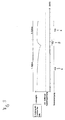
- Figures 2 and 3 show a first and a second embodiment of such a charge control, in which the charge takes place as a function of the state of charge or the time.
- the graph shows the state of charge of the electrical energy storage device 3, which can be determined, for example, based on the voltage provided by the energy storage, as a function of time.
- Below the diagram is also indicated whether the door drive is connected to the mains supply or not, ie whether the door drive in the first operating mode 6, in which the drive is disconnected from the mains supply and the electrical energy is provided by the electrical energy storage, or in the second operating mode 7, during which the door drive is connected to the mains supply 1.
- the charging control takes place while the charge as a function of state of charge. If the charge of the energy store falls below a switch-on threshold, the charge controller automatically switches from the first operating mode 6 into the second operating mode 7 by connecting the door drive according to the invention to the grid. As a result, the electrical energy storage is charged via the mains supply 1. If the electrical energy store is charged, the charge controller switches back to the first operating mode and disconnects the door drive according to the invention from the mains supply, so that the electrical energy is again made available by the electrical energy store, which thereby discharges again.
- Typical charging cycles thus consist of a long operating time in the first operating mode 6, which is followed by a short operating time in the second operating mode 7. Switches the controller regardless of the actual charge control in the second mode of operation, since the drive motor 10 is to be moved, the energy storage is also charged, thereby starting a new cycle.
- FIG. 3 now shows an alternative embodiment of the charging controller according to the invention, in which the charge takes place as a function of time. Since the maximum energy requirement in the inactive mode is known, the minimum time can be determined without recharging the energy storage. Will be the second during this time Operating mode, in which the energy storage is recharged, not already activated due to an operation of the drive motor 10, so the charging control switches to recharge in the second operating mode. This also makes it possible to ensure that the system voltage provided by the energy store does not fall below a minimum permissible system voltage.
- the power consumption of the door drive according to the invention over the period of one year can be reduced to approximately one tenth of the amount of energy usually required. This results in a significant energy cost savings and improved environmental protection.
- the integrated energy storage of the present invention can be optimally designed in its efficiency to the inactive mode, which is much more efficient during the inactive operating times than the power supply by a power supply.
- the energy storage device is then charged during the active operating cycles during which the drive motor 10 is moved and the door drive according to the invention is in any case connected to the mains supply. If this is insufficient, since the door drive is not activated often enough, the charging control according to the invention intervenes, which, if necessary, recharges the electrical energy store via the mains supply.
Abstract
Description
Die vorliegende Erfindung betrifft einen Torantrieb mit elektrisch betriebenen Komponenten, welche über einen Netzanschluß mit elektrischer Energie versorgt werden. Üblicherweise weist der Torantrieb dabei eine elektronische Steuerung sowie einen elektrischen Antriebsmotor auf, welche zu ihrem Betrieb elektrische Energie benötigen.The present invention relates to a door drive with electrically operated components, which are supplied via a network connection with electrical energy. Usually, the door drive has an electronic control and an electric drive motor, which require electrical energy for their operation.
Der Antrieb und dessen Steuerung sind bei bekannten Antrieben üblicherweise permanent mit dem Stromnetz verbunden, so dass ständig Leistung aufgenommen wird. Insbesondere wenn ein Transformator zum Einsatz kommt, um sowohl den Elektromotor als auch die Steuerung mit elektrischer Energie zu versorgen, ist dieser jedoch auf die Leistungsaufnahme während der Betriebszeiten des Elektromotors ausgelegt. Wird der Elektromotor nicht betrieben, wird damit häufig Energie verschwendet.The drive and its control are usually permanently connected to the power supply in known drives, so that power is constantly being absorbed. In particular, when a transformer is used to supply both the electric motor and the controller with electrical energy, but this is designed for the power consumption during the operating times of the electric motor. If the electric motor is not operated, energy is often wasted.
Die aktiven Betriebszeiten von Torantrieben, d.h. die Betriebszeiten des Elektromotors des Antriebs, betragen aber fast immer nur wenige Minuten, wobei ein Öffnungszyklus häufig auch nur zwanzig Sekunden benötigt. Während der übrigen inaktiven Betriebszeiten wird dagegen lediglich elektrische Energie für die Steuerung benötigt, während der erheblich größere Energieverbrauch für den Antriebsmotor wegfällt.The active operating times of gate drives, ie the operating times of the electric motor of the drive, but almost always only a few minutes, with an opening cycle often requires only twenty seconds. During the remaining inactive operating times, however, only electrical energy for the controller needed while the significantly greater energy consumption for the drive motor is eliminated.
Zur Reduzierung der Energieverluste während der inaktiven Betriebsphasen werden häufig zwei Transformatoren, einer für den inaktiven Modus und ein zweiter zuschaltbarer für den aktiven Betriebsmodus eingesetzt. Als Sonderform kann auch wie in
Solche Lösungen sind jedoch konstruktiv aufwendig und können den Energieverbrauch während der inaktiven Betriebsphasen dennoch nicht auf ein zufriedenstellendes Niveau senken.However, such solutions are structurally complex and can not reduce the energy consumption during the inactive operating phases yet to a satisfactory level.
Aufgabe der vorliegenden Erfindung ist es daher, einen Torantrieb mit reduziertem Energieverbrauch insbesondere während der inaktiven Betriebszeiten zur Verfügung zu stellen. Vorteilhafterweise soll dies auf einfache und kostengünstige Weise gelöst werden.The object of the present invention is therefore to provide a door drive with reduced energy consumption, in particular during inactive operating times. Advantageously, this should be solved in a simple and cost-effective manner.
Erfindungsgemäß wird diese Aufgabe von einem Torantrieb gemäß Anspruch 1 gelöst. Ein solcher Torantrieb mit elektrisch betriebenen Komponenten, welche über einen Netzanschluß mit elektrischer Energie versorgt werden, weist erfindungsgemäß eine Steuerung und einen elektrischen Energiespeicher auf, wobei in einem ersten Betriebsmodus die Steuerung den Torantrieb vom Netz trennt und der elektrische Energiespeicher die elektrische Energie bereitstellt und in einem zweiten Betriebsmodus die Steuerung den Torantrieb mit dem Netz verbindet. Erfindungsgemäß läßt sich so die Leistungsaufnahme des Torantriebs nochmals erheblich vermindern, wobei Messungen gegenüber herkömmlichen Lösungen mit zwei Transformatoren eine Reduktion auf ein Zehntel des üblicherweise benötigten Jahresverbrauchs an Energie belegen.According to the invention, this object is achieved by a door drive according to
Durch den integrierten Energiespeicher besteht dabei nämlich die Möglichkeit, den Antrieb zeitweise komplett vom Stromnetz zu trennen. Während dieser Zeit wird keine Energie aus dem Stromnetz benötigt, da diese von dem Energiespeicher zur Verfügung gestellt wird. Der integrierte Energiespeicher kann dabei optimal auf den inaktiven Modus ausgelegt werden, und zwar mit einem sehr viel besseren Wirkungsgrad als ein Netzteil.Because of the integrated energy storage, it is possible to temporarily disconnect the drive completely from the power grid. During this time will be no energy from the power grid needed, as it is provided by the energy storage. The integrated energy storage can be optimally designed for the inactive mode, with a much better efficiency than a power supply.
Weiterhin vorteilhafterweise wird dabei der Torantrieb in Phasen, in welchen der Antriebsmotor nicht bewegt wird, im ersten Betriebsmodus betrieben. Der erste Betriebsmodus entspricht damit dem inaktiven Betriebsmodus des Torantriebs, bei welchem lediglich die Steuerung mit Energie versorgt werden muß, nicht aber der Antriebsmotor, da das Tor nicht bewegt wird. Der in dieser Phase sehr viel kleinere Energieverbrauch kann nun problemlos durch den elektrischen Energiespeicher bereitgestellt werden, ohne dass der Torantrieb mit dem Netz verbunden sein müßte.Furthermore advantageously, the door drive is operated in phases in which the drive motor is not moved in the first operating mode. The first operating mode thus corresponds to the inactive operating mode of the door drive, in which only the controller must be supplied with energy, but not the drive motor, since the gate is not moved. The much smaller energy consumption in this phase can now be easily provided by the electrical energy storage, without the door drive would have to be connected to the network.
Weiterhin vorteilhafterweise schaltet die Steuerung in den zweiten Betriebsmodus, wenn der Antriebsmotor bewegt wird. So kann der erheblich größere Energieverbrauch des Antriebsmotors über den Netzanschluß bereit gestellt werden.Further advantageously, the controller switches to the second operating mode when the drive motor is being moved. Thus, the much greater power consumption of the drive motor can be provided via the power supply.
Weiterhin vorteilhafterweise wird der elektrische Energiespeicher dabei im zweiten Betriebsmodus aufgeladen. Der Energiespeicher kann damit während der Betriebszyklen des Antriebsmotors, während welchen der Torantrieb ohnehin mit dem Netz verbunden ist, aufgeladen werden.Further advantageously, the electrical energy store is charged in the second operating mode. The energy storage can thus be charged during the operating cycles of the drive motor, during which the door drive is already connected to the network anyway.
Weiterhin vorteilhafterweise weist der Torantrieb zudem eine Ladesteuerung auf, welche unabhängig vom Betriebszustand des Antriebsmotors in den zweiten Betriebsmodus schaltet, um den elektrischen Energiespeicher aufzuladen. Hierdurch kann der Energiespeicher kurzfristig nachgeladen werden; wenn die aktiven Betriebsphasen des Torantriebs für die Ladung des Energiespeichers nicht ausreichen. Die Ladesteuerung schaltet dann in den zweiten Betriebsmodus, in welchem der Torantrieb mit dem Netz verbunden ist, und lädt den Energiespeicher auf.Further advantageously, the door drive also has a charging control, which switches independently of the operating state of the drive motor in the second operating mode to charge the electrical energy storage. As a result, the energy storage can be recharged at short notice; if the active operating phases of the door drive are insufficient for charging the energy store. The charging controller then switches to the second operating mode, in which the door drive is connected to the mains, and charges the energy store.
Vorteilhafterweise schaltet die Ladesteuerung dabei in Abhängigkeit vom Ladezustand des elektrischen Energiespeichers in den zweiten Betriebsmodus. Die Ladesteuerung umfaßt also eine Überwachung des Ladezustands des Energiespeichers und lädt diesen nach, wenn der Ladezustand unter einen gewissen Wert gefallen ist. Das Laden des elektrischen Energiespeichers erfolgt damit als Funktion des Ladezustandes.Advantageously, the charge controller switches in dependence on the state of charge of the electrical energy storage in the second operating mode. The charging control thus includes a monitoring of the state of charge of the energy storage and recharges this when the state of charge has fallen below a certain value. The charging of the electrical energy storage is thus carried out as a function of the state of charge.
Alternativ kann die Ladesteuerung auch in Abhängigkeit von der seit dem letzten Ladezyklus verstrichenen Zeitspanne in den zweiten Betriebsmodus schalten. Da der maximale Energiebedarf im inaktiven Betrieb bekannt ist (worst case), läßt sich die minimale Zeitdauer ohne Nachladen des Energiespeichers bestimmen. Wird während dieser Zeit nicht ohnehin in den zweiten Betriebsmodus geschaltet, weil der Antriebmotor bewegt wird, so schaltet die Ladesteuerung nach Ablauf dieser Zeitspanne unabhängig vom Betriebszustand des Antriebsmotors in den zweiten Betriebsmodus, um den Energiespeicher nachzuladen. Das Laden des elektrischen Energiespeichers erfolgt damit als Funktion der Zeit.Alternatively, the charge control may also switch to the second operating mode depending on the time elapsed since the last charge cycle. Since the maximum energy requirement in inactive operation is known (worst case), the minimum time can be determined without recharging the energy storage. If not switched to the second operating mode during this time, because the drive motor is moved, the charging control switches after this time, regardless of the operating state of the drive motor in the second operating mode to recharge the energy storage. The charging of the electrical energy storage is done as a function of time.
Weiterhin vorteilhafterweise weist der erfindungsgemäße Torantrieb ein Netzteil auf, welches mit dem Netzanschluß verbunden oder vom Netzanschluß getrennt wird, um von einem Betriebsmodus in den anderen Betriebsmodus zu schalten. Gerade für solche Torantriebe, bei welchen die elektrisch betriebenen Komponenten über ein Netzteil mit elektrischer Energie versorgt werden, ergibt die erfindungsgemäße Steuerung eine besonders große Energieeinsparung, da das Netzteil in seinem Wirkungsgrad wesentlich schlechter auf die inaktiven Betriebsphasen ausgelegt werden kann als die erfindungsgemäße Steuerung mit dem elektrischen Energiespeicher.Further advantageously, the door drive according to the invention comprises a power supply, which is connected to the power supply or disconnected from the power supply to switch from one operating mode to the other operating mode. Especially for such door drives, in which the electrically operated components are supplied via a power supply with electrical energy, the control of the invention results in a particularly large energy savings, since the power supply can be designed significantly inferior in its efficiency to the inactive operating phases as the inventive control with the electrical energy storage.
Weiterhin vorteilhafterweise kommt die erfindungsgemäße Steuerung dabei bei einem Torantrieb zum Einsatz, welcher einen elektrischen Antriebsmotor aufweist, der von dem Netzteil mit elektrischer Energie versorgt wird. Das Netzteil muß bei solchen Antrieben während der aktiven Betriebsphasen, in welchen der Antriebsmotor bewegt wird, sehr viel elektrische Energie zur Verfügung stellen, und in inaktiven Betriebsphasen, in welchen der Antriebsmotor nicht bewegt wird, nur sehr wenig. Die erfindungsgemäße Steuerung mit dem elektrischen Energiespeicher kann hier gegenüber dem Stand der Technik eine enorme Reduktion des Energieverbrauchs bewirken.Further advantageously, the control according to the invention is used in a door drive which has an electric drive motor which is supplied with electrical energy by the power supply. In such drives, the power supply must provide a great deal of electrical energy during active operating phases in which the drive motor is moved, and inactive ones Operating phases in which the drive motor is not moved, only very little. The control according to the invention with the electrical energy storage device can bring about a huge reduction in energy consumption compared to the prior art.
Die vorliegende Erfindung wird nun anhand von Ausführungsbeispielen und Zeichnungen näher dargestellt.The present invention will now be described in more detail with reference to embodiments and drawings.
- Figur 1FIG. 1
- eine Prinzipdarstellung eines Ausführungsbeispiels des erfindungsge- mäßen Torantriebs,a schematic diagram of an embodiment of the inventive gate drive,
- Figur 2FIG. 2
- ein erstes Ausführungsbeispiel einer erfindungsgemäßen Ladungssteue- rung, unda first embodiment of a charge control according to the invention, and
- Figur 3FIG. 3
- ein zweites Ausführungsbeispiel einer erfindungsgemäßen Ladungs- steuerung.A second embodiment of a charge control according to the invention.
Dabei ist ein Transformator 5 vorgesehen, welcher über einen Schalter 4 mit der Netzversorgung 1 verbunden bzw. von der Netzversorgung 1 getrennt werden kann. Der Transformator 5 stellt dabei die elektrische Energie zur Verfügung, mit welcher die Steuerung 2 und der Antriebsmotor 10 betrieben werden. Der Transformator ist deshalb auf die Leistungsaufnahme während der aktiven Betriebsphasen des Torantriebs ausgelegt, während welcher der Antriebsmotor 10 das Tor bewegt.In this case, a
Um während inaktiver Betriebsphasen, währen welcher der Antriebsmotor 10 nicht bewegt wird und damit die Leistungsaufnahme des gesamten Systems erheblich niedriger liegt als die Leistungsaufnahme, auf welche der Transformator 5 ausgelegt ist, ist ein Energiespeicher 3 vorgesehen. Die Steuerung 2 trennt nun in inaktiven Phasen durch Ansteuerung des Schalters 4 den Transformator 5 vom Netz, so dass der gesamte Torantrieb von der Netzversorgung komplett getrennt ist. Während dieses ersten Betriebsmodus wird die elektrische Energie für die Steuerung über den Energiespeicher 3 zur Verfügung gestellt. Als Energiespeicher kann z.B. ein Akkumulator oder ein Kondensator verwendet werden kann.In order during inactive operating phases, during which the
Die Steuerung 2 kann nun von diesem ersten Betriebsmodus in einen zweiten Betriebsmodus schalten, indem sie den Schalter 4 schließt und so den Transformator 5 mit der Netzversorgung 1 verbindet. Insbesondere schaltet die Steuerung 2 in diesen zweiten Betriebsmodus, wenn der Antriebsmotor 10 bewegt werden soll, um die dann erheblich höhere Leistungsaufnahme über die Netzversorgung 1 zur Verfügung zu stellen.The
Der Energiespeicher 3 ist dagegen auf den inaktiven Betrieb ausgelegt, während welchem der Antriebsmotor 10 nicht bewegt wird, so dass nur die Steuerung 2 mit Energie versorgt werden muß. Während des ersten Betriebsmodus wird damit die elektrische Energie vom Energiespeicher bereitgestellt, welcher sich hierdurch entlädt. Schaltet die Steuerung dagegen in den zweiten Betriebsmodus, weil das Tor durch den Antriebsmotor 10 bewegt werden soll, wird gleichzeitig der Energiespeicher 3 über die von der Netzversorgung 1 zur Verfügung gestellte elektrische Energie aufgeladen.The
Die erfindungsgemäße Steuerung 2 weist weiterhin eine Ladesteuerung auf, welche unabhängig vom Betriebszustand des Antriebsmotors 10 in den zweiten Betriebsmodus schaltet, um den elektrischen Energiespeicher aufzuladen. Hierdurch wird sichergestellt, dass der Energiespeicher auch dann geladen wird, wenn der Antriebsmotor 10 über lange Betriebszeiten nicht bewegt wird.The
In
Bei dem in
Durch die komplette Trennung des erfindungsgemäßen Torantriebs vom Stromnetz während eines Großteils der Betriebszeit läßt sich dabei die Leistungsaufnahme des erfindungsgemäßen Torantriebs über den Zeitraum eines Jahres betrachtet auf ca. ein Zehntel der üblicherweise benötigten Energiemenge reduzieren. Hierdurch ergibt sich eine erhebliche Energiekostenersparnis und ein verbesserter Umweltschutz.As a result of the complete separation of the door drive according to the invention from the power supply during a large part of the operating time, the power consumption of the door drive according to the invention over the period of one year can be reduced to approximately one tenth of the amount of energy usually required. This results in a significant energy cost savings and improved environmental protection.
Der integrierte Energiespeicher der vorliegenden Erfindung kann dabei in seinem Wirkungsgrad optimal auf den inaktiven Modus ausgelegt werden, was während der inaktiven Betriebszeiten sehr viel effizienter ist als die Energieversorgung durch ein Netzteil. Der Energiespeicher wird dann während der aktiven Betriebszyklen, während welcher der Antriebsmotor 10 bewegt wird und der erfindungsgemäße Torantrieb ohnehin mit der Netzversorgung verbunden ist, geladen. Reicht dies nicht aus, da der Torantrieb nicht oft genug aktiviert wird, greift die erfindungsgemäße Ladesteuerung ein, welche wenn nötig den elektrischen Energiespeicher über die Netzversorgung nachlädt.The integrated energy storage of the present invention can be optimally designed in its efficiency to the inactive mode, which is much more efficient during the inactive operating times than the power supply by a power supply. The energy storage device is then charged during the active operating cycles during which the
Claims (9)
dadurch gekennzeichnet,
dass eine Steuerung (2) und ein elektrischer Energiespeicher (3) vorgesehen sind, wobei in einem ersten Betriebsmodus (6) die Steuerung (2) den Torantrieb vom Netz (1) trennt und der elektrische Energiespeicher (3) die elektrische Energie bereitstellt und in einem zweiten Betriebsmodus (7) die Steuerung den Torantrieb mit dem Netz (1) verbindet.Door drive with electrically operated components (2, 10) which are supplied with electrical energy via a mains connection (1),
characterized,
that a control unit (2) and an electrical energy store (3) are provided, wherein in a first operating mode (6), the controller (2) separates the gate drive from the mains (1) and the electrical energy accumulator (3) provides the electrical energy, and in a second operating mode (7), the controller connects the door drive with the network (1).
Applications Claiming Priority (1)
| Application Number | Priority Date | Filing Date | Title |
|---|---|---|---|
| DE202007014555U DE202007014555U1 (en) | 2007-10-17 | 2007-10-17 | door drive |
Publications (3)
| Publication Number | Publication Date |
|---|---|
| EP2050910A2 true EP2050910A2 (en) | 2009-04-22 |
| EP2050910A3 EP2050910A3 (en) | 2011-08-17 |
| EP2050910B1 EP2050910B1 (en) | 2018-12-05 |
Family
ID=40076321
Family Applications (1)
| Application Number | Title | Priority Date | Filing Date |
|---|---|---|---|
| EP08014007.2A Active EP2050910B1 (en) | 2007-10-17 | 2008-08-05 | Door drive |
Country Status (4)
| Country | Link |
|---|---|
| US (1) | US8493015B2 (en) |
| EP (1) | EP2050910B1 (en) |
| CN (1) | CN101413370A (en) |
| DE (1) | DE202007014555U1 (en) |
Cited By (2)
| Publication number | Priority date | Publication date | Assignee | Title |
|---|---|---|---|---|
| DE202009016303U1 (en) | 2009-12-01 | 2011-04-07 | Hörmann KG Antriebstechnik | door drive |
| WO2011085761A3 (en) * | 2010-01-18 | 2011-09-15 | Sommer Antriebs- Und Funktechnik Gmbh | Drive system for a door |
Families Citing this family (1)
| Publication number | Priority date | Publication date | Assignee | Title |
|---|---|---|---|---|
| DE202009014334U1 (en) * | 2009-10-23 | 2011-02-24 | Marantec Antriebs- Und Steuerungstechnik Gmbh & Co. Kg | Transformer device for door drive and door drive |
Citations (2)
| Publication number | Priority date | Publication date | Assignee | Title |
|---|---|---|---|---|
| EP0625626A1 (en) | 1993-05-18 | 1994-11-23 | Marantec Antriebs- Und Steuerungstechnik Gmbh & Co., Produktions Kg | Electric drive unit for a door wing |
| DE19641592A1 (en) | 1996-10-09 | 1998-04-16 | Geze Gmbh & Co | Automatic door drive with mains and auxiliary battery |
Family Cites Families (15)
| Publication number | Priority date | Publication date | Assignee | Title |
|---|---|---|---|---|
| JP3465735B2 (en) * | 1995-10-02 | 2003-11-10 | 株式会社大井製作所 | Automatic opening and closing control of sliding doors for vehicles |
| CA2269001C (en) * | 1998-04-21 | 2008-07-15 | The Chamberlain Group, Inc. | Controller for a door operator |
| US6597138B2 (en) * | 2001-08-01 | 2003-07-22 | The Chamberlain Group, Inc. | Method and apparatus for controlling power supplied to a motor |
| US6670725B2 (en) * | 2001-11-13 | 2003-12-30 | The Chamberlain Group, Inc. | Power apparatus for intermittently powered equipment |
| CN100352131C (en) * | 2002-02-27 | 2007-11-28 | 株式会社日立制作所 | Power-supply system |
| US7755223B2 (en) * | 2002-08-23 | 2010-07-13 | The Chamberlain Group, Inc. | Movable barrier operator with energy management control and corresponding method |
| US6920718B2 (en) * | 2003-04-03 | 2005-07-26 | The Chamberlain Group, Inc. | Independent backup power supply for a security barrier |
| WO2005021914A1 (en) * | 2003-09-03 | 2005-03-10 | Dpnkd Holdings Inc. | Automatic portable door operating system |
| US7786619B2 (en) * | 2003-09-12 | 2010-08-31 | The Chamberlain Group, Inc. | DC power backup |
| CN2733709Y (en) * | 2004-05-31 | 2005-10-12 | 四川长虹电器股份有限公司 | Switching power supply apparatus |
| DE102004037933B3 (en) * | 2004-08-04 | 2006-02-09 | Novoferm Tormatic Gmbh | Garage door drive has electric motor and control unit operated by hand held radio remote unit and mains and battery power supplies |
| US7208897B2 (en) * | 2005-03-04 | 2007-04-24 | Linear Corporation | Motion control system for barrier drive |
| US7266962B2 (en) * | 2005-05-17 | 2007-09-11 | Whirlpool Corporation | Battery supplemented refrigerator and method for using same |
| US7382063B2 (en) * | 2005-05-24 | 2008-06-03 | Wayne-Dalton Corp. | Uninterruptible power source for a barrier operator and related methods |
| DE102005054693B4 (en) * | 2005-11-16 | 2014-09-18 | Georg Ludwig Kunz | Control system for driving a gate or a door |
-
2007
- 2007-10-17 DE DE202007014555U patent/DE202007014555U1/en not_active Expired - Lifetime
-
2008
- 2008-08-05 EP EP08014007.2A patent/EP2050910B1/en active Active
- 2008-10-16 US US12/288,130 patent/US8493015B2/en active Active
- 2008-10-17 CN CNA2008101705409A patent/CN101413370A/en active Pending
Patent Citations (2)
| Publication number | Priority date | Publication date | Assignee | Title |
|---|---|---|---|---|
| EP0625626A1 (en) | 1993-05-18 | 1994-11-23 | Marantec Antriebs- Und Steuerungstechnik Gmbh & Co., Produktions Kg | Electric drive unit for a door wing |
| DE19641592A1 (en) | 1996-10-09 | 1998-04-16 | Geze Gmbh & Co | Automatic door drive with mains and auxiliary battery |
Cited By (4)
| Publication number | Priority date | Publication date | Assignee | Title |
|---|---|---|---|---|
| DE202009016303U1 (en) | 2009-12-01 | 2011-04-07 | Hörmann KG Antriebstechnik | door drive |
| WO2011067087A1 (en) | 2009-12-01 | 2011-06-09 | Hörmann KG Antriebstechnik | Gate drive device |
| DE112010004625B4 (en) * | 2009-12-01 | 2016-06-09 | Hörmann KG Antriebstechnik | door drive |
| WO2011085761A3 (en) * | 2010-01-18 | 2011-09-15 | Sommer Antriebs- Und Funktechnik Gmbh | Drive system for a door |
Also Published As
| Publication number | Publication date |
|---|---|
| US20090140675A1 (en) | 2009-06-04 |
| DE202007014555U1 (en) | 2008-11-27 |
| EP2050910B1 (en) | 2018-12-05 |
| CN101413370A (en) | 2009-04-22 |
| EP2050910A3 (en) | 2011-08-17 |
| US8493015B2 (en) | 2013-07-23 |
Similar Documents
| Publication | Publication Date | Title |
|---|---|---|
| EP3479455B1 (en) | Energy storage device for a motor vehicle | |
| WO2002087068A1 (en) | Device for power supply in a multi-voltage electric system of a motor vehicle | |
| DE102017207102A1 (en) | Stationary storage for temporary storage of electrical energy in an electrical supply network and operating method and retrofit module for the stationary storage | |
| DE102005014285A1 (en) | Apparatus and method for charge equalization of arranged in series individual cells of an energy storage | |
| AT510025B1 (en) | DRIVE UNIT OF AN ELECTRIC VEHICLE | |
| DE102015011230A1 (en) | Energy storage device for an electrical alternating voltage network | |
| DE102010042328A1 (en) | Method for monitoring the charging operation of an energy storage device in a vehicle and charging system for charging an energy storage device in a vehicle | |
| EP3024130A1 (en) | DC/DC converter | |
| EP2941363B1 (en) | Supplying electric traction motors of a rail vehicle with electrical energy using a plurality of internal combustion engines | |
| EP3634803B1 (en) | Power supply for a rail vehicle | |
| WO2016041711A1 (en) | Electrical system for a vehicle which can be electrically driven | |
| DE102012007158A1 (en) | Device for controlling power flow in motor vehicle e.g. motor car, has switching device that separates electric drive from bidirectionally operable inverter and connects inverter with charging terminal device based on control signal | |
| EP2050910B1 (en) | Door drive | |
| EP2994339B1 (en) | High voltage on-board network structure for vehicles | |
| DE102011076787A1 (en) | power supply | |
| EP3027462A1 (en) | Energy storage arrangement, energy storage system and method for operating an energy storage arrangement | |
| DE102017201657A1 (en) | Circuit arrangement, electrical system and means of transport with improved DC link charging | |
| EP3811509B1 (en) | Photovoltaic inverter and method for operating the same | |
| DE10057113B4 (en) | Energy supply arrangement for smoke and heat extraction systems with electric drives | |
| DE102019123403A1 (en) | Method for operating a high-voltage battery, control device, on-board network and motor vehicle | |
| DE112010001155T5 (en) | Control system for a single-phase induction motor and control method for a single-phase induction motor | |
| EP2229719B1 (en) | Circuit configuration for operating a household appliance | |
| DE102020130539B4 (en) | Method for operating an energy supply system, energy supply system and control unit for an energy supply system | |
| DE10159645B4 (en) | Method and device for maintaining a supply voltage of a power supply electronics of a matrix converter in case of power failure | |
| DE102016005079A1 (en) | Device and method for mains current storage and stand-alone grid generation with shared switching elements for half-wave polarity switching |
Legal Events
| Date | Code | Title | Description |
|---|---|---|---|
| PUAI | Public reference made under article 153(3) epc to a published international application that has entered the european phase |
Free format text: ORIGINAL CODE: 0009012 |
|
| 17P | Request for examination filed |
Effective date: 20081103 |
|
| AK | Designated contracting states |
Kind code of ref document: A2 Designated state(s): AT BE BG CH CY CZ DE DK EE ES FI FR GB GR HR HU IE IS IT LI LT LU LV MC MT NL NO PL PT RO SE SI SK TR |
|
| AX | Request for extension of the european patent |
Extension state: AL BA MK RS |
|
| PUAL | Search report despatched |
Free format text: ORIGINAL CODE: 0009013 |
|
| AK | Designated contracting states |
Kind code of ref document: A3 Designated state(s): AT BE BG CH CY CZ DE DK EE ES FI FR GB GR HR HU IE IS IT LI LT LU LV MC MT NL NO PL PT RO SE SI SK TR |
|
| AX | Request for extension of the european patent |
Extension state: AL BA MK RS |
|
| RIC1 | Information provided on ipc code assigned before grant |
Ipc: E05F 15/10 20060101AFI20110711BHEP Ipc: E05F 15/16 20060101ALI20110711BHEP |
|
| AKX | Designation fees paid |
Designated state(s): DE ES FR GB IT |
|
| 17Q | First examination report despatched |
Effective date: 20130311 |
|
| REG | Reference to a national code |
Ref country code: DE Ref legal event code: R079 Ref document number: 502008016497 Country of ref document: DE Free format text: PREVIOUS MAIN CLASS: E05F0015100000 Ipc: E05F0015600000 |
|
| GRAP | Despatch of communication of intention to grant a patent |
Free format text: ORIGINAL CODE: EPIDOSNIGR1 |
|
| STAA | Information on the status of an ep patent application or granted ep patent |
Free format text: STATUS: GRANT OF PATENT IS INTENDED |
|
| RIC1 | Information provided on ipc code assigned before grant |
Ipc: E05F 15/60 20150101AFI20180524BHEP |
|
| INTG | Intention to grant announced |
Effective date: 20180625 |
|
| GRAS | Grant fee paid |
Free format text: ORIGINAL CODE: EPIDOSNIGR3 |
|
| GRAA | (expected) grant |
Free format text: ORIGINAL CODE: 0009210 |
|
| GRAA | (expected) grant |
Free format text: ORIGINAL CODE: 0009210 |
|
| STAA | Information on the status of an ep patent application or granted ep patent |
Free format text: STATUS: THE PATENT HAS BEEN GRANTED |
|
| AK | Designated contracting states |
Kind code of ref document: B1 Designated state(s): DE ES FR GB IT |
|
| REG | Reference to a national code |
Ref country code: GB Ref legal event code: FG4D Free format text: NOT ENGLISH |
|
| REG | Reference to a national code |
Ref country code: DE Ref legal event code: R096 Ref document number: 502008016497 Country of ref document: DE |
|
| PG25 | Lapsed in a contracting state [announced via postgrant information from national office to epo] |
Ref country code: ES Free format text: LAPSE BECAUSE OF FAILURE TO SUBMIT A TRANSLATION OF THE DESCRIPTION OR TO PAY THE FEE WITHIN THE PRESCRIBED TIME-LIMIT Effective date: 20181205 |
|
| REG | Reference to a national code |
Ref country code: DE Ref legal event code: R097 Ref document number: 502008016497 Country of ref document: DE |
|
| PLBE | No opposition filed within time limit |
Free format text: ORIGINAL CODE: 0009261 |
|
| STAA | Information on the status of an ep patent application or granted ep patent |
Free format text: STATUS: NO OPPOSITION FILED WITHIN TIME LIMIT |
|
| 26N | No opposition filed |
Effective date: 20190906 |
|
| PGFP | Annual fee paid to national office [announced via postgrant information from national office to epo] |
Ref country code: IT Payment date: 20230829 Year of fee payment: 16 Ref country code: GB Payment date: 20230824 Year of fee payment: 16 |
|
| PGFP | Annual fee paid to national office [announced via postgrant information from national office to epo] |
Ref country code: FR Payment date: 20230824 Year of fee payment: 16 Ref country code: DE Payment date: 20230830 Year of fee payment: 16 |