EP2050654A1 - Electric power steering system - Google Patents
Electric power steering system Download PDFInfo
- Publication number
- EP2050654A1 EP2050654A1 EP07791649A EP07791649A EP2050654A1 EP 2050654 A1 EP2050654 A1 EP 2050654A1 EP 07791649 A EP07791649 A EP 07791649A EP 07791649 A EP07791649 A EP 07791649A EP 2050654 A1 EP2050654 A1 EP 2050654A1
- Authority
- EP
- European Patent Office
- Prior art keywords
- gear box
- reduction gear
- electric motor
- control unit
- unit
- Prior art date
- Legal status (The legal status is an assumption and is not a legal conclusion. Google has not performed a legal analysis and makes no representation as to the accuracy of the status listed.)
- Withdrawn
Links
Images











Classifications
-
- B—PERFORMING OPERATIONS; TRANSPORTING
- B62—LAND VEHICLES FOR TRAVELLING OTHERWISE THAN ON RAILS
- B62D—MOTOR VEHICLES; TRAILERS
- B62D5/00—Power-assisted or power-driven steering
- B62D5/04—Power-assisted or power-driven steering electrical, e.g. using an electric servo-motor connected to, or forming part of, the steering gear
- B62D5/0403—Power-assisted or power-driven steering electrical, e.g. using an electric servo-motor connected to, or forming part of, the steering gear characterised by constructional features, e.g. common housing for motor and gear box
- B62D5/0406—Power-assisted or power-driven steering electrical, e.g. using an electric servo-motor connected to, or forming part of, the steering gear characterised by constructional features, e.g. common housing for motor and gear box including housing for electronic control unit
-
- H—ELECTRICITY
- H02—GENERATION; CONVERSION OR DISTRIBUTION OF ELECTRIC POWER
- H02K—DYNAMO-ELECTRIC MACHINES
- H02K11/00—Structural association of dynamo-electric machines with electric components or with devices for shielding, monitoring or protection
- H02K11/30—Structural association with control circuits or drive circuits
- H02K11/33—Drive circuits, e.g. power electronics
-
- H—ELECTRICITY
- H02—GENERATION; CONVERSION OR DISTRIBUTION OF ELECTRIC POWER
- H02K—DYNAMO-ELECTRIC MACHINES
- H02K7/00—Arrangements for handling mechanical energy structurally associated with dynamo-electric machines, e.g. structural association with mechanical driving motors or auxiliary dynamo-electric machines
- H02K7/10—Structural association with clutches, brakes, gears, pulleys or mechanical starters
- H02K7/116—Structural association with clutches, brakes, gears, pulleys or mechanical starters with gears
- H02K7/1163—Structural association with clutches, brakes, gears, pulleys or mechanical starters with gears where at least two gears have non-parallel axes without having orbital motion
- H02K7/1166—Structural association with clutches, brakes, gears, pulleys or mechanical starters with gears where at least two gears have non-parallel axes without having orbital motion comprising worm and worm-wheel
-
- H—ELECTRICITY
- H02—GENERATION; CONVERSION OR DISTRIBUTION OF ELECTRIC POWER
- H02K—DYNAMO-ELECTRIC MACHINES
- H02K5/00—Casings; Enclosures; Supports
- H02K5/04—Casings or enclosures characterised by the shape, form or construction thereof
- H02K5/22—Auxiliary parts of casings not covered by groups H02K5/06-H02K5/20, e.g. shaped to form connection boxes or terminal boxes
- H02K5/225—Terminal boxes or connection arrangements
-
- H—ELECTRICITY
- H02—GENERATION; CONVERSION OR DISTRIBUTION OF ELECTRIC POWER
- H02K—DYNAMO-ELECTRIC MACHINES
- H02K7/00—Arrangements for handling mechanical energy structurally associated with dynamo-electric machines, e.g. structural association with mechanical driving motors or auxiliary dynamo-electric machines
- H02K7/06—Means for converting reciprocating motion into rotary motion or vice versa
Definitions
- the present invention relates to an electric power steering apparatus including a steering column having inserted therein a steering shaft to which steering torque is transmitted and an electric motor that transmits a steering assisting force to the steering column via a reduction mechanism in a reduction gear box.
- a CPU On the control board, a CPU is attached on a front surface side, a capacitor, a power relay, and the like are disposed and a supporting board serving as a heat sink is protrudingly provided on a rear surface side, and an FET (field effect transistor) is attached to this supporting board to configure a bridge circuit, and a plus side of the bridge circuit is connected to a battery serving as a power supply via the power relay and a minus side thereof is earthed.
- FET field effect transistor
- the motor side connection terminal formed in the electric motor is connected to the board side connection terminal formed on the control board, a torque sensor and a connector formed on the control board are connected by a signal line, the plus side of the bridge circuit including four FETs disposed on the control board is connected to the battery and the minus side thereof is earthed.
- the minus side of the bridge circuit since it is necessary to connect an earth line to a vehicle body side member, this is bothersome and causes an earth failure.
- a torque sensor including a magnetic sensor is incorporated in a column housing and a signal terminal of this torque sensor is directly connected to a control board to omit a signal line.
- the torque sensor including the magnetic sensor is incorporated in the column housing, it is necessary to ground the torque sensor to a vehicle body side using a ground harness exclusive for the column housing in order to improve EMC (electromagnetic compatibility) of a circuit system of the torque sensor.
- the ground harness for this purpose is necessary.
- the present invention has been devised in view of the unsolved problems of the examples in the past and it is an object of the present invention to provide an electric power steering apparatus in which ground processing for respective sections requiring a ground can be reduced to necessary minimum to improve assemblability and a fall in electromagnetic compatibility and fluctuation in control accuracy can be controlled.
- an electric power steering apparatus including a steering column having inserted therein a steering shaft to which steering torque is transmitted and an electric motor that transmits a steering assisting force to the steering shaft via a reduction mechanism in a conductive reduction gear box.
- the electric power steering apparatus is characterized in that a control unit including a control board mounted with a control circuit that controls to drive the electric motor is mounted on the reduction gear box, a connecting section of the electric motor is electrically connected to the control unit directly, and connection of the reduction gear box and the control unit to a ground is performed via a grounding line disposed between the control unit and a power feeding unit.
- an electric power steering apparatus is characterized in that, in the invention according to claim 1, the control unit includes at least a power module board mounted with a power module involving heat generation that controls to drive the electric motor and an insulated frame that surrounds the power module board and includes a unit side connecting section that connects the connecting section of the electric motor and a power supply connector to which the grounding line is connected, the power module board is mounted on a control-unit mounting surface of the reduction gear box, and the grounding line is connected to the reduction gear box via the power module board.
- an electric power steering apparatus is characterized in that, in the invention according to claim 1, the control unit includes at least a board mounted with the control circuit, an insulated frame that surrounds the board and includes a unit side connecting section that connects the connecting section of the electric motor and a power supply connector to which the grounding line is connected, and a conductive cover that covers the control board, the power module board, and the insulated frame, and the grounding line is connected to the reduction gear box via the conductive cover.
- an electric power steering apparatus is characterized in that, in the invention according to claim 3, the board includes a control board mounted with a command-value calculating unit that calculates a driving command value for the electric motor and a power module board mounted with a power module involving heat generation that controls to drive the electric motor on the basis of the driving command value from the command-value calculating unit.
- an electric power steering apparatus is characterized in that, in the invention according to claim 1, the control unit includes at least a control board mounted with a command-value calculating unit that calculates a driving command value for the electric motor, a power module board mounted with a power module involving heat generation that controls to drive the electric motor, and an insulated frame that surrounds the control board and the power module board and includes a unit side connecting section that connects the connecting section of the electric motor and a power supply connector to which the grounding line is connected, the power module board is mounted on a control-unit mounting surface of the reduction gear box, and a first grounding path connected to the reduction gear box via the power module board and a second grounding path connected to the reduction gear box via the conductive cover are formed in parallel between the grounding line and the reduction gear box.
- an electric power steering apparatus is characterized in that, in the invention according to any one of claims 1 to 5, the reduction gear box is made of a highly thermally conductive material.
- an electric power steering apparatus is characterized in that, in the invention according to claim 6, the reduction gear box is formed by die-casting any one of aluminum, an aluminum alloy, magnesium, and a magnesium alloy.
- an electric power steering apparatus is characterized in that, in the invention according to any one of claims 1 to 7, the reduction gear box includes at least a worm housing unit that houses a worm coupled to an output shaft of the electric motor, a worm-wheel housing unit that houses a worm wheel coupled to the steering shaft, and a torque-sensor housing unit that is continuously connected to the worm-wheel housing unit, houses the torque sensor, and is coupled to a steering column, and a control-unit mounting section on which the control unit is mounted is formed in an outer periphery of the worm housing unit, the worm-wheel housing unit, and the torque-sensor housing unit.
- an electric power steering apparatus is characterized in that, in the invention according to claim 8, a distal end of the torque-sensor housing unit is formed as a contraction stopper for the steering column at the time of collapse, and a contraction stopper side end surface position of the control unit mounted on the control-unit mounting section is set further on a worm-wheel housing unit side than the contraction stopper.
- the control unit including the board mounted with the control circuit that controls to drive the electric motor is mounted on the reduction gear box, the connecting section of the electric motor is electrically connected to the control unit directly, and the connection of the reduction gear box and the control unit to the ground is performed via the grounding line disposed between the control unit and the power feeding unit.
- the reduction gear box and the control unit are grounded to the power feeding unit via the common ground line, there is an effect that it is possible to improve electromagnetic compatibility (EMC) of the reduction gear box and it is possible to reduce the number of components and man-hour and improve assemblability of the electric power steering apparatus.
- EMC electromagnetic compatibility
- FIG. 1 is a perspective view showing an example of a case in which a first embodiment of the present invention is applied to a right-hand drive car.
- FIG. 2 is a front view
- FIG. 3 is a left side view
- FIG. 4 is a plan view
- FIGS. 5 and 6 are disassembled perspective views of a main part of the example.
- reference numeral 1 denotes a column-type electric power steering apparatus.
- a reduction gear box 4 is coupled to a steering column 3 in which a steering shaft 2 coupled to a steering wheel (not shown) is inserted rotatably.
- an electric motor 5 including a brush motor, an axial direction of which is extended in a direction orthogonal to an axial direction of the steering column 3, is disposed.
- the steering column 3 has, in a coupling section with the reduction gear box 4, a double tube structure including an inner tube 3a and an outer tube 3b for absorbing impact energy at the time of collapse and securing a predetermined collapse stroke.
- the outer tube 3b of the steering column 3 and the reduction gear box 4 are attached to a vehicle body side by an upper attachment bracket 6 and a lower attachment bracket 7.
- the lower attachment bracket 7 is formed by an attachment plate section 7a attached to a vehicle body side member (not shown) and a pair of supporting plate sections 7b that extend in parallel while keeping a predetermined space with respect to a lower surface of this attachment plate section 7a.
- a distal end of the supporting plate section 7b is pivotally coupled to, via a pivot 7c, a supporting section 4b integrally formed in a cover 4a disposed on a lower end side of the reduction gear box 4, i.e., a vehicle front side.
- the upper attachment bracket 6 includes an attachment plate section 6a attached to the vehicle body side member (not shown), a square frame-shaped supporting section 6b formed integrally with this attachment plate section 6a, and a tilt mechanism 6c, which supports the outer tube 3b of the steering column 3, formed in this square frame-shaped supporting section 6b.
- the attachment plate section 6a includes a pair of left and right capsules 6d attached to the vehicle body side member (not shown) and a sliding plate section 6f fixed to these capsules 6d by a resin injection 6e.
- the steering shaft 2 includes an input shaft 2a, an upper end of which is coupled to the steering wheel (not shown), and an output shaft 2c that is coupled to a lower end of this input shaft 2a via a torsion bar 2b and covers the torsion bar 2b.
- the reduction gear box 4 is formed by, for example, die-casting a material having high heat conductivity and electric conductivity, for example, any one of aluminum, an aluminum alloy, magnesium, and a magnesium alloy.
- This reduction gear box 4 includes a worm housing unit 12 that houses a worm 11 coupled to the output shaft 5a of the electric motor 5, a worm-wheel housing unit 14 that is provided on a lower side of this worm housing unit 12, has a center axis orthogonal to a center axis of the worm housing unit 12, and houses a worm wheel 13 that meshes with the worm 11, a torque-sensor housing unit 16 that is integrally and coaxially coupled to a rear side of this worm-wheel housing unit 14 and houses a torque sensor 15, a motor mounting section 17 that is formed in an open end face of the worm housing unit 12 and to which the electric motor 5 is attached, a column attaching section 18 that is formed in an rear end face of the torque-sensor housing unit 16 and to which an attachment flange 2a formed at a front end of the steering column 3 is attached, and a control-unit mounting section 20 that is formed in a plane orthogonal to a center axis of the worm-wheel housing unit 14 and the torque-sensor housing
- the torque sensor 15 is configured to magnetically detect a twist state between the input shaft 2a and the output shaft 2c of the steering shaft 2 and detect steering torque transmitted to the steering shaft with a pair of detection coils 15a and 15b.
- External connection terminals 15c, 15d, 15e, and 15f which project to the outside in parallel to a direction orthogonal to a center axis of the steering column 3, are connected to starts and ends of winding of these pair of detection coils 15a and 15b, respectively. Projecting portions of these external connection terminals 15c to 15f are bent, in the center thereof, in parallel to the center axis of the steering column 3 and formed in an L shape.
- bus bars 5c and 5d serving as connection terminals connected to a built-in brush are protrudingly formed toward the rear of the vehicle body perpendicular to an axis direction of the electric motor 5 and to be substantially parallel to the center axis of the steering column 3.
- Long holes 5e through which fixing screws are inserted are drilled at distal end portions of these bus bars 5c and 5d. As shown in FIG.
- the respective bus bars 5c and 5d are disposed to be insulated from each other in a brush supporting member 5f made of synthetic resin having an armature insertion hole in the center of a bottom portion thereof.
- the bus bars 5c and 5d include arcuate conductor sections 5i and 5j separately connected to two pairs of brushes 5g and 5h and terminal sections 5m and 5n that extend in parallel to the outside from one ends opposed to each other of these arcuate conductor sections 5i and 5j.
- the electric motor 5 is attached with the attachment flange section 5b thereof coupled to the motor mounting section 17 of the reduction gear box 4, the worm 11 coupled to the output shaft 5a thereof, and the bus bars 5c and 5d extended to the rear of the vehicle body.
- a flat attaching surface 20a is formed by the worm housing unit 12 and an upper side of the worm-wheel housing unit 14 on a lower side of the worm housing unit 12.
- the control-unit mounting section 20 is formed in an L shape viewed from a left side surface by the flat attaching surface 20a and a flat surface 20b formed on an upper surface of the torque-sensor housing unit 16 and orthogonal to the flat attaching surface 20a.
- a narrow frame attaching surface 20c is also formed on a rear end surface of the motor mounting section 17 in parallel to the flat attaching surface 20a and in a position further on a rear side than the flat attaching surface 20a.
- the external connection terminals 15c to 15f of the torque sensor 15 are projected from the center in the left to right direction of the flat surface 20b in the torque-sensor housing unit 16.
- the control unit 19 mounted on this control-unit mounting section 20 includes an aluminum plate 22 directly fixed to the flat surface 20, a power module board 23 fixed to this aluminum plate 22, a synthetic resin frame 24 as an insulated frame that surrounds the aluminum plate 22 and the power module board 23, a control board 25 attached to the front of this synthetic resin frame 24, and a conductive cover 26 that covers these members.
- the aluminum plate 22 has a size fit in the synthetic resin frame 24 and is placed on and screwed to the flat surface 20 via heat radiation grease.
- the power module board 23 is mounted with, on a surface thereof, an H bridge circuit including a power switching element such as a field effect transistor, which controls to drive the electric motor 5, and a power module such as a pulse width modulation circuit, which drives the power switching element of this H bridge circuit, and is closely attached and screwed to the aluminum plate 22 on a rear surface thereof.
- the synthetic resin frame 24 has integrally formed therein a frame main body 24a of a rectangular frame shape, an attachment plate section 24b that is protrudingly formed in a position opposed to the bus bars 5c and 5d of the electric motor 5 at a left end of this frame main body 24a and is fixed to the frame attaching surface 20c of the reduction gear box 4, a terminal block 24c that is projected in an L shape from this attachment plate section 24b and electrically connects the bus bars 5c and 5d of the electric motor 5 as shown in FIGS.
- a power supply connector 24e that is disposed in a center position at a right end of the frame main body 24a and connected to a battery 30 described later
- a signal connector 24f that performs exchange of data with control devices of respective units of the vehicle body and is connected to a network such as a CAN.
- connection connector insertion openings are formed on right end sides such that external connection connectors connected to these connectors are inserted from a right side of the vehicle body.
- the control board 25 is mounted with a micro control unit (MCU) that calculates a steering assisting current command value on the basis of a torque detection value from the torque sensor 15 and a vehicle speed detection value from a not-shown speed sensor and performs current feedback control on the basis of this steering assisting current command value and a detection value of a motor current outputted to the electric motor 5 to calculate a voltage command value to the pulse width modulation circuit of the power module board 23 to thereby control a steering assisting force generated by the electric motor 5 and peripheral devices of the MCU.
- MCU micro control unit
- an arrangement position of the large components such as the capacitor 25e and the power relay 25f is a position where the large components such as the capacitor 25e and the power relay 25f are above an upper edge of the control-unit mounting section 20 formed in the reduction gear box 4 when the control board 25 is attached to the synthetic resin frame 24.
- Distal ends of these large components are set to be in a state in which the distal ends project to above the worm housing 12 through a cutout section 22a formed in an upper part of the aluminum plate 22. Projecting portions of these large components are covered with a partial cover 27.
- the large components such as the capacitor 25e and the power relay 25f are arranged above the control board 25 and to be projected to the side above the worm housing unit 12. Consequently, it is possible to effectively use a free space on an upper side of the worm housing unit 12 in the reduction gear box 4, reduce the thickness from the power module board 23 of the control unit 19 to a rear end face of the conductive cover 26, and reduce a size of the control unit 19.
- the control unit 19 having the structure described above is assembled as described below. First, heat radiation grease is applied to a mounting position of the power module board 23 on the flat attaching surface 20a in the control-unit mounting section 20 of the reduction gear box 4 and, then, the power module board 23 is placed on the heat radiation grease and screwed to the flat attaching surface 20a. Subsequently, the synthetic resin frame 24 is placed on the flat attaching surface 20a and the frame attaching surface 20c to surround the power module board 23. The attachment plate section 24b of the synthetic resin frame 24 is screwed to the frame attaching surface 20c of the reduction gear box 4 in the same manner.
- the control board 25 is screwed on a front side of the synthetic resin frame 24 after the external connection terminals 15c to 15f of the torque sensor 15 are inserted through the through holes 25a to 25d of the control board 25. Subsequently, the external connection terminals 15c to 15f and the through holes 25a to 25d are soldered and, then, finally, the conductive cover 26 is attached to the flat attaching surface 25a and the partial cover 27 is attached to the conductive cover 26 to cover the large components from the front surface side.
- an L-shaped ground pin 28 projected into the synthetic resin frame 24 from the power supply connector 24e and bent upward is inserted through a through hole 25h of the control board 25.
- This through hole 25h is connected to a contact point 25i via a ground line (not shown) formed on a rear surface side of the control board 25.
- a lead frame 23a formed on the surface of the power module board 23 is connected to this connection point.
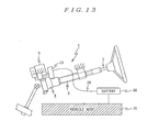
- This lead frame 23a is connected to a screw insertion hole 23b via a ground line (not shown) formed on the surface of the power module board 23, connected from this screw insertion hole 23b to the aluminum plate 22 via a screw 23c, and connected from this aluminum plate 22 to the flat surface 20 of the reduction gear box 4 via respective screws 22b to 22d. Thereafter, the lead frame 23a is connected to the conductive cover 26 via screws 26a to 26c. In this way, the reduction gear box 4, the conductive cover 26, and the control unit 19 are connected to a ground pin 28 of the power supply connector 24e. As shown in FIG. 13 , the power supply connector 24e is connected to the battery 30 serving as a power feeding unit via a battery ground harness 29 serving as a grounding line. A negative electrode side terminal of this battery 30 is grounded to a vehicle body side member 31.
- the thickness of the control unit 19 and a position of the flat attaching surface 20a of the control-unit mounting section 20 are set such that the control unit 19 is located further on the front side than a head of the bolt 18a for fixing the attachment flange 3c of the steering column 3 that serves as a stopper at the time of steering column contraction at the time of collapse in a rear end surface position of the cover 26 of the control unit 19 and a rearmost end position of the reduction gear box 4.
- the control unit 19 is mounted in a position where, at the time of collapse, which will be described later, the control unit 19 does not interfere with a moving member at the time of collapse.
- the power supply connector 24e and the signal connector 24f are disposed on a side of the control unit 19 opposite to the electric motor 5, i.e., on the right side of the vehicle.
- the electric motor 5, the control unit 19, the power supply connector 24e, and the signal connector 24f are linearly arranged. It is easy to connect the power supply connector 24e and the signal connector 24f to a battery side connector and a network side connector. Connections of the power supply connector 24d and the signal connector 24f to the connectors forming pairs with the connectors 24d and 24e, respectively, are each in a horizontal direction. It is possible to prevent penetration of drops of water and dust.
- the torque sensor 15 is fixedly arranged in the torque-sensor housing unit 16 of the reduction gear box 4 such that the distal ends of the external connection terminals 15c to 15f thereof extend to the rear of the vehicle body along the outer peripheral portion of the steering column 3.
- the control unit 19 is mounted on the control-unit mounting section 20 of the reduction gear box 4.
- heat radiation grease is applied to the flat attaching surface 20a and, then, the aluminum plate 22 is placed on the heat radiation grease and screwed to the flat attaching surface 20a by screws 22a to 22c.
- the power module board 23 is screwed to this aluminum plate 22 by a screw 23a.
- the synthetic resin frame 24 is placed on the flat attaching surface 20a to surround the power module board 23 and the attachment plate section 24b of the synthetic resin frame 24 is brought into contact with the frame attaching surface 20c of the reduction gear box 4 and screwed.
- the external connection terminals 15c to 15f of the torque sensor 15 are inserted through the through holes 25a to 25d of the control board 25 on a front side of the synthetic resin frame 24, i.e., the vehicle rear side, the through holes 25a to 25d and the external connection terminals 15c to 15f of the torque sensor 15 are soldered and the through hole 25h and the ground pin 28 are soldered, and, then, the conductive cover 26 and the partial cover 27 are attached, whereby the control unit 19 is configured.
- the steering shaft 2, the steering column 3, the worm 11, the worm wheel 13, and the like are mounted on the reduction gear box 4 and, finally, the electric motor 5 is attached to the motor mounting section 17 of the reduction gear box 4 and the bus bars 5c and 5d of the electric motor 5 are screwed to the terminal block 24c of the control unit 19.
- the battery ground harness 29, one end of which is separately connected to a positive electrode side terminal and a negative electrode side terminal of the battery 30, is connected to the power supply connector 24e.
- the first grounding path is formed in which the control board 25 is grounded via the ground pin 28 of the power supply connector 24e, the power module board 23 is grounded to the connection point 25i of this control board 25 via the lead frame 23a, the aluminum plate 22 is grounded to this power board plate 23 via the screw 23b, the reduction gear box 4 is grounded to this aluminum plate 22 via the screws 22a to 22c, and the conductive cover 26 and the partial cover 27 are grounded to the reduction gear box 4 via the screws 26a to 26c.
- This first grounding path is formed simply by assembling the control unit 19 to the reduction gear box 4. Moreover, the battery ground harness 29, one end of which is connected to the battery 30, is connected to the power supply connector 24e, whereby the grounding path is grounded to the negative electrode side terminal of the battery 30.
- the grounding path of the control unit 19, the reduction gear box 4, and the electric motor 5 can be formed by connecting the battery ground harness 29, which is connected to the battery 30, to the power supply connector 24e of the control unit 19 in this way. Unlike the example in the past described above, it is unnecessary to separately ground the reduction gear box 4 and the control unit 19 to the vehicle body side member. Therefore, it is possible to reduce the number of components and substantially improve assemblability.
- the reduction gear box 4 since the reduction gear box 4 is grounded, it is possible to improve electromagnetic compatibility (EMC) of the torque sensor 15 incorporated in the reduction gear box 4. Since the conductive cover 26 and the partial cover 27 of the control unit 19 are grounded, it is possible to surely prevent radio noise generated in the switching element such as the FET configuring the bridge circuit formed in the power module board 23 from being radiated to the outside and it is possible to surely prevent an electromagnetic wave from intruding into the control unit 19 from the outside, whereby it is possible to improve electromagnetic compatibility (EMC). Moreover, since the reduction gear box 4 and the control unit 19 are grounded to the battery 30 via the common battery ground harness 29, an earth potential difference does not occur between the reduction gear box 4 and the control unit 10. It is possible to surely control a fall in electromagnetic compatibility (EMC) and fluctuation in control accuracy caused by the earth potential difference.
- EMC electromagnetic compatibility
- the bus bars 5c and 5d of the electric motor 5 can be electrically connected directly to the terminal block 24c of the control unit 19 without the intervention of a motor harness.
- the external connection terminals 15c to 15f of the torque sensor 15 and the through holes 25a to 25d of the control board 25 can be electrically connected directly without the intervention of a signal cable. Therefore, the electric connection length between the control unit 19 and the electric motor 5 and torque sensor 15 can be minimized and a wiring resistance can be minimized. It is possible to control a power loss and surely prevent electric noise from being mixed in the electric connection.
- the attachment plate section 24b is formed near the terminal block 24c connected to the bus bars 5c and 5d of the electric motor 5 formed in the synthetic resin frame 24 in the control unit 19.
- This attachment plate section 24b is fixed to the frame attaching surface 20c formed in the motor mounting section 17 of the reduction gear box 4. Therefore, the terminal block 24c can generate, with vibration of the vehicle, vibration different from that of the reduction gear box 4 to prevent stress concentration from occurring in the terminal block 24c and improve rigidity of the terminal block 24c.
- the power module board 23 involving heat generation, which configures the control unit 19, is in contact with and connected to, via the aluminum plate 22, the flat attaching surface 20a in the control-unit mounting section 20 of the reduction gear box 4 formed of any one of aluminum, an aluminum alloy, magnesium, and a magnesium alloy. Therefore, it is possible to directly radiate the generated heat of the power module board 23 to the reduction gear box 4 serving as the heat mass with a large heat capacity via the aluminum plate 22 and the heat radiation grease and surely prevent the power module board 23 from coming into an overheated state. In this way, it is possible to further improve the effect of heat radiation to the reduction gear box 4 by applying the heat radiation grease between the aluminum plate 22 and the flat attaching surface 20a.
- the power module configured by the field effect transistor and the like involving heat generation is mounted on the power module board 23 and the control element such as the micro control unit 25g that rejects heat is mounted on the control board 25. Therefore, the generated heat of the power module board 23 is not directly transmitted to the control board 25. It is possible to surely prevent the generated heat of the power module board 23 from affecting the control board 25.
- the heat generating members such as the capacitor 25e mounted on the control board 25 are arranged in the upper part. Therefore, it is possible to surely prevent the heat generated by the heat generating members from affecting the control elements disposed in the lower part and on the opposite side of the heat generating members.
- the control unit 19 it is possible to reduce the length in the axial direction of the entire reduction gear box 4 and realize a reduction in size thereof by arranging the control unit 19 above the torque-sensor housing unit 16 of the reduction gear box 4.
- the upper attachment bracket 6 and the lower attachment bracket 7 are attached to the vehicle body side member and, then, the connection connector of the network such as the CAN is attached to the signal connector 24f of the control unit 19 from the vehicle body right side, whereby the assembly of the electric power steering apparatus 1 is completed.
- the connection of the external connection connectors to the power supply connector 24e and the signal connector 24f can be performed from the vehicle body right side. Therefore, it is possible to easily perform connection of both the connectors.
- the sliding plate section 6f is fixed to the capsule 6d configuring the attachment plate section 6a by the resin injection 6e.
- this control unit 19 is arranged in a position where the control unit 19 does not interfere with moving components in a state in which a predetermined collapse stroke is secured. Therefore, the control unit 19 does not interfere with the moving components to prevent collapse. It is possible to secure the necessary collapse stroke.
- this control unit 19 has a problem in that it is difficult to control the crush of the synthetic resin frame 24 and variation occurs in an energy absorption amount at the time of collapse.
- the crush of the control unit 19 is not taken into account to secure a collapse stroke, it is possible to secure a stable energy absorption amount as specified by a set value at the time of collapse.
- the grounding path between the control unit 19 and the reduction gear box 4 is a grounding path different from that in the first embodiment.
- the grounding path in the control unit 19 is a second grounding path different from the first grounding path in the first embodiment.
- the ground pin 28 of the power supply connector 24e is inserted through the through hole 25h of the control board 25 to ground the control board 25.
- a ground line 41 is formed from this through hole 25h to a connection terminal 40 provided on the surface of the control board 25.
- This connection terminal 40 is set in contact with conductive cover 26 to ground the conductive cover 26.
- the conductive cover 26 is mounted on the flat attaching surface 20a of the reduction gear box 4 via the screws 26a to 26c, whereby the reduction gear box 4 is grounded.
- the power module board 23 is grounded to the flat attaching surface 20a via the aluminum plate 22.
- the battery ground harness 29, one end of which is connected to the battery 30, is connected to the power supply connector 24e of the control unit 19. Consequently, it is possible to ground the reduction gear box 4, the electric motor 5, and the control unit 19 to the negative electrode side terminal of the battery 30. It is possible to easily form this second grounding path by assembling the control unit 19 to the reduction gear box 4.
- the present invention is not limited to this.
- the first grounding path in the first embodiment in which the control board 25, the power module board 23, the aluminum plate 22, the reduction gear box 4, the conductive cover 26, and the partial cover 27 are connected in this order and the second grounding path in the second embodiment in which the control board 25, the conductive cover 26, the reduction gear box, the aluminum plate 22, and the power module board 23 are connected in this order may be formed in parallel, as shown in FIG. 18 .
- the double grounding paths are formed, even if disconnection or a connection failure occurs in one of the grounding path, it is possible to surely hold the grounding in the other grounding path.
- the case in which the power module board 23 is attached to the flat attaching surface 20a of the reduction gear box 4 via the aluminum plate 22 is explained.
- the power module board 23 itself may be made of an aluminum board to omit the aluminum plate 22.
- the case in which the bus bars 5c and 5d of the electric motor 5 linearly extend is explained.
- the present invention is not limited to this. As shown in FIG. 19A , the bus bars 5c and 5d may be once bent in an axial direction of the electric motor 5 and, then, extended outward in a direction orthogonal to the axial direction.
- the bus bars 5c and 5d may be projected in the axial direction of the electric motor 5 first and, then, extended outward in the direction orthogonal to the axial direction.
- a contact surface between the bus bars 5c and 5d and the terminal block 24c of the control unit 19 is set to be within a plane including an attaching surface P1 of the attachment flange section 5b of the electric motor 5 in contact with the motor attaching surface 17 of the reduction gear box 4.
- bus bars 5c and 5d are provided in the electric motor 5 and the terminal block 24c is provided in the control unit 19 is explained.
- a terminal block may be provided in the electric motor 5 and bus bars may be provided in the control unit 19.
- the external connection terminals are not limited to bus bars. Arbitrary electric connection terminals can be applied.
- the case in which the external connection terminals 15c to 15f of the torque sensor 15 are bent in an L shape and inserted through the through holes 25a to 25d of the control board 25 is explained.
- the present invention is not limited to this.
- a guide member having a funnel-like guide surface may be provided on a side for inserting the external connection terminals 15c to 15f of the through holes 25a to 25d.
- the case in which the external connection terminals 15c to 15f of the torque sensor 15 are formed in an L shape is explained.
- the external connection terminals 15c to 15f may be formed in a linear shape and electrically connected by soldering, fusing, or the like along a connection land formed on the control board 25.
- the external connection terminals may be formed as clip terminals and clip the control board 25.
- the case in which the flat attaching surface 20a of the control-unit mounting section 20 of the reduction gear box 4 is the plane orthogonal to the center axis of the steering column 3 is explained.
- the flat attaching surface 20a may be a surface inclined with respect to a surface orthogonal to the center axis of the steering column 3.
- the case in which the electric motor 5, the control unit 19, and the connectors 24e and 24f are linearly arranged along the line orthogonal to the center axis of the steering column 3 is explained.
- the electric motor 5, the control unit 19, and the connectors 24e and 24f may be linearly arranged along a line crossing the center axis of the steering column 3.
- the case in which the power supply connector 24e and the signal connector 24f of the control unit 19 have the connection openings thereof on the right end side is explained.
- the present invention is not limited to this. With the connection openings set in a direction along the axial direction of the steering column 3, the external connectors may be attached from the axial direction of the steering column 3.
- the present invention is not limited to this.
- the synthetic resin frame 24 may be fixed to the flat attaching surface 20a after the power module board 23 and the control board 25 are attached to the synthetic resin frame 24.
- a part of the synthetic resin frame 24 and the power module board 23 may be fastened together.
- the present invention is not limited to this.
- the synthetic resin frame 24 may be fixed to the flat attaching surface 20a after the power module board 23 and the control board 25 are attached to the synthetic resin frame 24.
- a part of the synthetic resin frame 24 and the power module board 23 may be fastened together.
- the brush motor is applied as the electric motor 5 .
- the present invention is not limited to this.
- a brushless motor may be applied.
- FET field effect transistor
- the present invention is not limited to this.
- the electric motor 5, and the control unit 19 it is sufficient to arrange the electric motor 4 surface-symmetrically to the control unit 19 across a vertical surface passing the center axis of the steering column 3, i.e., on the right side of the control unit 19 and arrange the power supply connector 24e and the signal connector 24f of the control unit 19 on the left side.
- the electric motor 4 may be arranged on the vehicle outer side and the power supply connector 24e and the signal connector 24f may be arranged on the vehicle inner side.
- a control unit including a board mounted with a control circuit that controls to drive an electric motor is mounted on a reduction gear box, a connecting section of the electric motor is electrically connected to the control unit directly, and connection of the reduction gear box and the control unit to the ground is performed via a grounding line disposed between the control unit and a power feeding unit. Therefore, it is possible to obtain an electric power steering apparatus in which the reduction gear box and the control unit can be grounded to the power feeding unit via a common ground line, electromagnetic compatibility (EMC) of the reduction gear box can be improved, and the number of components and man-hour can be reduced to improve assemblability.
- EMC electromagnetic compatibility
Landscapes
- Engineering & Computer Science (AREA)
- Power Engineering (AREA)
- Chemical & Material Sciences (AREA)
- Combustion & Propulsion (AREA)
- Transportation (AREA)
- Mechanical Engineering (AREA)
- Microelectronics & Electronic Packaging (AREA)
- Power Steering Mechanism (AREA)
Abstract
Description
- The present invention relates to an electric power steering apparatus including a steering column having inserted therein a steering shaft to which steering torque is transmitted and an electric motor that transmits a steering assisting force to the steering column via a reduction mechanism in a reduction gear box.
- As an electric power steering apparatus in the past, for example, as described in
JP2005-329866A JP2005-329867A JP2005-329868A JP2005-329869A - However, in the example in the past disclosed in
JP2005-329866A JP2005-329867A JP2005-329868A JP2005-329869A - Moreover, in a column-type electric power steering apparatus as the electric power steering apparatus, for example, as described in
JP2004-131047A - In this way, in the column-type electric power steering apparatus, ground wires are necessary in both the column housing and the control circuit. Therefore, there is an unsolved problem in that assemblability of the electric power steering apparatus falls, a relative potential difference occurs because the ground wires in two routes are wired to different places of a vehicle, respectively, and a fall in electromagnetic compatibility (EMC) and fluctuation in control accuracy due to the occurrence of the earth potential difference occur.
Therefore, the present invention has been devised in view of the unsolved problems of the examples in the past and it is an object of the present invention to provide an electric power steering apparatus in which ground processing for respective sections requiring a ground can be reduced to necessary minimum to improve assemblability and a fall in electromagnetic compatibility and fluctuation in control accuracy can be controlled. - In order to attain the object described above, an electric power steering apparatus according to
claim 1 is an electric power steering apparatus including a steering column having inserted therein a steering shaft to which steering torque is transmitted and an electric motor that transmits a steering assisting force to the steering shaft via a reduction mechanism in a conductive reduction gear box. The electric power steering apparatus is characterized in that a control unit including a control board mounted with a control circuit that controls to drive the electric motor is mounted on the reduction gear box, a connecting section of the electric motor is electrically connected to the control unit directly, and connection of the reduction gear box and the control unit to a ground is performed via a grounding line disposed between the control unit and a power feeding unit. - An electric power steering apparatus according to
claim 2 is characterized in that, in the invention according toclaim 1, the control unit includes at least a power module board mounted with a power module involving heat generation that controls to drive the electric motor and an insulated frame that surrounds the power module board and includes a unit side connecting section that connects the connecting section of the electric motor and a power supply connector to which the grounding line is connected, the power module board is mounted on a control-unit mounting surface of the reduction gear box, and the grounding line is connected to the reduction gear box via the power module board. - Moreover, an electric power steering apparatus according to
claim 3 is characterized in that, in the invention according toclaim 1, the control unit includes at least a board mounted with the control circuit, an insulated frame that surrounds the board and includes a unit side connecting section that connects the connecting section of the electric motor and a power supply connector to which the grounding line is connected, and a conductive cover that covers the control board, the power module board, and the insulated frame, and the grounding line is connected to the reduction gear box via the conductive cover. - Furthermore, an electric power steering apparatus according to
claim 4 is characterized in that, in the invention according toclaim 3, the board includes a control board mounted with a command-value calculating unit that calculates a driving command value for the electric motor and a power module board mounted with a power module involving heat generation that controls to drive the electric motor on the basis of the driving command value from the command-value calculating unit.
Moreover, an electric power steering apparatus according toclaim 5 is characterized in that, in the invention according toclaim 1, the control unit includes at least a control board mounted with a command-value calculating unit that calculates a driving command value for the electric motor, a power module board mounted with a power module involving heat generation that controls to drive the electric motor, and an insulated frame that surrounds the control board and the power module board and includes a unit side connecting section that connects the connecting section of the electric motor and a power supply connector to which the grounding line is connected, the power module board is mounted on a control-unit mounting surface of the reduction gear box, and a first grounding path connected to the reduction gear box via the power module board and a second grounding path connected to the reduction gear box via the conductive cover are formed in parallel between the grounding line and the reduction gear box. - An electric power steering apparatus according to
claim 6 is characterized in that, in the invention according to any one ofclaims 1 to 5, the reduction gear box is made of a highly thermally conductive material.
Moreover, an electric power steering apparatus according toclaim 7 is characterized in that, in the invention according toclaim 6, the reduction gear box is formed by die-casting any one of aluminum, an aluminum alloy, magnesium, and a magnesium alloy. - Moreover, an electric power steering apparatus according to
claim 8 is characterized in that, in the invention according to any one ofclaims 1 to 7, the reduction gear box includes at least a worm housing unit that houses a worm coupled to an output shaft of the electric motor, a worm-wheel housing unit that houses a worm wheel coupled to the steering shaft, and a torque-sensor housing unit that is continuously connected to the worm-wheel housing unit, houses the torque sensor, and is coupled to a steering column, and a control-unit mounting section on which the control unit is mounted is formed in an outer periphery of the worm housing unit, the worm-wheel housing unit, and the torque-sensor housing unit. - Furthermore, an electric power steering apparatus according to claim 9 is characterized in that, in the invention according to
claim 8, a distal end of the torque-sensor housing unit is formed as a contraction stopper for the steering column at the time of collapse, and a contraction stopper side end surface position of the control unit mounted on the control-unit mounting section is set further on a worm-wheel housing unit side than the contraction stopper.
According to the present invention, the control unit including the board mounted with the control circuit that controls to drive the electric motor is mounted on the reduction gear box, the connecting section of the electric motor is electrically connected to the control unit directly, and the connection of the reduction gear box and the control unit to the ground is performed via the grounding line disposed between the control unit and the power feeding unit. Therefore, since the reduction gear box and the control unit are grounded to the power feeding unit via the common ground line, there is an effect that it is possible to improve electromagnetic compatibility (EMC) of the reduction gear box and it is possible to reduce the number of components and man-hour and improve assemblability of the electric power steering apparatus. - Since the grounding paths between the control unit and the reduction gear box are formed via the conductive cover, it is possible to improve electromagnetic compatibility of the control unit itself.
-
-
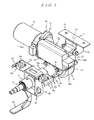
FIG. 1 is a perspective view showing an embodiment of an electric power steering apparatus according to the present invention; -
FIG. 2 is a front view of the electric power steering apparatus according to the present invention; -
FIG. 3 is a left side view ofFIG. 2 ; -
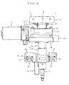
FIG. 4 is a plan view ofFIG. 2 ; -
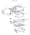
FIG. 5 is a disassembled perspective view of a main part of the present invention; -
FIG. 6 is a disassembled perspective view of the main part of the present invention viewed from a direction opposite to that inFIG. 5 ; -
FIG. 7 is a longitudinal sectional view showing a main part in a reduction gear box position in enlargement; -
FIG. 8 is a front view showing the structure of bus bars of an electric motor; -
FIG. 9 is a perspective view showing a relation between the reduction gear box and a control board; -
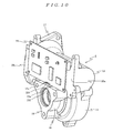
FIG. 10 is a perspective view showing a state in which external connection terminals of a torque sensor in the reduction gear box are inserted through the control board; -
FIGS. 11A and 11B are the perspective view showing, in enlargement, a main part in which a connection relation between the electric motor and a control unit is shown; -
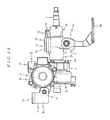
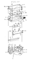
FIG. 12 is a disassembled perspective view showing a first grounding path; -
FIG. 13 is an overall diagram showing grounding to a battery; -
FIG. 14 is a perspective view showing the electric power steering apparatus at the time of collapse; -
FIG. 15 is a left side view of the electric power steering apparatus at the time of collapse; -
FIG. 16 is a plan view of the electric power steering apparatus at the time of collapse; -
FIG. 17 is a disassembled perspective view showing a second grounding path in a second embodiment of the present invention; -
FIG. 18 is a disassembled perspective view showing first and second grounding paths in another embodiment of the present invention; and -
FIGS. 19A, 19B and 19C are the perspective view showing a modification of the bus bars of the electric motor. - Embodiments of the present invention will be hereinafter explained on the basis of the drawings.
FIG. 1 is a perspective view showing an example of a case in which a first embodiment of the present invention is applied to a right-hand drive car.FIG. 2 is a front view,FIG. 3 is a left side view,FIG. 4 is a plan view, andFIGS. 5 and6 are disassembled perspective views of a main part of the example.
InFIG. 1 ,reference numeral 1 denotes a column-type electric power steering apparatus. Areduction gear box 4 is coupled to asteering column 3 in which asteering shaft 2 coupled to a steering wheel (not shown) is inserted rotatably. In thisreduction gear box 4, anelectric motor 5 including a brush motor, an axial direction of which is extended in a direction orthogonal to an axial direction of thesteering column 3, is disposed. - The
steering column 3 has, in a coupling section with thereduction gear box 4, a double tube structure including aninner tube 3a and anouter tube 3b for absorbing impact energy at the time of collapse and securing a predetermined collapse stroke. Theouter tube 3b of thesteering column 3 and thereduction gear box 4 are attached to a vehicle body side by anupper attachment bracket 6 and alower attachment bracket 7.
Thelower attachment bracket 7 is formed by anattachment plate section 7a attached to a vehicle body side member (not shown) and a pair of supportingplate sections 7b that extend in parallel while keeping a predetermined space with respect to a lower surface of thisattachment plate section 7a. A distal end of the supportingplate section 7b is pivotally coupled to, via apivot 7c, a supportingsection 4b integrally formed in acover 4a disposed on a lower end side of thereduction gear box 4, i.e., a vehicle front side. - The
upper attachment bracket 6 includes anattachment plate section 6a attached to the vehicle body side member (not shown), a square frame-shaped supportingsection 6b formed integrally with thisattachment plate section 6a, and atilt mechanism 6c, which supports theouter tube 3b of thesteering column 3, formed in this square frame-shaped supportingsection 6b. Theattachment plate section 6a includes a pair of left andright capsules 6d attached to the vehicle body side member (not shown) and asliding plate section 6f fixed to thesecapsules 6d by aresin injection 6e. When a load for moving thesteering column 3 to the vehicle front is applied thereto at the time of collision, thesliding plate section 6f slides to the vehicle front with respect to thecapsule 6d, theresin injection 6e is sheared, and a load of the shearing acts as a collapse start load. It is possible to adjust a tilt position of thesteering column 3 up and down around thepivot 7c of thelower attachment bracket 7 by releasing a supporting state by pivoting atilt lever 6g of thetilt mechanism 6c. - As shown in
FIG. 7 , thesteering shaft 2 includes aninput shaft 2a, an upper end of which is coupled to the steering wheel (not shown), and anoutput shaft 2c that is coupled to a lower end of thisinput shaft 2a via atorsion bar 2b and covers thetorsion bar 2b.
Moreover, as shown inFIGS. 5 to 7 , thereduction gear box 4 is formed by, for example, die-casting a material having high heat conductivity and electric conductivity, for example, any one of aluminum, an aluminum alloy, magnesium, and a magnesium alloy. - This
reduction gear box 4 includes aworm housing unit 12 that houses aworm 11 coupled to theoutput shaft 5a of theelectric motor 5, a worm-wheel housing unit 14 that is provided on a lower side of thisworm housing unit 12, has a center axis orthogonal to a center axis of theworm housing unit 12, and houses aworm wheel 13 that meshes with theworm 11, a torque-sensor housing unit 16 that is integrally and coaxially coupled to a rear side of this worm-wheel housing unit 14 and houses atorque sensor 15, amotor mounting section 17 that is formed in an open end face of theworm housing unit 12 and to which theelectric motor 5 is attached, acolumn attaching section 18 that is formed in an rear end face of the torque-sensor housing unit 16 and to which anattachment flange 2a formed at a front end of thesteering column 3 is attached, and a control-unit mounting section 20 that is formed in a plane orthogonal to a center axis of the worm-wheel housing unit 14 and the torque-sensor housing unit 16 across a part of theworm housing unit 12 and the worm-wheel housing unit 14 and on which acontrol unit 19 is mounted. Thereduction gear box 4 is fixed to thesteering column 3 by abolt 18a in a state in which theattachment flange 3c of thesteering column 3 is brought into contact with thecolumn attaching section 18. - As shown in
FIG. 7 , thetorque sensor 15 is configured to magnetically detect a twist state between theinput shaft 2a and theoutput shaft 2c of thesteering shaft 2 and detect steering torque transmitted to the steering shaft with a pair ofdetection coils External connection terminals steering column 3, are connected to starts and ends of winding of these pair ofdetection coils external connection terminals 15c to 15f are bent, in the center thereof, in parallel to the center axis of thesteering column 3 and formed in an L shape. - In the
electric motor 5, in a position close to and opposed to thecontrol unit 19 mounted on the control-unit mounting section 20 in a position closer to anattachment flange section 5b of theelectric motor 5, bus bars 5c and 5d serving as connection terminals connected to a built-in brush are protrudingly formed toward the rear of the vehicle body perpendicular to an axis direction of theelectric motor 5 and to be substantially parallel to the center axis of thesteering column 3.Long holes 5e through which fixing screws are inserted are drilled at distal end portions of thesebus bars
As shown inFIG. 8 , therespective bus bars brush supporting member 5f made of synthetic resin having an armature insertion hole in the center of a bottom portion thereof. The bus bars 5c and 5d includearcuate conductor sections brushes terminal sections arcuate conductor sections electric motor 5 is attached with theattachment flange section 5b thereof coupled to themotor mounting section 17 of thereduction gear box 4, theworm 11 coupled to theoutput shaft 5a thereof, and the bus bars 5c and 5d extended to the rear of the vehicle body. - Moreover, as it is evident with reference to
FIG. 9 , in the control-unit mounting section 20 formed in thereduction gear box 4, a flat attachingsurface 20a is formed by theworm housing unit 12 and an upper side of the worm-wheel housing unit 14 on a lower side of theworm housing unit 12. The control-unit mounting section 20 is formed in an L shape viewed from a left side surface by the flat attachingsurface 20a and aflat surface 20b formed on an upper surface of the torque-sensor housing unit 16 and orthogonal to the flat attachingsurface 20a. A narrowframe attaching surface 20c is also formed on a rear end surface of themotor mounting section 17 in parallel to the flat attachingsurface 20a and in a position further on a rear side than the flat attachingsurface 20a. Theexternal connection terminals 15c to 15f of thetorque sensor 15 are projected from the center in the left to right direction of theflat surface 20b in the torque-sensor housing unit 16. - As shown in
FIGS. 5 ,6 , and10 , thecontrol unit 19 mounted on this control-unit mounting section 20 includes analuminum plate 22 directly fixed to theflat surface 20, apower module board 23 fixed to thisaluminum plate 22, asynthetic resin frame 24 as an insulated frame that surrounds thealuminum plate 22 and thepower module board 23, acontrol board 25 attached to the front of thissynthetic resin frame 24, and aconductive cover 26 that covers these members. - The
aluminum plate 22 has a size fit in thesynthetic resin frame 24 and is placed on and screwed to theflat surface 20 via heat radiation grease.
Thepower module board 23 is mounted with, on a surface thereof, an H bridge circuit including a power switching element such as a field effect transistor, which controls to drive theelectric motor 5, and a power module such as a pulse width modulation circuit, which drives the power switching element of this H bridge circuit, and is closely attached and screwed to thealuminum plate 22 on a rear surface thereof. - The
synthetic resin frame 24 has integrally formed therein a framemain body 24a of a rectangular frame shape, anattachment plate section 24b that is protrudingly formed in a position opposed to the bus bars 5c and 5d of theelectric motor 5 at a left end of this framemain body 24a and is fixed to theframe attaching surface 20c of thereduction gear box 4, aterminal block 24c that is projected in an L shape from thisattachment plate section 24b and electrically connects the bus bars 5c and 5d of theelectric motor 5 as shown inFIGS. 11A and 11B , apower supply connector 24e that is disposed in a center position at a right end of the framemain body 24a and connected to abattery 30 described later, and asignal connector 24f that performs exchange of data with control devices of respective units of the vehicle body and is connected to a network such as a CAN. In the respectivepower supply connector 24e andsignal connector 24f, connection connector insertion openings are formed on right end sides such that external connection connectors connected to these connectors are inserted from a right side of the vehicle body. - In the
control board 25, throughholes 25a to 25d, through which theexternal connection terminals 15c to 15f of thetorque sensor 15 attached to the front of thesynthetic resin frame 24 are directly inserted, are drilled. Thecontrol board 25 is mounted with a micro control unit (MCU) that calculates a steering assisting current command value on the basis of a torque detection value from thetorque sensor 15 and a vehicle speed detection value from a not-shown speed sensor and performs current feedback control on the basis of this steering assisting current command value and a detection value of a motor current outputted to theelectric motor 5 to calculate a voltage command value to the pulse width modulation circuit of thepower module board 23 to thereby control a steering assisting force generated by theelectric motor 5 and peripheral devices of the MCU. - Specifically, as shown in
FIGS. 5 and6 , in thecontrol board 25, large components such as acapacitor 25e and apower relay 25f are arranged to be aligned in the left to right direction on an upper side on a front side opposed to thepower module board 23. A micro control unit (MCU) 25g and peripheral devices of the MCU 25g are disposed on a lower side on a rear side thereof. As shown inFIG. 7 , an arrangement position of the large components such as thecapacitor 25e and thepower relay 25f is a position where the large components such as thecapacitor 25e and thepower relay 25f are above an upper edge of the control-unit mounting section 20 formed in thereduction gear box 4 when thecontrol board 25 is attached to thesynthetic resin frame 24. Distal ends of these large components are set to be in a state in which the distal ends project to above theworm housing 12 through acutout section 22a formed in an upper part of thealuminum plate 22. Projecting portions of these large components are covered with apartial cover 27. In this way, the large components such as thecapacitor 25e and thepower relay 25f are arranged above thecontrol board 25 and to be projected to the side above theworm housing unit 12. Consequently, it is possible to effectively use a free space on an upper side of theworm housing unit 12 in thereduction gear box 4, reduce the thickness from thepower module board 23 of thecontrol unit 19 to a rear end face of theconductive cover 26, and reduce a size of thecontrol unit 19. - The
control unit 19 having the structure described above is assembled as described below. First, heat radiation grease is applied to a mounting position of thepower module board 23 on the flat attachingsurface 20a in the control-unit mounting section 20 of thereduction gear box 4 and, then, thepower module board 23 is placed on the heat radiation grease and screwed to the flat attachingsurface 20a. Subsequently, thesynthetic resin frame 24 is placed on the flat attachingsurface 20a and theframe attaching surface 20c to surround thepower module board 23. Theattachment plate section 24b of thesynthetic resin frame 24 is screwed to theframe attaching surface 20c of thereduction gear box 4 in the same manner. After or before screwing theattachment plate section 24b, thecontrol board 25 is screwed on a front side of thesynthetic resin frame 24 after theexternal connection terminals 15c to 15f of thetorque sensor 15 are inserted through the throughholes 25a to 25d of thecontrol board 25. Subsequently, theexternal connection terminals 15c to 15f and the throughholes 25a to 25d are soldered and, then, finally, theconductive cover 26 is attached to the flat attachingsurface 25a and thepartial cover 27 is attached to theconductive cover 26 to cover the large components from the front surface side. - When the assembly of the
control unit 19 is completed in this way, as shown inFIG. 12 , an L-shapedground pin 28 projected into thesynthetic resin frame 24 from thepower supply connector 24e and bent upward is inserted through a throughhole 25h of thecontrol board 25. This throughhole 25h is connected to acontact point 25i via a ground line (not shown) formed on a rear surface side of thecontrol board 25. Alead frame 23a formed on the surface of thepower module board 23 is connected to this connection point. Thislead frame 23a is connected to ascrew insertion hole 23b via a ground line (not shown) formed on the surface of thepower module board 23, connected from thisscrew insertion hole 23b to thealuminum plate 22 via ascrew 23c, and connected from thisaluminum plate 22 to theflat surface 20 of thereduction gear box 4 viarespective screws 22b to 22d. Thereafter, thelead frame 23a is connected to theconductive cover 26 viascrews 26a to 26c. In this way, thereduction gear box 4, theconductive cover 26, and thecontrol unit 19 are connected to aground pin 28 of thepower supply connector 24e. As shown inFIG. 13 , thepower supply connector 24e is connected to thebattery 30 serving as a power feeding unit via abattery ground harness 29 serving as a grounding line. A negative electrode side terminal of thisbattery 30 is grounded to a vehiclebody side member 31. - Thereafter, the
steering column 3, the steeringshaft 2, theworm 11, and theworm wheel 13 are assembled and, finally, theelectric motor 5 is assembled. As shown inFIGS. 11A and 11B , the bus bars 5c and 5d are screwed to theterminal block 24c of thecontrol unit 19.
In this way, in a state in which thecontrol unit 19 is mounted on the control-unit mounting section 20 of thereduction gear box 4, the thickness of thecontrol unit 19 and a position of the flat attachingsurface 20a of the control-unit mounting section 20 are set such that thecontrol unit 19 is located further on the front side than a head of thebolt 18a for fixing theattachment flange 3c of thesteering column 3 that serves as a stopper at the time of steering column contraction at the time of collapse in a rear end surface position of thecover 26 of thecontrol unit 19 and a rearmost end position of thereduction gear box 4. Thecontrol unit 19 is mounted in a position where, at the time of collapse, which will be described later, thecontrol unit 19 does not interfere with a moving member at the time of collapse. - Since it is unnecessary to provide a motor harness between the electric motor and the control unit, noise radiated from the motor harness is reduced and it is possible to reduce the influence on radio noise.
Thepower supply connector 24e and thesignal connector 24f are disposed on a side of thecontrol unit 19 opposite to theelectric motor 5, i.e., on the right side of the vehicle. Theelectric motor 5, thecontrol unit 19, thepower supply connector 24e, and thesignal connector 24f are linearly arranged. It is easy to connect thepower supply connector 24e and thesignal connector 24f to a battery side connector and a network side connector. Connections of thepower supply connector 24d and thesignal connector 24f to the connectors forming pairs with theconnectors - Next, operations in the first embodiment are explained.
First, to assemble an electricpower steering apparatus 1, thetorque sensor 15 is fixedly arranged in the torque-sensor housing unit 16 of thereduction gear box 4 such that the distal ends of theexternal connection terminals 15c to 15f thereof extend to the rear of the vehicle body along the outer peripheral portion of thesteering column 3.
Subsequently, thecontrol unit 19 is mounted on the control-unit mounting section 20 of thereduction gear box 4. In this mounting of thecontrol unit 19, first, heat radiation grease is applied to the flat attachingsurface 20a and, then, thealuminum plate 22 is placed on the heat radiation grease and screwed to the flat attachingsurface 20a byscrews 22a to 22c. Thepower module board 23 is screwed to thisaluminum plate 22 by ascrew 23a. - In this state, the
synthetic resin frame 24 is placed on the flat attachingsurface 20a to surround thepower module board 23 and theattachment plate section 24b of thesynthetic resin frame 24 is brought into contact with theframe attaching surface 20c of thereduction gear box 4 and screwed. Moreover, theexternal connection terminals 15c to 15f of thetorque sensor 15 are inserted through the throughholes 25a to 25d of thecontrol board 25 on a front side of thesynthetic resin frame 24, i.e., the vehicle rear side, the throughholes 25a to 25d and theexternal connection terminals 15c to 15f of thetorque sensor 15 are soldered and the throughhole 25h and theground pin 28 are soldered, and, then, theconductive cover 26 and thepartial cover 27 are attached, whereby thecontrol unit 19 is configured. - Subsequently, the steering
shaft 2, thesteering column 3, theworm 11, theworm wheel 13, and the like are mounted on thereduction gear box 4 and, finally, theelectric motor 5 is attached to themotor mounting section 17 of thereduction gear box 4 and the bus bars 5c and 5d of theelectric motor 5 are screwed to theterminal block 24c of thecontrol unit 19. Thebattery ground harness 29, one end of which is separately connected to a positive electrode side terminal and a negative electrode side terminal of thebattery 30, is connected to thepower supply connector 24e.
Consequently, as described above, the first grounding path is formed in which thecontrol board 25 is grounded via theground pin 28 of thepower supply connector 24e, thepower module board 23 is grounded to theconnection point 25i of thiscontrol board 25 via thelead frame 23a, thealuminum plate 22 is grounded to thispower board plate 23 via thescrew 23b, thereduction gear box 4 is grounded to thisaluminum plate 22 via thescrews 22a to 22c, and theconductive cover 26 and thepartial cover 27 are grounded to thereduction gear box 4 via thescrews 26a to 26c. - This first grounding path is formed simply by assembling the
control unit 19 to thereduction gear box 4. Moreover, thebattery ground harness 29, one end of which is connected to thebattery 30, is connected to thepower supply connector 24e, whereby the grounding path is grounded to the negative electrode side terminal of thebattery 30.
The grounding path of thecontrol unit 19, thereduction gear box 4, and theelectric motor 5 can be formed by connecting thebattery ground harness 29, which is connected to thebattery 30, to thepower supply connector 24e of thecontrol unit 19 in this way. Unlike the example in the past described above, it is unnecessary to separately ground thereduction gear box 4 and thecontrol unit 19 to the vehicle body side member. Therefore, it is possible to reduce the number of components and substantially improve assemblability. - Moreover, since the
reduction gear box 4 is grounded, it is possible to improve electromagnetic compatibility (EMC) of thetorque sensor 15 incorporated in thereduction gear box 4. Since theconductive cover 26 and thepartial cover 27 of thecontrol unit 19 are grounded, it is possible to surely prevent radio noise generated in the switching element such as the FET configuring the bridge circuit formed in thepower module board 23 from being radiated to the outside and it is possible to surely prevent an electromagnetic wave from intruding into thecontrol unit 19 from the outside, whereby it is possible to improve electromagnetic compatibility (EMC). Moreover, since thereduction gear box 4 and thecontrol unit 19 are grounded to thebattery 30 via the commonbattery ground harness 29, an earth potential difference does not occur between thereduction gear box 4 and thecontrol unit 10. It is possible to surely control a fall in electromagnetic compatibility (EMC) and fluctuation in control accuracy caused by the earth potential difference. - By configuring the
control unit 19 as described above, the bus bars 5c and 5d of theelectric motor 5 can be electrically connected directly to theterminal block 24c of thecontrol unit 19 without the intervention of a motor harness. Theexternal connection terminals 15c to 15f of thetorque sensor 15 and the throughholes 25a to 25d of thecontrol board 25 can be electrically connected directly without the intervention of a signal cable. Therefore, the electric connection length between thecontrol unit 19 and theelectric motor 5 andtorque sensor 15 can be minimized and a wiring resistance can be minimized. It is possible to control a power loss and surely prevent electric noise from being mixed in the electric connection. - Moreover, the
attachment plate section 24b is formed near theterminal block 24c connected to the bus bars 5c and 5d of theelectric motor 5 formed in thesynthetic resin frame 24 in thecontrol unit 19. Thisattachment plate section 24b is fixed to theframe attaching surface 20c formed in themotor mounting section 17 of thereduction gear box 4. Therefore, theterminal block 24c can generate, with vibration of the vehicle, vibration different from that of thereduction gear box 4 to prevent stress concentration from occurring in theterminal block 24c and improve rigidity of theterminal block 24c. - The
power module board 23 involving heat generation, which configures thecontrol unit 19, is in contact with and connected to, via thealuminum plate 22, the flat attachingsurface 20a in the control-unit mounting section 20 of thereduction gear box 4 formed of any one of aluminum, an aluminum alloy, magnesium, and a magnesium alloy. Therefore, it is possible to directly radiate the generated heat of thepower module board 23 to thereduction gear box 4 serving as the heat mass with a large heat capacity via thealuminum plate 22 and the heat radiation grease and surely prevent thepower module board 23 from coming into an overheated state. In this way, it is possible to further improve the effect of heat radiation to thereduction gear box 4 by applying the heat radiation grease between thealuminum plate 22 and the flat attachingsurface 20a. - Moreover, the power module configured by the field effect transistor and the like involving heat generation is mounted on the
power module board 23 and the control element such as the micro control unit 25g that rejects heat is mounted on thecontrol board 25. Therefore, the generated heat of thepower module board 23 is not directly transmitted to thecontrol board 25. It is possible to surely prevent the generated heat of thepower module board 23 from affecting thecontrol board 25. Moreover, the heat generating members such as thecapacitor 25e mounted on thecontrol board 25 are arranged in the upper part. Therefore, it is possible to surely prevent the heat generated by the heat generating members from affecting the control elements disposed in the lower part and on the opposite side of the heat generating members. - Moreover, it is possible to reduce the length in the axial direction of the entire
reduction gear box 4 and realize a reduction in size thereof by arranging thecontrol unit 19 above the torque-sensor housing unit 16 of thereduction gear box 4.
Theupper attachment bracket 6 and thelower attachment bracket 7 are attached to the vehicle body side member and, then, the connection connector of the network such as the CAN is attached to thesignal connector 24f of thecontrol unit 19 from the vehicle body right side, whereby the assembly of the electricpower steering apparatus 1 is completed. In this way, the connection of the external connection connectors to thepower supply connector 24e and thesignal connector 24f can be performed from the vehicle body right side. Therefore, it is possible to easily perform connection of both the connectors. In this case, in theupper attachment bracket 6, as shown inFIG. 1 , the slidingplate section 6f is fixed to thecapsule 6d configuring theattachment plate section 6a by theresin injection 6e. - When this assembly of the electric
power steering apparatus 1 is completed, it is possible to release a tilt lock state by pivoting thetilt lever 6g of theupper attachment bracket 6 and adjust a tilt position by pivoting thesteering column 3 in this state around thepivot 7c of thelower attachment bracket 7.
When a not-shown ignition switch of the vehicle is turned on to supply electric power to thepower module board 23 and thecontrol board 25 from thebattery 30, steering assistance control processing is executed by the micro control unit (MCU) and a steering assisting current command value is calculated on the basis of detection values of thetorque sensor 15 and the not-shown speed sensor. Current feedback processing is executed on the basis of this steering assisting current command value and a motor current detected by a motor-current detecting unit to calculate a voltage command value. This voltage command value is supplied to a gate driving circuit of thepower module board 23 to control the H bridge circuit, whereby a motor driving current flows to theelectric motor 5 to drive theelectric motor 5 to generate a necessary steering assisting force in a normal or reverse rotating direction. - Therefore, a steering assisting force corresponding to steering torque of the steering wheel is generated from the
electric motor 5 and this steering assisting force is transmitted to an output of the steering shaft via theworm 11 and theworm wheel 13. Consequently, it is possible to steer the steering wheel with a light steering force.
In this state, when a driver touches the not-shown steering wheel at the time of occurrence of collapse and a load that slides thesteering column 3 forward acts on thesteering column 3, as shown inFIGS. 14 to 16 , theresin injection 6e between thecapsule 6d and the slidingplate section 6f of theupper attachment bracket 6 is sheared. Consequently, theouter tube 3b slides with respect to theinner tube 3a on theattachment flange 3c side of thesteering column 3 while absorbing the load and comes into contact with the head of thebolt 18a serving as the contraction stopper, whereby thesteering column 3 contracts while securing a necessary collapse stroke. - When the
steering column 3 contracts in this way, the members attached around thesteering column 3 approach thecontrol unit 19. However, thiscontrol unit 19 is arranged in a position where thecontrol unit 19 does not interfere with moving components in a state in which a predetermined collapse stroke is secured. Therefore, thecontrol unit 19 does not interfere with the moving components to prevent collapse. It is possible to secure the necessary collapse stroke.
Incidentally, although it is conceivable to crush thecontrol unit 19 as well in order to secure a collapse stroke at the time of occurrence of collapse, as described above, thiscontrol unit 19 has a problem in that it is difficult to control the crush of thesynthetic resin frame 24 and variation occurs in an energy absorption amount at the time of collapse. However, in this embodiment, since the crush of thecontrol unit 19 is not taken into account to secure a collapse stroke, it is possible to secure a stable energy absorption amount as specified by a set value at the time of collapse. - Next, a second embodiment of the present invention is explained with reference to
FIG. 17 .
In this second embodiment, the grounding path between thecontrol unit 19 and thereduction gear box 4 is a grounding path different from that in the first embodiment.
In other words, in the second embodiment, as shown inFIG. 17 , the grounding path in thecontrol unit 19 is a second grounding path different from the first grounding path in the first embodiment. - In this second grounding path, as shown in
FIG. 17 , theground pin 28 of thepower supply connector 24e is inserted through the throughhole 25h of thecontrol board 25 to ground thecontrol board 25. Aground line 41 is formed from this throughhole 25h to aconnection terminal 40 provided on the surface of thecontrol board 25. Thisconnection terminal 40 is set in contact withconductive cover 26 to ground theconductive cover 26. Theconductive cover 26 is mounted on the flat attachingsurface 20a of thereduction gear box 4 via thescrews 26a to 26c, whereby thereduction gear box 4 is grounded. Moreover, thepower module board 23 is grounded to the flat attachingsurface 20a via thealuminum plate 22. - In this second embodiment, as in the first embodiment, the
battery ground harness 29, one end of which is connected to thebattery 30, is connected to thepower supply connector 24e of thecontrol unit 19. Consequently, it is possible to ground thereduction gear box 4, theelectric motor 5, and thecontrol unit 19 to the negative electrode side terminal of thebattery 30. It is possible to easily form this second grounding path by assembling thecontrol unit 19 to thereduction gear box 4.
In the first embodiment and the second embodiment, the case in which the first grounding path and the second grounding path are separately provided. However, the present invention is not limited to this. The first grounding path in the first embodiment in which thecontrol board 25, thepower module board 23, thealuminum plate 22, thereduction gear box 4, theconductive cover 26, and thepartial cover 27 are connected in this order and the second grounding path in the second embodiment in which thecontrol board 25, theconductive cover 26, the reduction gear box, thealuminum plate 22, and thepower module board 23 are connected in this order may be formed in parallel, as shown inFIG. 18 . In this case, since the double grounding paths are formed, even if disconnection or a connection failure occurs in one of the grounding path, it is possible to surely hold the grounding in the other grounding path. - In the respective embodiments, the case in which the
power module board 23 is attached to the flat attachingsurface 20a of thereduction gear box 4 via thealuminum plate 22 is explained. However, the present invention is not limited to this. Thepower module board 23 itself may be made of an aluminum board to omit thealuminum plate 22.
In the respective embodiments, the case in which the bus bars 5c and 5d of theelectric motor 5 linearly extend is explained. However, the present invention is not limited to this. As shown inFIG. 19A , the bus bars 5c and 5d may be once bent in an axial direction of theelectric motor 5 and, then, extended outward in a direction orthogonal to the axial direction. In this case, since elasticity can be secured in bent portions of the bus bars 5c and 5d, it is possible to reduce residual stress generated at the time of connection of a terminal and a terminal block and extend durable life of the bus bars 5c and 5d. Similarly, as shown inFIG. 19B , the bus bars 5c and 5d may be projected in the axial direction of theelectric motor 5 first and, then, extended outward in the direction orthogonal to the axial direction. Moreover, as shown inFIG. 19C , a contact surface between the bus bars 5c and 5d and theterminal block 24c of thecontrol unit 19 is set to be within a plane including an attaching surface P1 of theattachment flange section 5b of theelectric motor 5 in contact with themotor attaching surface 17 of thereduction gear box 4. Consequently, in serration-coupling or spline-coupling theoutput shaft 5a of theelectric motor 5 to theworm 11 of thereduction gear box 4, when theelectric motor 5 is mounted while being pivoted in a circumferential direction, theelectric motor 5 can be pivoted without the bus bars 5c and 5d and theattachment flange section 5b interfering with theterminal block 24c of thecontrol unit 19. Therefore, it is possible to easily perform work for assembling theelectric motor 5 to thereduction gear box 4. - Moreover, in the respective embodiments, the case in which the bus bars 5c and 5d are provided in the
electric motor 5 and theterminal block 24c is provided in thecontrol unit 19 is explained. However, the present invention is not limited to this. A terminal block may be provided in theelectric motor 5 and bus bars may be provided in thecontrol unit 19. The external connection terminals are not limited to bus bars. Arbitrary electric connection terminals can be applied.
Furthermore, in the respective embodiments, the case in which theexternal connection terminals 15c to 15f of thetorque sensor 15 are bent in an L shape and inserted through the throughholes 25a to 25d of thecontrol board 25 is explained. However, the present invention is not limited to this. In order to facilitate the insertion of theexternal connection terminals 15c to 15f through the throughholes 25a to 25d, a guide member having a funnel-like guide surface may be provided on a side for inserting theexternal connection terminals 15c to 15f of the throughholes 25a to 25d. - Moreover, in the respective embodiments, the case in which the
external connection terminals 15c to 15f of thetorque sensor 15 are formed in an L shape is explained. However, the present invention is not limited to this. Theexternal connection terminals 15c to 15f may be formed in a linear shape and electrically connected by soldering, fusing, or the like along a connection land formed on thecontrol board 25. The external connection terminals may be formed as clip terminals and clip thecontrol board 25.
In the respective embodiments, the case in which the flat attachingsurface 20a of the control-unit mounting section 20 of thereduction gear box 4 is the plane orthogonal to the center axis of thesteering column 3 is explained. However, the present invention is not limited to this. The flat attachingsurface 20a may be a surface inclined with respect to a surface orthogonal to the center axis of thesteering column 3. - Moreover, in respective the embodiments, the case in which the
electric motor 5, thecontrol unit 19, and theconnectors steering column 3 is explained. However, the present invention is not limited to this. Theelectric motor 5, thecontrol unit 19, and theconnectors steering column 3.
Furthermore, in the respective embodiments, the case in which thepower supply connector 24e and thesignal connector 24f of thecontrol unit 19 have the connection openings thereof on the right end side is explained. However, the present invention is not limited to this. With the connection openings set in a direction along the axial direction of thesteering column 3, the external connectors may be attached from the axial direction of thesteering column 3. - Moreover, in the respective embodiments, the case in which, when the
control unit 19 is assembled, first, thepower module board 23 is screwed to the flat attachingsurface 20a and, then, thesynthetic resin frame 24 is fixed, and thecontrol board 25 is screwed to thissynthetic resin frame 24 is explained. However, the present invention is not limited to this. Thesynthetic resin frame 24 may be fixed to the flat attachingsurface 20a after thepower module board 23 and thecontrol board 25 are attached to thesynthetic resin frame 24. Moreover, a part of thesynthetic resin frame 24 and thepower module board 23 may be fastened together. - In the respective embodiments, the case in which, when the
control unit 19 is assembled, first, thepower module board 23 is screwed to the flat attachingsurface 20a and, then, thesynthetic resin frame 24 is fixed, and thecontrol board 25 is screwed to thissynthetic resin frame 24 is explained. However, the present invention is not limited to this. Thesynthetic resin frame 24 may be fixed to the flat attachingsurface 20a after thepower module board 23 and thecontrol board 25 are attached to thesynthetic resin frame 24. Moreover, a part of thesynthetic resin frame 24 and thepower module board 23 may be fastened together. - Moreover, in the respective embodiments, the case in which the brush motor is applied as the
electric motor 5 is explained. However, the present invention is not limited to this. A brushless motor may be applied. In this case, it is sufficient to connect the bus bars 5c and 5d to power supply side of energization coils of respective phases and mount, on thepower module board 23, an inverter circuit having, for example, a field effect transistor (FET) for driving the brushless motor and a gate driving circuit that drives a gate of the field effect transistor of the inverter circuit with a pulse width modulation signal. - Furthermore, in the respective embodiments, the case in which the present invention is applied to the right-hand drive car is explained. However, the present invention is not limited to this. When the present invention is applied to a left-hand drive car, as the arrangement of the
reduction gear box 4, theelectric motor 5, and thecontrol unit 19, it is sufficient to arrange theelectric motor 4 surface-symmetrically to thecontrol unit 19 across a vertical surface passing the center axis of thesteering column 3, i.e., on the right side of thecontrol unit 19 and arrange thepower supply connector 24e and thesignal connector 24f of thecontrol unit 19 on the left side. Moreover, theelectric motor 4 may be arranged on the vehicle outer side and thepower supply connector 24e and thesignal connector 24f may be arranged on the vehicle inner side. - A control unit including a board mounted with a control circuit that controls to drive an electric motor is mounted on a reduction gear box, a connecting section of the electric motor is electrically connected to the control unit directly, and connection of the reduction gear box and the control unit to the ground is performed via a grounding line disposed between the control unit and a power feeding unit. Therefore, it is possible to obtain an electric power steering apparatus in which the reduction gear box and the control unit can be grounded to the power feeding unit via a common ground line, electromagnetic compatibility (EMC) of the reduction gear box can be improved, and the number of components and man-hour can be reduced to improve assemblability.
Claims (9)
- An electric power steering apparatus comprising: a steering column having inserted therein a steering shaft to which steering torque is transmitted; and an electric motor that transmits a steering assisting force to the steering shaft via a reduction mechanism in a conductive reduction gear box, characterized in that,
a control unit including a board mounted with a control circuit that controls to drive the electric motor is mounted on the reduction gear box, a connecting section of the electric motor is electrically connected to the control unit directly, and connection of the reduction gear box and the control unit to a ground is performed via a grounding line disposed between the control unit and a power feeding unit. - The electric power steering apparatus according to claim 1, characterized in that the control unit includes at least a power module board mounted with a power module involving heat generation that controls to drive the electric motor and an insulated frame that surrounds the power module board and includes a unit side connecting section that connects the connecting section of the electric motor and a power supply connector to which the grounding line is connected, the power module board is mounted on a control-unit mounting surface of the reduction gear box, and the grounding line is connected to the reduction gear box via the power module board.
- The electric power steering apparatus according to claim 1, characterized in that the control unit includes at least a board mounted with the control circuit, an insulated frame that surrounds the board and includes a unit side connecting section that connects the connecting section of the electric motor and a power supply connector to which the grounding line is connected, and a conductive cover that covers the control board, the power module board, and the insulated frame, and the grounding line is connected to the reduction gear box via the conductive cover.
- The electric power steering apparatus according to claim 3, characterized in that the board includes a control board mounted with a command-value calculating unit that calculates a driving command value for the electric motor and a power module board mounted with a power module involving heat generation that controls to drive the electric motor on the basis of the driving command value from the command-value calculating unit.
- The electric power steering apparatus according to claim 1, characterized in that the control unit includes at least a control board mounted with a command-value calculating unit that calculates a driving command value for the electric motor, a power module board mounted with a power module involving heat generation that controls to drive the electric motor, and an insulated frame that surrounds the control board and the power module board and includes a unit side connecting section that connects the connecting section of the electric motor and a power supply connector to which the grounding line is connected, the power module board is mounted on a control-unit mounting surface of the reduction gear box, and a first grounding path connected to the reduction gear box via the power module board and a second grounding path connected to the reduction gear box via the conductive cover are formed in parallel between the grounding line and the reduction gear box.
- The electric power steering apparatus according to any one of claims 1 to 5, characterized in that the reduction gear box is made of a highly thermally conductive material.
- The electric power steering apparatus according to claim 6, characterized in that the reduction gear box is formed by die-casting any one of aluminum, an aluminum alloy, magnesium, and a magnesium alloy.
- The electric power steering apparatus according to any one of claims 1 to 7, characterized in that the reduction gear box includes at least a worm housing unit that houses a worm coupled to an output shaft of the electric motor, a worm-wheel housing unit that houses a worm wheel coupled to the steering shaft, and a torque-sensor housing unit that is continuously connected to the worm-wheel housing unit, houses the torque sensor, and is coupled to a steering column, and a control-unit mounting section on which the control unit is mounted is formed in an outer periphery of the worm housing unit, the worm-wheel housing unit, and the torque-sensor housing unit.
- The electric power steering apparatus according to claim 8, characterized in that a distal end of the torque-sensor housing unit is formed as a contraction stopper for the steering column at the time of collapse, and a contraction stopper side end surface position of the control unit mounted on the control-unit mounting section is set further on a worm-wheel housing unit side than the contraction stopper.
Applications Claiming Priority (2)
| Application Number | Priority Date | Filing Date | Title |
|---|---|---|---|
| JP2006210117A JP2008037131A (en) | 2006-08-01 | 2006-08-01 | Electric power steering device |
| PCT/JP2007/064964 WO2008016040A1 (en) | 2006-08-01 | 2007-07-31 | Electric power steering system |
Publications (2)
| Publication Number | Publication Date |
|---|---|
| EP2050654A1 true EP2050654A1 (en) | 2009-04-22 |
| EP2050654A4 EP2050654A4 (en) | 2009-09-16 |
Family
ID=38997215
Family Applications (1)
| Application Number | Title | Priority Date | Filing Date |
|---|---|---|---|
| EP07791649A Withdrawn EP2050654A4 (en) | 2006-08-01 | 2007-07-31 | Electric power steering system |
Country Status (5)
| Country | Link |
|---|---|
| US (1) | US20090183940A1 (en) |
| EP (1) | EP2050654A4 (en) |
| JP (1) | JP2008037131A (en) |
| CN (1) | CN101378944A (en) |
| WO (1) | WO2008016040A1 (en) |
Cited By (5)
| Publication number | Priority date | Publication date | Assignee | Title |
|---|---|---|---|---|
| DE102010024353A1 (en) * | 2010-06-18 | 2011-12-22 | Thyssenkrupp Presta Ag | Electric power steering |
| EP3018036A4 (en) * | 2013-07-03 | 2017-03-01 | Mitsubishi Electric Corporation | Electric power steering apparatus |
| EP2351682A4 (en) * | 2009-10-30 | 2017-04-12 | NSK Ltd. | Electric power steering device |
| FR3122293A1 (en) * | 2021-04-27 | 2022-10-28 | Psa Automobiles Sa | ELECTRIC DRIVE MACHINE WITH SHARED CASE FOR AN AT LEAST PARTIALLY ELECTRIC GMP |
| US20230098103A1 (en) * | 2017-09-29 | 2023-03-30 | Lg Innotek Co., Ltd. | Controller and motor assembly comprising same |
Families Citing this family (27)
| Publication number | Priority date | Publication date | Assignee | Title |
|---|---|---|---|---|
| US8027168B2 (en) * | 2008-08-13 | 2011-09-27 | Delphi Technologies, Inc. | Electrical center with vertical power bus bar |
| JP5368051B2 (en) * | 2008-10-07 | 2013-12-18 | 光洋電子工業株式会社 | Power steering device bus bar heat dissipation structure |
| CN101734173B (en) * | 2008-11-26 | 2013-08-28 | 比亚迪股份有限公司 | Control system and method of motor gear |
| JP5287787B2 (en) * | 2010-04-16 | 2013-09-11 | 株式会社デンソー | Electric device |
| JP5327165B2 (en) * | 2010-08-26 | 2013-10-30 | 日本精工株式会社 | Shock absorbing steering device with electric power steering device |
| US8863888B2 (en) | 2010-10-06 | 2014-10-21 | Nsk Ltd. | Electric power steering device |
| JP5776626B2 (en) * | 2011-08-26 | 2015-09-09 | 日本精工株式会社 | Electric power steering device |
| JP5377710B2 (en) * | 2012-05-24 | 2013-12-25 | 三菱電機株式会社 | Control device and control device-integrated rotating electric machine |
| USD738413S1 (en) * | 2013-04-13 | 2015-09-08 | Linak A/S | Motor housing for a linear actuator |
| JP6026972B2 (en) * | 2013-08-07 | 2016-11-16 | アスモ株式会社 | Reducer motor |
| WO2015033430A1 (en) * | 2013-09-06 | 2015-03-12 | 株式会社ミツバ | Electric motor |
| CN104015793B (en) * | 2014-05-30 | 2016-05-04 | 重庆龙润汽车转向器有限公司 | A kind of power-assisted steering electric-controlled box |
| CN104015790B (en) * | 2014-05-30 | 2015-12-09 | 重庆龙润汽车转向器有限公司 | A kind of automobile-used servo-steering electric-controlled box being easy to mounting arrangements |
| CN104039103B (en) * | 2014-05-30 | 2016-08-24 | 重庆龙润汽车转向器有限公司 | A kind of power-assisted steering electric-controlled box housing being easily installed |
| CN104039102B (en) * | 2014-05-30 | 2016-08-24 | 重庆龙润汽车转向器有限公司 | A kind of compact type power steering controller of vehicle assembly |
| JP6179476B2 (en) * | 2014-07-31 | 2017-08-16 | 株式会社デンソー | DRIVE DEVICE AND ELECTRIC POWER STEERING DEVICE USING THE SAME |
| CN105000057A (en) * | 2015-07-17 | 2015-10-28 | 重庆龙润汽车转向器有限公司 | Electric control box dedicated to automobile power steering |
| CN105000061A (en) * | 2015-07-17 | 2015-10-28 | 重庆龙润汽车转向器有限公司 | Efficient automotive power steering electric controller |
| CN105059379A (en) * | 2015-07-17 | 2015-11-18 | 重庆龙润汽车转向器有限公司 | Electric control box used for controlling power-assisted steering |
| CN105000058A (en) * | 2015-07-17 | 2015-10-28 | 重庆龙润汽车转向器有限公司 | Electric control box module for automobile power steering |
| CN105059378A (en) * | 2015-07-17 | 2015-11-18 | 重庆龙润汽车转向器有限公司 | Rectangular case type electric power-assisted steering controller |
| KR102127750B1 (en) * | 2015-08-04 | 2020-06-29 | 엘지이노텍 주식회사 | Circuit board, motor and electronic power steering system |
| CN108093665B (en) * | 2015-08-10 | 2020-03-03 | 日本精工株式会社 | Brushless motor and electric power steering device and vehicle equipped with brushless motor |
| CN106852102B (en) * | 2016-05-26 | 2023-08-08 | 上海拿森汽车电子有限公司 | PCB capable of improving anti-interference of electric power steering system and grounding method |
| JP6812807B2 (en) * | 2017-01-19 | 2021-01-13 | アイシン精機株式会社 | Steering device |
| CN111163995B (en) * | 2017-10-02 | 2023-05-09 | 蒂森克虏伯普利斯坦股份公司 | Steering system including steer-by-wire with feedback actuator having redundant sleep mode rotor position sensor |
| JP2020141443A (en) * | 2019-02-26 | 2020-09-03 | 本田技研工業株式会社 | Power control unit |
Family Cites Families (16)
| Publication number | Priority date | Publication date | Assignee | Title |
|---|---|---|---|---|
| JPS5848276U (en) * | 1981-09-28 | 1983-04-01 | 株式会社ソフイア | pachinko machine |
| GB2295590B (en) * | 1994-11-30 | 1999-01-20 | Nsk Ltd | Electric power steering apparatus |
| JPH08188164A (en) * | 1995-01-11 | 1996-07-23 | Nippon Seiko Kk | Electric power steering device |
| JPH11115775A (en) * | 1997-10-20 | 1999-04-27 | Mitsubishi Electric Corp | Electric power steering controller |
| JP3638269B2 (en) * | 2002-03-14 | 2005-04-13 | 三菱電機株式会社 | Electric power steering device |
| US7284635B2 (en) * | 2002-06-06 | 2007-10-23 | Nsk, Ltd. | Electric power steering device |
| JP3716231B2 (en) * | 2002-06-19 | 2005-11-16 | 三菱電機株式会社 | Electric power steering circuit device and manufacturing method thereof |
| US6851509B2 (en) * | 2002-08-09 | 2005-02-08 | Denso Corporation | Easy-to-assemble structure of electric power steering device |
| JP3922196B2 (en) | 2002-08-09 | 2007-05-30 | 株式会社デンソー | Electric power steering device |
| JP3918709B2 (en) * | 2002-10-09 | 2007-05-23 | 株式会社デンソー | Electric power steering device |
| JP4393271B2 (en) | 2004-05-21 | 2010-01-06 | 株式会社ショーワ | Electric power steering device |
| JP2005329866A (en) | 2004-05-21 | 2005-12-02 | Showa Corp | Electric power steering device |
| JP2005329868A (en) | 2004-05-21 | 2005-12-02 | Showa Corp | Electric power steering device |
| JP4508726B2 (en) | 2004-05-21 | 2010-07-21 | 株式会社ショーワ | Electric power steering device |
| JP4525320B2 (en) * | 2004-12-02 | 2010-08-18 | 船井電機株式会社 | Shield device and shield method |
| WO2007026894A1 (en) * | 2005-09-01 | 2007-03-08 | Nsk Ltd. | Electric power steering device |
-
2006
- 2006-08-01 JP JP2006210117A patent/JP2008037131A/en not_active Withdrawn
-
2007
- 2007-07-31 EP EP07791649A patent/EP2050654A4/en not_active Withdrawn
- 2007-07-31 CN CNA2007800041688A patent/CN101378944A/en active Pending
- 2007-07-31 US US12/375,089 patent/US20090183940A1/en not_active Abandoned
- 2007-07-31 WO PCT/JP2007/064964 patent/WO2008016040A1/en not_active Ceased
Cited By (9)
| Publication number | Priority date | Publication date | Assignee | Title |
|---|---|---|---|---|
| EP2351682A4 (en) * | 2009-10-30 | 2017-04-12 | NSK Ltd. | Electric power steering device |
| DE102010024353A1 (en) * | 2010-06-18 | 2011-12-22 | Thyssenkrupp Presta Ag | Electric power steering |
| WO2011157440A1 (en) | 2010-06-18 | 2011-12-22 | Thyssenkrupp Presta Ag | Electric power steering |
| DE102010024353B4 (en) * | 2010-06-18 | 2013-06-06 | Thyssenkrupp Presta Ag | Steering system for a motor vehicle with electric power assistance |
| EP3018036A4 (en) * | 2013-07-03 | 2017-03-01 | Mitsubishi Electric Corporation | Electric power steering apparatus |
| US9878734B2 (en) | 2013-07-03 | 2018-01-30 | Mitsubishi Electric Corporation | Electric power steering apparatus |
| US20230098103A1 (en) * | 2017-09-29 | 2023-03-30 | Lg Innotek Co., Ltd. | Controller and motor assembly comprising same |
| US12395048B2 (en) * | 2017-09-29 | 2025-08-19 | Lg Innotek Co., Ltd. | Controller and motor assembly comprising same |
| FR3122293A1 (en) * | 2021-04-27 | 2022-10-28 | Psa Automobiles Sa | ELECTRIC DRIVE MACHINE WITH SHARED CASE FOR AN AT LEAST PARTIALLY ELECTRIC GMP |
Also Published As
| Publication number | Publication date |
|---|---|
| CN101378944A (en) | 2009-03-04 |
| JP2008037131A (en) | 2008-02-21 |
| US20090183940A1 (en) | 2009-07-23 |
| EP2050654A4 (en) | 2009-09-16 |
| WO2008016040A1 (en) | 2008-02-07 |
Similar Documents
| Publication | Publication Date | Title |
|---|---|---|
| US20090183940A1 (en) | Electric Power Steering Apparatus | |
| EP2017160B1 (en) | Electric power steering device | |
| CN101351377B (en) | Electric Power Steering | |
| JP5011801B2 (en) | Electric power steering device | |
| JP5067159B2 (en) | Electric power steering device | |
| EP2982570A1 (en) | Motor control device and production method therefor | |
| EP2574521B1 (en) | Electric power steering device | |
| JP5194559B2 (en) | Electric power steering device | |
| JP5472317B2 (en) | Electric power steering device | |
| JP5298459B2 (en) | Electric power steering device | |
| JP5186788B2 (en) | Electric power steering device | |
| JP2008254555A (en) | Electric power steering device | |
| JP2009078690A (en) | Electric power steering device | |
| JP5229612B2 (en) | Electric power steering device | |
| JP2008179248A (en) | Electric power steering device | |
| JP3716231B2 (en) | Electric power steering circuit device and manufacturing method thereof | |
| JP2009023459A (en) | Electric power steering device | |
| JP5003006B2 (en) | Electric power steering device | |
| JP5003007B2 (en) | Electric power steering device | |
| JP5407280B2 (en) | Method for aligning electric power steering apparatus | |
| JP5299344B2 (en) | Electric power steering device | |
| JP5375717B2 (en) | Electric power steering device | |
| JP2011225173A (en) | Electric power steering device | |
| JP2010089740A (en) | Electric power steering device |
Legal Events
| Date | Code | Title | Description |
|---|---|---|---|
| PUAI | Public reference made under article 153(3) epc to a published international application that has entered the european phase |
Free format text: ORIGINAL CODE: 0009012 |
|
| 17P | Request for examination filed |
Effective date: 20090220 |
|
| AK | Designated contracting states |
Kind code of ref document: A1 Designated state(s): AT BE BG CH CY CZ DE DK EE ES FI FR GB GR HU IE IS IT LI LT LU LV MC MT NL PL PT RO SE SI SK TR |
|
| AX | Request for extension of the european patent |
Extension state: AL BA HR MK RS |
|
| RBV | Designated contracting states (corrected) |
Designated state(s): DE FR |
|
| A4 | Supplementary search report drawn up and despatched |
Effective date: 20090813 |
|
| STAA | Information on the status of an ep patent application or granted ep patent |
Free format text: STATUS: THE APPLICATION HAS BEEN WITHDRAWN |
|
| 18W | Application withdrawn |
Effective date: 20091029 |