EP2050634A2 - Airbag apparatus - Google Patents
Airbag apparatus Download PDFInfo
- Publication number
- EP2050634A2 EP2050634A2 EP08164314A EP08164314A EP2050634A2 EP 2050634 A2 EP2050634 A2 EP 2050634A2 EP 08164314 A EP08164314 A EP 08164314A EP 08164314 A EP08164314 A EP 08164314A EP 2050634 A2 EP2050634 A2 EP 2050634A2
- Authority
- EP
- European Patent Office
- Prior art keywords
- airbag
- vehicle
- inflation
- yarns
- front pillar
- Prior art date
- Legal status (The legal status is an assumption and is not a legal conclusion. Google has not performed a legal analysis and makes no representation as to the accuracy of the status listed.)
- Granted
Links
- 239000004744 fabric Substances 0.000 claims description 9
- 230000035939 shock Effects 0.000 description 5
- 238000009958 sewing Methods 0.000 description 3
- 230000037431 insertion Effects 0.000 description 2
- 238000003780 insertion Methods 0.000 description 2
- 238000001514 detection method Methods 0.000 description 1
Images



Classifications
-
- B—PERFORMING OPERATIONS; TRANSPORTING
- B60—VEHICLES IN GENERAL
- B60R—VEHICLES, VEHICLE FITTINGS, OR VEHICLE PARTS, NOT OTHERWISE PROVIDED FOR
- B60R21/00—Arrangements or fittings on vehicles for protecting or preventing injuries to occupants or pedestrians in case of accidents or other traffic risks
- B60R21/34—Protecting non-occupants of a vehicle, e.g. pedestrians
- B60R21/36—Protecting non-occupants of a vehicle, e.g. pedestrians using airbags
-
- B—PERFORMING OPERATIONS; TRANSPORTING
- B60—VEHICLES IN GENERAL
- B60R—VEHICLES, VEHICLE FITTINGS, OR VEHICLE PARTS, NOT OTHERWISE PROVIDED FOR
- B60R21/00—Arrangements or fittings on vehicles for protecting or preventing injuries to occupants or pedestrians in case of accidents or other traffic risks
- B60R21/02—Occupant safety arrangements or fittings, e.g. crash pads
- B60R21/16—Inflatable occupant restraints or confinements designed to inflate upon impact or impending impact, e.g. air bags
- B60R21/23—Inflatable members
- B60R21/235—Inflatable members characterised by their material
- B60R2021/23504—Inflatable members characterised by their material characterised by material
- B60R2021/23509—Fabric
Definitions
- the present invention belongs to the technical field of an airbag apparatus that is inflated and developed outside a vehicle by gas from an inflator in an emergency such as a collision of the vehicle with an object for cushioning the shock applied to the object and the vehicle.
- Patent Document 2 The airbag apparatus described in Patent Document 2 relates to a saddle riding-type vehicle.
- Patent Document 2 the structure of an airbag used in an elongated portion such as a front pillar is not described.
- the present invention is made in view of the above situation, and an object thereof is to provide an airbag apparatus that inflates in a stable state and thereby catches, for example, a pedestrian appropriately and softly.
- an airbag apparatus includes an airbag, an inflator that discharges gas into the airbag, a detecting means that detects a collision, and a control means that activates the inflator in response to a signal from the detecting means.
- the airbag disposed along a front pillar is inflated outside a vehicle.
- the airbag has a substantially tubular shape, and stretches in the circumferential direction and contracts in the longitudinal direction when inflating compared to before the inflation.
- the base cloth of the airbag is made of a grid consisting of first yarns and second yarns intersecting with each other, and the grid consisting of the first yarns and the second yarns is inclined at about 45 degrees to the longitudinal direction of the airbag.
- the airbag has a substantially tubular shape, and stretches in the circumferential direction and contracts in the longitudinal direction when inflating compared to before the inflation. Therefore, before the inflation, the airbag can be housed in a thin state in the direction of the width of the vehicle in a small space. After the inflation, the airbag extends in the direction of the width of the vehicle, and therefore the shock-absorbing area can be extended.
- the base cloth of the airbag is made of a grid consisting of first yarns and second yarns intersecting with each other, and the grid consisting of the first yarns and the second yarns is inclined at about 45 degrees to the longitudinal direction of the airbag. Therefore, the extension in the direction of the width of the vehicle can be maximized.
- the tubular portions 20c are formed in a tubular shape so that a below-described developing position limiting means 21 can be inserted.
- the tubular portions 20c are preferably provided at least on the vehicle side 20d of the main inflating portion 20a and at the pipe connecting portion 20b so that the position can be limited throughout the length of the airbag 20.
- FIG. 2 is an enlarged view of part of the airbag 20.
- the grid consisting of the first yarns 201 and the second yarns 202 is inclined at about 45 degrees to the longitudinal direction.
- the term "longitudinal direction" means the direction of the length of the airbag 20, and is not limited to the direction of the greatest length but includes some slight inclination.
- FIG. 3 shows the airbag 20 in its inflated state.
- FIG. 4 is a sectional view taken along line a-a of FIG. 3 .
- FIG. 5 is an enlarged view of part of the air bag 20 in its inflated state.
- part of the main inflating portion 20a near the pipe connecting portion 20b inflates first, in the circumferential direction.
- the grid consisting of the first yarns 201 and the second yarns 202 of the airbag 20 is deformed, as shown in FIG. 5 , so as to stretch in the circumferential direction and contract in the longitudinal direction. Therefore, the whole airbag 20 inflates, as shown in FIG. 3 , so as to contract in the longitudinal direction and stretch in the circumferential direction.
- Inclining the grid at about 45 degrees to the longitudinal direction makes the diameter at the time of inflation about 10% larger compared to the case where the grid is at zero degrees. Therefore, the use of the base cloth can be reduced by about 10%, and therefore the cost can be reduced.
- the airbag can be efficiently housed in a narrow space such as a space in a front pillar because the airbag inflates widely.
- a below-described developing position limiting means 21 is passed through the tubular portions 20c of the airbag 20.
- the airbag 20 and the developing position limiting means 21 are not firmly fixed to each other.
- FIG. 6 is a perspective view of a vehicle equipped with an airbag apparatus of this embodiment.
- FIG. 7 is a perspective view of a front pillar of a vehicle of this embodiment and its vicinity.
- FIG. 8 is a sectional view taken along line b-b of FIG. 7 .
- reference numeral 1 denotes a vehicle
- reference numeral 2 denotes a front pillar
- reference numeral 3 denotes a fender
- reference numeral 4 denotes a hood
- reference numeral 5 denotes a roof
- reference numeral 6 denotes a windshield
- reference numeral 7 denotes a seal
- reference numeral 10 denotes an airbag apparatus
- reference numeral 11 denotes a cover
- reference numeral 12 denotes a bag case
- reference numeral 13 denotes an anchor
- reference numeral 14 denotes a through anchor
- reference numeral 15 denotes a gas generator
- reference numeral 16 denotes a pipe
- reference numeral 20 denotes an airbag
- reference numeral 21 denotes a developing position limiting means.
- a vehicle 1 has front pillars 2 that connect a member (not shown) or an engine room frame (not shown) and a roof 5.
- the vehicle 1 has a windshield 6 surrounded by a hood 4, the roof 5, and the front pillars 2 and attached using a seal 7.
- An airbag apparatus 10 is housed in the windshield 6 side of the front pillar 2 and the fender 3 on each side.
- the front pillar 2 has a first surface 2a that faces the outside of the vehicle 1 and a second surface 2b that faces the windshield.
- an airbag 20 is folded and housed in a bag case 12 together with a developing position limiting means 21, and housed in a cover 11.
- the cover 11 has a substantially L-shaped cross-sectional shape and includes an upper cover 11a and a side cover 11b, and is disposed so as to hide the airbag 20 folded on the second surface 2b side of the front pillar 2.
- the folded airbag 20 may be directly housed in the cover 11 without being housed in the bag case 12.
- the developing position limiting means 21 is a string-like or belt-like member.
- One end 21a thereof is engaged with part of the vehicle body such as the base portion of the front pillar 2 by the anchor 13.
- the other end 21b thereof is passed through an insertion hole 14a of the through anchor 14 and is engaged with the air bag 20 by sewing or adhesion.
- the middle portion 21c thereof is passed through a tubular portion 20c formed in the airbag 20, for example, by sewing.
- the one end 21a may be engaged with a gas generator 15 or the airbag 20.
- the through anchor 14 may have a smooth structure having, for example, a guide or a pulley so that friction does not significantly affect the developing position limiting means 21.
- the tubular portion 20c is provided substantially throughout the length of the airbag 20 along the front pillar 2, a plurality of tubular portions 20c may be provided at intervals. The tubular portions 20c are preferably provided near the ends of the airbag 20 so that the airbag 20 becomes more stable.
- a gas generator 15 that generates gas to inflate the airbag 20 and a pipe 16 that supplies the gas generated in the gas generator 15 to the airbag 20 are housed.
- FIG. 9 shows the operation of the airbag apparatus 10 of this embodiment.
- the airbag apparatus 10 in its housed state shown in FIG. 7 is activated when the vehicle 1 collides with an object (not shown) and a detecting means (not shown) detects the impact force applied to the vehicle 1, on the basis of the detection signal, for example, by a control means.
- FIG. 9 (a) shows an early stage of inflation in which the airbag apparatus 10 starts operation, gas flows from the gas generator 15 housed in the fender 3 through the pipe 16 into the airbag 20, and the airbag 20 starts to inflate.
- the fender 3 side of the airbag 20 inflates first, and the cover 11 shown in FIGS. 7 and 8 opens due to the inflation pressure.
- FIG. 9 (b) shows a middle stage of inflation in which gas flows from the gas generator 15 through the pipe 16 into the airbag 20, and the airbag 20 continues to inflate.
- the entire airbag 20 is completely exposed outside from its folded state. At this time, no tension is applied to the developing position limiting means 21, and the inflation of the airbag 20 is continued.
- the airbag 20 develops above parts of the fender 3 and the hood 4 and in front of the front pillar 2, in the direction along the front pillar 2.
- the other end 21b of the developing position limiting means 21 engaged with the airbag 20 is pulled in response to the inflation of the airbag 20, as shown by arrow A, away from the roof 5. Therefore, relative to the through anchor 14, the middle portion 21c of the developing position limiting means 21 is pulled, as shown by arrow B, toward the roof 5, and is pressed against the windshield 6 and the front pillar 2. As shown in FIG. 10 , the airbag 20 through which the developing position limiting means 21 is passed is also pressed against the windshield 6 and the front pillar 2.
- the form of the developing position limiting means 21 is not limited to this embodiment but any other form can be taken as long as it presses the airbag 20 against the windshield 6 and the front pillar 2 when the airbag 20 inflates.
- the gas generator 15 is housed in the fender 3
- the gas generator 15 may be housed in the roof 5. In this case, it is preferable to dispose the anchor 13 in the roof 5 and the through anchor 14 in the fender 3.
- the airbag 20 has a substantially tubular shape, and stretches in the circumferential direction and contracts in the longitudinal direction when inflating compared to before the inflation. Therefore, before the inflation, the airbag can be housed in a thin state in the direction of the width of the vehicle in a small space. After the inflation, the airbag extends in the direction of the width of the vehicle, and therefore the shock-absorbing area can be extended.
- the base cloth of the airbag 20 is made of a grid consisting of first yarns 201 and second yarns 202 intersecting with each other, and the grid consisting of the first yarns 201 and the second yarns 202 is inclined at about 45 degrees to the longitudinal direction of the airbag 20. Therefore, the airbag 20 can widely extend in the direction of the width of the vehicle.
- the airbag has a substantially tubular shape, and stretches in the circumferential direction and contracts in the longitudinal direction when inflating compared to before the inflation. Therefore, before the inflation, the airbag can be housed in a thin state in the direction of the width of the vehicle in a small space. After the inflation, the airbag extends in the direction of the width of the vehicle, and therefore the shock-absorbing area can be extended.
- the base cloth of the airbag is made of a grid consisting of first yarns and second yarns intersecting with each other, and the grid consisting of the first yarns and the second yarns is inclined at about 45 degrees to the longitudinal direction of the airbag. Therefore, the extension in the direction of the width of the vehicle can be maximized.
Landscapes
- Engineering & Computer Science (AREA)
- Mechanical Engineering (AREA)
- Air Bags (AREA)
Abstract
Description
- The present invention belongs to the technical field of an airbag apparatus that is inflated and developed outside a vehicle by gas from an inflator in an emergency such as a collision of the vehicle with an object for cushioning the shock applied to the object and the vehicle.
- There are apparatuses that inflate an airbag outside the pillar portion of a vehicle at the time of a collision between the vehicle and, for example, a pedestrian to cushion the shock when the pedestrian re-collides with the vehicle.
- For example, there is disclosed an airbag apparatus in which, when an airbag body is inflated in front of the upper part of a front pillar, a cover is developed outward in the direction of the width of the vehicle, and the airbag body is inflated inward in the direction of the width of the vehicle and held at the inflating position, and thereby the shock cushioning performance is improved (see
JP-A-2002-283939 - In addition, there is disclosed an airbag apparatus in which a cloth forming an airbag has portions different in elastic coefficient (see
JP-A-2004-196132 - However, in the airbag apparatus described in
Patent Document 1, it is necessary to provide a member that restrains the shape of the bag against the inflation in the direction of the width of the vehicle. This increases the number of components and therefore the cost. - The airbag apparatus described in
Patent Document 2 relates to a saddle riding-type vehicle. InPatent Document 2, the structure of an airbag used in an elongated portion such as a front pillar is not described. - The present invention is made in view of the above situation, and an object thereof is to provide an airbag apparatus that inflates in a stable state and thereby catches, for example, a pedestrian appropriately and softly.
- To solve the above-described problems, according to the invention of
Claim 1, an airbag apparatus includes an airbag, an inflator that discharges gas into the airbag, a detecting means that detects a collision, and a control means that activates the inflator in response to a signal from the detecting means. The airbag disposed along a front pillar is inflated outside a vehicle. The airbag has a substantially tubular shape, and stretches in the circumferential direction and contracts in the longitudinal direction when inflating compared to before the inflation. - According to the invention of
Claim 2, the base cloth of the airbag is made of a grid consisting of first yarns and second yarns intersecting with each other, and the grid consisting of the first yarns and the second yarns is inclined at about 45 degrees to the longitudinal direction of the airbag. - According to the airbag apparatus of the present invention, the airbag has a substantially tubular shape, and stretches in the circumferential direction and contracts in the longitudinal direction when inflating compared to before the inflation. Therefore, before the inflation, the airbag can be housed in a thin state in the direction of the width of the vehicle in a small space. After the inflation, the airbag extends in the direction of the width of the vehicle, and therefore the shock-absorbing area can be extended.
- In addition, the base cloth of the airbag is made of a grid consisting of first yarns and second yarns intersecting with each other, and the grid consisting of the first yarns and the second yarns is inclined at about 45 degrees to the longitudinal direction of the airbag. Therefore, the extension in the direction of the width of the vehicle can be maximized.
- The embodiments of the present invention will now be described with reference to the drawings.
-
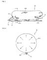
FIG. 1 shows an embodiment of an airbag according to the present invention; -
FIG. 2 is an enlarged view of part of the airbag of this embodiment; -
FIG. 3 shows the airbag of this embodiment in its inflated state; -
FIG. 4 is a sectional view taken along line a-a ofFIG. 3 ; -
FIG. 5 is an enlarged view of part of the airbag ofFIG. 3 ; -
FIG. 6 is a perspective view of a vehicle equipped with an airbag apparatus of this embodiment; -
FIG. 7 is a perspective view of a front pillar of a vehicle of this embodiment and its vicinity; -
FIG. 8 is a sectional view taken along line b-b ofFIG. 7 ; -
FIG. 9 shows the operation of theairbag apparatus 10 of this embodiment; -
FIG. 10 is a perspective view of the front pillar and its vicinity in the completion stage of inflation of the airbag of this embodiment; -
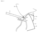
FIG. 11 is a sectional view taken along line c-c ofFIG. 10 ; and -
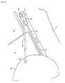
FIG. 12 is an enlarged view of a through anchor and its vicinity in the completion stage of inflation of the airbag of this embodiment. -
FIG. 1 shows anairbag 20 of this embodiment. Theairbag 20 of this embodiment is formed by folding and sewing a single base cloth, and includes a main inflatingportion 20a, a pipe connecting portion 20b, andtubular portions 20c as examples of inserting portion. The main inflatingportion 20a has a substantially elliptical shape. When inflated, the main inflatingportion 20a cushions the shock to a collision object such as a pedestrian. The pipe connecting portion 20b protrudes from the main inflatingportion 20a. Apipe 16 is inserted into the pipe connecting portion 20b, and then the pipe connecting portion 20b is caulked. Thetubular portions 20c are located on the opposite side of theairbag 20 from the shock absorbing side. Thetubular portions 20c are formed in a tubular shape so that a below-described developing position limiting means 21 can be inserted. Thetubular portions 20c are preferably provided at least on thevehicle side 20d of the main inflatingportion 20a and at the pipe connecting portion 20b so that the position can be limited throughout the length of theairbag 20. -
FIG. 2 is an enlarged view of part of theairbag 20. As shown inFIG. 2 , in the base cloth of theairbag 20, the grid consisting of thefirst yarns 201 and thesecond yarns 202 is inclined at about 45 degrees to the longitudinal direction. The term "longitudinal direction" means the direction of the length of theairbag 20, and is not limited to the direction of the greatest length but includes some slight inclination. - Next, the
airbag 20 having such a structure in its inflated condition will be shown.FIG. 3 shows theairbag 20 in its inflated state.FIG. 4 is a sectional view taken along line a-a ofFIG. 3 .FIG. 5 is an enlarged view of part of theair bag 20 in its inflated state. - When the
airbag 20 inflates, as shown inFIG. 4 , part of the main inflatingportion 20a near the pipe connecting portion 20b inflates first, in the circumferential direction. At this time, the grid consisting of thefirst yarns 201 and thesecond yarns 202 of theairbag 20 is deformed, as shown inFIG. 5 , so as to stretch in the circumferential direction and contract in the longitudinal direction. Therefore, thewhole airbag 20 inflates, as shown inFIG. 3 , so as to contract in the longitudinal direction and stretch in the circumferential direction. - Inclining the grid at about 45 degrees to the longitudinal direction makes the diameter at the time of inflation about 10% larger compared to the case where the grid is at zero degrees. Therefore, the use of the base cloth can be reduced by about 10%, and therefore the cost can be reduced. In addition, the airbag can be efficiently housed in a narrow space such as a space in a front pillar because the airbag inflates widely.
- In this embodiment, a below-described developing position limiting means 21 is passed through the
tubular portions 20c of theairbag 20. To allow theairbag 20 to stretch in the circumferential direction and contract in the longitudinal direction during inflation, theairbag 20 and the developing position limiting means 21 are not firmly fixed to each other. - Next, a state where an
airbag apparatus 10 including theairbag 20 is installed in avehicle 1 will be described. -
FIG. 6 is a perspective view of a vehicle equipped with an airbag apparatus of this embodiment.FIG. 7 is a perspective view of a front pillar of a vehicle of this embodiment and its vicinity.FIG. 8 is a sectional view taken along line b-b ofFIG. 7 . - In the figures,
reference numeral 1 denotes a vehicle,reference numeral 2 denotes a front pillar,reference numeral 3 denotes a fender,reference numeral 4 denotes a hood,reference numeral 5 denotes a roof,reference numeral 6 denotes a windshield,reference numeral 7 denotes a seal,reference numeral 10 denotes an airbag apparatus,reference numeral 11 denotes a cover,reference numeral 12 denotes a bag case,reference numeral 13 denotes an anchor,reference numeral 14 denotes a through anchor,reference numeral 15 denotes a gas generator,reference numeral 16 denotes a pipe,reference numeral 20 denotes an airbag, andreference numeral 21 denotes a developing position limiting means. - A
vehicle 1 hasfront pillars 2 that connect a member (not shown) or an engine room frame (not shown) and aroof 5. In addition, thevehicle 1 has awindshield 6 surrounded by ahood 4, theroof 5, and thefront pillars 2 and attached using aseal 7. - An
airbag apparatus 10 is housed in thewindshield 6 side of thefront pillar 2 and thefender 3 on each side. Thefront pillar 2 has afirst surface 2a that faces the outside of thevehicle 1 and asecond surface 2b that faces the windshield. On thesecond surface 2b side, anairbag 20 is folded and housed in abag case 12 together with a developingposition limiting means 21, and housed in acover 11. - The
cover 11 has a substantially L-shaped cross-sectional shape and includes an upper cover 11a and a side cover 11b, and is disposed so as to hide theairbag 20 folded on thesecond surface 2b side of thefront pillar 2. The foldedairbag 20 may be directly housed in thecover 11 without being housed in thebag case 12. - The developing position limiting means 21 is a string-like or belt-like member. One
end 21a thereof is engaged with part of the vehicle body such as the base portion of thefront pillar 2 by theanchor 13. Theother end 21b thereof is passed through aninsertion hole 14a of thethrough anchor 14 and is engaged with theair bag 20 by sewing or adhesion. For example, it is preferable to engage theother end 21b with a portion having an insertion hole provided in theairbag 20. Themiddle portion 21c thereof is passed through atubular portion 20c formed in theairbag 20, for example, by sewing. - The one
end 21a may be engaged with agas generator 15 or theairbag 20. The throughanchor 14 may have a smooth structure having, for example, a guide or a pulley so that friction does not significantly affect the developingposition limiting means 21. Although, in this embodiment, thetubular portion 20c is provided substantially throughout the length of theairbag 20 along thefront pillar 2, a plurality oftubular portions 20c may be provided at intervals. Thetubular portions 20c are preferably provided near the ends of theairbag 20 so that theairbag 20 becomes more stable. - Under the
fender 3 or thehood 4, agas generator 15 that generates gas to inflate theairbag 20 and apipe 16 that supplies the gas generated in thegas generator 15 to theairbag 20 are housed. - Next, the operation of the
airbag apparatus 10 of this embodiment will be described.FIG. 9 shows the operation of theairbag apparatus 10 of this embodiment. - The
airbag apparatus 10 in its housed state shown inFIG. 7 is activated when thevehicle 1 collides with an object (not shown) and a detecting means (not shown) detects the impact force applied to thevehicle 1, on the basis of the detection signal, for example, by a control means. -
FIG. 9 (a) shows an early stage of inflation in which theairbag apparatus 10 starts operation, gas flows from thegas generator 15 housed in thefender 3 through thepipe 16 into theairbag 20, and theairbag 20 starts to inflate. In the early stage of inflation, thefender 3 side of theairbag 20 inflates first, and thecover 11 shown inFIGS. 7 and8 opens due to the inflation pressure. -
FIG. 9 (b) shows a middle stage of inflation in which gas flows from thegas generator 15 through thepipe 16 into theairbag 20, and theairbag 20 continues to inflate. In the middle stage of inflation, theentire airbag 20 is completely exposed outside from its folded state. At this time, no tension is applied to the developing position limiting means 21, and the inflation of theairbag 20 is continued. -
FIG. 9 (c) shows a completion stage of inflation in which the inflation of theairbag 20 is completed. In the completion stage of inflation, theairbag 20 is completely inflated. The state of theairbag apparatus 10 in the completion stage of inflation will be described.
FIG. 10 is a perspective view of thefront pillar 2 and its vicinity in the completion stage of inflation.FIG. 11 is a sectional view taken along line b-b ofFIG. 10 .FIG. 12 is an enlarged view of thethrough anchor 14 and its vicinity. - In the completion stage of inflation, the
airbag 20 develops above parts of thefender 3 and thehood 4 and in front of thefront pillar 2, in the direction along thefront pillar 2. - At this time, the
other end 21b of the developing position limiting means 21 engaged with theairbag 20 is pulled in response to the inflation of theairbag 20, as shown by arrow A, away from theroof 5. Therefore, relative to the throughanchor 14, themiddle portion 21c of the developing position limiting means 21 is pulled, as shown by arrow B, toward theroof 5, and is pressed against thewindshield 6 and thefront pillar 2. As shown inFIG. 10 , theairbag 20 through which the developing position limiting means 21 is passed is also pressed against thewindshield 6 and thefront pillar 2. - It is possible to provide a plurality of developing
position limiting means 21. The form of the developing position limiting means 21 is not limited to this embodiment but any other form can be taken as long as it presses theairbag 20 against thewindshield 6 and thefront pillar 2 when theairbag 20 inflates. - Although, in this embodiment, the
gas generator 15 is housed in thefender 3, thegas generator 15 may be housed in theroof 5. In this case, it is preferable to dispose theanchor 13 in theroof 5 and the throughanchor 14 in thefender 3. - As described above, the
airbag 20 has a substantially tubular shape, and stretches in the circumferential direction and contracts in the longitudinal direction when inflating compared to before the inflation. Therefore, before the inflation, the airbag can be housed in a thin state in the direction of the width of the vehicle in a small space. After the inflation, the airbag extends in the direction of the width of the vehicle, and therefore the shock-absorbing area can be extended. - In addition, the base cloth of the
airbag 20 is made of a grid consisting offirst yarns 201 andsecond yarns 202 intersecting with each other, and the grid consisting of thefirst yarns 201 and thesecond yarns 202 is inclined at about 45 degrees to the longitudinal direction of theairbag 20. Therefore, theairbag 20 can widely extend in the direction of the width of the vehicle. - According to the airbag apparatus of the present invention, the airbag has a substantially tubular shape, and stretches in the circumferential direction and contracts in the longitudinal direction when inflating compared to before the inflation. Therefore, before the inflation, the airbag can be housed in a thin state in the direction of the width of the vehicle in a small space. After the inflation, the airbag extends in the direction of the width of the vehicle, and therefore the shock-absorbing area can be extended.
- In addition, the base cloth of the airbag is made of a grid consisting of first yarns and second yarns intersecting with each other, and the grid consisting of the first yarns and the second yarns is inclined at about 45 degrees to the longitudinal direction of the airbag. Therefore, the extension in the direction of the width of the vehicle can be maximized.
Claims (2)
- An airbag apparatus comprising:an airbag;an inflator that discharges gas into the airbag;a detecting means that detects a collision; anda control means that activates the inflator in response to a signal from the detecting means,wherein the airbag disposed along a front pillar is inflated outside a vehicle, and
the airbag has a substantially tubular shape, and stretches in the circumferential direction and contracts in the longitudinal direction when inflating compared to before the inflation. - The airbag apparatus according to Claim 1, wherein the base cloth of the airbag is made of a grid consisting of first yarns and second yarns intersecting with each other, and the grid consisting of the first yarns and the second yarns is inclined at about 45 degrees to the longitudinal direction of the airbag.
Applications Claiming Priority (1)
| Application Number | Priority Date | Filing Date | Title |
|---|---|---|---|
| JP2007268682A JP5033571B2 (en) | 2007-10-16 | 2007-10-16 | Airbag device |
Publications (3)
| Publication Number | Publication Date |
|---|---|
| EP2050634A2 true EP2050634A2 (en) | 2009-04-22 |
| EP2050634A3 EP2050634A3 (en) | 2010-05-12 |
| EP2050634B1 EP2050634B1 (en) | 2011-07-06 |
Family
ID=40297952
Family Applications (1)
| Application Number | Title | Priority Date | Filing Date |
|---|---|---|---|
| EP08164314A Ceased EP2050634B1 (en) | 2007-10-16 | 2008-09-15 | Airbag apparatus |
Country Status (2)
| Country | Link |
|---|---|
| EP (1) | EP2050634B1 (en) |
| JP (1) | JP5033571B2 (en) |
Families Citing this family (1)
| Publication number | Priority date | Publication date | Assignee | Title |
|---|---|---|---|---|
| US11491950B2 (en) * | 2021-03-01 | 2022-11-08 | Ford Global Technologies, Llc | Vehicle external airbag |
Citations (2)
| Publication number | Priority date | Publication date | Assignee | Title |
|---|---|---|---|---|
| JP2002283939A (en) | 2001-03-29 | 2002-10-03 | Toyota Motor Corp | Pedestrian protection airbag device |
| JP2004196132A (en) | 2002-12-18 | 2004-07-15 | Takata Corp | Airbag device, motorcycle with airbag device, and producing method of airbag device |
Family Cites Families (4)
| Publication number | Priority date | Publication date | Assignee | Title |
|---|---|---|---|---|
| DE29605897U1 (en) * | 1996-03-29 | 1996-07-25 | Trw Repa Gmbh | Gas bag |
| JP2004338676A (en) * | 2003-05-19 | 2004-12-02 | Takata Corp | Outer surface development type air bag device |
| JP4175338B2 (en) * | 2005-04-20 | 2008-11-05 | トヨタ自動車株式会社 | Airbag device |
| DE102006033670B4 (en) * | 2005-07-26 | 2011-08-25 | Honda Motor Co., Ltd. | Vehicle with collision object protection device |
-
2007
- 2007-10-16 JP JP2007268682A patent/JP5033571B2/en not_active Expired - Fee Related
-
2008
- 2008-09-15 EP EP08164314A patent/EP2050634B1/en not_active Ceased
Patent Citations (2)
| Publication number | Priority date | Publication date | Assignee | Title |
|---|---|---|---|---|
| JP2002283939A (en) | 2001-03-29 | 2002-10-03 | Toyota Motor Corp | Pedestrian protection airbag device |
| JP2004196132A (en) | 2002-12-18 | 2004-07-15 | Takata Corp | Airbag device, motorcycle with airbag device, and producing method of airbag device |
Also Published As
| Publication number | Publication date |
|---|---|
| EP2050634B1 (en) | 2011-07-06 |
| JP5033571B2 (en) | 2012-09-26 |
| EP2050634A3 (en) | 2010-05-12 |
| JP2009096276A (en) | 2009-05-07 |
Similar Documents
| Publication | Publication Date | Title |
|---|---|---|
| US7997614B2 (en) | Airbag device | |
| US9539974B2 (en) | Airbag device and covering method for airbag body | |
| KR100232011B1 (en) | Airbag for side impact mitigation of seat-mounted type | |
| EP0957010A2 (en) | Structure for placement of head protecting air bag apparatus | |
| KR101068648B1 (en) | Curtain airbags and vehicles | |
| EP2390144A1 (en) | Curtain airbag | |
| JPH11240407A (en) | Safety device for vehicle | |
| EP2050633A2 (en) | Airbag apparatus | |
| JP2003509285A (en) | Mechanically deployable device shield | |
| US8672345B2 (en) | Curtain airbag for a motor vehicle | |
| KR100990035B1 (en) | Car passenger airbag cushion with tether holder | |
| CN116261537A (en) | Airbag device for vehicle seat and vehicle seat with airbag device | |
| EP2050632B1 (en) | Airbag apparatus | |
| KR102885993B1 (en) | Airbag apparatus for vehicle | |
| EP2050634B1 (en) | Airbag apparatus | |
| EP2050635B1 (en) | Airbag apparatus | |
| JP2009083755A (en) | Head protection airbag device | |
| US12097819B2 (en) | Curtain airbag module | |
| US6964431B2 (en) | Loop cord slide device for airbag | |
| JP4820475B2 (en) | Air bag folding method, air bag device assembling method, and air bag | |
| JP5145173B2 (en) | Airbag device | |
| JP4906667B2 (en) | Airbag device | |
| JP2006151075A (en) | Head protection air bag device | |
| KR100491046B1 (en) | Apparatus for adjustably pulling tether | |
| US7784821B2 (en) | Device for decreasing peak pressure of airbag |
Legal Events
| Date | Code | Title | Description |
|---|---|---|---|
| PUAI | Public reference made under article 153(3) epc to a published international application that has entered the european phase |
Free format text: ORIGINAL CODE: 0009012 |
|
| AK | Designated contracting states |
Kind code of ref document: A2 Designated state(s): AT BE BG CH CY CZ DE DK EE ES FI FR GB GR HR HU IE IS IT LI LT LU LV MC MT NL NO PL PT RO SE SI SK TR |
|
| AX | Request for extension of the european patent |
Extension state: AL BA MK RS |
|
| PUAL | Search report despatched |
Free format text: ORIGINAL CODE: 0009013 |
|
| AK | Designated contracting states |
Kind code of ref document: A3 Designated state(s): AT BE BG CH CY CZ DE DK EE ES FI FR GB GR HR HU IE IS IT LI LT LU LV MC MT NL NO PL PT RO SE SI SK TR |
|
| AX | Request for extension of the european patent |
Extension state: AL BA MK RS |
|
| RIC1 | Information provided on ipc code assigned before grant |
Ipc: B60R 21/213 20060101ALI20100406BHEP Ipc: B60R 21/34 20060101AFI20090205BHEP |
|
| 17P | Request for examination filed |
Effective date: 20101018 |
|
| AKX | Designation fees paid |
Designated state(s): DE GB |
|
| GRAP | Despatch of communication of intention to grant a patent |
Free format text: ORIGINAL CODE: EPIDOSNIGR1 |
|
| RIC1 | Information provided on ipc code assigned before grant |
Ipc: B60R 21/34 20110101AFI20110119BHEP Ipc: B60R 21/213 20110101ALI20110119BHEP |
|
| GRAS | Grant fee paid |
Free format text: ORIGINAL CODE: EPIDOSNIGR3 |
|
| GRAA | (expected) grant |
Free format text: ORIGINAL CODE: 0009210 |
|
| AK | Designated contracting states |
Kind code of ref document: B1 Designated state(s): DE GB |
|
| REG | Reference to a national code |
Ref country code: GB Ref legal event code: FG4D |
|
| REG | Reference to a national code |
Ref country code: DE Ref legal event code: R096 Ref document number: 602008008073 Country of ref document: DE Effective date: 20110825 |
|
| PLBE | No opposition filed within time limit |
Free format text: ORIGINAL CODE: 0009261 |
|
| STAA | Information on the status of an ep patent application or granted ep patent |
Free format text: STATUS: NO OPPOSITION FILED WITHIN TIME LIMIT |
|
| 26N | No opposition filed |
Effective date: 20120411 |
|
| REG | Reference to a national code |
Ref country code: DE Ref legal event code: R097 Ref document number: 602008008073 Country of ref document: DE Effective date: 20120411 |
|
| PGFP | Annual fee paid to national office [announced via postgrant information from national office to epo] |
Ref country code: GB Payment date: 20130911 Year of fee payment: 6 |
|
| GBPC | Gb: european patent ceased through non-payment of renewal fee |
Effective date: 20140915 |
|
| PG25 | Lapsed in a contracting state [announced via postgrant information from national office to epo] |
Ref country code: GB Free format text: LAPSE BECAUSE OF NON-PAYMENT OF DUE FEES Effective date: 20140915 |
|
| REG | Reference to a national code |
Ref country code: DE Ref legal event code: R082 Ref document number: 602008008073 Country of ref document: DE Representative=s name: VOSSIUS & PARTNER PATENTANWAELTE RECHTSANWAELT, DE Ref country code: DE Ref legal event code: R081 Ref document number: 602008008073 Country of ref document: DE Owner name: JOYSON SAFETY SYSTEMS JAPAN K.K., JP Free format text: FORMER OWNER: TAKATA CORP., TOKIO/TOKYO, JP |
|
| PGFP | Annual fee paid to national office [announced via postgrant information from national office to epo] |
Ref country code: DE Payment date: 20180920 Year of fee payment: 11 |
|
| REG | Reference to a national code |
Ref country code: DE Ref legal event code: R119 Ref document number: 602008008073 Country of ref document: DE |
|
| PG25 | Lapsed in a contracting state [announced via postgrant information from national office to epo] |
Ref country code: DE Free format text: LAPSE BECAUSE OF NON-PAYMENT OF DUE FEES Effective date: 20200401 |