EP2050542A1 - Gas burning type driving tool - Google Patents
Gas burning type driving tool Download PDFInfo
- Publication number
- EP2050542A1 EP2050542A1 EP07791921A EP07791921A EP2050542A1 EP 2050542 A1 EP2050542 A1 EP 2050542A1 EP 07791921 A EP07791921 A EP 07791921A EP 07791921 A EP07791921 A EP 07791921A EP 2050542 A1 EP2050542 A1 EP 2050542A1
- Authority
- EP
- European Patent Office
- Prior art keywords
- striking
- cylinder
- combustion chamber
- valve
- spring
- Prior art date
- Legal status (The legal status is an assumption and is not a legal conclusion. Google has not performed a legal analysis and makes no representation as to the accuracy of the status listed.)
- Granted
Links
Images




Classifications
-
- B—PERFORMING OPERATIONS; TRANSPORTING
- B25—HAND TOOLS; PORTABLE POWER-DRIVEN TOOLS; MANIPULATORS
- B25C—HAND-HELD NAILING OR STAPLING TOOLS; MANUALLY OPERATED PORTABLE STAPLING TOOLS
- B25C1/00—Hand-held nailing tools; Nail feeding devices
- B25C1/08—Hand-held nailing tools; Nail feeding devices operated by combustion pressure
-
- B—PERFORMING OPERATIONS; TRANSPORTING
- B25—HAND TOOLS; PORTABLE POWER-DRIVEN TOOLS; MANIPULATORS
- B25C—HAND-HELD NAILING OR STAPLING TOOLS; MANUALLY OPERATED PORTABLE STAPLING TOOLS
- B25C1/00—Hand-held nailing tools; Nail feeding devices
- B25C1/08—Hand-held nailing tools; Nail feeding devices operated by combustion pressure
- B25C1/10—Hand-held nailing tools; Nail feeding devices operated by combustion pressure generated by detonation of a cartridge
-
- B—PERFORMING OPERATIONS; TRANSPORTING
- B25—HAND TOOLS; PORTABLE POWER-DRIVEN TOOLS; MANIPULATORS
- B25C—HAND-HELD NAILING OR STAPLING TOOLS; MANUALLY OPERATED PORTABLE STAPLING TOOLS
- B25C1/00—Hand-held nailing tools; Nail feeding devices
- B25C1/08—Hand-held nailing tools; Nail feeding devices operated by combustion pressure
- B25C1/10—Hand-held nailing tools; Nail feeding devices operated by combustion pressure generated by detonation of a cartridge
- B25C1/18—Details and accessories, e.g. splinter guards, spall minimisers
-
- F—MECHANICAL ENGINEERING; LIGHTING; HEATING; WEAPONS; BLASTING
- F01—MACHINES OR ENGINES IN GENERAL; ENGINE PLANTS IN GENERAL; STEAM ENGINES
- F01B—MACHINES OR ENGINES, IN GENERAL OR OF POSITIVE-DISPLACEMENT TYPE, e.g. STEAM ENGINES
- F01B11/00—Reciprocating-piston machines or engines without rotary main shaft, e.g. of free-piston type
- F01B11/04—Engines combined with reciprocatory driven devices, e.g. hammers
Definitions
- the gas combustion type striking tool is necessarily equipped with a battery so as to ignite the ignition plug and rotate the fan. Therefore, by using this battery, the cylinder valve can be electrically operated. Therefore, it is unnecessary to provide another electric power source. Accordingly, the entire structure can be made compact. Since the motor, the pinion and so forth are accommodated in the tool body, these parts are not affected by dust generated at the time of working. Therefore, failure is seldom caused.
- the partitioning portion 16, which partitions the striking cylinder 5 and the combustion chamber 9, and the valve mechanism, which opens and closes the partitioning portion 16, are provided in an upper portion of the striking cylinder 5.
- the cylinder valve 18 is formed into an annular shape and slidably arranged along an outside face of the striking cylinder 5 including the opening portion 21 so that the opening portions 21, which are formed at regular intervals in an upper end side portion of the striking cylinder 5, can be opened and closed.
- the cylinder valve 18 is normally urged by the spring 17 in a direction in which the opening portion 21 is closed.
- a spring force of the spring 17 is set at a value at which a closed state of the cylinder valve 18 can not be maintained when the internal pressure in the combustion chamber 9 is increased by combustion.
- the combustion gas is cooled and the pressure in the upper portion of the striking piston 6 is decreased. Therefore, as shown in Fig. 3 , the cylinder valve 18 is moved upward and the opening portion 21 is closed. At the same time, the check valve 20 is opened by a pressure difference between the upper portion and the lower portion of the partitioning portion 16. Therefore, the striking piston 6 is returned upward. The pressure in the striking cylinder 5 is released from the upper opening portion 22 into the combustion chamber 9. Accordingly, the striking piston 6 can be positively returned to the top dead center.
- the contact member 23 is separated from the workpiece to which a nail is struck, as shown in Fig. 1 , the contact member 23 and the link member are relatively moved downward with respect to the tool body 1. Accordingly, the movable sleeve 10 is also moved downward and the combustion chamber 9 is opened and fresh air enters from an upper portion. Combustion gas is discharged form a lower portion. In this way, preparation is made for the next striking operation.
- the partitioning portion 16 is provided which partitions the striking cylinder 5 and the combustion chamber 9.
- the valve mechanism for opening and closing this partitioning portion 16 includes: a cylinder valve 18 normally urged by a spring so that the combustion chamber 9 and the striking cylinder 5 can be closed, opened against a spring force of the spring 17 when an internal pressure in the combustion chamber 9 is higher than an internal pressure in the striking cylinder 5; and a check valve 20 normally urged by a spring so that the combustion chamber 9 and the striking cylinder 5 can be closed, opened against the spring force when the internal pressure in the striking cylinder 5 is higher than the internal pressure in the combustion chamber 9.
- a volume in the combustion chamber 9 can be always kept constant irrespective of the position of the striking piston and the mixed gas in the combustion chamber 9 can be maintained at a constant appropriate concentration. Accordingly, even when the striking piston 6 can not be sufficiently returned to the initial position, a predetermined pressure is given to the striking piston 6 so that the striking piston 6 can be moved to the bottom dead center and at the time of cooling, the striking piston 6 can be returned to the top dead center again.
- the lockout bar 25 is operated integrally with the contact member 23.
- An upper end of the lockout bar 25 is connected to a lower end of the movable sleeve 10.
- the protruding portion 31, which is a pushing member, is formed on the hook member 24 side of the intermediate portion of the lockout bar 25, the protruding portion 31, which is a pushing member, is formed. Accordingly, the protruding portion 31 is moved in the vertical direction together with the lockout bar 25. When the protruding portion 31 is moved upward, it pushes a back of the hook base 26 so as to make an engagement.
- the U-shaped lock bar 32 is attached to a lower portion of the cylinder valve 18.
- the combustion gas is cooled and an upper portion of the striking piston 6 is decompressed and the cylinder valve 18 is maintained being opened. Therefore, the striking piston 6 can be positively returned to the top dead center.
- the contact member 23 is relatively moved downward with respect to the tool body 1 and the protruding portion 31 is also moved downward. Therefore, as shown in Fig. 8 , a pushing force given to the hook base 26 is released and the hook member 24 is inclined backward by the coil spring 37 and the hook 27 is disengaged from the lock bar 32. Accordingly, the cylinder valve 18 is moved upward by the spring 17 and closes the opening portion 21. Then, fresh air enters the combustion chamber 9 and the combustion gas is discharged from a lower portion. In this way, preparation is made for the next striking operation.
- the hook member 24 is provided which is linked with the contact member 23 normally protruding from the nose portion 4 and relatively moving upward with respect to the tool body 1 when the contact member 23 is pressed against the workpiece to which the nail is pressed, at the time of striking a nail.
- the hook member 24 is engaged with the opened cylinder valve 18 so as to maintain an open state.
- the contact member 23 is moved downward, an engagement of the hook member 24 with the cylinder valve 18 is released. Due to the above structure, the cylinder valve 18 is mechanically operated by the hook member 24. Accordingly, the opening and closing operation can be positively executed.
- the cylinder valve 18 can be closed as shown in Fig. 9 and opened as shown in Fig. 10 . Accordingly, a period of time from the time of one ignition to the time of returning to the top dead center after the striking piston 6 has been reciprocated once is previously measured and set. Then, the electric motor 33 is operated being a little delayed from the ignition timing so as to open the cylinder valve 18. At the point of time at which the setting time has passed from the ignition time, the electric motor 33 is reversed so that the cylinder valve 18 can be closed.
- the present invention is applicable to a gas combustion type striking tool for striking a fastener such as a nail or a struck screw, to which power is supplied by combustion.
Landscapes
- Engineering & Computer Science (AREA)
- Mechanical Engineering (AREA)
- Chemical & Material Sciences (AREA)
- Combustion & Propulsion (AREA)
- General Engineering & Computer Science (AREA)
- Portable Nailing Machines And Staplers (AREA)
- Formation Of Insulating Films (AREA)
- Sampling And Sample Adjustment (AREA)
Abstract
Description
- The present invention relates to a gas combustion type striking tool for striking a fastener such as a nail or a struck screw, to which power is supplied by combustion. More particularly, the present invention relates to a valve device for controlling an opening and closing motion of a partitioning portion that partitions a striking cylinder and a combustion chamber.
- In a gas combustion type striking tool, mixed gas obtained when combustible gas and air are agitated and mixed by a fan in a combustion chamber is ignited and explosively burned, and the gas pressure of the thus obtained combustion gas is supplied into a striking cylinder so as to drive a striking piston. (Refer to
JP-B-04-048589 - In the conventional gas combustion type striking tool, the combustion chamber and the striking cylinder are integrally continuous. Therefore, for example, when the striking piston is returned upward after a striking operation has been completed and the striking piston is returned only to an intermediate position for some reasons, a volume of the combustion chamber is expanded to a position to which the striking piston is returned. Even when the volume of the combustion chamber is expanded, a volume of air and mixed gas to be supplied is constant. Therefore, the fuel is diluted and it becomes impossible to ignite the mixed gas in some cases. In this case, it is necessary to disassemble the tool and return the striking piston to a predetermined position with the worker's hands. On the assumption of the occurrence of such a case, a volume of fuel larger than an appropriate volume of fuel for combustion must be always supplied to the tool so that the mixed gas can be ignited even in the case where the volume of the combustion chamber has been expanded.
- In the case where air is supplied to the combustion chamber being supercharged by an air compressor so as to increase an internal pressure of the combustion chamber and to obtain a higher output, there is a possibility that the striking piston can not be maintained at a predetermined top dead center position and lowered by the supercharging pressure. Accordingly, in order to strongly hold the striking piston, it is necessary to strengthen a force to return the striking piston upward. However, a returning motion of the striking piston is made by a pressure difference between the decompression caused by the cooling of the combustion chamber after the completion of combustion and the pressure acting on a lower face of the striking piston. Therefore, the decompression of the supercharged combustion gas after the completion of combustion adversely acts on the returning motion of the striking piston.
- One or more embodiments of the present invention provides a valve device of a combustion chamber in a gas combustion type striking tool in which fuel can be supplied into a combustion chamber at an appropriate concentration and further it is possible to positively prevent a striking piston from being lowered by a supercharging pressure.
- According to a first aspect of the present invention, in a gas combustion type striking tool of one or more embodiments of the present invention, a striking piston is slidably provided in a striking cylinder arranged in a tool body. A combustion chamber provided in an upper portion of the striking cylinder is can be opened and closed. When mixed gas, in which combustible gas and air are mixed with each other, is explosively burned in the combustion chamber being ignited by an ignition plug arranged in a cylinder head, high gas pressure acts on the striking piston so that the striking piston is driven being given an impact force. Then, a driver connected to a lower face side of the striking piston strikes a fastener from a nose portion provided in a lower portion of the tool body. At an upper end of the striking cylinder, a partitioning portion for partitioning the striking cylinder and the combustion chamber is provided. A valve mechanism for opening and closing this partitioning portion is provided. At the time of driving the striking piston and at the time of returning of the striking piston after a fastener has been stricken, the valve mechanism is opened.
- According to a second aspect of the present invention, in the gas combustion type striking tool of the first aspect, the valve mechanism includes: a cylinder valve normally urged by a spring so that the combustion chamber and the striking cylinder are closed, and opened against a spring force of the spring when an internal pressure in the combustion chamber is higher than an internal pressure in the striking cylinder; and a check valve normally urged by a spring so that the combustion chamber and the striking cylinder is closed and opened against the spring force when the internal pressure in the striking cylinder is higher than the internal pressure in the combustion chamber.
- According to a third aspect of the present invention, in the gas combustion type striking tool of the first aspect, the valve mechanism includes: a cylinder valve normally urged by a spring so that the combustion chamber and the striking cylinder is closed, opened against a spring force of the spring when an internal pressure in the combustion chamber is higher than an internal pressure in the striking cylinder; a hook member capable of engaging with the cylinder valve; and a pushing member for pushing the hook member at the time of striking so that the hook member is engaged with the cylinder valve, separating from the hookmember after the completion of striking.
- According to a fourth aspect of the present invention, in the gas combustion type striking tool of the first aspect, the valve mechanism includes a cylinder valve for opening and closing the combustion chamber and the striking cylinder, wherein the valve mechanism electrically controls an operation of the cylinder valve so that the cylinder valve can be linked with the combustion in the combustion chamber and the returning motion of the striking cylinder after the completion of striking.
- According to the gas combustion type striking tool of the first aspect, the partitioning portion for partitioning the striking cylinder and the combustion chamber is provided at an upper end of the striking cylinder and the valve mechanism for opening and closing this partitioning portion is provided. At the time of driving the striking piston and at the time of returning of the striking piston after the completion of striking the fastener, the valve mechanism is operated being opened. Therefore, at the time of driving the striking piston, the combustion chamber and the striking cylinder are communicated with each other. Therefore, gas pressure generated in the combustion chamber is supplied into the striking cylinder. Accordingly, the striking cylinder is driven. After the completion of striking, the combustion chamber and the striking cylinder are communicated with each other. Therefore, the striking piston can be positively returned to the initial position.
- As described above, by the partitioning portion, a volume in the combustion chamber can be always kept constant irrespective of the position of the striking piston and the mixed gas in the combustion chamber can be maintained at a constant appropriate concentration. Accordingly, even when the striking piston can not be sufficiently returned to the initial position, a predetermined pressure is given to the striking piston so that the striking piston can be moved to the bottom dead center and at the time of cooling, the striking piston can be returned to the top dead center again.
- In the case where the combustion chamber is supercharged by using a supercharger, although pressure in the combustion chamber is increased, the valve mechanism is not operated and the valve is not opened. Accordingly, the striking piston does not receive pressure from the combustion chamber. Therefore, it is possible to positively prevent the striking piston from being lowered by the supercharging pressure.
- According to the gas combustion type striking tool of the second aspect, the valve mechanism for opening and closing the partitioning portion, which partitions the striking cylinder and the combustion chamber, includes: a cylinder valve normally urged by a spring so that the combustion chamber and the striking cylinder can be closed and opened against a spring force of the spring when an internal pressure in the combustion chamber is higher than an internal pressure in the striking cylinder; and a check valve normally urged by a spring so that the combustion chamber and the striking cylinder can be closed and opened against the spring force when the internal pressure in the striking cylinder is higher than the internal pressure in the combustion chamber. Therefore, the valve structure is simple and the number of parts of the valve structure can be reduced to the minimum.
- According to the gas combustion type striking tool of the third aspect, the valve mechanism includes: a cylinder valve normally urged by a spring so that the combustion chamber and the striking cylinder can be closed and opened against a spring force of the spring when an internal pressure in the combustion chamber is higher than an internal pressure in the striking cylinder; a hook member capable of engaging with the cylinder valve; and a pushing member for pushing the hook member at the time of striking so that the hook member can be engaged with the cylinder valve and separating from the hook member after the completion of striking. Accordingly, at the time of striking, the hook member engages with the cylinder valve, and, after the completion of striking, the engagement is released. Accordingly, since the cylinder valve is mechanically operated by the hook member, the valve can be positively opened and closed.
- According to the gas combustion type striking tool of the fourth aspect, the valve mechanism electrically controls an operation of the cylinder valve so that the cylinder valve can be linked with the combustion in the combustion chamber and the returning motion of the striking cylinder after the completion of striking by the striking cylinder. Therefore, a period of time, in which the striking piston is once reciprocated from one ignition time to the return to the top dead center, is previously measured and the cylinder valve is electrically opened being a little delayed from the ignition time and the cylinder valve can be electrically closed at the point of time at which a predetermined setting time has passed from the ignition time.
- The gas combustion type striking tool is necessarily equipped with a battery so as to ignite the ignition plug and rotate the fan. Therefore, by using this battery, the cylinder valve can be electrically operated. Therefore, it is unnecessary to provide another electric power source. Accordingly, the entire structure can be made compact. Since the motor, the pinion and so forth are accommodated in the tool body, these parts are not affected by dust generated at the time of working. Therefore, failure is seldom caused.
- Other aspects and advantages of the invention will be apparent from the following description, the drawings and the claims.
-
- [
Fig. 1] Fig. 1 is a longitudinal sectional view showing a gas combustion type nailing machine of a first exemplary embodiment. - [
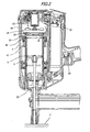
Fig. 2] Fig. 2 is a longitudinal sectional view showing a primary portion at the time of nailing executed by the above gas combustion type nailing machine. - [
Fig. 3] Fig. 3 is a longitudinal sectional view showing an operation form after the completion of nailing executed by the above gas combustion type nailing machine. - [
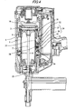
Fig. 4] Fig. 4 is a longitudinal sectional view showing an initial state of a valve mechanism in a second exemplary embodiment. - [
Fig. 5] Fig. 5 is a longitudinal sectional view showing a primary portion of a state in which a contact member is pushed into a workpiece into which a nail is struck. - [
Fig. 6] Fig. 6 is a longitudinal sectional view showing a primary portion at the time of nailing. - [
Fig. 7] Fig. 7 is a longitudinal sectional view showing a primary portion at the time of the completion of nailing. - [
Fig. 8] Fig. 8 is a longitudinal sectional view showing a primary portion in which a form of operation after the completion of nailing is shown. - [
Fig. 9] Fig. 9 is a longitudinal sectional view showing an initial state of a valve mechanism in a third exemplary embodiment. - [
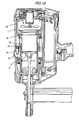
Fig. 10] Fig. 10 is a longitudinal sectional view showing a primary portion at the time of nailing. -
- 4
- Nose portion
- 5
- Striking cylinder
- 6
- Striking piston
- 9
- Combustion chamber
- 8
- Cylinder head
- 10
- Movable sleeve
- 16
- Partitioning portion
- 18
- Cylinder valve
- 20
- Check valve
- In
Fig. 1 ,reference numeral 1 designates a tool body of a gas combustion type striking tool (a nailing machine). Thegrip 2 and themagazine 3 are connected to thistool body 1 and the striking piston-cylinder mechanism is provided in thetool body 1. In a lower portion of thetool body 1, thenose portion 4, from which a fastener is struck, is provided. - The striking piston-cylinder mechanism is composed in such a manner that the
striking piston 6 is slidably accommodated in thestriking cylinder 5 and thedriver 7 is integrally connected to a lower portion of thestriking piston 6. - Between an upper portion of the
striking cylinder 5 and thecylinder head 8 arranged inside of the upper portion of thetool body 1, the cylindricalmovable sleeve 10 is arranged being capable of moving in the vertical direction. When themovable sleeve 10 is moved upward and contacted with a lower face of thecylinder head 8, theclosed combustion chamber 9, the upper portion of which is closed by thecylinder head 8 and the lower portion of which is closed by thestriking cylinder 5 and thestriking piston 6, is formed in themovable sleeve 10. - The
injection nozzle 12 communicated with thegas container 11 and theignition plug 13 for igniting mixed gas so as to burn it are arranged in thecylinder head 8. In an upper portion of thetool body 1, therotary fan 14 is arranged which agitates combustible gas injected into thecombustion chamber 9 and mixes the combustible gas with air so as to generate mixed gas of a predetermined air/fuel ratio.Reference numeral 15 designates a motor for the fan. - In this connection, the partitioning
portion 16, which partitions thestriking cylinder 5 and thecombustion chamber 9, and the valve mechanism, which opens and closes thepartitioning portion 16, are provided in an upper portion of thestriking cylinder 5. - The valve mechanism includes: a
cylinder valve 18 which is normally urged by thespring 17 so that it can close thecombustion chamber 9 and thestriking cylinder 5 and opened against a spring force of thespring 17 when an internal pressure in thecombustion chamber 9 is higher than an internal pressure in thestriking cylinder 5; and acheck valve 20 which is normally urged by the spring so that thecombustion chamber 9 and thestriking cylinder 5 can be closed and opened only when the internal pressure in thestriking cylinder 5 is higher than the internal pressure in thecombustion chamber 9. - The
cylinder valve 18 is formed into an annular shape and slidably arranged along an outside face of thestriking cylinder 5 including the openingportion 21 so that the openingportions 21, which are formed at regular intervals in an upper end side portion of thestriking cylinder 5, can be opened and closed. Thecylinder valve 18 is normally urged by thespring 17 in a direction in which theopening portion 21 is closed. A spring force of thespring 17 is set at a value at which a closed state of thecylinder valve 18 can not be maintained when the internal pressure in thecombustion chamber 9 is increased by combustion. - The
upper opening portion 22 is formed in thepartitioning portion 16 and thecheck valve 20, which is operated by a leaf spring, is arranged in theupper opening portion 22. By the action of thischeck valve 20, theupper opening portion 22 is normally urged by a spring force so that thecombustion chamber 9 and thestriking cylinder 5 can be closed. Only when an internal pressure in thestriking cylinder 5 is higher than an internal pressure in thecombustion chamber 9, theupper opening portion 22 is opened. - In this connection, the
contact member 23 is arranged so that it can be slid in the nailing direction along thenose portion 4. Thetip portion 23a of thecontact member 23 is urged by thespring 19 so that it can be normally protruded from thenose portion 4. An upper portion of thecontact member 23 is connected to a lower end portion of themovable sleeve 10 through a link member not shown. - In the above structure, when a nail is struck, as shown in
Fig. 2 , thecontact member 23 is strongly pressed against the workpiece P to which the nail is struck and thecontact member 23 and the link member are relatively moved upward with respect to thetool body 1. Accordingly, themovable sleeve 10 is moved upward until it comes into contact with thecylinder head 8 and theclosed combustion chamber 9 is formed. At the same time, combustible gas is injected into thecombustion chamber 9 from theinjection nozzle 12 and therotary fan 14 is rotated so as to agitate and mix the combustible gas and air. After that, thetrigger 29 is pulled and theignition plug 13 is ignited so as to burn the combustible gas explosively. Due to the foregoing, the internal pressure in thecombustion chamber 9 is suddenly raised. Accordingly, thecylinder valve 18 is lowered against a spring force of thespring 17 and gas of high pressure is supplied from the openingportion 21 into thestriking cylinder 5 and thestriking piston 6 is driven. - On the other hand, after the striking operation has been completed, the combustion gas is cooled and the pressure in the upper portion of the
striking piston 6 is decreased. Therefore, as shown inFig. 3 , thecylinder valve 18 is moved upward and the openingportion 21 is closed. At the same time, thecheck valve 20 is opened by a pressure difference between the upper portion and the lower portion of thepartitioning portion 16. Therefore, thestriking piston 6 is returned upward. The pressure in thestriking cylinder 5 is released from theupper opening portion 22 into thecombustion chamber 9. Accordingly, thestriking piston 6 can be positively returned to the top dead center. After that, when thecontact member 23 is separated from the workpiece to which a nail is struck, as shown inFig. 1 , thecontact member 23 and the link member are relatively moved downward with respect to thetool body 1. Accordingly, themovable sleeve 10 is also moved downward and thecombustion chamber 9 is opened and fresh air enters from an upper portion. Combustion gas is discharged form a lower portion. In this way, preparation is made for the next striking operation. - As described above, the partitioning
portion 16 is provided which partitions thestriking cylinder 5 and thecombustion chamber 9. The valve mechanism for opening and closing thispartitioning portion 16 includes: acylinder valve 18 normally urged by a spring so that thecombustion chamber 9 and thestriking cylinder 5 can be closed, opened against a spring force of thespring 17 when an internal pressure in thecombustion chamber 9 is higher than an internal pressure in thestriking cylinder 5; and acheck valve 20 normally urged by a spring so that thecombustion chamber 9 and thestriking cylinder 5 can be closed, opened against the spring force when the internal pressure in thestriking cylinder 5 is higher than the internal pressure in thecombustion chamber 9. As described above, a volume in thecombustion chamber 9 can be always kept constant irrespective of the position of the striking piston and the mixed gas in thecombustion chamber 9 can be maintained at a constant appropriate concentration. Accordingly, even when thestriking piston 6 can not be sufficiently returned to the initial position, a predetermined pressure is given to thestriking piston 6 so that thestriking piston 6 can be moved to the bottom dead center and at the time of cooling, thestriking piston 6 can be returned to the top dead center again. - In the case where the
combustion chamber 9 is supercharged by using a supercharger, pressure in thecombustion chamber 9 is raised, however, thecylinder valve 18 is not opened in this case. Accordingly, thestriking piston 6 does not receive pressure from thecombustion chamber 9. Therefore, it is possible to positively prevent thestriking piston 6 from being lowered by the supercharging pressure. - Further, since the structure is simple, the number of parts can be reduced to the minimum.
-
Figs. 4 to 8 are views showing a valve mechanism of a second exemplary embodiment. The same reference marks are used to indicate the same parts in the first and the second exemplary embodiments. - This valve mechanism includes: a
cylinder valve 18 shown in the above description; ahook member 24 provided outside thestriking cylinder 5; and alockout bar 25 linked with thecontact member 23. - The
hook member 24 is composed in such a manner that thehook base 26 and thehook 27 are connected to each other by thehelical spring 28. Thishook member 24 is pivotally supported by thesame spindle 30 provided in thetool body 1. Thehook base 26 is urged so that an upper portion of thehook base 26 can fall backward by an action of thecoil spring 37. Thehook base 26 and thehook 27 are operated by thehelical spring 28 being integrated with each other into one body. An upper portion of thehook member 24 is normally inclined backward. - The
lockout bar 25 is operated integrally with thecontact member 23. An upper end of thelockout bar 25 is connected to a lower end of themovable sleeve 10. On thehook member 24 side of the intermediate portion of thelockout bar 25, the protrudingportion 31, which is a pushing member, is formed. Accordingly, the protrudingportion 31 is moved in the vertical direction together with thelockout bar 25. When the protrudingportion 31 is moved upward, it pushes a back of thehook base 26 so as to make an engagement. - In this connection, the
U-shaped lock bar 32 is attached to a lower portion of thecylinder valve 18. - In the above structure, when a nail is struck, as shown in
Fig. 5 , thecontact member 23 is strongly pressed against the workpiece P to which the nail is struck. Due to the foregoing, themovable sleeve 10 is moved upward until it comes into contact with thecylinder head 8. Due to the foregoing, theclosed combustion chamber 9 is formed. At the same time, combustible gas is injected from theinjection nozzle 12 into thecombustion chamber 9 and therotary fan 14 is rotated so as to agitate and mix the combustible gas with air. At the same time, thelockout bar 25 is moved upward together with thecontact member 23. Accordingly, the protrudingportion 31 is engaged with the back of thehook base 26 of thehook member 24. Therefore, thehook member 24 is rotated on thestriking cylinder 5 side round thespindle 30. - As shown in
Fig. 6 , when thetrigger 29 is pulled and the mixed gas in thecombustion chamber 9 is explosively burned, the internal pressure in thecombustion chamber 9 is suddenly raised. Accordingly, thecylinder valve 18 is lowered against a spring force of thespring 17 and gas of high pressure is supplied from the openingportion 21 into thestriking cylinder 5 and thestriking piston 6 is driven. When thecylinder valve 18 is lowered, theU-shaped lock bar 32 is also moved downward and contacted with theinclination face 27a of thehook 27. Accordingly, thehook 27 is pushed away. After thelock bar 32 has passed through thehook 27 as shown inFig. 7 , thehook 27 is returned again by an action of thehelical spring 28 and engaged with thelock bar 32. Due to the foregoing, thecylinder valve 18 is locked at the bottom dead center and the openingportion 21 is maintained in an open state. - After the completion of striking a nail, the combustion gas is cooled and an upper portion of the
striking piston 6 is decompressed and thecylinder valve 18 is maintained being opened. Therefore, thestriking piston 6 can be positively returned to the top dead center. When thecontact member 23 is separated from the workpiece to which the nail is struck, thecontact member 23 is relatively moved downward with respect to thetool body 1 and the protrudingportion 31 is also moved downward. Therefore, as shown inFig. 8 , a pushing force given to thehook base 26 is released and thehook member 24 is inclined backward by thecoil spring 37 and thehook 27 is disengaged from thelock bar 32. Accordingly, thecylinder valve 18 is moved upward by thespring 17 and closes the openingportion 21. Then, fresh air enters thecombustion chamber 9 and the combustion gas is discharged from a lower portion. In this way, preparation is made for the next striking operation. - As described above, in this valve mechanism, the
hook member 24 is provided which is linked with thecontact member 23 normally protruding from thenose portion 4 and relatively moving upward with respect to thetool body 1 when thecontact member 23 is pressed against the workpiece to which the nail is pressed, at the time of striking a nail. When thecontact member 23 is moved upward, thehook member 24 is engaged with the openedcylinder valve 18 so as to maintain an open state. When thecontact member 23 is moved downward, an engagement of thehook member 24 with thecylinder valve 18 is released. Due to the above structure, thecylinder valve 18 is mechanically operated by thehook member 24. Accordingly, the opening and closing operation can be positively executed. - In this connection, in the second exemplary embodiment, explanations are made into the mechanism including the
lockout bar 25, which is linked with the contact member, and the protrusion 31 (the pushing member). However, it is possible to employ a mechanism in which the lockout bar is linked with the trigger and the hook member is pushed by pulling the trigger. -
Figs. 9 and10 are view showing a valve mechanism of a third exemplary embodiment. The same reference marks are used to indicate the same parts in the first, the second and the third exemplary embodiments. - In this valve mechanism, the
cylinder valve 18, which opens and closes thecombustion chamber 9 and thestriking cylinder 5, is electrically controlled so that thecylinder valve 18 can be linked with the combustion in thecombustion chamber 9 and also linked with the returning motion after the completion of striking a nail by thestriking cylinder 5. Therefore, in thetool body 1, theelectric motor 33 is provided in a front portion of thestriking cylinder 5. An output shaft of thiselectric motor 33 is connected to thepinion 35 through thetransmission belt 34. Thepinion 35 is meshed with therack 36. Therack 36 is formed and extended under thecylinder valve 18. - According to the above constitution, when the
electric motor 33 is normally and reversely rotated, thecylinder valve 18 can be closed as shown inFig. 9 and opened as shown inFig. 10 . Accordingly, a period of time from the time of one ignition to the time of returning to the top dead center after thestriking piston 6 has been reciprocated once is previously measured and set. Then, theelectric motor 33 is operated being a little delayed from the ignition timing so as to open thecylinder valve 18. At the point of time at which the setting time has passed from the ignition time, theelectric motor 33 is reversed so that thecylinder valve 18 can be closed. - The gas combustion type striking tool is necessarily equipped with a battery so as to ignite the ignition plug and rotate the fan. Therefore, by using this battery, the
electric motor 33 can be electrically operated. Therefore, it is unnecessary to provide another electric power source. Accordingly, the entire structure can be made compact. Since themotor 33, thepinion 35 and so forth are accommodated in thetool body 1, these parts are not affected by dust generated at the time of working. Therefore, failure is seldom caused. - In this connection, instead of the
electric motor 33, a solenoid may be used and thecylinder valve 18 may be controlled being opened and closed by a magnetic force. - The present invention has been explained above referring to the specific embodiments. However, it should be noted that variations can be made by those skilled in the art without departing from the spirit and the scope of the present invention.
- The present application is based on the Japanese Patent Application (Patent Application
2006-216831 - The present invention is applicable to a gas combustion type striking tool for striking a fastener such as a nail or a struck screw, to which power is supplied by combustion.
Claims (4)
- A gas combustion type striking tool comprising:a striking cylinder arranged in a tool body;a striking piston arranged in the striking cylinder to be capable of sliding in a vertical direction;a combustion chamber arranged in an upper portion of the striking cylinder;an ignition plug arranged in a cylinder head;a driver connected to a lower face side of the striking piston;a partitioning portion for partitioning the striking cylinder and the combustion chamber and arranged at an upper end of the striking cylinder; anda valve mechanism for opening and closing the partitioning portion,wherein the valve mechanism is opened at the time of striking of the striking piston and also at the time of a returning motion after a completion of striking a fastener.
- The gas combustion type striking tool according to claim 1,
wherein the valve mechanism includes:a cylinder valve normally urged by a spring so that the combustion chamber and the striking cylinder is closed, and opened against a spring force of the spring when an internal pressure in the combustion chamber is higher than an internal pressure in the striking cylinder; anda check valve normally urged by a spring so that the combustion chamber and the striking cylinder is closed, and opened against a spring force when the internal pressure in the striking cylinder is higher than the internal pressure in the combustion chamber. - The gas combustion type striking tool according to claim 1,
wherein the valve mechanism includes:a cylinder valve normally urged by a spring so that the combustion chamber and the striking cylinder is closed, and opened against a spring force of the spring when an internal pressure in the combustion chamber is higher than an internal pressure in the striking cylinder;a hook member capable of engaging with the cylinder valve; anda pushing member for pushing the hook member at the time of striking so that the hook member is engaged with the cylinder valve and separating from the hook member after the completion of striking. - The gas combustion type striking tool according to claim 1,
wherein the valve mechanism including a cylinder valve for opening and closing the combustion chamber and the striking cylinder, and
wherein the valve mechanism electrically controls an operation of the cylinder valve so that the cylinder valve is linked with the combustion in the combustion chamber and a returning motion of the striking cylinder after the completion of striking.
Priority Applications (1)
| Application Number | Priority Date | Filing Date | Title |
|---|---|---|---|
| EP11006019A EP2380705A1 (en) | 2006-08-09 | 2007-08-03 | Gas combustion type striking tool |
Applications Claiming Priority (2)
| Application Number | Priority Date | Filing Date | Title |
|---|---|---|---|
| JP2006216831A JP4935978B2 (en) | 2006-08-09 | 2006-08-09 | Valve device for combustion chamber in gas-fired driving tool |
| PCT/JP2007/065247 WO2008018377A1 (en) | 2006-08-09 | 2007-08-03 | Gas burning type driving tool |
Related Child Applications (1)
| Application Number | Title | Priority Date | Filing Date |
|---|---|---|---|
| EP11006019.1 Division-Into | 2011-07-22 |
Publications (3)
| Publication Number | Publication Date |
|---|---|
| EP2050542A1 true EP2050542A1 (en) | 2009-04-22 |
| EP2050542A4 EP2050542A4 (en) | 2010-09-15 |
| EP2050542B1 EP2050542B1 (en) | 2012-02-08 |
Family
ID=39032907
Family Applications (2)
| Application Number | Title | Priority Date | Filing Date |
|---|---|---|---|
| EP07791921A Not-in-force EP2050542B1 (en) | 2006-08-09 | 2007-08-03 | Gas burning type driving tool |
| EP11006019A Withdrawn EP2380705A1 (en) | 2006-08-09 | 2007-08-03 | Gas combustion type striking tool |
Family Applications After (1)
| Application Number | Title | Priority Date | Filing Date |
|---|---|---|---|
| EP11006019A Withdrawn EP2380705A1 (en) | 2006-08-09 | 2007-08-03 | Gas combustion type striking tool |
Country Status (9)
| Country | Link |
|---|---|
| US (1) | US20100176177A1 (en) |
| EP (2) | EP2050542B1 (en) |
| JP (1) | JP4935978B2 (en) |
| KR (1) | KR20090038450A (en) |
| CN (1) | CN101500758B (en) |
| AT (1) | ATE544564T1 (en) |
| AU (1) | AU2007282578A1 (en) |
| CA (1) | CA2659575A1 (en) |
| WO (1) | WO2008018377A1 (en) |
Cited By (4)
| Publication number | Priority date | Publication date | Assignee | Title |
|---|---|---|---|---|
| EP3184252A1 (en) * | 2015-12-22 | 2017-06-28 | HILTI Aktiengesellschaft | Combustion-driven setting tool and method for operating such a setting tool |
| TWI628055B (en) * | 2015-12-22 | 2018-07-01 | 喜利得股份有限公司 | Control device, combustion power driven installation device and method for operating such a placement device |
| TWI628056B (en) * | 2015-12-22 | 2018-07-01 | 喜利得股份有限公司 | Combustion-powered installation equipment and method for operating the installation equipment |
| US10926388B2 (en) | 2015-12-22 | 2021-02-23 | Hilti Aktiengesellschaft | Fuel-powered setting device and method for operating such a setting device |
Families Citing this family (12)
| Publication number | Priority date | Publication date | Assignee | Title |
|---|---|---|---|---|
| JP5590505B2 (en) * | 2009-09-30 | 2014-09-17 | 日立工機株式会社 | Driving machine |
| JP5382442B2 (en) * | 2009-09-30 | 2014-01-08 | 日立工機株式会社 | Combustion screwdriver |
| JP5344246B2 (en) * | 2009-09-30 | 2013-11-20 | 日立工機株式会社 | Driving machine |
| JP2011073109A (en) * | 2009-09-30 | 2011-04-14 | Hitachi Koki Co Ltd | Driving machine |
| JP5447285B2 (en) | 2010-08-12 | 2014-03-19 | マックス株式会社 | Gas fired driving tool |
| GB201404854D0 (en) | 2014-03-18 | 2014-04-30 | Renishaw Plc | Selective solidification apparatus and method |
| EP3520967A1 (en) | 2018-01-19 | 2019-08-07 | Max Co., Ltd. | Gas combustion type driving tool |
| JP7006298B2 (en) * | 2018-01-19 | 2022-01-24 | マックス株式会社 | Driving tool |
| JP7183543B2 (en) * | 2018-02-09 | 2022-12-06 | マックス株式会社 | driving tool |
| DK3572189T3 (en) | 2018-01-19 | 2021-09-20 | Max Co Ltd | Recovery tool |
| US11338422B2 (en) | 2018-01-19 | 2022-05-24 | Max Co., Ltd. | Driving tool |
| US12251809B2 (en) | 2021-11-23 | 2025-03-18 | Illinois Tool Works Inc. | Dosing lever for fastener driving tool |
Family Cites Families (17)
| Publication number | Priority date | Publication date | Assignee | Title |
|---|---|---|---|---|
| FR2291829A1 (en) * | 1974-11-20 | 1976-06-18 | Max Co Ltd | STRIKING TOOL CONTROLS IN PARTICULAR BY THE PRESSURE DUE TO GASEOUS COMBUSTION |
| JPS51150174A (en) * | 1975-06-17 | 1976-12-23 | Max Co Ltd | Impulse tool operated by combustion pressure |
| US4075850A (en) * | 1975-06-07 | 1978-02-28 | Max Co., Ltd. | Striking tool |
| US4403722A (en) | 1981-01-22 | 1983-09-13 | Signode Corporation | Combustion gas powered fastener driving tool |
| JPS62297076A (en) * | 1986-06-13 | 1987-12-24 | 日立工機株式会社 | Gas combustion type piston drive |
| DE4032202C2 (en) * | 1990-10-11 | 1999-10-21 | Hilti Ag | Setting tool for fasteners |
| US6116489A (en) * | 1998-10-28 | 2000-09-12 | Pow-R-Tools Corporation | Manually operable internal combustion-type impact tool with reduced recycler stroke |
| DE19950351C2 (en) * | 1999-10-19 | 2002-06-13 | Hilti Ag | Device for producing a laminar flame front, in particular for combustion-powered setting tools for setting fastening elements |
| DE10032310C2 (en) * | 2000-07-04 | 2003-07-17 | Hilti Ag | Portable, combustion-powered working device, in particular setting device for fastening elements, and method for its operational control |
| JP4135069B2 (en) * | 2002-08-09 | 2008-08-20 | 日立工機株式会社 | Combustion type driving tool |
| DE10259816B4 (en) * | 2002-12-19 | 2005-01-20 | Hilti Ag | Internal combustion engine, in particular setting device with volumetric, gaseous dosage |
| US6912988B2 (en) * | 2003-01-24 | 2005-07-05 | Joseph S. Adams | Multiple-front combustion chamber system with a fuel/air management system |
| US6863045B2 (en) * | 2003-05-23 | 2005-03-08 | Illinois Tool Works Inc. | Combustion apparatus having improved airflow |
| JP4485263B2 (en) * | 2004-06-16 | 2010-06-16 | 株式会社マキタ | Combustion work tool |
| JP4863622B2 (en) | 2005-02-04 | 2012-01-25 | 独立行政法人科学技術振興機構 | Method for manufacturing Josephson junction and Josephson junction |
| DE102005000134A1 (en) * | 2005-10-05 | 2007-04-12 | Hilti Ag | Internal combustion setting device |
| US8205582B2 (en) * | 2007-03-26 | 2012-06-26 | Illinois Tool Works Inc. | Exhaust check valve and piston return system |
-
2006
- 2006-08-09 JP JP2006216831A patent/JP4935978B2/en not_active Expired - Fee Related
-
2007
- 2007-08-03 AT AT07791921T patent/ATE544564T1/en active
- 2007-08-03 CN CN200780029648XA patent/CN101500758B/en not_active Expired - Fee Related
- 2007-08-03 EP EP07791921A patent/EP2050542B1/en not_active Not-in-force
- 2007-08-03 KR KR1020097002468A patent/KR20090038450A/en not_active Withdrawn
- 2007-08-03 CA CA002659575A patent/CA2659575A1/en not_active Abandoned
- 2007-08-03 AU AU2007282578A patent/AU2007282578A1/en not_active Abandoned
- 2007-08-03 US US12/376,708 patent/US20100176177A1/en not_active Abandoned
- 2007-08-03 WO PCT/JP2007/065247 patent/WO2008018377A1/en not_active Ceased
- 2007-08-03 EP EP11006019A patent/EP2380705A1/en not_active Withdrawn
Cited By (7)
| Publication number | Priority date | Publication date | Assignee | Title |
|---|---|---|---|---|
| EP3184252A1 (en) * | 2015-12-22 | 2017-06-28 | HILTI Aktiengesellschaft | Combustion-driven setting tool and method for operating such a setting tool |
| WO2017108786A1 (en) * | 2015-12-22 | 2017-06-29 | Hilti Aktiengesellschaft | Fuel-powered setting device and method for operating such a setting device |
| TWI628054B (en) * | 2015-12-22 | 2018-07-01 | 喜利得股份有限公司 | Control device, combustion-powered installation equipment and method for operating such installation equipment |
| TWI628055B (en) * | 2015-12-22 | 2018-07-01 | 喜利得股份有限公司 | Control device, combustion power driven installation device and method for operating such a placement device |
| TWI628056B (en) * | 2015-12-22 | 2018-07-01 | 喜利得股份有限公司 | Combustion-powered installation equipment and method for operating the installation equipment |
| US10898996B2 (en) | 2015-12-22 | 2021-01-26 | Hilti Aktiengesellschaft | Combustion-powered placing tool and method for operating such a placing tool |
| US10926388B2 (en) | 2015-12-22 | 2021-02-23 | Hilti Aktiengesellschaft | Fuel-powered setting device and method for operating such a setting device |
Also Published As
| Publication number | Publication date |
|---|---|
| AU2007282578A1 (en) | 2008-02-14 |
| KR20090038450A (en) | 2009-04-20 |
| WO2008018377A1 (en) | 2008-02-14 |
| CA2659575A1 (en) | 2008-02-14 |
| JP2008036800A (en) | 2008-02-21 |
| EP2050542A4 (en) | 2010-09-15 |
| EP2050542B1 (en) | 2012-02-08 |
| JP4935978B2 (en) | 2012-05-23 |
| CN101500758A (en) | 2009-08-05 |
| CN101500758B (en) | 2011-08-17 |
| EP2380705A1 (en) | 2011-10-26 |
| ATE544564T1 (en) | 2012-02-15 |
| US20100176177A1 (en) | 2010-07-15 |
Similar Documents
| Publication | Publication Date | Title |
|---|---|---|
| EP2050542B1 (en) | Gas burning type driving tool | |
| US8602283B2 (en) | Gas combustion type driving tool | |
| EP1914041B1 (en) | Gas combustion type driving tool | |
| EP1880804B1 (en) | Fuel gas type hammering tool | |
| JP4135069B2 (en) | Combustion type driving tool | |
| JP2008255813A (en) | Gas internal combustion type nail driver | |
| EP1882556A1 (en) | Fuel gas type hammering tool | |
| JP2007222989A (en) | Drive piston holding structure in gas nailer | |
| EP1914042B1 (en) | Gas combustion type hammering tool | |
| JP4780282B2 (en) | Fastener feed delay mechanism for gas fired driving tools | |
| JP5067046B2 (en) | Gas fired driving tool | |
| TWI421155B (en) | Into the tool | |
| JP2011245621A (en) | Gas internal combustion type nailing machine |
Legal Events
| Date | Code | Title | Description |
|---|---|---|---|
| PUAI | Public reference made under article 153(3) epc to a published international application that has entered the european phase |
Free format text: ORIGINAL CODE: 0009012 |
|
| 17P | Request for examination filed |
Effective date: 20090128 |
|
| AK | Designated contracting states |
Kind code of ref document: A1 Designated state(s): AT BE BG CH CY CZ DE DK EE ES FI FR GB GR HU IE IS IT LI LT LU LV MC MT NL PL PT RO SE SI SK TR |
|
| AX | Request for extension of the european patent |
Extension state: AL BA HR MK RS |
|
| A4 | Supplementary search report drawn up and despatched |
Effective date: 20100818 |
|
| 17Q | First examination report despatched |
Effective date: 20110405 |
|
| RIC1 | Information provided on ipc code assigned before grant |
Ipc: F01B 11/04 20060101ALI20110705BHEP Ipc: B25C 1/08 20060101AFI20110705BHEP |
|
| GRAP | Despatch of communication of intention to grant a patent |
Free format text: ORIGINAL CODE: EPIDOSNIGR1 |
|
| DAX | Request for extension of the european patent (deleted) | ||
| GRAS | Grant fee paid |
Free format text: ORIGINAL CODE: EPIDOSNIGR3 |
|
| GRAA | (expected) grant |
Free format text: ORIGINAL CODE: 0009210 |
|
| AK | Designated contracting states |
Kind code of ref document: B1 Designated state(s): AT BE BG CH CY CZ DE DK EE ES FI FR GB GR HU IE IS IT LI LT LU LV MC MT NL PL PT RO SE SI SK TR |
|
| REG | Reference to a national code |
Ref country code: GB Ref legal event code: FG4D |
|
| REG | Reference to a national code |
Ref country code: AT Ref legal event code: REF Ref document number: 544564 Country of ref document: AT Kind code of ref document: T Effective date: 20120215 Ref country code: CH Ref legal event code: EP Ref country code: CH Ref legal event code: NV Representative=s name: BOVARD AG |
|
| REG | Reference to a national code |
Ref country code: DE Ref legal event code: R096 Ref document number: 602007020601 Country of ref document: DE Effective date: 20120412 |
|
| REG | Reference to a national code |
Ref country code: NL Ref legal event code: VDEP Effective date: 20120208 |
|
| LTIE | Lt: invalidation of european patent or patent extension |
Effective date: 20120208 |
|
| PG25 | Lapsed in a contracting state [announced via postgrant information from national office to epo] |
Ref country code: LT Free format text: LAPSE BECAUSE OF FAILURE TO SUBMIT A TRANSLATION OF THE DESCRIPTION OR TO PAY THE FEE WITHIN THE PRESCRIBED TIME-LIMIT Effective date: 20120208 Ref country code: NL Free format text: LAPSE BECAUSE OF FAILURE TO SUBMIT A TRANSLATION OF THE DESCRIPTION OR TO PAY THE FEE WITHIN THE PRESCRIBED TIME-LIMIT Effective date: 20120208 Ref country code: IS Free format text: LAPSE BECAUSE OF FAILURE TO SUBMIT A TRANSLATION OF THE DESCRIPTION OR TO PAY THE FEE WITHIN THE PRESCRIBED TIME-LIMIT Effective date: 20120608 |
|
| PG25 | Lapsed in a contracting state [announced via postgrant information from national office to epo] |
Ref country code: LV Free format text: LAPSE BECAUSE OF FAILURE TO SUBMIT A TRANSLATION OF THE DESCRIPTION OR TO PAY THE FEE WITHIN THE PRESCRIBED TIME-LIMIT Effective date: 20120208 Ref country code: GR Free format text: LAPSE BECAUSE OF FAILURE TO SUBMIT A TRANSLATION OF THE DESCRIPTION OR TO PAY THE FEE WITHIN THE PRESCRIBED TIME-LIMIT Effective date: 20120509 Ref country code: PT Free format text: LAPSE BECAUSE OF FAILURE TO SUBMIT A TRANSLATION OF THE DESCRIPTION OR TO PAY THE FEE WITHIN THE PRESCRIBED TIME-LIMIT Effective date: 20120608 Ref country code: PL Free format text: LAPSE BECAUSE OF FAILURE TO SUBMIT A TRANSLATION OF THE DESCRIPTION OR TO PAY THE FEE WITHIN THE PRESCRIBED TIME-LIMIT Effective date: 20120208 Ref country code: FI Free format text: LAPSE BECAUSE OF FAILURE TO SUBMIT A TRANSLATION OF THE DESCRIPTION OR TO PAY THE FEE WITHIN THE PRESCRIBED TIME-LIMIT Effective date: 20120208 Ref country code: BE Free format text: LAPSE BECAUSE OF FAILURE TO SUBMIT A TRANSLATION OF THE DESCRIPTION OR TO PAY THE FEE WITHIN THE PRESCRIBED TIME-LIMIT Effective date: 20120208 |
|
| REG | Reference to a national code |
Ref country code: AT Ref legal event code: MK05 Ref document number: 544564 Country of ref document: AT Kind code of ref document: T Effective date: 20120208 |
|
| PG25 | Lapsed in a contracting state [announced via postgrant information from national office to epo] |
Ref country code: CY Free format text: LAPSE BECAUSE OF FAILURE TO SUBMIT A TRANSLATION OF THE DESCRIPTION OR TO PAY THE FEE WITHIN THE PRESCRIBED TIME-LIMIT Effective date: 20120208 |
|
| PG25 | Lapsed in a contracting state [announced via postgrant information from national office to epo] |
Ref country code: SI Free format text: LAPSE BECAUSE OF FAILURE TO SUBMIT A TRANSLATION OF THE DESCRIPTION OR TO PAY THE FEE WITHIN THE PRESCRIBED TIME-LIMIT Effective date: 20120208 Ref country code: CZ Free format text: LAPSE BECAUSE OF FAILURE TO SUBMIT A TRANSLATION OF THE DESCRIPTION OR TO PAY THE FEE WITHIN THE PRESCRIBED TIME-LIMIT Effective date: 20120208 Ref country code: RO Free format text: LAPSE BECAUSE OF FAILURE TO SUBMIT A TRANSLATION OF THE DESCRIPTION OR TO PAY THE FEE WITHIN THE PRESCRIBED TIME-LIMIT Effective date: 20120208 Ref country code: DK Free format text: LAPSE BECAUSE OF FAILURE TO SUBMIT A TRANSLATION OF THE DESCRIPTION OR TO PAY THE FEE WITHIN THE PRESCRIBED TIME-LIMIT Effective date: 20120208 Ref country code: EE Free format text: LAPSE BECAUSE OF FAILURE TO SUBMIT A TRANSLATION OF THE DESCRIPTION OR TO PAY THE FEE WITHIN THE PRESCRIBED TIME-LIMIT Effective date: 20120208 Ref country code: SE Free format text: LAPSE BECAUSE OF FAILURE TO SUBMIT A TRANSLATION OF THE DESCRIPTION OR TO PAY THE FEE WITHIN THE PRESCRIBED TIME-LIMIT Effective date: 20120208 |
|
| PG25 | Lapsed in a contracting state [announced via postgrant information from national office to epo] |
Ref country code: IT Free format text: LAPSE BECAUSE OF FAILURE TO SUBMIT A TRANSLATION OF THE DESCRIPTION OR TO PAY THE FEE WITHIN THE PRESCRIBED TIME-LIMIT Effective date: 20120208 Ref country code: SK Free format text: LAPSE BECAUSE OF FAILURE TO SUBMIT A TRANSLATION OF THE DESCRIPTION OR TO PAY THE FEE WITHIN THE PRESCRIBED TIME-LIMIT Effective date: 20120208 |
|
| PLBE | No opposition filed within time limit |
Free format text: ORIGINAL CODE: 0009261 |
|
| STAA | Information on the status of an ep patent application or granted ep patent |
Free format text: STATUS: NO OPPOSITION FILED WITHIN TIME LIMIT |
|
| 26N | No opposition filed |
Effective date: 20121109 |
|
| PG25 | Lapsed in a contracting state [announced via postgrant information from national office to epo] |
Ref country code: AT Free format text: LAPSE BECAUSE OF FAILURE TO SUBMIT A TRANSLATION OF THE DESCRIPTION OR TO PAY THE FEE WITHIN THE PRESCRIBED TIME-LIMIT Effective date: 20120208 |
|
| REG | Reference to a national code |
Ref country code: DE Ref legal event code: R097 Ref document number: 602007020601 Country of ref document: DE Effective date: 20121109 |
|
| REG | Reference to a national code |
Ref country code: CH Ref legal event code: PL |
|
| PG25 | Lapsed in a contracting state [announced via postgrant information from national office to epo] |
Ref country code: MC Free format text: LAPSE BECAUSE OF NON-PAYMENT OF DUE FEES Effective date: 20120831 |
|
| GBPC | Gb: european patent ceased through non-payment of renewal fee |
Effective date: 20120803 |
|
| PG25 | Lapsed in a contracting state [announced via postgrant information from national office to epo] |
Ref country code: CH Free format text: LAPSE BECAUSE OF NON-PAYMENT OF DUE FEES Effective date: 20120831 Ref country code: LI Free format text: LAPSE BECAUSE OF NON-PAYMENT OF DUE FEES Effective date: 20120831 Ref country code: ES Free format text: LAPSE BECAUSE OF FAILURE TO SUBMIT A TRANSLATION OF THE DESCRIPTION OR TO PAY THE FEE WITHIN THE PRESCRIBED TIME-LIMIT Effective date: 20120519 |
|
| REG | Reference to a national code |
Ref country code: FR Ref legal event code: ST Effective date: 20130430 |
|
| REG | Reference to a national code |
Ref country code: IE Ref legal event code: MM4A |
|
| PG25 | Lapsed in a contracting state [announced via postgrant information from national office to epo] |
Ref country code: BG Free format text: LAPSE BECAUSE OF FAILURE TO SUBMIT A TRANSLATION OF THE DESCRIPTION OR TO PAY THE FEE WITHIN THE PRESCRIBED TIME-LIMIT Effective date: 20120508 Ref country code: IE Free format text: LAPSE BECAUSE OF NON-PAYMENT OF DUE FEES Effective date: 20120803 Ref country code: GB Free format text: LAPSE BECAUSE OF NON-PAYMENT OF DUE FEES Effective date: 20120803 Ref country code: DE Free format text: LAPSE BECAUSE OF NON-PAYMENT OF DUE FEES Effective date: 20130301 |
|
| PG25 | Lapsed in a contracting state [announced via postgrant information from national office to epo] |
Ref country code: FR Free format text: LAPSE BECAUSE OF NON-PAYMENT OF DUE FEES Effective date: 20120831 |
|
| REG | Reference to a national code |
Ref country code: DE Ref legal event code: R119 Ref document number: 602007020601 Country of ref document: DE Effective date: 20130301 |
|
| PG25 | Lapsed in a contracting state [announced via postgrant information from national office to epo] |
Ref country code: MT Free format text: LAPSE BECAUSE OF FAILURE TO SUBMIT A TRANSLATION OF THE DESCRIPTION OR TO PAY THE FEE WITHIN THE PRESCRIBED TIME-LIMIT Effective date: 20120208 |
|
| PG25 | Lapsed in a contracting state [announced via postgrant information from national office to epo] |
Ref country code: TR Free format text: LAPSE BECAUSE OF FAILURE TO SUBMIT A TRANSLATION OF THE DESCRIPTION OR TO PAY THE FEE WITHIN THE PRESCRIBED TIME-LIMIT Effective date: 20120208 |
|
| PG25 | Lapsed in a contracting state [announced via postgrant information from national office to epo] |
Ref country code: LU Free format text: LAPSE BECAUSE OF NON-PAYMENT OF DUE FEES Effective date: 20120803 |
|
| PG25 | Lapsed in a contracting state [announced via postgrant information from national office to epo] |
Ref country code: HU Free format text: LAPSE BECAUSE OF FAILURE TO SUBMIT A TRANSLATION OF THE DESCRIPTION OR TO PAY THE FEE WITHIN THE PRESCRIBED TIME-LIMIT Effective date: 20070803 |