EP2048895B1 - Computergestütztes regelbasiertes binaurales Formsystem und Verfahren für Hörgeräte - Google Patents
Computergestütztes regelbasiertes binaurales Formsystem und Verfahren für Hörgeräte Download PDFInfo
- Publication number
- EP2048895B1 EP2048895B1 EP08166090.4A EP08166090A EP2048895B1 EP 2048895 B1 EP2048895 B1 EP 2048895B1 EP 08166090 A EP08166090 A EP 08166090A EP 2048895 B1 EP2048895 B1 EP 2048895B1
- Authority
- EP
- European Patent Office
- Prior art keywords
- shell
- canal
- cut
- hearing aid
- shell model
- Prior art date
- Legal status (The legal status is an assumption and is not a legal conclusion. Google has not performed a legal analysis and makes no representation as to the accuracy of the status listed.)
- Not-in-force
Links
Images





Classifications
-
- H—ELECTRICITY
- H04—ELECTRIC COMMUNICATION TECHNIQUE
- H04R—LOUDSPEAKERS, MICROPHONES, GRAMOPHONE PICK-UPS OR LIKE ACOUSTIC ELECTROMECHANICAL TRANSDUCERS; ELECTRIC HEARING AIDS; PUBLIC ADDRESS SYSTEMS
- H04R25/00—Electric hearing aids
- H04R25/65—Housing parts, e.g. shells, tips or moulds, or their manufacture
- H04R25/652—Ear tips; Ear moulds
-
- G—PHYSICS
- G06—COMPUTING OR CALCULATING; COUNTING
- G06F—ELECTRIC DIGITAL DATA PROCESSING
- G06F30/00—Computer-aided design [CAD]
-
- H—ELECTRICITY
- H04—ELECTRIC COMMUNICATION TECHNIQUE
- H04R—LOUDSPEAKERS, MICROPHONES, GRAMOPHONE PICK-UPS OR LIKE ACOUSTIC ELECTROMECHANICAL TRANSDUCERS; ELECTRIC HEARING AIDS; PUBLIC ADDRESS SYSTEMS
- H04R25/00—Electric hearing aids
- H04R25/65—Housing parts, e.g. shells, tips or moulds, or their manufacture
- H04R25/658—Manufacture of housing parts
-
- H—ELECTRICITY
- H04—ELECTRIC COMMUNICATION TECHNIQUE
- H04R—LOUDSPEAKERS, MICROPHONES, GRAMOPHONE PICK-UPS OR LIKE ACOUSTIC ELECTROMECHANICAL TRANSDUCERS; ELECTRIC HEARING AIDS; PUBLIC ADDRESS SYSTEMS
- H04R2225/00—Details of deaf aids covered by H04R25/00, not provided for in any of its subgroups
- H04R2225/77—Design aspects, e.g. CAD, of hearing aid tips, moulds or housings
Definitions
- the present invention is directed towards the field of hearing aid modeling systems, and particularly towards a computerized rule-based binaural modeling system and appertaining method for hearing aid design.
- This application is related to U.S. Patent publication no. 20090099677 ; WO2006/103236 ; and US Patent publication no. US20090097724 .
- Hearing aid design has historically been a manually intensive task and has relied on heuristics and ad hoc methods that had evolved over time. Recent advances in three-dimensional modeling technologies have lent themselves to the design of hearing aids, permitting a more robust and rule-based mechanism for hearing aid design that eliminates much of the guesswork that previously was utilized in the manual process.
- the invention includes an embodiment which is a method for designing and building a hearing aid, comprising: entering a work order for a hearing aid which includes a digitized 3D shell model having feature data; performing at least one of smoothing, hole filling, outlier removal, and rendering based on the shell model; analyzing the shell model to recognize features and determine relevant parameters associated with the features; registering and storing, in a data store, the recognized features and associated parameters; implementing a rule-based protocol handling for the shell model that is determined based on a determined shell type; performing global and local offsets on data associated with the shell model; performing binaural processing to augmented detailing and modeling protocols used on the shell model; and creating a hearing aid based on the shell model processed according to the preceding steps.
- the invention further includes an embodiment including a computer system for automatically designing and building a hearing aid, comprising: a processor for executing software algorithms; an input and an output associated with the processor; a user interface device for accessing the processor; a memory for storing the software algorithms; wherein the software algorithms comprise: an algorithm for entering a work order for a hearing aid which includes a digitized 3D shell model having feature data; an algorithm for performing at least one of smoothing, hole filling, outlier removal, and rendering based on the shell model; an algorithm for analyzing the shell model to recognize features and determine relevant parameters associated with the features; an algorithm for registering and storing, in a data store, the recognized features and associated parameters; an algorithm for implementing a rule-based protocol handling for the shell model that is determined based on a determined shell type; an algorithm for performing global and local offsets on data associated with the shell model; and an algorithm for performing binaural processing to augmented detailing and modeling protocols used on the shell model.
- a further embodiment includes a computer readable media for storing executable code
- the present system differs from other modeling systems in the sense that it identifies characteristic features of the ear canal and defines rule based protocols for designing a custom hearing aid for the patient.
- This system combines feature recognition, buildability index computation (BIA) implementation and binaural processing to augmented detailing and modeling protocols.
- the embodiments of the invention develop advanced rule-based protocols to enable automatic modeling, detailing and component placement for ITE hearing instruments.
- Advanced automatic protocols are advantageous over manual protocols because they increase the quality of the ITE shell, allow for production time saving, and permit moving the shell modeling, detailing and component placement to the front-end of the process.
- the present invention can be integrated into other higher-level systems.
- the procedure defines the automatic protocols for automation of modeling, detailing and component placement of ITE shells, including the following categories described in more detail below: a) general rules; detailing rules for b) ITE, c) HS, d) CA, e) MC, f) CIC designs; g) rules for the receiver hole and vent; h) rules for component placement; and i) rules for collision detection.
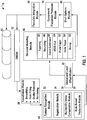
- FIG. 1 presents an overview of the system 10.
- the present system 10 identifies characteristic features of the ear canal and defines rule based protocols for designing custom hearing aid for the patient.
- the flow begins with a work order for a hearing aid stored in a digital work order management system DWOM 12 (this system serves as an interface between modeling/detailing software and the business systems, defining the communications protocol) in which digitized 3D shell feature data is subjected to a tessellation module 20 that performs smoothing, hole filling, outlier removal, and rendering based on the shell model.
- DWOM 12 this system serves as an interface between modeling/detailing software and the business systems, defining the communications protocol
- digitized 3D shell feature data is subjected to a tessellation module 20 that performs smoothing, hole filling, outlier removal, and rendering based on the shell model.
- the shell is then subjected to an analysis procedure 30 that includes feature recognition 32, a registration of features 34, a buildability index computation (BIA) implementation 36 as well as rule-based protocol handling 38.
- Data is then provided to a global and local offset module 40 and the data is then subjected to binaural processing 42 to augmented detailing and modeling protocols, such as tapering 44, rounding 46, canal extension 48, and IROS cut 50.
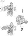
- Figure 14A illustrates a shell without an IROS cut
- Figure 14B illustrates a shell with an IROS cut.
- the IROS cut creates a step-like structure on the shell tip. This is used, e.g., to create an impression at the customer site in which the vent inlet on the tip side is bigger than it is in reality. This cut also provides certain audiological advantages.
- the augmented detailing protocols may further include the Prahl taper 52, helix taper 54, and scoop 56. A more detailed explanation of these procedures may be found in the pending patent application listed in the opening paragraph of
- a shell options module 60 allows the user to configure a number of parameters associated with the shell and store them.
- a faceplate integration module 80 is provided in order to assist in the proper placement of faceplates. Data from the completed design is the stored in a database 90 that includes the finalized shell information.
- the procedure defines the automatic protocols for automation of modeling, detailing and component placement of ITE shells, including the following categories described in more detail below: a) general rules; detailing rules for b) ITE, c) HS, d) CA, e) MC, f) CIC designs; g) rules for the receiver hole and vent; h) rules for component placement; and i) rules for collision detection.
- the software places components into the shell based on rules associated with device type.
- an insert module is placed such that the battery door is below the aperture line. All receivers are placed as close as possible to the canal tip, and the shell height can be reduced based on where a collision occurs between the electronic components associated with the faceplate, receiver suspension, and floating hybrid components.
- the placements of components is based on recognized device features and business logic.
- identified landmarks on the shell indicate the preliminary height of the device.
- the impression is oriented so that the helix, concha, and canal openings are at a consistent height and parallel to the base of the impression-a plane is defined through the base of the impression.
- the plane cuts the impression approximately 2mm down from the center of the flares of the tragus, anti-tragus, and helix towards the base of the impression.
- the system software has the ability to dynamically load and execute device based rules. Routines for modeling device types can be loaded as part of an Instrument Model Options in DWOM, and the software can display the device type being modeled using DWOM protocols.
- the system software can dynamically place electronic components based on assigned rules for the device type.
- the initial receiver placement is below the aperture and above the canal tips, and the location of the receiver in each device type is configurable.
- the faceplate placement and orientation are configurable per device type, and the placement takes into account unique device features.
- the faceplate orientation per device and the maximum allowable shell height are configurable as well.
- the software is able to place vent and receiver holes based on device types, and the faceplate placement and merge are based on pre-defined rules for the device type.
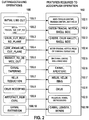
- Figure 2 shows the cutting-detailing operations 100 and the corresponding features 102 required to accomplish an appertaining cutting-detailing operation 100.
- the initial line cut 100.1 requires information pertaining to the anti-tragus center, tragus center, and anti helix 102.1.
- the intertragal nix cut round 100.2 requires information pertaining to the intertragal notch and the shell side 102.2.
- the crus cut round plane 100.3 requires information related to the crus, curs valley, and shell side 102.3.
- the low angular cut plane 100.4 requires information related to the intertragal notch, and the peak of the concha curvature 102.4.
- the reduct to device cut 100.5 requires information about material above the hollowed end of the device 103.5.
- Canal tapering 100.6 requires information about the canal and the aperture.
- a tapering of canals 8mm or longer is performed on ST, HS, and CA models only (i.e., more than 8mm from the low of the aperture to the cut line on the canal).
- a tapering of canals shorter than 8mm (ST, HS, and CA, i.e., less than 8mm from the lower of the aperture to the cut line on the canal) makes use of an extended taper.
- the canal width after the taper is applied should be no more than approximately 2mm larger than the narrowest area of the aperture.
- the helix reduction 100.8 requires information about the helix and the helix ring.
- the crus scooping 100.8 requires information pertaining to the crus.
- the artifact removal 100.9 requires information about bulbous regions, voids, and depression 102.9.
- the canal extension 100.10 requires information about the canal length and bends 102.10.
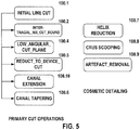
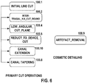
- the maximum allowed extension is 2mm. To achieve this, a plane is defined on the canal tip perpendicular to the direction of required extension, and the extension is performed, with a test to ensure that the canal does not extend at an incorrect angle based on the first and second bend areas. This list covers the primary cuts, but is in no way exhaustive as to the information that can be associated with other cuts as well.
- the system software inserts an initial cutting contour 310 (100.1) at the center of the tragus (not shown), the center of the anti-tragus (not shown), and the anti-helix 426.
- an initial cutting contour 310 100.1
- the transparent region is removed by this cut operation; this is a standard cut for all devices.
- the software automatically removes all material below the hollowed end of the shell 410, and recognizes and removes the lower end of the intertragal notch 440 (100.2), as illustrated by Figure 4 ; this is usually removed to reduce painful insertion for the patient.
- the degree of rounding of the intertragal notch can be configurable.
- the system software automatically trims the canal using the following criteria: the canal length is determined from the aperture to the canal tip, and the canal length is configurable for, e.g., "Small,” “Medium” (default) and “Large”.
- the software can taper the canal based on, e.g., "Long", “Medium”, and Short.
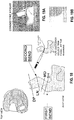
- Figure 18 illustrates an alternative for canal cutting, in which a canal length is specified either by market specific requirements or by a customer specified length.
- the cut can be made just after the first bend (SH), between the first and second bend (MD), at the second bend (LN), and after the second bend (DP). If a bell bore is selected, then in an embodiment, the canal is cut 2mm longer than the specified line cut.
- CIC models should generally always be cut 2-4mm past the second bend.
- the system should ensure a binaural match for: the canal length, the canal tip shape, and the canal cut plane (i.e., the resulting canal tip shape should be similar on both sides).
- the system software can automatically extend the canal according to the following criteria: the canal length is determined from the aperture to the canal tip, and may be configurable for, e.g., "Small”, “Medium” (default), and “Large”.
- the software can taper the canal based on, e.g., three configurable levels: “Long”, “Medium”, and “Short”. The tapering starts from the aperture and the optimum direction is normal to the centerline plane at the second bend.
- the software can determine whether a canal extension or tapering is required.
- the system software detects and reduces the helix length (100.7), which is configurable as, e.g., “Medium”, “Small”, and “Remove”.
- the software can provide two additional options or attributes to determine whether the helix should be preserved or not: "Preserve Helix” and "Remove Helix”. Faceplate lowering can be used to optimize and finalize the shell height. The requirements on rule based component placement are defined in subsequent sections.
- the system software can identify and remove the concha of the impression (Reduct_to_Device_Cut 100.5) by inserting a cutting plane 310 along the crus; the crus can be eliminated using a configured level of a Rounding-Crus_Cut_Round_Plane.
- the software can measure the distance from the center of the tragus to the concha.
- the minimum dimension for a half-shell measure from the tragus to the concha can be configurable as a shell width; all material beyond the shell width is preferably removed with a configured rounding
- a Low_Angular_Cut (100.4) can be inserted at a configurable angle (the "cut angle") from the inter-tragal notch to intersect a perpendicular line from the concha peak to the angular plane; the optimal shell height from the concha peak to the angle plane can be configurable as the concha height.
- the system software identifies all the features required to detail a canal (shown in Figure 2 ).
- the software recognizes and removes the concha of an impression by inserting the cutting plane along the crus using a configured level of rounding-the Crus_Cut_Round Plane 100.3, which is shown in Figure 7 .
- the software measures the distance from the center of the tragus to the mid-concha curvature.
- the minimum dimension for a canal is configurable as the shell width (specified in, e.g., mm); all material behind the shell width 442 is removed with a configurable level of rounding. If the measured distance is less than the shell width, the software can display an error message, such as, "Insufficient materials; specified device type cannot be built.”
- a Low_Angular_Cut 100.4 can be initiated at the inter-tragal notch and the concha curvature peak; the angular value can be configurable in the preferences table for each device type.
- the optimal shell height from the concha peak to the angle plane can be configurable as the concha height.
- Figure 8 illustrates the Low_Angular_Cuts_Plane 100.4 and the shell Reduce_to_Device_Cut 100.5.
- the system software identifies and removes the concha of the impression by inserting a cutting plane along the crus-the Crus_Cut_Round_Plane 100.3, with the level of rounding being configurable, as is illustrated in Figure 7 .
- the software measures the distance from the center of the tragus to the concha, and the minimum dimension for a mini-canal can be configurable as the shell width. All material behind the configured shell width 442 may be removed with a configured rounding.
- a Low_Angular_Cut 100.3 can be inserted at a configured angle (the cut angle) from the inter-tragal notch and the concha curvature peak.
- the optimal shell height from the concha peak to the angle plane can be configurable as the concha height.
- the faceplate is placed on the resulting impression from the rule based cuts; the faceplate is lowered until a collision occurs with the internal components or the shell, and the faceplate plane can be used to finalize the shell lowering.
- the receiver is placed close to the canal and below the aperture; the distance from the tip should be configurable as well. This is discussed in more detail below.
- the CIC requirements can be implemented using the following approaches: for the low angular cut plane 100.4, the aperture plane is oriented at a configured angle (cut angle) to the centerline direction; all material below the aperture is removed.
- the canal length from the aperture to the canal tip is configured as the shell height, and the canal is extended along the centerline by a configurable value (the canal extension 100.10). If the canal is longer than the configurable values, it is automatically trimmed and tapered by a configurable value (the canal tapering 100.6).
- a receiver is placed at a configured distance from the canal tip, and the faceplate is placed and lowered with collision verification of the electronics module with the shell and other components (discussed below).
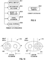
- Figure 10 illustrates a receiver hole 421 and vent configuration 416 on an elliptical canal tip.
- the software determines that, for CIC and ITE designs, the vent 416 and receiver channel 421 configurations are fixed as shown. In CIC and ITE designs, all vents follow a defined contour from the canal tip along the intertragal notch.
- the receiver hole 421 is drilled along the crus side of the canal, with the receiver 421 and vent channels 416 being equidistant from the sides of the impression canal and centered at the foci of the canal ellipse. (See Figure 10 (A-B)).
- the software determines that, for HS, CA, and MC designs, the vent 416 and receiver 421 channel configurations are interchanged (i.e., are the reverse of what is shown in Figure 10 ).
- the software determines that the receiver 421 and vent 416 configuration are the same as that for CIC and ITE designs. (See Figure 10 ).
- the shell wall thickness can have various configurable options.
- An option for a variable wall thickness is provided, for example, the system may provide for an adaptive wall thickness in high curvature regions.
- Variable thickness may be defined as a percent increase of the uniform wall thickness specification in a user configurable preferences database which may, e.g., be accessed via a displayed tab.
- Alternative variable thickness algorithms can be implemented with a polynomial function.
- the software can provide an option for specifying a uniform wall thickness (a default wall thickness).
- the software can provide an option for the application of selective wall thickness to a specified area of the shell-this region may be selectable by the user who may use, e.g., a lasso selection tool as is known in the graphical arts.
- a further capability of the software may be allowing empty areas of the shell to be filled with material.
- the software is designed to place the receiver hole on the correct side of the impression (left or right) using feature recognition (FR) protocols which identify different pre-defined areas of the shell such as helix, tragus, aperture etc. FR also can identify the canal and tip of the impression. By knowing the location of the tip of the impression, the software can automatically position the receiver hole on the left or on the right side of the tip, depending on the instructions for the specific shell type.
- FR feature recognition
- the software is designed to define vent location and orientation, and to allow control of the vent placement and the specification of the location of vents based on a particular device type.
- the software ensures the placement of vents based on whether an impression is identified as left and right ear impression.
- the software may provide an enable/disable function, via, e.g., check boxes of the user interface, in a user interface area associated with vent options (e.g., a vent tab under a preferences area), as well as in a user interface area in the "modeling" flow step for simulation vent placement.
- vent options e.g., a vent tab under a preferences area
- a virtual vent is shown to the user in the user interface.
- vent simulation considers the available space in the shell, and the vent generation takes into consideration the presence of components and possible interaction with components.
- a collision between vents and shell components may be highlighted-the software thus allows collision detection with components to take into account the presence of the vent.
- the user can change the vent type based on a prior database configuration, and modified vent types and options can be written to the database DB.
- the system allows the selection of both vent type and styles.
- vent wall thickness can be configurable for all device types, and the level of component penetration of electronic components into the vent wall is configurable as, e.g., a numerical value; this configuration parameter can be associated with the other vent configuration parameters and presented to the user under, e.g., the displayed vent tab.
- collision display for the colliding triangles can be configured in a different color (e.g., via a user display color tab).
- the software ensures that colliding components are placed at a configurable distance from nearest neighbors-this is essentially a self-correcting interference mechanism for collision. Colliding components within the shell shall have the ability to self-align to offset collision, and a feedback mechanism allows device size optimization .
- Electronic components can be lowered further into the shell as long as the resulting contact forces in a z-direction do not exceed a configurable maximum normal force value (see Figure 11 , illustrating reactional forces resulting from component interaction within the shell).
- the allowable maximum normal force can be configurable as a parameter MAX-Normal-Force in the user-configurable preferences.
- the software can automatically place the receiver at the canal tip, in accordance with the following criteria.
- the receiver snout is positioned from the canal tip on a configurable canal-receiver snout distance.
- the top of the receiver is placed such that its width is aligned to a major axis of the nearest shell ellipse.
- the center of the ellipse is at the center of the receiver geometry, and the receiver is placed below the aperture line.
- Double receivers are usually too large to fit into the canal, and thus, these are usually allowed to sit above the aperture.
- Collision detection is ideally enabled for all geometric component and new surfaces created, e.g. integrated faceplate surfaces, gluing surfaces, and suspensions.
- Figures 12A-F illustrate faceplate orientation according to different shell types.
- Figures 12A and 12B illustrate a full shell (FS) design.
- Figures 12C and 12D illustrate half shell (HS), canal (CA), and mini-canal (MC) designs.
- Figures 12E and 12F illustrate a completely-in-canal (CIC) design.
- Each of the figures illustrate the location of various features of the hearing aid shell 10 (note that reference characters are prime in Figures 12C and 12D , and double-prime in Figures 12E and 12F -use of the reference character without the corresponding prime marks is intended to be inclusive, where appropriate). Accordingly, the features of the helix 412, anti-tragus 414, vent 416, tragus 418, microphone 420, crus 422, and concha bowl 424 can be seen.
- the battery door ( Figure 13 ) is positioned such that it opens away from the tragus 418. But for HS, CA and MC designs, the battery door is positioned such that it opens towards the tragus 418. In the CIC design, the battery door is positioned so that it opens away from the vent hole 416.
- the software is designed to ensure that collision detection is facilitated between the merge surfaces and the components according to the following algorithm:
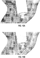
- FIGs 15A , B illustrate the shell which is clipped by the clipping plane to see the inside of the shell.
- the receiver collides with the shell, and the receiver may, e.g., be shown in red and the area where collision happens in yellow.
- faceplate may, e.g., be drawn in green. This permits rapid feedback to the user of the system.
- the software detects and may display all colliding triangles based on, e.g., a configurable color in a preferences table that can be modified by a user (or any other graphical tool that could serve to highlight a collision. This collision detection is enabled between:
- a user-interface element such as a check box
- all of the electrical components can have a configurable color to make them easy to visualize by the user.
- the present invention may be described in terms of functional block components and various processing steps. Such functional blocks may be realized by any number of hardware and/or software components configured to perform the specified functions.
- the present invention may employ various integrated circuit components, e.g., memory elements, processing elements, logic elements, look-up tables, and the like, which may carry out a variety of functions under the control of one or more microprocessors or other control devices.
- the elements of the present invention are implemented using software programming or software elements the invention may be implemented with any programming or scripting language such as C, C++, Java, assembler, or the like, with the various algorithms being implemented with any combination of data structures, objects, processes, routines or other programming elements.
- the present invention could employ any number of conventional techniques for electronics configuration, signal processing and/or control, data processing and the like.
Landscapes
- Engineering & Computer Science (AREA)
- Physics & Mathematics (AREA)
- Manufacturing & Machinery (AREA)
- Otolaryngology (AREA)
- Theoretical Computer Science (AREA)
- Health & Medical Sciences (AREA)
- General Health & Medical Sciences (AREA)
- Neurosurgery (AREA)
- Acoustics & Sound (AREA)
- Signal Processing (AREA)
- Geometry (AREA)
- General Engineering & Computer Science (AREA)
- General Physics & Mathematics (AREA)
- Evolutionary Computation (AREA)
- Computer Hardware Design (AREA)
- Processing Or Creating Images (AREA)
Claims (20)
- Verfahren zum Entwerfen und Herstellen einer Hörhilfe, das Folgendes umfasst:Empfangen (12) eines Arbeitsauftrags für eine Hörhilfe, die ein digitalisiertes 3D-Hüllenmodell enthält;Ausführen (20) eines Glättens und/oder Lochfüllens und/oder Ausreißerentfernens und/oder "Renderings" anhand des Hüllenmodells;Analysieren (32) des Hüllenmodells, um Merkmale zu erkennen und relevante Parameter zu bestimmen, die den Merkmalen zugeordnet sind;Registrieren und Speichern (34) in einem Datenspeicher der erkannten Merkmale und zugeordneten Parameter;Implementieren (38) einer auf Regeln beruhenden Protokollbearbeitung für das Hüllenmodell, die anhand eines gewählten Hüllentyps bestimmt ist;Ausführen (40) von globalen und lokalen Versetzungen an Daten, die dem Hüllenmodell zugeordnet sind;Ausführen (42) einer binauralen Verarbeitung an verbesserten Detaillierungs- und Modellierungsprotokollen, die an dem Hüllenmodell verwendet werden; undErzeugen einer Hörhilfe anhand des gemäß den vorhergehenden Schritten verarbeiteten Hüllenmodells.
- Verfahren nach Anspruch 1, wobei die verbesserten Detaillierungs- und Modellierungsprotokolle ein Abschrägen, ein Runden und eine Gangverlängerung enthalten.
- Verfahren nach Anspruch 1, wobei die auf Regeln beruhende Protokollbearbeitung eine Komponentenplatzierung bestimmt.
- Verfahren nach Anspruch 1, das ferner umfasst, eine Anzahl von Parametern zu konfigurieren, die der Hülle zugeordnet sind, und sie zu speichern.
- Verfahren nach Anspruch 1, das ferner umfasst, beim Platzieren von Komponenten zu helfen und zu gewährleisten, dass keine Kollisionen auftreten, die von dem Vorrichtungstyp abhängen.
- Verfahren nach Anspruch 1, das ferner umfasst, das Platzieren einer Gesichtsplatte auf der Hörhilfehülle zu unterstützen.
- Verfahren nach Anspruch 1, das ferner umfasst, einen Baubarkeitsindex für das Hüllenmodell zu bestimmen.
- Verfahren nach Anspruch 1, das ferner umfasst, automatisch Detaillierungsschnitte an dem Hüllenmodell auszuführen.
- Verfahren nach Anspruch 1, das ferner umfasst, Komponenten derart zu platzieren, dass zwischen den Komponenten ein minimaler zulässiger Abstand vorhanden ist.
- Verfahren nach Anspruch 1, das ferner umfasst, auf der Vorrichtung beruhende Regeln abhängig von einem Vorrichtungstyp dynamisch zu laden und auszuführen.
- Verfahren nach Anspruch 1, das ferner umfasst, elektronische Komponenten anhand von zugeteilten Regeln für den Vorrichtungstyp zu platzieren.
- Verfahren nach Anspruch 1, das ferner umfasst, eine Anwenderschnittstelle bereitzustellen, die manuelle kleinere Winkelanpassungen für primäre und kosmetische Schnitte erlaubt.
- Verfahren nach Anspruch 1, wobei das Verarbeiten ferner umfasst, einen Anfangslinienschnitt, einen intertragalen "Nix cut round", eine Crus-"Cut round"-Ebene, eine tiefe schräge Schnittebene, einen "Reduct to device"-Schnitt, ein Gangabschrägen, eine Helix-Verringerung, ein Crus-Ausschöpfen, eine Artefaktentfernung und eine Gangverlängerung auszuführen.
- Verfahren nach Anspruch 1, wobei für eine ohrinterne Vorrichtung (ITE-Vorrichtung) das Verarbeiten Folgendes umfasst:Einfügen eines Anfangsschnittumrisses an einem Mittelpunkt eines Tragus, einem Mittelpunkt eines Antitragus und einem Antihelix;Entfernen jeglichen Materials unter einem ausgehöhlten Ende der Hülle; undErkennen und Entfernen eines unteren Endes der intertragalen Kerbe.
- Verfahren nach Anspruch 14, das ferner Folgendes umfasst:Kategorisieren eines Attributs in mehrere Größenkategorien; undZuordnen eines Wertes zu der Attributgrößenkategorie; undVerwenden des zugeordneten Wertes beim Ausführen des Abschrägens, der Länge- und Rundungsvorgänge.
- Verfahren nach Anspruch 1, wobei für eine Halbschalenhörhilfevorrichtung (HS-Vorrichtung) das Verarbeiten umfasst, einen Anfangslinienschnitt, einen intertragalen "Nix cut round", eine tiefe schräge Schnittebene, einen "Reduct to device"-Schnitt, eine Gangverlängerung und ein Gangabschrägen auszuführen.
- Verfahren nach Anspruch 1, wobei für eine ganginterne Hörhilfevorrichtung (CA-Vorrichtung) das Verarbeiten Folgendes umfasst:Identifizieren aller Merkmale, die benötigt werden, um einen Gang zu detaillieren;Erkennen und Entfernen einer Ohrmuschel durch Einfügen einer Schnittebene entlang eines Crus unter Verwendung eines vorgegebenen konfigurierten Rundungsausmaßes;Ausführen eines tiefen schrägen Schnitts, der an einer intertragalen Kerbe und einem Ohrmuschelkrümmungsspitzenwert beginnt.
- Verfahren nach Anspruch 1, wobei für eine ganginterne Minihörhilfevorrichtung (MC-Vorrichtung) das Verarbeiten Folgendes umfasst:Identifizieren und Entfernen einer Ohrmuschel durch Einfügen einer Schnittebene entlang eines Crus mit einem vorgegebenen konfigurierbaren Rundungsausmaß;Entfernen jeglichen Materials hinter einer konfigurierten Hülle mit einem konfigurierten Runden;Einfügen eines tiefen schrägen Schnitts in einem vorgegebenen konfigurierten Winkel von einer intertragalen Kerbe und einem Ohrmuschelkrümmungsspitzenwert;Senken einer Gesichtsplatte bis gerade bevor eine Kollision mit internen Komponenten oder der Hülle auftritt; undPositionieren eines Empfängers in die Nähe eines Gangs und unter eine Öffnung in einem vordefinierten konfigurierbaren Abstand von einer Spitze des Gangs.
- Verfahren nach Anspruch 1, wobei für eine vollständig gehörganginterne Vorrichtung (CIC-Vorrichtung) das Verarbeiten Folgendes umfasst:Ausführen eines Anfangslinienschnitts, einer tiefen schrägen Schnittebene, eines "Reduct to device"-Schnitts, einer Gangverlängerung und eines Gangabschrägens, wobei für die tiefe schräge Schnittebene die Verarbeitung umfasst, eine Öffnungsebene in einem vorgegebenen konfigurierten Winkel zu einer Mittellinienrichtung auszurichten und alles Material unter der Öffnung zu entfernen, eine Ganglänge von der Öffnung zu einer Gangspitze als die Hüllenhöhe zu definieren und den Gang entlang einer Mittellinie um einen vorgegebenen konfigurierbaren Wert zu verlängern und einen Empfänger in einem vorgegebenen konfigurierbaren Abstand von der Gangspitze zu positionieren.
- Computerlesbare Medien, die Software-Algorithmen von computerlesbarem Code umfassen, die auf einem Prozessor ausgeführt werden können, wobei der Algorithmus Folgendes umfasst:einen Algorithmus zum Eingeben eines Arbeitsauftrags für eine Hörhilfe, der ein digitalisiertes 3D-Hüllenmodell mit Merkmaldaten enthält;einen Algorithmus zum Ausführen eines Glättens und/oder eines Lochfüllens und/oder eines Ausreißerentfernens und/oder eines "Renderings" anhand des Hüllenmodells;einen Algorithmus zum Analysieren des Hüllenmodells, um Merkmale zu erkennen und relevante Parameter, die den Merkmalen zugeordnet sind, zu bestimmen;einen Algorithmus zum Registrieren und Speichern in einem Datenspeicher der erkannten Merkmale und zugeordneten Parameter;einen Algorithmus zum Implementieren einer auf Regeln beruhenden Protokollbearbeitung für das Hüllenmodell, die anhand eines bestimmten Hüllentyps bestimmt ist;einen Algorithmus zum Ausführen von globalen und lokalen Versetzungen an Daten, die dem Hüllenmodel zugeordnet sind; undeinen Algorithmus zum Ausführen einer binauralen Verarbeitung an verbesserten Detaillierungs- und Modellierungsprotokollen, die an dem Hüllenmodell verwendet werden.
Applications Claiming Priority (1)
| Application Number | Priority Date | Filing Date | Title |
|---|---|---|---|
| US11/871,213 US20090097682A1 (en) | 2007-10-12 | 2007-10-12 | Computerized rule based binaural modeling system for the hearing aid design |
Publications (2)
| Publication Number | Publication Date |
|---|---|
| EP2048895A1 EP2048895A1 (de) | 2009-04-15 |
| EP2048895B1 true EP2048895B1 (de) | 2017-12-06 |
Family
ID=40260814
Family Applications (1)
| Application Number | Title | Priority Date | Filing Date |
|---|---|---|---|
| EP08166090.4A Not-in-force EP2048895B1 (de) | 2007-10-12 | 2008-10-08 | Computergestütztes regelbasiertes binaurales Formsystem und Verfahren für Hörgeräte |
Country Status (3)
| Country | Link |
|---|---|
| US (1) | US20090097682A1 (de) |
| EP (1) | EP2048895B1 (de) |
| DK (1) | DK2048895T3 (de) |
Families Citing this family (4)
| Publication number | Priority date | Publication date | Assignee | Title |
|---|---|---|---|---|
| US8150542B2 (en) * | 2006-06-14 | 2012-04-03 | Phonak Ag | Positioning and orienting a unit of a hearing device relative to individual's head |
| US8065118B2 (en) * | 2007-10-16 | 2011-11-22 | Siemens Hearing Instruments Inc. | Method for anatomically aware automatic faceplate placement for hearing instrument design |
| US8554352B2 (en) * | 2009-05-07 | 2013-10-08 | Siemens Hearing Instruments, Inc. | Method of generating an optimized venting channel in a hearing instrument |
| US8494814B2 (en) | 2009-11-02 | 2013-07-23 | Siemens Corporation | Methods for inlet and outlet modelling of vent as large as possible for hearing aid devices |
Family Cites Families (10)
| Publication number | Priority date | Publication date | Assignee | Title |
|---|---|---|---|---|
| US7050876B1 (en) * | 2000-10-06 | 2006-05-23 | Phonak Ltd. | Manufacturing methods and systems for rapid production of hearing-aid shells |
| US7092899B2 (en) * | 2000-10-31 | 2006-08-15 | Interlego Ag | Method and system for generating a brick model |
| ES2378060T3 (es) * | 2001-03-02 | 2012-04-04 | 3Shape A/S | Procedimiento para modelar piezas auriculares personalizadas |
| EP1246506A1 (de) * | 2001-03-26 | 2002-10-02 | Widex A/S | CAD-CAM-System zum Entwurf eines Hörgerätes |
| US20020196954A1 (en) * | 2001-06-22 | 2002-12-26 | Marxen Christopher J. | Modeling and fabrication of three-dimensional irregular surfaces for hearing instruments |
| EP1574111B1 (de) * | 2002-12-19 | 2017-06-14 | Siemens Corporation | Interaktive binaurale gehäuse-modellierung für hörgeräte |
| US7555356B2 (en) * | 2003-04-03 | 2009-06-30 | Phonak Ag | Method for manufacturing a body-worn electronic device adapted to the shape of an individual's body area |
| WO2006103236A1 (en) | 2005-03-29 | 2006-10-05 | Siemens Audiologische Technik Gmbh | Hearing aid impression buildability index computation tool |
| US8150542B2 (en) * | 2006-06-14 | 2012-04-03 | Phonak Ag | Positioning and orienting a unit of a hearing device relative to individual's head |
| US7605812B2 (en) | 2006-12-19 | 2009-10-20 | Siemens Aktiengesellschaft | Intelligent modeling method and system for earmold shell and hearing aid design |
-
2007
- 2007-10-12 US US11/871,213 patent/US20090097682A1/en not_active Abandoned
-
2008
- 2008-10-08 DK DK08166090.4T patent/DK2048895T3/en active
- 2008-10-08 EP EP08166090.4A patent/EP2048895B1/de not_active Not-in-force
Also Published As
| Publication number | Publication date |
|---|---|
| DK2048895T3 (en) | 2018-03-12 |
| EP2048895A1 (de) | 2009-04-15 |
| US20090097682A1 (en) | 2009-04-16 |
Similar Documents
| Publication | Publication Date | Title |
|---|---|---|
| EP1858293B1 (de) | System mit einem automatisierten Werkzeug und dazugehöriges Verfahren zur Entwicklung von Hörhilfen | |
| US20020196954A1 (en) | Modeling and fabrication of three-dimensional irregular surfaces for hearing instruments | |
| US10327080B2 (en) | Method of manufacturing hearing devices | |
| EP2107832B1 (de) | Verfahren zur adaptiven Konstruktion eines kleinen CIC-Hörinstrumentents | |
| EP1356709B1 (de) | Herstellungsverfahren und system zur schnellen erzeugung von hörhilfegerätschale | |
| EP2986029A1 (de) | Verfahren und System zur Modellierung einer maßgefertigten Otoplastik | |
| US7801708B2 (en) | Method and apparatus for the rigid and non-rigid registration of 3D shapes | |
| US20070201713A1 (en) | Method and Apparatus for Aperture Detection of 3D Hearing Aid Shells | |
| DK2048895T3 (en) | Computer-controlled rule-based binaural molding system and method for hearing aid design | |
| WO2002078233A3 (en) | Method for the production of a hearing aid housing and a hearing aid | |
| WO2002080617A3 (en) | Computer aided system for designing a hearing aid housing | |
| US8065118B2 (en) | Method for anatomically aware automatic faceplate placement for hearing instrument design | |
| EP2249585B1 (de) | Verfahren zur Erzeugung eines optimierten Belüftungskanals in einem Hörinstrument | |
| US8086427B2 (en) | Method and apparatus for the registration of 3D ear impression models | |
| EP1875775B1 (de) | Verfahren und system zum entwerfen einer hörgerätschale | |
| US8096383B2 (en) | Tapered vent for a hearing instrument | |
| EP4161101B1 (de) | Sensormontage in einer individuell angepassten hörgerätschale | |
| US8005652B2 (en) | Method and apparatus for surface partitioning using geodesic distance | |
| EP1980965B1 (de) | Computergestütztes automatisches Wachsschutzdesignformsystem und Verfahren für Hörgeräte | |
| EP2023662A1 (de) | System mit einem automatisierten Werkzeug und dazugehöriges Verfahren zur Entwicklung von Hörhilfen | |
| US20250278527A1 (en) | Systems and Methods for Designing Customized Hearing Devices for Users | |
| CN110326304A (zh) | 制造听力装置壳体的方法、听力装置壳体的预制件、听力装置壳体和听力装置 | |
| US20230065068A1 (en) | Cable alignment features in a custom-fitted hearing device shell | |
| EP4002883A1 (de) | Automatische positionsbestimmung für das gehäuse eines hörgerätes | |
| EP1762977A2 (de) | Verfahren und Vorrichtung zur Registrierung von 3D-Modellen von Ohrabdrücken |
Legal Events
| Date | Code | Title | Description |
|---|---|---|---|
| PUAI | Public reference made under article 153(3) epc to a published international application that has entered the european phase |
Free format text: ORIGINAL CODE: 0009012 |
|
| AK | Designated contracting states |
Kind code of ref document: A1 Designated state(s): AT BE BG CH CY CZ DE DK EE ES FI FR GB GR HR HU IE IS IT LI LT LU LV MC MT NL NO PL PT RO SE SI SK TR |
|
| AX | Request for extension of the european patent |
Extension state: AL BA MK RS |
|
| 17P | Request for examination filed |
Effective date: 20090914 |
|
| 17Q | First examination report despatched |
Effective date: 20091006 |
|
| AKX | Designation fees paid |
Designated state(s): AT BE BG CH CY CZ DE DK EE ES FI FR GB GR HR HU IE IS IT LI LT LU LV MC MT NL NO PL PT RO SE SI SK TR |
|
| RAP1 | Party data changed (applicant data changed or rights of an application transferred) |
Owner name: SIVANTOS, INC. |
|
| RIC1 | Information provided on ipc code assigned before grant |
Ipc: G06F 17/50 20060101ALI20170516BHEP Ipc: H04R 25/00 20060101AFI20170516BHEP |
|
| GRAP | Despatch of communication of intention to grant a patent |
Free format text: ORIGINAL CODE: EPIDOSNIGR1 |
|
| INTG | Intention to grant announced |
Effective date: 20170718 |
|
| GRAS | Grant fee paid |
Free format text: ORIGINAL CODE: EPIDOSNIGR3 |
|
| GRAA | (expected) grant |
Free format text: ORIGINAL CODE: 0009210 |
|
| AK | Designated contracting states |
Kind code of ref document: B1 Designated state(s): AT BE BG CH CY CZ DE DK EE ES FI FR GB GR HR HU IE IS IT LI LT LU LV MC MT NL NO PL PT RO SE SI SK TR |
|
| REG | Reference to a national code |
Ref country code: GB Ref legal event code: FG4D |
|
| REG | Reference to a national code |
Ref country code: AT Ref legal event code: REF Ref document number: 953381 Country of ref document: AT Kind code of ref document: T Effective date: 20171215 Ref country code: CH Ref legal event code: EP |
|
| REG | Reference to a national code |
Ref country code: IE Ref legal event code: FG4D |
|
| REG | Reference to a national code |
Ref country code: DE Ref legal event code: R096 Ref document number: 602008053232 Country of ref document: DE |
|
| REG | Reference to a national code |
Ref country code: CH Ref legal event code: NV Representative=s name: E. BLUM AND CO. AG PATENT- UND MARKENANWAELTE , CH |
|
| REG | Reference to a national code |
Ref country code: DK Ref legal event code: T3 Effective date: 20180308 |
|
| REG | Reference to a national code |
Ref country code: NL Ref legal event code: MP Effective date: 20171206 |
|
| REG | Reference to a national code |
Ref country code: LT Ref legal event code: MG4D |
|
| PG25 | Lapsed in a contracting state [announced via postgrant information from national office to epo] |
Ref country code: SE Free format text: LAPSE BECAUSE OF FAILURE TO SUBMIT A TRANSLATION OF THE DESCRIPTION OR TO PAY THE FEE WITHIN THE PRESCRIBED TIME-LIMIT Effective date: 20171206 Ref country code: FI Free format text: LAPSE BECAUSE OF FAILURE TO SUBMIT A TRANSLATION OF THE DESCRIPTION OR TO PAY THE FEE WITHIN THE PRESCRIBED TIME-LIMIT Effective date: 20171206 Ref country code: NO Free format text: LAPSE BECAUSE OF FAILURE TO SUBMIT A TRANSLATION OF THE DESCRIPTION OR TO PAY THE FEE WITHIN THE PRESCRIBED TIME-LIMIT Effective date: 20180306 Ref country code: LT Free format text: LAPSE BECAUSE OF FAILURE TO SUBMIT A TRANSLATION OF THE DESCRIPTION OR TO PAY THE FEE WITHIN THE PRESCRIBED TIME-LIMIT Effective date: 20171206 Ref country code: ES Free format text: LAPSE BECAUSE OF FAILURE TO SUBMIT A TRANSLATION OF THE DESCRIPTION OR TO PAY THE FEE WITHIN THE PRESCRIBED TIME-LIMIT Effective date: 20171206 |
|
| REG | Reference to a national code |
Ref country code: AT Ref legal event code: MK05 Ref document number: 953381 Country of ref document: AT Kind code of ref document: T Effective date: 20171206 |
|
| PG25 | Lapsed in a contracting state [announced via postgrant information from national office to epo] |
Ref country code: HR Free format text: LAPSE BECAUSE OF FAILURE TO SUBMIT A TRANSLATION OF THE DESCRIPTION OR TO PAY THE FEE WITHIN THE PRESCRIBED TIME-LIMIT Effective date: 20171206 Ref country code: BG Free format text: LAPSE BECAUSE OF FAILURE TO SUBMIT A TRANSLATION OF THE DESCRIPTION OR TO PAY THE FEE WITHIN THE PRESCRIBED TIME-LIMIT Effective date: 20180306 Ref country code: GR Free format text: LAPSE BECAUSE OF FAILURE TO SUBMIT A TRANSLATION OF THE DESCRIPTION OR TO PAY THE FEE WITHIN THE PRESCRIBED TIME-LIMIT Effective date: 20180307 Ref country code: LV Free format text: LAPSE BECAUSE OF FAILURE TO SUBMIT A TRANSLATION OF THE DESCRIPTION OR TO PAY THE FEE WITHIN THE PRESCRIBED TIME-LIMIT Effective date: 20171206 |
|
| PG25 | Lapsed in a contracting state [announced via postgrant information from national office to epo] |
Ref country code: NL Free format text: LAPSE BECAUSE OF FAILURE TO SUBMIT A TRANSLATION OF THE DESCRIPTION OR TO PAY THE FEE WITHIN THE PRESCRIBED TIME-LIMIT Effective date: 20171206 |
|
| PG25 | Lapsed in a contracting state [announced via postgrant information from national office to epo] |
Ref country code: SK Free format text: LAPSE BECAUSE OF FAILURE TO SUBMIT A TRANSLATION OF THE DESCRIPTION OR TO PAY THE FEE WITHIN THE PRESCRIBED TIME-LIMIT Effective date: 20171206 Ref country code: CZ Free format text: LAPSE BECAUSE OF FAILURE TO SUBMIT A TRANSLATION OF THE DESCRIPTION OR TO PAY THE FEE WITHIN THE PRESCRIBED TIME-LIMIT Effective date: 20171206 Ref country code: EE Free format text: LAPSE BECAUSE OF FAILURE TO SUBMIT A TRANSLATION OF THE DESCRIPTION OR TO PAY THE FEE WITHIN THE PRESCRIBED TIME-LIMIT Effective date: 20171206 |
|
| PG25 | Lapsed in a contracting state [announced via postgrant information from national office to epo] |
Ref country code: RO Free format text: LAPSE BECAUSE OF FAILURE TO SUBMIT A TRANSLATION OF THE DESCRIPTION OR TO PAY THE FEE WITHIN THE PRESCRIBED TIME-LIMIT Effective date: 20171206 Ref country code: PL Free format text: LAPSE BECAUSE OF FAILURE TO SUBMIT A TRANSLATION OF THE DESCRIPTION OR TO PAY THE FEE WITHIN THE PRESCRIBED TIME-LIMIT Effective date: 20171206 Ref country code: AT Free format text: LAPSE BECAUSE OF FAILURE TO SUBMIT A TRANSLATION OF THE DESCRIPTION OR TO PAY THE FEE WITHIN THE PRESCRIBED TIME-LIMIT Effective date: 20171206 Ref country code: IT Free format text: LAPSE BECAUSE OF FAILURE TO SUBMIT A TRANSLATION OF THE DESCRIPTION OR TO PAY THE FEE WITHIN THE PRESCRIBED TIME-LIMIT Effective date: 20171206 |
|
| REG | Reference to a national code |
Ref country code: DE Ref legal event code: R097 Ref document number: 602008053232 Country of ref document: DE |
|
| PLBE | No opposition filed within time limit |
Free format text: ORIGINAL CODE: 0009261 |
|
| STAA | Information on the status of an ep patent application or granted ep patent |
Free format text: STATUS: NO OPPOSITION FILED WITHIN TIME LIMIT |
|
| REG | Reference to a national code |
Ref country code: FR Ref legal event code: PLFP Year of fee payment: 11 |
|
| 26N | No opposition filed |
Effective date: 20180907 |
|
| PG25 | Lapsed in a contracting state [announced via postgrant information from national office to epo] |
Ref country code: SI Free format text: LAPSE BECAUSE OF FAILURE TO SUBMIT A TRANSLATION OF THE DESCRIPTION OR TO PAY THE FEE WITHIN THE PRESCRIBED TIME-LIMIT Effective date: 20171206 |
|
| REG | Reference to a national code |
Ref country code: BE Ref legal event code: MM Effective date: 20181031 |
|
| PG25 | Lapsed in a contracting state [announced via postgrant information from national office to epo] |
Ref country code: MC Free format text: LAPSE BECAUSE OF FAILURE TO SUBMIT A TRANSLATION OF THE DESCRIPTION OR TO PAY THE FEE WITHIN THE PRESCRIBED TIME-LIMIT Effective date: 20171206 Ref country code: LU Free format text: LAPSE BECAUSE OF NON-PAYMENT OF DUE FEES Effective date: 20181008 |
|
| REG | Reference to a national code |
Ref country code: IE Ref legal event code: MM4A |
|
| PG25 | Lapsed in a contracting state [announced via postgrant information from national office to epo] |
Ref country code: BE Free format text: LAPSE BECAUSE OF NON-PAYMENT OF DUE FEES Effective date: 20181031 |
|
| PG25 | Lapsed in a contracting state [announced via postgrant information from national office to epo] |
Ref country code: IE Free format text: LAPSE BECAUSE OF NON-PAYMENT OF DUE FEES Effective date: 20181008 |
|
| PG25 | Lapsed in a contracting state [announced via postgrant information from national office to epo] |
Ref country code: MT Free format text: LAPSE BECAUSE OF NON-PAYMENT OF DUE FEES Effective date: 20181008 |
|
| PGFP | Annual fee paid to national office [announced via postgrant information from national office to epo] |
Ref country code: DE Payment date: 20191023 Year of fee payment: 12 |
|
| PGFP | Annual fee paid to national office [announced via postgrant information from national office to epo] |
Ref country code: DK Payment date: 20191022 Year of fee payment: 12 Ref country code: FR Payment date: 20191022 Year of fee payment: 12 |
|
| PG25 | Lapsed in a contracting state [announced via postgrant information from national office to epo] |
Ref country code: TR Free format text: LAPSE BECAUSE OF FAILURE TO SUBMIT A TRANSLATION OF THE DESCRIPTION OR TO PAY THE FEE WITHIN THE PRESCRIBED TIME-LIMIT Effective date: 20171206 |
|
| PGFP | Annual fee paid to national office [announced via postgrant information from national office to epo] |
Ref country code: CH Payment date: 20191023 Year of fee payment: 12 |
|
| PGFP | Annual fee paid to national office [announced via postgrant information from national office to epo] |
Ref country code: GB Payment date: 20191023 Year of fee payment: 12 |
|
| PG25 | Lapsed in a contracting state [announced via postgrant information from national office to epo] |
Ref country code: PT Free format text: LAPSE BECAUSE OF FAILURE TO SUBMIT A TRANSLATION OF THE DESCRIPTION OR TO PAY THE FEE WITHIN THE PRESCRIBED TIME-LIMIT Effective date: 20171206 |
|
| PG25 | Lapsed in a contracting state [announced via postgrant information from national office to epo] |
Ref country code: CY Free format text: LAPSE BECAUSE OF FAILURE TO SUBMIT A TRANSLATION OF THE DESCRIPTION OR TO PAY THE FEE WITHIN THE PRESCRIBED TIME-LIMIT Effective date: 20171206 Ref country code: HU Free format text: LAPSE BECAUSE OF FAILURE TO SUBMIT A TRANSLATION OF THE DESCRIPTION OR TO PAY THE FEE WITHIN THE PRESCRIBED TIME-LIMIT; INVALID AB INITIO Effective date: 20081008 |
|
| PG25 | Lapsed in a contracting state [announced via postgrant information from national office to epo] |
Ref country code: IS Free format text: LAPSE BECAUSE OF FAILURE TO SUBMIT A TRANSLATION OF THE DESCRIPTION OR TO PAY THE FEE WITHIN THE PRESCRIBED TIME-LIMIT Effective date: 20180406 |
|
| REG | Reference to a national code |
Ref country code: DE Ref legal event code: R119 Ref document number: 602008053232 Country of ref document: DE |
|
| REG | Reference to a national code |
Ref country code: DK Ref legal event code: EBP Effective date: 20201031 |
|
| REG | Reference to a national code |
Ref country code: CH Ref legal event code: PL |
|
| GBPC | Gb: european patent ceased through non-payment of renewal fee |
Effective date: 20201008 |
|
| PG25 | Lapsed in a contracting state [announced via postgrant information from national office to epo] |
Ref country code: FR Free format text: LAPSE BECAUSE OF NON-PAYMENT OF DUE FEES Effective date: 20201031 Ref country code: DE Free format text: LAPSE BECAUSE OF NON-PAYMENT OF DUE FEES Effective date: 20210501 |
|
| PG25 | Lapsed in a contracting state [announced via postgrant information from national office to epo] |
Ref country code: CH Free format text: LAPSE BECAUSE OF NON-PAYMENT OF DUE FEES Effective date: 20201031 Ref country code: GB Free format text: LAPSE BECAUSE OF NON-PAYMENT OF DUE FEES Effective date: 20201008 Ref country code: LI Free format text: LAPSE BECAUSE OF NON-PAYMENT OF DUE FEES Effective date: 20201031 |
|
| PG25 | Lapsed in a contracting state [announced via postgrant information from national office to epo] |
Ref country code: DK Free format text: LAPSE BECAUSE OF NON-PAYMENT OF DUE FEES Effective date: 20201031 |