EP2048596A1 - Device and method for recording images of objects moved on a supply device - Google Patents
Device and method for recording images of objects moved on a supply device Download PDFInfo
- Publication number
- EP2048596A1 EP2048596A1 EP08105234A EP08105234A EP2048596A1 EP 2048596 A1 EP2048596 A1 EP 2048596A1 EP 08105234 A EP08105234 A EP 08105234A EP 08105234 A EP08105234 A EP 08105234A EP 2048596 A1 EP2048596 A1 EP 2048596A1
- Authority
- EP
- European Patent Office
- Prior art keywords
- speed
- conveyor
- acceleration
- line
- line sensor
- Prior art date
- Legal status (The legal status is an assumption and is not a legal conclusion. Google has not performed a legal analysis and makes no representation as to the accuracy of the status listed.)
- Granted
Links
Images


Classifications
-
- G—PHYSICS
- G06—COMPUTING; CALCULATING OR COUNTING
- G06K—GRAPHICAL DATA READING; PRESENTATION OF DATA; RECORD CARRIERS; HANDLING RECORD CARRIERS
- G06K7/00—Methods or arrangements for sensing record carriers, e.g. for reading patterns
- G06K7/10—Methods or arrangements for sensing record carriers, e.g. for reading patterns by electromagnetic radiation, e.g. optical sensing; by corpuscular radiation
- G06K7/10544—Methods or arrangements for sensing record carriers, e.g. for reading patterns by electromagnetic radiation, e.g. optical sensing; by corpuscular radiation by scanning of the records by radiation in the optical part of the electromagnetic spectrum
- G06K7/10712—Fixed beam scanning
- G06K7/10722—Photodetector array or CCD scanning
-
- B—PERFORMING OPERATIONS; TRANSPORTING
- B07—SEPARATING SOLIDS FROM SOLIDS; SORTING
- B07C—POSTAL SORTING; SORTING INDIVIDUAL ARTICLES, OR BULK MATERIAL FIT TO BE SORTED PIECE-MEAL, e.g. BY PICKING
- B07C3/00—Sorting according to destination
- B07C3/10—Apparatus characterised by the means used for detection ofthe destination
- B07C3/14—Apparatus characterised by the means used for detection ofthe destination using light-responsive detecting means
-
- G—PHYSICS
- G06—COMPUTING; CALCULATING OR COUNTING
- G06K—GRAPHICAL DATA READING; PRESENTATION OF DATA; RECORD CARRIERS; HANDLING RECORD CARRIERS
- G06K7/00—Methods or arrangements for sensing record carriers, e.g. for reading patterns
- G06K7/10—Methods or arrangements for sensing record carriers, e.g. for reading patterns by electromagnetic radiation, e.g. optical sensing; by corpuscular radiation
- G06K7/10544—Methods or arrangements for sensing record carriers, e.g. for reading patterns by electromagnetic radiation, e.g. optical sensing; by corpuscular radiation by scanning of the records by radiation in the optical part of the electromagnetic spectrum
- G06K7/10792—Special measures in relation to the object to be scanned
Definitions
- the invention relates to a device for taking pictures of objects moved on a conveyor according to the preamble of claim 1 and a corresponding method according to the preamble of claim 13.
- objects are coded, which are read by a code reader.
- a common practical application are barcodes with corresponding barcode scanners.
- other codes are used for identification, such as two-dimensional codes such as a Maxicode or an Aztec code, or labels that are decoded with an OCR.
- images of the objects with the codes are recorded.
- the objects are conveyed past the code reader and image data of the objects with the codes arranged thereon are obtained by line-by-line scanning.
- the conveyor on which the objects are moved does not always move at a steady speed. This is especially the case with tray sorters, where in each case one shell of the conveyor receives only one object.
- objects are transported by means of so-called bullet on the shells. If no shell is currently free, the bullet must be delayed or stopped.
- a code reader mounted over the bullet tape which scans objects line by line then only provides distorted images because the relative movement of the object to the code reader is irregular. This problem occurs not only with bullet ribbons, but with any change in the speed of the conveyor on which the objects are located. Distortions in the However, recorded image data complicate the decoding, especially when conventional text recognition programs are to evaluate the images to decode a label such as an address.
- the invention is based on the principle of detecting disturbances in the smooth movement of the conveyor and to respond to it.
- the density of the recorded image lines no longer depends on the speed of the conveyor, but ultimately on the conveyed distance of the objects, which represents the right measure for a distortion-free and uniformly resolved image. Therefore, the speed determination device can also be understood as indicating the distance traveled without immediate reference to time. However, since a temporal reference is established via the recording frequency, ultimately a speed measure is also used in this case.
- the evaluation unit is preferably designed to adapt the recording frequency adaptively such that the line sensor records image data of equidistant lines of the object.
- the reference is the object on its conveying speed
- the image lines are so in this way equidistant and thus evenly distributed over the object, and this means a uniform image resolution in the direction transverse to the lines, which corresponds to an image that in a fictitious situation with uniform conveying speed and constant recording frequency has been recorded.
- the evaluation is thus independent of disturbances due to fluctuations in the conveying speed.
- the line sensor is designed to be set to a basic recording frequency with associated recording parameters, which corresponds in particular to a maximum conveying speed of the conveyor, and the evaluation unit is adapted to adapt the recording frequency and / or the recording parameters to one compared to the maximum Conveyor speed changed speed of motion to specify the line sensor differentially.
- recording parameters may be brightness, gain factors, exposure times or the like.
- the system is thus set to a basic setting that corresponds to the normal state of the conveyor running smoothly. In this basic state according to the invention must not be intervened. Only when a different from the ground state conveyor speed is detected, an adjustment of the frequency is made and possibly also one or each dependent on the frequency recording parameters modified, such as the shutter speed shortened to accommodate a higher recording frequency, and accordingly increases the gain.
- the speed determination device is a displacement sensor, an incremental encoder or another sensor upstream of the line sensor.
- a sensor is often integrated into the conveyor anyway to know the speed for reasons independent of code reading. If the line sensor knows the speed in time, the adjustment of the recording frequency can be planned in advance and then executed.
- a displacement sensor indicates how big the conveyor of the object since the last shot. This information can be used to determine when to record the next line and is therefore a measure of the appropriate recording frequency.
- the speed determination device is a conveyor control of the conveyor, which specifies in particular the speed profile of the conveyor, and the conveyor control can transmit data on the speed profile to the evaluation unit, in particular a current speed, a duration of a subsequent acceleration phase, a start of the acceleration phase and / or a Final velocity after completion of the acceleration phase included.
- acceleration in the physical sense is to be understood, ie includes a deceleration or deceleration at negative acceleration.
- an acceleration phase at constant acceleration with output speed, end speed, start and duration of the acceleration phase is overdetermined, so it is sufficient to transfer only a part of these parameters. If data about a phase of non-uniform movement of the conveyor is transferred directly from the conveyor control, On the one hand, an actual measurement of the speed can be dispensed with, on the other hand, data on the speed change are available well in advance.
- the conveyor is preferably a tray conveyor or its bullet conveyor.
- a tray conveyor can easily arise the problem of an already occupied shell and therefore required speed adjustment. Therefore, the invention is particularly suitable for tray conveyors, because they can compensate for distortions of the image data by the periodic acceleration phases occurring here.
- the time-varying recording frequency for a given velocity profile of an object is stored in the evaluation unit as temporal intervals between every two recordings in a table, the entries in the table describing a hyperbola in particular.
- the device can thus be prepared in advance for specific speed changes of the conveyor.
- the table can be calculated in a preliminary phase, but also online, at startup or during a maintenance break, entered or read in via an interface or a mains connection.
- the hyperbola as a table of values stored in the table is particularly advantageous because it is the most suitable for taking a uniformly resolved image because of the inversely proportional relationship between recording frequency and period, ie the time between two recordings, and the proportional relationship between recording frequency and conveying speed Function for the treatment of a phase with uniform acceleration.
- the evaluation unit is designed so that entries in the table are predefined, in particular by inputting, reading, or by means of a predefined speed profile, in particular as hyperbolas from a maximum conveying speed, a delayed conveying speed, and a uniform acceleration phase between, indicated by start time, end time and / or acceleration.
- a predefined speed profile in particular as hyperbolas from a maximum conveying speed, a delayed conveying speed, and a uniform acceleration phase between, indicated by start time, end time and / or acceleration.
- the invention of the acceleration phase descriptive data independently generate the table and thus facilitate the setup.
- the evaluation unit is designed to use a table value multiple times to map longer acceleration phases, and / or to cause a recording stop of the line sensor when the movement speed is zero, so the conveyor is stopped.
- the table for saving memory and computational effort can be more roughly resolved by using each value multiple times.
- the apparatus is capable of responding adequately to a tape stop where further recording of image data can not provide useful information. When restarting the band, a smooth transition can be ensured, because this is nothing more than an acceleration phase with initial velocity zero, which according to the invention can be absorbed like any other acceleration phase.
- a further table is provided in the evaluation unit, which contains temporal intervals for the recording frequency in the event that the sign changes in an acceleration phase, ie an acceleration reversal takes place in order to ensure a smooth transition of the time intervals.
- the recording frequency plotted against time could have a kink which is reflected in the image data as spurious distortion.
- the evaluation unit is at least partially implemented on a programmable logic module, in particular an FPGA, of the line sensor, wherein the line sensor has at least one input, with which the logic module can be instructed to start and carry out the adjustment of the recording frequency over a predetermined speed profile.
- the invention is thus essentially encapsulated implemented on a separate block, which can be caused by a simple start command to compensate for disturbing influences by speed changes of the conveyor. This enables a simple, cost-effective and modular integration of the solution according to the invention into existing reading systems.
- an already existing logic module can be equipped with the functionality according to the invention.
- FIG. 1 shows in a schematic three-dimensional representation of the arrangement of an embodiment of a line sensor 10 according to the invention over a conveyor belt 12 on which objects 14 in a direction indicated by the arrows 16 direction of the sensor 10 are moved past.
- the objects 14 carry information 20, which are detected and read by the line sensor 10.
- the line sensor 10 has an only schematically illustrated lens 22 with an imaging optics and a line sensor 24, for example, a CMOS or CCD line.
- the line sensor 24 supplies image data of the objects 14 in a reading plane 18. These image data, which are recorded line by line with the movement of the objects 14 through the reading plane 18, are combined by a camera control 26 into an overall image in order to enable image evaluations.
- image evaluations is the decoding of the information 20, such as bar codes, two-dimensional codes or text recognition by the controller 26 or in a downstream, in FIG. 1 not shown system.
- another technical implementation may also be provided as a line sensor 10, for example scanning the line or any other known opto-electronic method.
- a message node 28 is connected to the controller 26, for example as part of a data network or as a bus system, which receives data via the conveyor belt 12 from a conveyor control 30 and forwards it to the controller 26.
- the conveyor control 30 is responsible for controlling the movement of the conveyor belt 12, that is, accelerating, decelerating, starting, stopping or maintaining it at a certain conveying speed.
- the controller 26 with the conveyor control 30 may also be provided to measure the speed or position of the conveyor belt 12 with its own sensor, which is upstream of the line scan camera 10 or integrated into this, such as an incremental encoder, a displacement sensor or an upstream optoelectronic sensor.
- the conveyor belt 12 is operated in normal operation at a constant maximum speed of 2m / s.
- the conveyor control 30 is able to lower the speed to 0.5 m / s and then bring it back to the maximum speed.
- the speed change occurs in a braking or acceleration phase of 500 ms at a constant acceleration of ⁇ 3 m / s 2 . This is particularly necessary when the conveyor belt 12 is a bullet conveyor for a Schalensorter, which must be braked when no shell is currently free.
- the invention is not limited to this particular speed profile of the conveyor 12, but capable of generating at any constant and non-constant speed undistorted image data by the recording frequency of the line sensor 10 to the current speed and thus connected to the between two shots of the Line sensor 10 adapted to move from the object 14 distance.
- the adaptation of the recording frequency will now be explained on the basis of a speed profile, as shown in FIG. 2 is shown.
- the actually relevant value is its reciprocal value, that is to say the recording period or the time which elapses between two recordings of the line sensor 10. This can be handled directly by the controller 26 by waiting after a recording, the respectively required recording period. Therefore, in FIG. 2 in addition to the dashed speed profiles shown with a solid line instead of the recording frequency whose reciprocal, namely the recording period T shown.
- the conveyor belt 12 initially moves at a maximum speed of 2 m / s, while the line sensor 10 scans the conveyed objects 14 line by line with a basic recording frequency shown in arbitrary units.
- the conveyor belt is decelerated at a constant acceleration of 3 m / s 2 within 500 ms to a retarded speed of 0.5 m / s.
- the recording period during the braking phase increases in a hyperbolic manner.
- the line sensor 10 picks up image data at an increased constant recording frequency per line.
- the conveyor belt 12 is uniformly accelerated again to its original maximum speed of 2 m / s (third and fourth dashed vertical line), wherein in the acceleration phase, the recording period is shortened hyperbolic analogous to the braking phase.
- the line sensor 10 is set with its recording parameters such as brightness or exposure time and also with the recording frequency to a ground state, which corresponds to the maximum speed of the conveyor 12. If the speed changes, then the pickup frequency is adjusted by adding to the pickup period of the ground state a differentiated fraction of the pickup frequency Adaptation corresponds. In the same way, the recording parameters are adapted to the changed recording period.
- the underlying maximum speed can be specified or adaptively determined during operation. For this determination, the speed data may be determined by the controller 26 itself or transmitted via the message node 28 from the conveyor control 30.
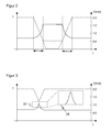
- FIG. 3 is one of the FIG. 2 Analog representation to illustrate a special situation in which is accelerated during braking again.
- the dotted section of the recording period plotted over time shows a kink at the point where the sign of acceleration reverses. This kink would lead to a distortion of the image data. Since the line sensor 10 is informed about the kink in advance via the conveyor control 30, as shown in the enlarged section 34, a smoothing of the recording period can be performed and thus the distortion can be avoided.
- a method for adjusting the recording frequency is shown, which is based on a table in which values for suitable recording periods are stored for a given velocity profile.
- the table is a look-up table for a hyperbola, for other speed profiles the table must be calculated from the inverse relationship between scan frequency and scan period and the relationship between conveyor 12 speed and the scan frequency, which is proportional to a desired uniform resolution of the image data become.
- Such a calculation can be made in advance and the table can be stored in a non-volatile memory, but the controller 26 may also be able to independently calculate the table from a velocity profile.
- Further configuration methods consist of inputting or reading in the value table via a network connection or an operator interface.
- a first step S1 in a phase in which the conveyor 12 moves at a maximum conveying speed, the line sensor 10 operates at a basic recording frequency.
- the line sensor 10 receives a message from the conveyor control 30, in which a modified speed profile is announced from a fixed time t0. In the illustrated example, this is a braking phase whose parameters the conveyor control 30 of the controller 26 of the line sensor 10 passes.
- a third step S3 which consists of a loop to be subdivided into sub-steps S3a-S3d, from the time point t0 the table is processed with the recording periods associated with the speed profile until the braking phase is over.
- one line is recorded per loop passage (S3a), the next recording period or waiting time is read from the table (S3b), the corresponding time is waited for (S3c) and it is checked whether the end of the table has been reached (S3d). If the end of the table has not yet been reached, the loop begins again with a recording of the next line (S3a).
- step S4 the loop is exited and checked in a further step S4 whether, according to the parameters passed in step S2, the braking phase has also ended, or whether the velocity is again constant after the current measurement. If this is the case, then further image data are generated line by line with a recording period which corresponds to the last table value and thus to a recording period which corresponds to the final speed achieved. If, on the other hand, the braking phase has not yet ended in step S4, it is checked (S6) whether the conveyor 12 has been stopped. If this is the case, further recordings are stopped until the conveyor 12 is approached again in a renewed acceleration phase. Otherwise, the brake phase is not yet completed, although no more values are provided in the table. Then, as in step S5, the last table value for the recording period is continued, because this may not be the ideal, but in any case the best, available value.
- the described pass through an acceleration phase may be a brake phase, a true acceleration phase with positive acceleration or a mixture of both with single or multiple motion reversal.
- the procedure is the same in each case because the required recording periods are available in the table. This also applies to the special case of acceleration from a standstill of the conveyor 12, which offers no special feature from the point of view of the method according to the invention.
- the implementation via a value table is only a particularly simple implementation, the invention is not limited thereto.
- the speed or the respective distances traveled by the conveyor 12 are determined dynamically by the line sensor 26 or an upstream sensor and from this the online or with a time offset, the next recording period is calculated.
- the controller 26 is entirely or only that part which the method according to the invention in particular according to FIG. 4 including the look-up table implemented on its own logic device, such as an FPGA. It is then sufficient to tell this logic module which velocity profile is present, and this returns the appropriate recording periods in chronological order.
- a whole series of tables, which correspond to different speed profiles, braking phases or acceleration phases, can be stored specifically in the FPGA.
- the invention can then be easily integrated into existing systems by instead of a constant waiting time between two recordings, the FPGA is caused by a simple switching command for the output of adapted recording periods, which are used as a waiting time.
Abstract
Description
Die Erfindung betrifft eine Vorrichtung zum Aufnehmen von Bildern von auf einer Fördereinrichtung bewegten Objekten nach dem Oberbegriff von Anspruch 1 und ein entsprechendes Verfahren nach dem Oberbegriff von Anspruch 13.The invention relates to a device for taking pictures of objects moved on a conveyor according to the preamble of claim 1 and a corresponding method according to the preamble of claim 13.
Für die Automatisierung von logistischen Anwendungen, beispielsweise das automatische Sortieren von Objekten, werden Objekte mit einem Code versehen, die von einem Codeleser ausgelesen werden. Eine häufige praktische Anwendung sind Barcodes mit entsprechenden Barcodescannern. Zur Identifizierung werden aber auch andere Kodierungen verwendet, etwa zweidimensionale Codes wie ein Maxicode oder ein Aztec-Code, oder Beschriftungen, die mit einer Texterkennung (OCR) dekodiert werden. Um solche Codes zu lesen, werden Bilder der Objekte mit den Codes aufgenommen.For the automation of logistical applications, for example the automatic sorting of objects, objects are coded, which are read by a code reader. A common practical application are barcodes with corresponding barcode scanners. However, other codes are used for identification, such as two-dimensional codes such as a Maxicode or an Aztec code, or labels that are decoded with an OCR. To read such codes, images of the objects with the codes are recorded.
In einer automatisiert arbeitenden Lesevorrichtung, etwa bei einer Gepäckabfertigung in Flughäfen oder der automatisierten Sortierung von Paketen in Logistikzentren, werden die Objekte an dem Codeleser vorbei gefördert und Bilddaten der Objekte mit den darauf angeordneten Codes durch zeilenweise Abtastung gewonnen.In an automated reading device, such as baggage handling in airports or the automated sorting of packages in logistics centers, the objects are conveyed past the code reader and image data of the objects with the codes arranged thereon are obtained by line-by-line scanning.
Die Fördereinrichtung, auf der die Objekte bewegt werden, bewegt sich nicht immer mit einer gleichmäßigen Geschwindigkeit. Dies ist besonders der Fall bei Schalensortern, wo jeweils eine Schale der Fördereinrichtung nur ein Objekt aufnimmt. Bei der Beladung eines solchen Schalensorters werden Objekte mittels so genannter Einschussbänder auf die Schalen transportiert. Wenn aktuell keine Schale frei ist, muss das Einschussband verzögert oder angehalten werden. Ein über dem Einschussband montierter Codeleser, der Objekte zeilenweise abtastet, liefert dann nur verzerrte Bilder, weil die relative Bewegung des Objekts zum Codeleser unregelmäßig ist. Dieses Problem tritt nicht nur an Einschussbändern auf, sondern bei jeglicher Geschwindigkeitsänderung des Förderers, auf dem sich die Objekte befinden. Verzerrungen in den aufgenommenen Bilddaten erschweren aber die Dekodierung, besonders wenn herkömmliche Texterkennungsprogramme die Bilder auswerten sollen, um eine Beschriftung wie eine Adresse zu dekodieren.The conveyor on which the objects are moved does not always move at a steady speed. This is especially the case with tray sorters, where in each case one shell of the conveyor receives only one object. When loading such a scarf sorters objects are transported by means of so-called bullet on the shells. If no shell is currently free, the bullet must be delayed or stopped. A code reader mounted over the bullet tape which scans objects line by line then only provides distorted images because the relative movement of the object to the code reader is irregular. This problem occurs not only with bullet ribbons, but with any change in the speed of the conveyor on which the objects are located. Distortions in the However, recorded image data complicate the decoding, especially when conventional text recognition programs are to evaluate the images to decode a label such as an address.
Es ist daher Aufgabe der Erfindung, einen Barcodescanner mit zeilenweiser Gewinnung von Bilddaten dahingehend weiterzubilden, dass er verzerrungsfreie oder weniger verzerrte Bilder liefert.It is therefore an object of the invention to develop a bar code scanner with line by line extraction of image data to the effect that it provides distortion-free or less distorted images.
Diese Aufgabe wird durch eine Vorrichtung und ein Verfahren zum Aufnehmen von Bildern nach Anspruch 1 beziehungsweise 13 gelöst. Indem die Aufnahmefrequenz des Zeilensensors an die Bewegungsgeschwindigkeit angepasst wird, kann die Auflösung der Bilddaten unabhängig von dem Bewegungsprofil bleiben. Nachgelagerte Bildauswertungen einschließlich der Dekodierung oder Texterkennungen können mit Bilddaten arbeiten, die von Störungen, Verzerrungen und sonstigen Artefakten durch eine unterschiedliche Fördergeschwindigkeit befreit sind. Dadurch wird die Auswertung vereinfacht, und vor allem werden Fehllesungen vermieden und damit die Leserate erhöht, so dass eine aufwändige und kostentreibende manuelle Nachbearbeitung der automatisierten Sortierung seltener erforderlich wird.This object is achieved by an apparatus and a method for taking pictures according to claims 1 and 13, respectively. By adjusting the pick-up frequency of the line sensor to the speed of movement, the resolution of the image data can remain independent of the motion profile. Downstream image analysis, including decoding or text recognition, can work with image data that is free of distortion, distortion, and other artifacts due to a different conveying speed. This simplifies the evaluation and, above all, avoids incorrect readings and thus increases the read rate, so that time-consuming and costly manual post-processing of the automated sorting is required less frequently.
Die Erfindung geht dabei von dem Prinzip aus, Störungen in dem gleichmäßigen Bewegungsablauf der Fördereinrichtung zu erkennen und darauf zu reagieren. Die Dichte der aufgenommenen Bildzeilen hängt dann nicht mehr von der Geschwindigkeit des Förderers ab, sondern letztlich von der geförderten Strecke der Objekte, was für ein verzerrungsfreies und gleichmäßig aufgelöstes Bild das richtige Maß darstellt. Deshalb kann die Geschwindigkeitsbestimmungseinrichtung auch so verstanden werden, dass sie ohne unmittelbaren Zeitbezug die zurückgelegte Strecke angibt. Da dennoch über die Aufnahmefrequenz ein Zeitbezug hergestellt ist, wird letztlich auch in diesem Fall ein Geschwindigkeitsmaß zugrunde gelegt.The invention is based on the principle of detecting disturbances in the smooth movement of the conveyor and to respond to it. The density of the recorded image lines no longer depends on the speed of the conveyor, but ultimately on the conveyed distance of the objects, which represents the right measure for a distortion-free and uniformly resolved image. Therefore, the speed determination device can also be understood as indicating the distance traveled without immediate reference to time. However, since a temporal reference is established via the recording frequency, ultimately a speed measure is also used in this case.
Die Auswertungseinheit ist bevorzugt dafür ausgebildet, die Aufnahmefrequenz adaptiv derart anzupassen, dass der Zeilensensor Bilddaten äquidistanter Zeilen des Objekts aufnimmt. Hier ist der Bezug das Objekt über dessen Fördergeschwindigkeit, die Bildzeilen sind in dieser Weise also äquidistant und somit gleichmäßig über das Objekt verteilt, und dies bedeutet eine gleichmäßige Bildauflösung in Richtung quer zu den Zeilen, welches einem Bild entspricht, das in einer fiktiven Situation mit gleichmäßiger Fördergeschwindigkeit und konstanter Aufnahmefrequenz aufgenommen worden ist. Die Auswertung wird damit unabhängig von Störungen aufgrund von Schwankungen in der Fördergeschwindigkeit.The evaluation unit is preferably designed to adapt the recording frequency adaptively such that the line sensor records image data of equidistant lines of the object. Here, the reference is the object on its conveying speed, the image lines are so in this way equidistant and thus evenly distributed over the object, and this means a uniform image resolution in the direction transverse to the lines, which corresponds to an image that in a fictitious situation with uniform conveying speed and constant recording frequency has been recorded. The evaluation is thus independent of disturbances due to fluctuations in the conveying speed.
In einer bevorzugten Ausführungsform ist der Zeilensensor dafür ausgebildet, auf eine Grundaufnahmefrequenz mit zugehörigen Aufnahmeparametern eingestellt zu werden, die insbesondere einer maximalen Fördergeschwindigkeit der Fördereinrichtung entspricht, und die Auswertungseinheit ist dafür ausgebildet, die Anpassung der Aufnahmefrequenz und/oder der Aufnahmeparameter an eine gegenüber der maximalen Fördergeschwindigkeit veränderte Bewegungsgeschwindigkeit dem Zeilensensor differentiell vorzugeben. Derartige Aufnahmeparameter können die Helligkeit, Verstärkungsfaktoren, Belichtungszeiten oder dergleichen sein. Das System ist also auf eine Grundeinstellung eingerichtet, die dem gewöhnlichen Zustand des störungsfrei laufenden Förderers entspricht. In diesen Grundzustand muss erfindungsgemäß nicht eingegriffen werden. Erst wenn eine von dem Grundzustand abweichende Fördergeschwindigkeit detektiert wird, wird eine Anpassung der Frequenz vorgenommen und gegebenenfalls auch ein oder jeder von der Frequenz abhängiger Aufnahmeparameter modifiziert, etwa die Belichtungszeit verkürzt, um einer höheren Aufnahmefrequenz gerecht zu werden, und entsprechend die Verstärkung erhöht.In a preferred embodiment, the line sensor is designed to be set to a basic recording frequency with associated recording parameters, which corresponds in particular to a maximum conveying speed of the conveyor, and the evaluation unit is adapted to adapt the recording frequency and / or the recording parameters to one compared to the maximum Conveyor speed changed speed of motion to specify the line sensor differentially. Such recording parameters may be brightness, gain factors, exposure times or the like. The system is thus set to a basic setting that corresponds to the normal state of the conveyor running smoothly. In this basic state according to the invention must not be intervened. Only when a different from the ground state conveyor speed is detected, an adjustment of the frequency is made and possibly also one or each dependent on the frequency recording parameters modified, such as the shutter speed shortened to accommodate a higher recording frequency, and accordingly increases the gain.
In einer vorteilhaften Ausführungsform ist die Geschwindigkeitsbestimmungseinrichtung ein Weggeber, ein Inkrementalgeber oder ein anderer dem Zeilensensor vorgelagerter Sensor. Ein derartiger Sensor ist oft ohnehin in den Förderer integriert, um die Geschwindigkeit aus von der Codelesung unabhängigen Gründen zu kennen. Kennt der Zeilensensor die Geschwindigkeit rechtzeitig, so kann die Anpassung der Aufnahmefrequenz im voraus geplant und dann ausgeführt werden. Ein Weggeber gibt an, wie groß die Förderstrecke des Objekts seit der letzten Aufnahme ist. Diese Information kann ausgenutzt werden, um festzulegen, wann die nächste Zeile aufzunehmen ist, und ist damit ein Maß für die passende Aufnahmefrequenz.In an advantageous embodiment, the speed determination device is a displacement sensor, an incremental encoder or another sensor upstream of the line sensor. Such a sensor is often integrated into the conveyor anyway to know the speed for reasons independent of code reading. If the line sensor knows the speed in time, the adjustment of the recording frequency can be planned in advance and then executed. A displacement sensor indicates how big the conveyor of the object since the last shot. This information can be used to determine when to record the next line and is therefore a measure of the appropriate recording frequency.
Alternativ ist die Geschwindigkeitsbestimmungseinrichtung eine Förderersteuerung der Fördereinrichtung, welche insbesondere das Geschwindigkeitsprofil der Fördereinrichtung vorgibt, und die Förderersteuerung kann Daten über das Geschwindigkeitsprofil an die Auswertungseinheit übermitteln, die insbesondere eine gegenwärtige Geschwindigkeit, eine Dauer einer folgenden Beschleunigungsphase, einen Beginn der Beschleunigungsphase und/oder eine Endgeschwindigkeit nach Abschluss der Beschleunigungsphase enthalten. Hier und im Folgenden ist Beschleunigung im physikalischen Sinne zu verstehen, schließt also eine Verzögerung beziehungsweise ein Abbremsen bei negativer Beschleunigung ein. Weiterhin ist eine Beschleunigungsphase bei konstanter Beschleunigung mit Ausgangsgeschwindigkeit, Endgeschwindigkeit, Beginn und Dauer der Beschleunigungsphase überbestimmt, es genügt also die Übergabe nur eines Teils dieser Parameter. Werden Daten über eine Phase nicht gleichmäßiger Bewegung des Förderers unmittelbar von der Förderersteuerung übergeben, so kann zum einen eine eigentliche Messung der Geschwindigkeit entfallen, zum anderen liegen Daten über die Geschwindigkeitsänderung schon weit im Voraus vor.Alternatively, the speed determination device is a conveyor control of the conveyor, which specifies in particular the speed profile of the conveyor, and the conveyor control can transmit data on the speed profile to the evaluation unit, in particular a current speed, a duration of a subsequent acceleration phase, a start of the acceleration phase and / or a Final velocity after completion of the acceleration phase included. Here and below acceleration in the physical sense is to be understood, ie includes a deceleration or deceleration at negative acceleration. Furthermore, an acceleration phase at constant acceleration with output speed, end speed, start and duration of the acceleration phase is overdetermined, so it is sufficient to transfer only a part of these parameters. If data about a phase of non-uniform movement of the conveyor is transferred directly from the conveyor control, On the one hand, an actual measurement of the speed can be dispensed with, on the other hand, data on the speed change are available well in advance.
Besonders bei Schalensortern ist es üblich, ein Abbremsen und Beschleunigen nicht in beliebiger Weise, sondern mit jeweils einer ganz genau bestimmten Beschleunigungsphase vorzunehmen. Dieses Vorgehen ist bei jedem Förderer denkbar. Ein Beispiel von praktischer Relevanz für eine solche vordefinierte Beschleunigungsphase ist, wenn die Förderersteuerung vorteilhafterweise für die Einstellung einer maximalen Fördergeschwindigkeit von 2 m/s, einer verzögerten Fördergeschwindigkeit von 0,5 m/s sowie eine Beschleunigungsphase von 500 ms bei einer Beschleunigung von 3 m/s2 von maximaler Fördergeschwindigkeit zu verzögerter Geschwindigkeit und umgekehrt ausgebildet ist. Dieser Parametersatz wird gerade bei gängigen Schalensortern und deren Einschussbändern verwendet.Especially with shell sorters, it is customary not to decelerate and accelerate in an arbitrary manner, but in each case to carry out a precisely determined acceleration phase. This procedure is conceivable with every conveyor. An example of practical relevance to such a predefined acceleration phase is when the conveyor control advantageously for the setting of a maximum conveying speed of 2 m / s, a delayed conveying speed of 0.5 m / s and an acceleration phase of 500 ms with an acceleration of 3 m / s 2 is formed from maximum conveying speed to delayed speed and vice versa. This parameter set is used in common bucket types and their bullet rows.
Die Fördereinrichtung ist bevorzugt ein Schalenförderer oder dessen Einschussband. Bei einem Schalenförderer kann leicht das Problem einer bereits belegten Schale und einer deshalb erforderlichen Geschwindigkeitsanpassung entstehen. Deshalb ist die Erfindung für Schalenförderer besonders geeignet, weil sie Verzerrungen der Bilddaten durch die hier regelmäßig auftretenden Beschleunigungsphasen ausgleichen kann.The conveyor is preferably a tray conveyor or its bullet conveyor. With a tray conveyor can easily arise the problem of an already occupied shell and therefore required speed adjustment. Therefore, the invention is particularly suitable for tray conveyors, because they can compensate for distortions of the image data by the periodic acceleration phases occurring here.
In einer besonders vorteilhaften Weiterbildung ist in der Auswertungseinheit die sich zeitlich ändernde Aufnahmefrequenz für ein vorgegebenes Geschwindigkeitsprofil eines Objekts als zeitliche Intervalle zwischen je zwei Aufnahmen in einer Tabelle abgelegt, wobei die Einträge in der Tabelle insbesondere eine Hyperbel beschreiben. Die Vorrichtung kann auf diese Weise im Vorhinein auf bestimmte Geschwindigkeitsänderungen des Förderers vorbereitet werden. Dafür kann die Tabelle in einer Vorabphase, aber auch Online, bei Inbetriebnahme oder in einer Wartungspause berechnet, eingegeben oder über eine Schnittstelle oder einen Netzanschluss eingelesen werden. Die Hyperbel als in der Tabelle abgelegte Wertetabelle ist deshalb besonders vorteilhaft, weil sie wegen der umgekehrt proportionalem Beziehung zwischen Aufnahmefrequenz und Periode, also der Zeit zwischen zwei Aufnahmen, und der proportionalen Beziehung zwischen Aufnahmefrequenz und Fördergeschwindigkeit für die Aufnahme eines gleichmäßig aufgelösten Bildes gerade die geeignete Funktion für die Behandlung einer Phase mit gleichmäßiger Beschleunigung ist.In a particularly advantageous development, the time-varying recording frequency for a given velocity profile of an object is stored in the evaluation unit as temporal intervals between every two recordings in a table, the entries in the table describing a hyperbola in particular. The device can thus be prepared in advance for specific speed changes of the conveyor. For this, the table can be calculated in a preliminary phase, but also online, at startup or during a maintenance break, entered or read in via an interface or a mains connection. The hyperbola as a table of values stored in the table is particularly advantageous because it is the most suitable for taking a uniformly resolved image because of the inversely proportional relationship between recording frequency and period, ie the time between two recordings, and the proportional relationship between recording frequency and conveying speed Function for the treatment of a phase with uniform acceleration.
Noch bevorzugter ist die Auswertungseinheit dafür ausgebildet, dass Einträge der Tabelle vorgegeben, insbesondere durch Eingeben, Einlesen, oder anhand eines vorgegebenen Geschwindigkeitsprofils berechnet werden, insbesondere als Hyperbeln aus einer maximalen Fördergeschwindigkeit, einer verzögerten Fördergeschwindigkeit sowie einer gleichmäßigen Beschleunigungsphase dazwischen, durch Anfangszeit, Endzeit und/oder Beschleunigung angegeben ist. Damit kann die Erfindung aus die Beschleunigungsphase beschreibenden Daten selbständig die Tabelle generieren und damit das Einrichten erleichtern.More preferably, the evaluation unit is designed so that entries in the table are predefined, in particular by inputting, reading, or by means of a predefined speed profile, in particular as hyperbolas from a maximum conveying speed, a delayed conveying speed, and a uniform acceleration phase between, indicated by start time, end time and / or acceleration. Thus, the invention of the acceleration phase descriptive data independently generate the table and thus facilitate the setup.
Bevorzugt ist die Auswertungseinheit dafür ausgebildet, einen Tabellenwert mehrfach zu verwenden, um längere Beschleunigungsphasen abzubilden, und/oder einen Aufnahmestopp des Zeilensensors zu veranlassen, wenn die Bewegungsgeschwindigkeit Null, also die Fördereinrichtung angehalten ist. Nach dem ersten Aspekt kann die Tabelle zur Einsparung von Speicherbedarf und Rechenaufwand grober aufgelöst werden, indem jeder Wert mehrfach verwendet wird. Nach dem zweiten Aspekt ist die Vorrichtung in der Lage, angemessen auf einem Bandstopp zu reagieren, bei dem weitere Aufnahmen von Bilddaten keine nützlichen Informationen liefern können. Beim Wiederanlaufen des Bandes kann ein glatter Übergang sichergestellt werden, denn dies ist nichts weiter als eine Beschleunigungsphase mit Anfangsgeschwindigkeit Null, die erfindungsgemäß wie jede andere Beschleunigungsphase aufgefangen werden kann.Preferably, the evaluation unit is designed to use a table value multiple times to map longer acceleration phases, and / or to cause a recording stop of the line sensor when the movement speed is zero, so the conveyor is stopped. According to the first aspect, the table for saving memory and computational effort can be more roughly resolved by using each value multiple times. In the second aspect, the apparatus is capable of responding adequately to a tape stop where further recording of image data can not provide useful information. When restarting the band, a smooth transition can be ensured, because this is nothing more than an acceleration phase with initial velocity zero, which according to the invention can be absorbed like any other acceleration phase.
In einer weiteren bevorzugten Ausführungsform ist in der Auswertungseinheit eine weitere Tabelle vorgesehen, welche zeitliche Intervalle für die Aufnahmefrequenz für den Fall enthält, dass in einer Beschleunigungsphase das Vorzeichen wechselt, also eine Beschleunigungsumkehr stattfindet, um einen glatten Übergang der zeitlichen Intervalle sicherzustellen. Ohne eine solche Zusatztabelle könnte die gegen die Zeit aufgetragene Aufnahmefrequenz einen Knick aufweisen, der sich in den Bilddaten als störende Verzerrung niederschlägt.In a further preferred embodiment, a further table is provided in the evaluation unit, which contains temporal intervals for the recording frequency in the event that the sign changes in an acceleration phase, ie an acceleration reversal takes place in order to ensure a smooth transition of the time intervals. Without such an additional table, the recording frequency plotted against time could have a kink which is reflected in the image data as spurious distortion.
Vorteilhafterweise ist die Auswertungseinheit zumindest teilweise auf einem programmierbaren Logikbaustein, insbesondere einem FPGA, des Zeilensensors implementiert, wobei der Zeilensensor mindestens einen Eingang aufweist, mit dem der Logikbaustein angewiesen werden kann, die Anpassung der Aufnahmefrequenz über ein vorgegebenes Geschwindigkeitsprofil zu starten und durchzuführen. Die Erfindung ist damit im Wesentlichen abgekapselt auf einem eigenen Baustein implementiert, der durch einen einfachen Startbefehl dazu veranlasst werden kann, störende Einflüsse durch Geschwindigkeitsänderungen des Förderers auszugleichen. Dies ermöglicht eine einfache, kostengünstige und modulare Integration der erfindungsgemäßen Lösung in bestehende Lesesysteme. Dabei kann selbstverständlich statt eines zusätzlichen auch ein bereits vorhandener Logikbaustein mit der erfindungsgemäßen Funktionalität ausgestattet werden.Advantageously, the evaluation unit is at least partially implemented on a programmable logic module, in particular an FPGA, of the line sensor, wherein the line sensor has at least one input, with which the logic module can be instructed to start and carry out the adjustment of the recording frequency over a predetermined speed profile. The invention is thus essentially encapsulated implemented on a separate block, which can be caused by a simple start command to compensate for disturbing influences by speed changes of the conveyor. This enables a simple, cost-effective and modular integration of the solution according to the invention into existing reading systems. Of course, instead of an additional, an already existing logic module can be equipped with the functionality according to the invention.
Das erfindungsgemäße Verfahren kann auf ähnliche Weise weitergebildet werden und zeigt dabei ähnliche Vorteile. Derartige vorteilhafte Merkmale sind beispielhaft, aber nicht abschließend in den sich an die unabhängigen Ansprüche anschließenden Unteransprüchen beschrieben.The method according to the invention can be developed in a similar manner and shows similar advantages. Such advantageous features are described by way of example but not exhaustively in the subclaims following the independent claims.
Die Erfindung wird nachstehend auch hinsichtlich weiterer Merkmale und Vorteile beispielhaft anhand von Ausführungsformen und unter Bezug auf die beigefügte Zeichnung näher erläutert. Die Abbildungen der Zeichnung zeigen in:
- Fig. 1
- eine schematische dreidimensionale Darstellung einer Ausführungsform der erfindungsgemäßen Vorrichtung über einem Förderband mit mehreren darauf bewegten Objekten;
- Fig. 2
- eine Darstellung der zeitlichen Abhängigkeit der Aufnahmeperiode, also der inversen Aufnahmefrequenz, und der Fördergeschwindigkeit in einer Brems- und Beschleunigungsphase;
- Fig. 3
- eine Darstellung gemäß
Figur 2 in der besonderen Situation, dass während der Bremsphase der Förderer erneut beschleunigt wird; und - Fig. 4
- ein Ablaufschema der erfindungsgemäßen Anpassung der Aufnahmefrequenz an die Fördergeschwindigkeit am Beispiel einer Bremsphase mit konstanter Beschleunigung.
- Fig. 1
- a schematic three-dimensional representation of an embodiment of the device according to the invention over a conveyor belt with a plurality of objects moved thereon;
- Fig. 2
- a representation of the temporal dependence of the recording period, ie the inverse recording frequency, and the conveying speed in a braking and acceleration phase;
- Fig. 3
- a representation according to
FIG. 2 in the special situation that the conveyor is accelerated again during the braking phase; and - Fig. 4
- a flow chart of the adaptation according to the invention of the recording frequency to the conveying speed on the example of a braking phase with constant acceleration.
Der Zeilensensor 10 weist ein nur andeutungsweise dargestelltes Objektiv 22 mit einer Abbildungsoptik und einen Zeilensensor 24 auf, beispielsweise eine CMOS- oder CCD-Zeile. Der Zeilensensor 24 liefert Bilddaten der Objekte 14 in einer Leseebene 18. Diese bei fortgesetzter Bewegung der Objekte 14 durch die Leseebene 18 zeilenweise erfassten Bilddaten werden von einer Kamerasteuerung 26 zu einem Gesamtbild zusammengesetzt, um Bildauswertungen zu ermöglichen. Zu den möglichen Bildauswertungen zählt die Dekodierung der Informationen 20, etwa von Barcodes, zweidimensionalen Codes oder Texterkennung durch die Steuerung 26 oder in einem nachgeordneten, in
Mit der Steuerung 26 ist ein Nachrichtenknoten 28 verbunden, etwa als Teil eines Datennetzwerkes oder als Bussystem, welcher Daten über das Förderband 12 von einer Förderersteuerung 30 empfängt und an die Steuerung 26 weitergibt. Die Förderersteuerung 30 ist unter anderem dafür verantwortlich, die Bewegung des Förderbandes 12 zu kontrollieren, also es zu beschleunigen, abzubremsen, in Gang zu setzen, zu stoppen oder auf einer bestimmten Fördergeschwindigkeit zu halten. Alternativ zu einer Verbindung der Steuerung 26 mit der Förderersteuerung 30 kann auch vorgesehen sein, die Geschwindigkeit oder die Position des Förderbandes 12 mit einem eigenen Sensor zu messen, welcher der Zeilenkamera 10 vorgeordnet oder in diese integriert ist, etwa einem Inkrementalgeber, einem Weggeber oder auch einem vorgelagerten optoelektronischen Sensor.A
In einer speziellen Ausführungsform der Erfindung wird das Förderband 12 im normalen Betrieb mit einer konstanten Maximalgeschwindigkeit von 2m/s betrieben. Die Förderersteuerung 30 ist in der Lage, die Geschwindigkeit auf 0,5 m/s abzusenken und anschließend wieder auf die Maximalgeschwindigkeit zu bringen. Die Geschwindigkeitsänderung geschieht in einer Brems- oder Beschleunigungsphase von 500 ms bei einer konstanten Beschleunigung von ±3 m/s2. Dies ist insbesondere erforderlich, wenn das Förderband 12 ein Einschussband für einen Schalensorter ist, welches abgebremst werden muss, wenn aktuell keine Schale frei ist. Die Erfindung ist aber auf dieses spezielle Geschwindigkeitsprofil des Förderers 12 nicht beschränkt, sondern in der Lage, bei beliebiger konstanter und nicht konstanter Geschwindigkeit unverzerrte Bilddaten zu erzeugen, indem die Aufnahmefrequenz des Zeilensensors 10 an die aktuelle Geschwindigkeit und damit verbunden an die zwischen zwei Aufnahmen des Zeilensensors 10 von dem Objekt 14 zurückgelegte Strecke anzupassen.In a specific embodiment of the invention, the
Die Anpassung der Aufnahmefrequenz soll nunmehr anhand eines Geschwindigkeitsprofils erläutert werden, wie es in
Verfolgt man das Geschwindigkeitsprofil (gestrichelte Linie) und die zugehörige Aufnahmeperiode (durchgezogene Linie) in
Auf diese Weise wird ein nachteiliger Effekt der nicht konstanten Geschwindigkeit des Förderers 12 durch eine entsprechende Anpassung der Aufnahmeperiode oder der Aufnahmefrequenz ausgeglichen, und die Bilddaten des von der Steuerung 26 zusammengesetzten Bildes sind verzerrungsfrei, lassen also keinen Unterschied zu einer fiktiven Situation erkennen, in der das Förderband 12 ohne Beschleunigungsphasen mit gleichmäßiger Geschwindigkeit bewegt ist.In this way, a disadvantageous effect of the non-constant speed of the
Eine Sondersituation liegt vor, wenn wie mit der strichpunktierten Linie angedeutet der Förderer über die verringerte Geschwindigkeit hinaus gänzlich zum Stillstand kommt. In dieser Situation muss die Aufnahmeperiode über eine entsprechend verlängerte Hyperbel nachgeführt und während des Bandstopps auf unendlich eingestellt werden, das heißt, es wird solange abgewartet, bis sich der Förderer 12 wieder bewegt. Das Wiederanfahren des Förderers 12 stellt eine weitere Beschleunigungsphase dar, während der die Aufnahmefrequenz wie dargestellt für ein verzerrungsfreies Bild angepasst werden kann.A special situation exists when, as indicated by the dot-dash line, the conveyor comes to a complete standstill beyond the reduced speed. In this situation, the recording period must be tracked over a correspondingly extended hyperbola and set to infinity during the tape stop, that is, it is waited until the
Um die Anpassung der Aufnahmefrequenz technisch auf besonders einfache Weise umzusetzen, ist der Zeilensensor 10 mit seinen Aufnahmeparametern wie Helligkeit oder Belichtungszeit und auch mit der Aufnahmefrequenz auf einen Grundzustand eingestellt, welcher der Maximalgeschwindigkeit des Förderers 12 entspricht. Ändert sich die Geschwindigkeit, so wird die Aufnahmefrequenz angepasst, indem zu der Aufnahmeperiode des Grundzustands differenziell ein Anteil hinzugefügt wird, welcher der Anpassung entspricht. In entsprechender Weise werden auch die Aufnahmeparameter an die geänderte Aufnahmeperiode angepasst. Die zu Grunde gelegte maximale Geschwindigkeit kann vorgegeben oder adaptiv während des Betriebs bestimmt werden. Für diese Bestimmung können die Geschwindigkeitsdaten von der Steuerung 26 selbst bestimmt oder über den Nachrichtenknoten 28 von der Förderersteuerung 30 übermittelt werden.To implement the adjustment of the recording frequency technically in a particularly simple manner, the
Anhand der
Zunächst arbeitet in einem ersten Schritt S1 in einer Phase, in welcher der Förderer 12 sich mit einer maximalen Fördergeschwindigkeit bewegt, der Zeilensensor 10 mit einer Grundaufnahmefrequenz. In einem zweiten Schritt S2 erhält der Zeilensensor 10 eine Nachricht von der Förderersteuerung 30, in welcher ein verändertes Geschwindigkeitsprofil ab einem festgelegten Zeitpunkt t0 angekündigt wird. Im dargestellten Beispiel handelt es sich hierbei um eine Bremsphase, deren Parameter die Förderersteuerung 30 der Steuerung 26 des Zeilensensors 10 übergibt. In einem dritten Schritt S3, die aus einer in Unterschritte S3a-S3d zu unterteilenden Schleife besteht, wird ab dem Zeitpunkt t0 die Tabelle mit den dem Geschwindigkeitsprofil zugehörigen Aufnahmeperioden abgearbeitet, bis die Bremsphase vorbei ist.First, in a first step S1, in a phase in which the
Dazu wird jeweils pro Schleifendurchgang eine Zeile aufgenommen (S3a), die nächste Aufnahmeperiode oder Wartezeit aus der Tabelle ausgelesen (S3b), die entsprechende Zeit abgewartet (S3c) und überprüft, ob das Tabellenende erreicht ist (S3d). Ist das Tabellenende noch nicht erreicht, so beginnt die Schleife erneut mit einer Aufnahme der nächsten Zeile (S3a).For this purpose, one line is recorded per loop passage (S3a), the next recording period or waiting time is read from the table (S3b), the corresponding time is waited for (S3c) and it is checked whether the end of the table has been reached (S3d). If the end of the table has not yet been reached, the loop begins again with a recording of the next line (S3a).
Bei Erreichen des Tabellenendes wird die Schleife verlassen und in einem weiteren Schritt S4 überprüft, ob laut den in Schritt S2 übergebenen Parametern auch die Bremsphase beendet ist, beziehungsweise ob die Geschwindigkeit nach aktueller Messung wieder konstant ist. Ist das der Fall, so werden weitere Bilddaten zeilenweise mit einer Aufnahmeperiode generiert, welche dem letzten Tabellenwert und damit einer der erreichten Endgeschwindigkeit angemessenen Aufnahmeperiode entspricht. War dagegen in Schritt S4 die Bremsphase noch nicht beendet, so wird überprüft (S6), ob der Förderer 12 angehalten wurde. Ist das der Fall, so werden weitere Aufnahmen gestoppt, bis in einer erneuten Beschleunigungsphase der Förderer 12 wieder angefahren wird. Andernfalls ist die Bremsphase noch nicht beendet, obwohl keine Werte mehr in der Tabelle vorgesehen sind. Dann wird wie bei Schritt S5 mit dem letzten Tabellenwert für die Aufnahmeperiode fortgefahren, weil dies zwar möglicherweise nicht der ideale, jedenfalls aber der beste zur Verfügung stehende Wert ist.When the end of the table is reached, the loop is exited and checked in a further step S4 whether, according to the parameters passed in step S2, the braking phase has also ended, or whether the velocity is again constant after the current measurement. If this is the case, then further image data are generated line by line with a recording period which corresponds to the last table value and thus to a recording period which corresponds to the final speed achieved. If, on the other hand, the braking phase has not yet ended in step S4, it is checked (S6) whether the
Der beschriebene Durchlauf durch eine Beschleunigungsphase kann eine Bremsphase, eine echte Beschleunigungsphase mit positiver Beschleunigung oder eine Mischung aus beiden mit einfacher oder mehrfacher Bewegungsumkehr sein. Das Verfahren ist jeweils dasselbe, weil die erforderlichen Aufnahmeperioden in der Tabelle bereitstehen. Dies gilt auch für den Spezialfall einer Beschleunigung aus einem Stillstand des Förderers 12, der aus Sicht des erfindungsgemäßen Verfahrens keine Besonderheit bietet.The described pass through an acceleration phase may be a brake phase, a true acceleration phase with positive acceleration or a mixture of both with single or multiple motion reversal. The procedure is the same in each case because the required recording periods are available in the table. This also applies to the special case of acceleration from a standstill of the
Die Implementierung über eine Wertetabelle ist nur eine besonders einfache Umsetzung, die Erfindung ist hierauf nicht beschränkt. So ist zum Beispiel auch denkbar, dass die Geschwindigkeit oder die jeweils zurückgelegten Strecken des Förderers 12 dynamisch von dem Zeilensensor 26 oder einem vorgelagerten Sensor bestimmt wird und daraus online oder mit einem Zeitversatz die nächste Aufnahmeperiode berechnet wird.The implementation via a value table is only a particularly simple implementation, the invention is not limited thereto. Thus, for example, it is also conceivable that the speed or the respective distances traveled by the
In einer besonderen Ausführungsform der Erfindung ist die Steuerung 26 insgesamt oder nur derjenige Teil, welcher das erfindungsgemäße Verfahren insbesondere gemäß
Claims (15)
dadurch gekennzeichnet,
dass eine Auswertungseinheit (26) vorgesehen ist, welche dafür ausgebildet ist, die Aufnahmefrequenz des Zeilensensors (10) an die Bewegungsgeschwindigkeit anzupassen.Device, in particular code reader, for taking pictures of objects (14) moving on a conveying device (12), the device comprising a line sensor (10), in particular a line scan camera, which can scan the objects for generating image data of the surface line by line as well as a speed determining device (26; 30) which can determine the speed of movement of the objects (14) relative to the line sensor (10) or their conveyed distance,
characterized,
that an evaluation unit (26) is provided which is adapted to match the recording frequency of the line sensor (10) to the moving speed.
wobei die Auswertungseinheit (26) dafür ausgebildet ist, die Aufnahmefrequenz derart anzupassen, dass der Zeilensensor (10) Bilddaten äquidistanter Zeilen des Objekts (14) aufnimmt.Device according to claim 1,
wherein the evaluation unit (26) is adapted to adapt the recording frequency such that the line sensor (10) receives image data of equidistant lines of the object (14).
wobei der Zeilensensor (10) dafür ausgebildet ist, auf eine Grundaufnahmefrequenz mit zugehörigen Aufnahmeparametern eingestellt zu werden, die insbesondere einer maximalen Fördergeschwindigkeit der Fördereinrichtung (12) entspricht, und wobei die Auswertungseinheit (26) dafür ausgebildet ist, die Anpassung der Aufnahmefrequenz und/oder der Aufnahmeparameter an eine gegenüber der maximalen Fördergeschwindigkeit veränderte Bewegungsgeschwindigkeit dem Zeilensensor (10) differentiell vorzugeben.Apparatus according to claim 1 or 2,
wherein the line sensor (10) is adapted to be set to a basic recording frequency with associated recording parameters, which in particular corresponds to a maximum conveying speed of the conveyor (12), and wherein the evaluation unit (26) is adapted for adjusting the recording frequency and / or the recording parameters at a relative to the maximum conveying speed changed movement speed of the line sensor (10) specify differentially.
wobei die Geschwindigkeitsbestimmungseinrichtung (26; 30) ein Weggeber, ein Inkrementalgeber oder ein anderer dem Zeilensensor (10) vorgelagerter Sensor ist und/oder wobei die Fördereinrichtung (12) ein Schalenförderer oder dessen Einschussband ist.Device according to one of the preceding claims,
wherein the speed determining means (26; 30) is a displacement sensor, an incremental encoder or other sensor upstream of the line sensor (10) and / or wherein the conveyor (12) is a tray conveyor or its bullet conveyor.
wobei die Geschwindigkeitsbestimmungseinrichtung (30) eine Förderersteuerung der Fördereinrichtung (12) ist, welche insbesondere das Geschwindigkeitsprofil der Fördereinrichtung (12) vorgibt, und wobei die Förderersteuerung (30) Daten über das Geschwindigkeitsprofil an die Auswertungseinheit (26) übermitteln kann, die insbesondere eine gegenwärtige Geschwindigkeit, eine Dauer einer folgenden Beschleunigungsphase, einen Beginn der Beschleunigungsphase und/oder eine Endgeschwindigkeit nach Abschluss der Beschleunigungsphase enthalten.Device according to one of claims 1 to 3,
wherein the speed determination device (30) is a conveyor control of the conveyor (12), which in particular specifies the speed profile of the conveyor (12), and wherein the conveyor controller (30) can transmit data via the speed profile to the evaluation unit (26), in particular a current one Speed, a duration of a subsequent acceleration phase, a start of the acceleration phase and / or a final speed after completion of the acceleration phase included.
wobei die Förderersteuerung (30) für die Einstellung einer maximalen Fördergeschwindigkeit von 2m/s, einer verzögerten Fördergeschwindigkeit von 0,5 m/s sowie einer Beschleunigungsphase von 500ms bei einer Beschleunigung von 3 m/s2 von maximaler Fördergeschwindigkeit zu verzögerter Geschwindigkeit und umgekehrt ausgebildet ist.Device according to claim 5,
wherein the conveyor control (30) for setting a maximum conveying speed of 2m / s, a delayed conveying speed of 0.5 m / s and an acceleration phase of 500ms at an acceleration of 3 m / s 2 of maximum conveying speed to retarded speed and vice versa formed is.
wobei in der Auswertungseinheit (26) die sich zeitlich ändernde Aufnahmefrequenz für ein vorgegebenes Geschwindigkeitsprofil eines Objekts (14) als zeitliche Intervalle zwischen je zwei Aufnahmen in einer Tabelle abgelegt ist, wobei die Einträge in der Tabelle insbesondere eine Hyperbel beschreiben.Device according to one of the preceding claims,
wherein in the evaluation unit (26) the time-varying recording frequency for a given velocity profile of an object (14) is stored as temporal intervals between each two recordings in a table, the entries in the table describing a hyperbola in particular.
wobei die Auswertungseinheit (26) dafür ausgebildet ist, dass Einträge der Tabelle vorgegeben, insbesondere durch Eingeben oder Einlesen, oder anhand eines vorgegebenen Geschwindigkeitsprofils berechnet werden, insbesondere als Hyperbeln aus einer maximalen Fördergeschwindigkeit, einer verzögerten Fördergeschwindigkeit sowie einer gleichmäßigen Beschleunigungsphase dazwischen, die durch Anfangszeit, Endzeit und/oder Beschleunigung angegeben ist.Device according to claim 7,
wherein the evaluation unit (26) is designed so that entries in the table are predetermined, in particular by inputting or reading in, or calculated using a predetermined speed profile, in particular as hyperbola from a maximum conveying speed, a delayed conveying speed and a uniform acceleration phase therebetween, by starting time , End time and / or acceleration.
wobei die Auswertungseinheit (26) dafür ausgebildet ist, einen Tabellenwert mehrfach zu verwenden, um längere Beschleunigungsphasen abzubilden, und/oder einen Aufnahmestopp des Zeilensensors (10) zu veranlassen, wenn die Bewegungsgeschwindigkeit Null, also die Fördereinrichtung (12) angehalten ist.Device according to claim 7 or 8,
wherein the evaluation unit (26) is adapted to multiple use a table value to map longer acceleration phases, and / or to cause a stop recording of the line sensor (10), if the movement speed is zero, so the conveyor (12) is stopped.
wobei in der Auswertungseinheit (26) eine weitere Tabelle vorgesehen ist, welche zeitliche Intervalle für die Aufnahmefrequenz für den Fall enthält, dass in einer Beschleunigungsphase das Vorzeichen wechselt, also eine Beschleunigungsumkehr stattfindet, um einen glatten Übergang der zeitlichen Intervalle sicherzustellen.Device according to one of claims 7 to 9,
wherein in the evaluation unit (26) a further table is provided, which contains temporal intervals for the recording frequency in the event that the sign changes in an acceleration phase, ie an acceleration reversal takes place in order to ensure a smooth transition of the time intervals.
wobei die Auswertungseinheit (26) zumindest teilweise auf einem programmierbaren Logikbaustein, insbesondere einem FPGA, des Zeilensensors (10) implementiert ist, und wobei der Zeilensensor (10) mindestens einen Eingang aufweist, mit dem der Logikbaustein angewiesen werden kann, die Anpassung der Aufnahmefrequenz über ein vorgegebenes Geschwindigkeitsprofil zu starten und durchzuführen.Device according to one of the preceding claims,
wherein the evaluation unit (26) is at least partially implemented on a programmable logic device, in particular an FPGA, of the line sensor (10), and wherein the line sensor (10) has at least one input with which the logic device can be instructed to adapt the recording frequency to start and execute a given speed profile.
dadurch gekennzeichnet,
dass die Aufnahmefrequenz der zeilenweisen Abtastung an die Bewegungsgeschwindigkeit angepasst wird, insbesondere derart, dass die Abtastzeilen äquidistant über das Objekt (14) verteilt liegen.A method of capturing images of objects (14) moved on a conveyor (12) and of decoding codes (20) disposed on the objects (14), wherein the objects (14) are scanned line by line for generating image data and wherein the speed of movement the object (14) is determined relative to the line sensor (10) or its conveyed distance,
characterized,
that the recording frequency of the line-by-line scanning is adapted to the speed of movement, in particular such that the scanning lines are distributed equidistantly over the object (14).
wobei der Fördereinrichtung (12) ein Geschwindigkeitsprofil vorgegeben wird, das insbesondere eine gegenwärtige Geschwindigkeit, eine Dauer einer folgenden Beschleunigungsphase, einen Beginn der Beschleunigungsphase und/oder eine Endgeschwindigkeit nach Abschluss der Beschleunigungsphase enthält, und wobei das Geschwindigkeitsprofil für die Anpassung der Aufnahmefrequenz verwendet wird, und wobei insbesondere eine maximale Fördergeschwindigkeit von 2 m/s, eine verzögerte Fördergeschwindigkeit von 0,5 m/s sowie eine Beschleunigungsphase von 500 ms bei einer Beschleunigung von 3 m/s2 von maximaler Fördergeschwindigkeit zu verzögerter Geschwindigkeit und umgekehrt vorgesehen ist.Method according to claim 12,
wherein the conveyor (12) is given a speed profile, in particular containing a current speed, a duration of a subsequent acceleration phase, a beginning of the acceleration phase and / or a final speed after completion of the acceleration phase, and wherein the speed profile is used for adjusting the recording frequency, and wherein in particular a maximum conveying speed of 2 m / s, a delayed conveying speed of 0.5 m / s and an acceleration phase of 500 ms with an acceleration of 3 m / s 2 from maximum conveying speed to delayed speed and vice versa is provided.
wobei die sich zeitlich ändernde Aufnahmefrequenz für ein vorgegebenes Geschwindigkeitsprofil eines Objekts (14) als zeitliche Intervalle zwischen je zwei Aufnahmen in einer Tabelle abgelegt sind, wobei die Einträge in der Tabelle insbesondere eine Hyperbel beschreiben und aus einer maximalen Fördergeschwindigkeit, einer verzögerten Fördergeschwindigkeit sowie einer gleichmäßigen Beschleunigungsphase dazwischen berechnet werden, die durch Anfangszeit, Endzeit und/oder Beschleunigung angegeben ist.Method according to claim 12 or 13,
wherein the time-varying recording frequency for a given speed profile of an object (14) are stored as time intervals between two recordings in a table, the entries in the table in particular describe a hyperbola and from a maximum conveying speed, a delayed conveying speed and a uniform Acceleration phase between, which is indicated by start time, end time and / or acceleration.
wobei ein Tabellenwert mehrfach verwendet wird, um längere Beschleunigungsphasen abzubilden, und/oder wobei ein Aufnahmestopp veranlasst wird, wenn die Bewegungsgeschwindigkeit Null, also die Fördereinrichtung (12) angehalten ist, und/oder wobei eine weitere Tabelle vorgesehen ist, welche zeitliche Intervalle für die Aufnahmefrequenz für den Fall enthält, dass in einer Beschleunigungsphase das Vorzeichen wechselt, also eine Beschleunigungsumkehr stattfindet, um einen glatten Übergang der zeitlichen Intervalle sicherzustellen.Method according to one of claims 12 to 14,
wherein a table value is used multiple times to map longer acceleration phases, and / or wherein a stop recording is caused when the movement speed is zero, so the conveyor (12) is stopped, and / or wherein a further table is provided, which temporal intervals for the Recording frequency in the case contains that in an acceleration phase, the sign changes, ie an acceleration reversal takes place, to ensure a smooth transition of the time intervals.
Applications Claiming Priority (1)
| Application Number | Priority Date | Filing Date | Title |
|---|---|---|---|
| DE102007048679A DE102007048679A1 (en) | 2007-10-10 | 2007-10-10 | Apparatus and method for capturing images of objects moved on a conveyor |
Publications (2)
| Publication Number | Publication Date |
|---|---|
| EP2048596A1 true EP2048596A1 (en) | 2009-04-15 |
| EP2048596B1 EP2048596B1 (en) | 2010-11-24 |
Family
ID=40254372
Family Applications (1)
| Application Number | Title | Priority Date | Filing Date |
|---|---|---|---|
| EP08105234A Revoked EP2048596B1 (en) | 2007-10-10 | 2008-09-04 | Device and method for recording images of objects moved on a supply device |
Country Status (6)
| Country | Link |
|---|---|
| US (1) | US8245838B2 (en) |
| EP (1) | EP2048596B1 (en) |
| AT (1) | ATE489684T1 (en) |
| DE (2) | DE102007048679A1 (en) |
| DK (1) | DK2048596T3 (en) |
| ES (1) | ES2356996T3 (en) |
Cited By (5)
| Publication number | Priority date | Publication date | Assignee | Title |
|---|---|---|---|---|
| WO2011124583A1 (en) | 2010-04-07 | 2011-10-13 | Siemens Aktiengesellschaft | Method and device for the controlled transport of multiple objects |
| EP2450824A1 (en) * | 2010-11-05 | 2012-05-09 | Sick Ag | Flicker-free lighting device |
| CN103443001A (en) * | 2011-02-28 | 2013-12-11 | 得利捷Ip科技有限公司 | Method for the optical identification of objects in motion |
| EP2693362A1 (en) * | 2012-07-31 | 2014-02-05 | Sick Ag | Detection system for mounting on a conveyor belt |
| EP3382482A1 (en) * | 2017-03-27 | 2018-10-03 | Sick Ag | Device and method for positioning objects |
Families Citing this family (14)
| Publication number | Priority date | Publication date | Assignee | Title |
|---|---|---|---|---|
| EP2026249B1 (en) * | 2007-08-10 | 2010-02-10 | Sick Ag | Recording straightened images of moving objects with even resolution via a line sensor |
| JP5673686B2 (en) * | 2010-10-15 | 2015-02-18 | 村田機械株式会社 | Logistics system recovery method |
| IT1403978B1 (en) * | 2011-02-15 | 2013-11-08 | Datalogic Automation Srl | METHOD OF ACQUISITION OF IMAGES |
| DE202012003661U1 (en) | 2012-04-12 | 2013-07-15 | Mühlbauer Ag | Device for recognizing codes |
| US8733656B2 (en) | 2012-05-22 | 2014-05-27 | Cognex Corporation | Code and part associating method and apparatus |
| EP2928618B1 (en) * | 2012-11-21 | 2021-11-17 | Intelligrated Headquarters, LLC | Dynamic discharge compensation for a sortation system |
| KR101405227B1 (en) * | 2013-04-02 | 2014-06-10 | 현대자동차 주식회사 | Speed measurement device of conveyor line |
| DE102014104026B3 (en) * | 2014-03-24 | 2015-08-27 | Sick Ag | Opto-electronic device and method for taking an image |
| FR3022376B1 (en) * | 2014-06-11 | 2018-08-24 | Julien Falconnier | DEVICE AND METHOD FOR IDENTIFYING A SET OF ARTICLES DISPOSED IN AT LEAST ONE POCKET BELONGING TO A POUCH STRIP, IN PARTICULAR FOR THE PREPARATION OF ARTICLES OF THE MEDICINAL TYPE |
| JP6511893B2 (en) * | 2015-03-23 | 2019-05-15 | 日本電気株式会社 | Image processing apparatus, image processing method, and program |
| DE102016124400A1 (en) * | 2016-12-14 | 2018-06-14 | Krones Ag | Method and device for detecting disturbances during object transport |
| CN106934379B (en) * | 2017-03-17 | 2021-10-08 | 京东方科技集团股份有限公司 | Fingerprint identification device, fingerprint identification method and touch display device |
| US10494194B2 (en) * | 2017-12-19 | 2019-12-03 | Superior Product Handling Solutions, Inc. | Transfer system between conveyors |
| CN112934722A (en) * | 2021-01-27 | 2021-06-11 | 沈国伟 | Intelligent logistics sorting device based on Internet of things and use method thereof |
Citations (3)
| Publication number | Priority date | Publication date | Assignee | Title |
|---|---|---|---|---|
| EP0204516A2 (en) * | 1985-06-04 | 1986-12-10 | Adept Technology, Inc. | Vision system for distinguishing touching parts |
| EP0833270A2 (en) * | 1996-09-27 | 1998-04-01 | VITRONIC Dr.-Ing. Stein Bildverarbeitungssysteme GmbH | Method and device for detecting optically detectable informations being disposed potentially on objects with a great area |
| EP1777487A2 (en) * | 2005-10-20 | 2007-04-25 | Omron Corporation | Three-dimensional shape measuring apparatus, program, computer-readable recording medium, and three-dimensional shape measuring method |
Family Cites Families (24)
| Publication number | Priority date | Publication date | Assignee | Title |
|---|---|---|---|---|
| US3701098A (en) * | 1971-06-15 | 1972-10-24 | Scanner | Device for machine reading of information without manipulation of the information carrier |
| US5115121A (en) * | 1990-01-05 | 1992-05-19 | Control Module Inc. | Variable-sweep bar code reader |
| US5308960A (en) * | 1992-05-26 | 1994-05-03 | United Parcel Service Of America, Inc. | Combined camera system |
| JPH06208637A (en) * | 1993-01-11 | 1994-07-26 | Sumitomo Electric Ind Ltd | Optical scanner |
| US5991470A (en) * | 1995-06-07 | 1999-11-23 | Computer Identics, Inc. | One-dimensional scanner system for two-dimensional image acquisition |
| EP0866943B1 (en) * | 1995-12-15 | 2001-07-04 | Fraunhofer-Gesellschaft Zur Förderung Der Angewandten Forschung E.V. | Process and device for high-definition measurement of intervals in the focused image produced by a lens-aperture diaphragm system |
| US20020014533A1 (en) * | 1995-12-18 | 2002-02-07 | Xiaxun Zhu | Automated object dimensioning system employing contour tracing, vertice detection, and forner point detection and reduction methods on 2-d range data maps |
| EP1363228B1 (en) | 1996-12-30 | 2006-03-08 | Datalogic S.P.A. | Method and machine for reading and associating optical codes |
| DE69632635T2 (en) * | 1996-12-31 | 2005-05-25 | Datalogic S.P.A., Lippo Di Calderara Di Reno | Method and apparatus for volume measurement of an object |
| US5923017A (en) * | 1997-01-23 | 1999-07-13 | United Parcel Service Of America | Moving-light indicia reader system |
| US7070106B2 (en) | 1998-03-24 | 2006-07-04 | Metrologic Instruments, Inc. | Internet-based remote monitoring, configuration and service (RMCS) system capable of monitoring, configuring and servicing a planar laser illumination and imaging (PLIIM) based network |
| US7028899B2 (en) * | 1999-06-07 | 2006-04-18 | Metrologic Instruments, Inc. | Method of speckle-noise pattern reduction and apparatus therefore based on reducing the temporal-coherence of the planar laser illumination beam before it illuminates the target object by applying temporal phase modulation techniques during the transmission of the plib towards the target |
| US6032536A (en) * | 1998-09-28 | 2000-03-07 | Xerox Corporation | Pressure sensor and method for detecting pressure |
| DE19851284A1 (en) | 1998-11-06 | 2000-05-11 | Siemens Ag | Device for image acquisition of package surfaces |
| US7161688B1 (en) * | 1999-08-31 | 2007-01-09 | Brett Bonner | Mass scanning and dimensioning system |
| US6603563B1 (en) * | 2000-04-05 | 2003-08-05 | Accu-Sort Systems, Inc. | Apparatus for determining measurements of an object utilizing negative imaging |
| US7164810B2 (en) * | 2001-11-21 | 2007-01-16 | Metrologic Instruments, Inc. | Planar light illumination and linear imaging (PLILIM) device with image-based velocity detection and aspect ratio compensation |
| US7077319B2 (en) * | 2000-11-24 | 2006-07-18 | Metrologic Instruments, Inc. | Imaging engine employing planar light illumination and linear imaging |
| EP1392454A1 (en) | 2001-05-16 | 2004-03-03 | Siemens Aktiengesellschaft | Device for reproducing images |
| US6749110B2 (en) * | 2001-07-03 | 2004-06-15 | Accu-Sort Systems, Inc. | Synchronously sweeping line scan imager |
| WO2003044586A1 (en) | 2001-10-16 | 2003-05-30 | Accu Sort Systems, Inc. | Linear imager rescaling method |
| DE502005001232D1 (en) * | 2004-10-11 | 2007-09-27 | Sick Ag | Device and method for monitoring moving objects |
| EP2126781B1 (en) | 2006-12-27 | 2010-05-19 | Datalogic Automation S.r.l. | A system for image acquisition |
| EP2026249B1 (en) * | 2007-08-10 | 2010-02-10 | Sick Ag | Recording straightened images of moving objects with even resolution via a line sensor |
-
2007
- 2007-10-10 DE DE102007048679A patent/DE102007048679A1/en active Pending
-
2008
- 2008-09-04 EP EP08105234A patent/EP2048596B1/en not_active Revoked
- 2008-09-04 DE DE502008001874T patent/DE502008001874D1/en active Active
- 2008-09-04 DK DK08105234.2T patent/DK2048596T3/en active
- 2008-09-04 AT AT08105234T patent/ATE489684T1/en active
- 2008-09-04 ES ES08105234T patent/ES2356996T3/en active Active
- 2008-10-08 US US12/285,528 patent/US8245838B2/en active Active
Patent Citations (3)
| Publication number | Priority date | Publication date | Assignee | Title |
|---|---|---|---|---|
| EP0204516A2 (en) * | 1985-06-04 | 1986-12-10 | Adept Technology, Inc. | Vision system for distinguishing touching parts |
| EP0833270A2 (en) * | 1996-09-27 | 1998-04-01 | VITRONIC Dr.-Ing. Stein Bildverarbeitungssysteme GmbH | Method and device for detecting optically detectable informations being disposed potentially on objects with a great area |
| EP1777487A2 (en) * | 2005-10-20 | 2007-04-25 | Omron Corporation | Three-dimensional shape measuring apparatus, program, computer-readable recording medium, and three-dimensional shape measuring method |
Cited By (9)
| Publication number | Priority date | Publication date | Assignee | Title |
|---|---|---|---|---|
| WO2011124583A1 (en) | 2010-04-07 | 2011-10-13 | Siemens Aktiengesellschaft | Method and device for the controlled transport of multiple objects |
| EP2450824A1 (en) * | 2010-11-05 | 2012-05-09 | Sick Ag | Flicker-free lighting device |
| US8561907B2 (en) | 2010-11-05 | 2013-10-22 | Sick Ag | Flicker-free illumination apparatus |
| CN103443001A (en) * | 2011-02-28 | 2013-12-11 | 得利捷Ip科技有限公司 | Method for the optical identification of objects in motion |
| CN103443001B (en) * | 2011-02-28 | 2015-11-25 | 得利捷Ip科技有限公司 | For the method for the optical identification of the object in moving |
| EP2693362A1 (en) * | 2012-07-31 | 2014-02-05 | Sick Ag | Detection system for mounting on a conveyor belt |
| EP2693362B1 (en) * | 2012-07-31 | 2015-06-17 | Sick Ag | Detection system for mounting on a conveyor belt |
| US9193534B2 (en) | 2012-07-31 | 2015-11-24 | Sick Ag | Detection system for installation at a conveyor belt |
| EP3382482A1 (en) * | 2017-03-27 | 2018-10-03 | Sick Ag | Device and method for positioning objects |
Also Published As
| Publication number | Publication date |
|---|---|
| ES2356996T3 (en) | 2011-04-15 |
| US20090095600A1 (en) | 2009-04-16 |
| US8245838B2 (en) | 2012-08-21 |
| EP2048596B1 (en) | 2010-11-24 |
| DK2048596T3 (en) | 2011-01-10 |
| DE102007048679A1 (en) | 2009-04-16 |
| DE502008001874D1 (en) | 2011-01-05 |
| ATE489684T1 (en) | 2010-12-15 |
Similar Documents
| Publication | Publication Date | Title |
|---|---|---|
| EP2048596B1 (en) | Device and method for recording images of objects moved on a supply device | |
| EP2693364B1 (en) | Camera system and method for recording a flow of objects | |
| DE2743864C3 (en) | Optoelectronic reading device for a facsimile transmitter | |
| EP2555160B1 (en) | Generation of an image segmented into interesting and uninteresting areas | |
| EP3327611B1 (en) | Detection device and method for detecting an object using a plurality of optoelectronic sensors | |
| AT508865B1 (en) | CONVEYING DEVICE AND METHOD FOR OPERATING A CONVEYOR DEVICE | |
| EP0762944B1 (en) | Method of controlling the input station in a letter-sorting installation | |
| DE112006002939T5 (en) | Alignment conveyor apparatus | |
| EP2026249A1 (en) | Recording straightened images of moving objects with even resolution via a line sensor | |
| EP1919197B1 (en) | Controller for an electronic line scan camera | |
| EP3383026A1 (en) | Camera and method for detecting objects moving relative to the camera into a direction of transport | |
| EP3616482B1 (en) | Method and control device for the processing-time-optimized production of printed circuit boards on an assembly line | |
| DE3328215A1 (en) | METHOD FOR CORRECTING IMAGE DISTORTION IN IMAGES REPRODUCED BY AN IMAGE DISPLAY SYSTEM | |
| DE69812490T2 (en) | Correction of the misalignment of a scanning head | |
| WO1999037973A1 (en) | Method and device for measuring fibre length | |
| DE102019203290B3 (en) | Method of assembling components | |
| DE102014114506A1 (en) | Camera for mounting on a conveyor and method of inspection or identification | |
| WO2019174937A1 (en) | Method and camera system for monitoring a picking or packaging process | |
| DE2833908C2 (en) | Method and device for the automatic recognition of markings | |
| WO2010102739A1 (en) | Device and method for scanning large-format documents | |
| DE3715501C2 (en) | ||
| EP0251379B1 (en) | Object alignment and positioning method | |
| DE102004007639B4 (en) | Method and device for picking up and manipulating leaf material | |
| DE202008003444U1 (en) | Safety device for securing a machine | |
| DE102019135620A1 (en) | Optical teaching of camera-recorded routes |
Legal Events
| Date | Code | Title | Description |
|---|---|---|---|
| PUAI | Public reference made under article 153(3) epc to a published international application that has entered the european phase |
Free format text: ORIGINAL CODE: 0009012 |
|
| AK | Designated contracting states |
Kind code of ref document: A1 Designated state(s): AT BE BG CH CY CZ DE DK EE ES FI FR GB GR HR HU IE IS IT LI LT LU LV MC MT NL NO PL PT RO SE SI SK TR |
|
| AX | Request for extension of the european patent |
Extension state: AL BA MK RS |
|
| 17P | Request for examination filed |
Effective date: 20091001 |
|
| AKX | Designation fees paid |
Designated state(s): AT BE BG CH CY CZ DE DK EE ES FI FR GB GR HR HU IE IS IT LI LT LU LV MC MT NL NO PL PT RO SE SI SK TR |
|
| GRAP | Despatch of communication of intention to grant a patent |
Free format text: ORIGINAL CODE: EPIDOSNIGR1 |
|
| GRAS | Grant fee paid |
Free format text: ORIGINAL CODE: EPIDOSNIGR3 |
|
| GRAA | (expected) grant |
Free format text: ORIGINAL CODE: 0009210 |
|
| STAA | Information on the status of an ep patent application or granted ep patent |
Free format text: STATUS: THE PATENT HAS BEEN GRANTED |
|
| AK | Designated contracting states |
Kind code of ref document: B1 Designated state(s): AT BE BG CH CY CZ DE DK EE ES FI FR GB GR HR HU IE IS IT LI LT LU LV MC MT NL NO PL PT RO SE SI SK TR |
|
| REG | Reference to a national code |
Ref country code: GB Ref legal event code: FG4D Free format text: NOT ENGLISH |
|
| REG | Reference to a national code |
Ref country code: CH Ref legal event code: EP |
|
| REG | Reference to a national code |
Ref country code: IE Ref legal event code: FG4D Ref country code: NL Ref legal event code: T3 |
|
| REF | Corresponds to: |
Ref document number: 502008001874 Country of ref document: DE Date of ref document: 20110105 Kind code of ref document: P |
|
| REG | Reference to a national code |
Ref country code: DK Ref legal event code: T3 |
|
| REG | Reference to a national code |
Ref country code: SE Ref legal event code: TRGR |
|
| REG | Reference to a national code |
Ref country code: ES Ref legal event code: FG2A Ref document number: 2356996 Country of ref document: ES Kind code of ref document: T3 Effective date: 20110415 |
|
| LTIE | Lt: invalidation of european patent or patent extension |
Effective date: 20101124 |
|
| PG25 | Lapsed in a contracting state [announced via postgrant information from national office to epo] |
Ref country code: LT Free format text: LAPSE BECAUSE OF FAILURE TO SUBMIT A TRANSLATION OF THE DESCRIPTION OR TO PAY THE FEE WITHIN THE PRESCRIBED TIME-LIMIT Effective date: 20101124 Ref country code: NO Free format text: LAPSE BECAUSE OF FAILURE TO SUBMIT A TRANSLATION OF THE DESCRIPTION OR TO PAY THE FEE WITHIN THE PRESCRIBED TIME-LIMIT Effective date: 20110224 |
|
| PG25 | Lapsed in a contracting state [announced via postgrant information from national office to epo] |
Ref country code: HR Free format text: LAPSE BECAUSE OF FAILURE TO SUBMIT A TRANSLATION OF THE DESCRIPTION OR TO PAY THE FEE WITHIN THE PRESCRIBED TIME-LIMIT Effective date: 20101124 Ref country code: CY Free format text: LAPSE BECAUSE OF FAILURE TO SUBMIT A TRANSLATION OF THE DESCRIPTION OR TO PAY THE FEE WITHIN THE PRESCRIBED TIME-LIMIT Effective date: 20101124 Ref country code: LV Free format text: LAPSE BECAUSE OF FAILURE TO SUBMIT A TRANSLATION OF THE DESCRIPTION OR TO PAY THE FEE WITHIN THE PRESCRIBED TIME-LIMIT Effective date: 20101124 Ref country code: IS Free format text: LAPSE BECAUSE OF FAILURE TO SUBMIT A TRANSLATION OF THE DESCRIPTION OR TO PAY THE FEE WITHIN THE PRESCRIBED TIME-LIMIT Effective date: 20110324 Ref country code: BG Free format text: LAPSE BECAUSE OF FAILURE TO SUBMIT A TRANSLATION OF THE DESCRIPTION OR TO PAY THE FEE WITHIN THE PRESCRIBED TIME-LIMIT Effective date: 20110224 Ref country code: SI Free format text: LAPSE BECAUSE OF FAILURE TO SUBMIT A TRANSLATION OF THE DESCRIPTION OR TO PAY THE FEE WITHIN THE PRESCRIBED TIME-LIMIT Effective date: 20101124 Ref country code: PT Free format text: LAPSE BECAUSE OF FAILURE TO SUBMIT A TRANSLATION OF THE DESCRIPTION OR TO PAY THE FEE WITHIN THE PRESCRIBED TIME-LIMIT Effective date: 20110324 Ref country code: FI Free format text: LAPSE BECAUSE OF FAILURE TO SUBMIT A TRANSLATION OF THE DESCRIPTION OR TO PAY THE FEE WITHIN THE PRESCRIBED TIME-LIMIT Effective date: 20101124 |
|
| REG | Reference to a national code |
Ref country code: IE Ref legal event code: FD4D |
|
| PG25 | Lapsed in a contracting state [announced via postgrant information from national office to epo] |
Ref country code: GR Free format text: LAPSE BECAUSE OF FAILURE TO SUBMIT A TRANSLATION OF THE DESCRIPTION OR TO PAY THE FEE WITHIN THE PRESCRIBED TIME-LIMIT Effective date: 20110225 |
|
| PG25 | Lapsed in a contracting state [announced via postgrant information from national office to epo] |
Ref country code: IE Free format text: LAPSE BECAUSE OF FAILURE TO SUBMIT A TRANSLATION OF THE DESCRIPTION OR TO PAY THE FEE WITHIN THE PRESCRIBED TIME-LIMIT Effective date: 20101124 Ref country code: EE Free format text: LAPSE BECAUSE OF FAILURE TO SUBMIT A TRANSLATION OF THE DESCRIPTION OR TO PAY THE FEE WITHIN THE PRESCRIBED TIME-LIMIT Effective date: 20101124 Ref country code: CZ Free format text: LAPSE BECAUSE OF FAILURE TO SUBMIT A TRANSLATION OF THE DESCRIPTION OR TO PAY THE FEE WITHIN THE PRESCRIBED TIME-LIMIT Effective date: 20101124 |
|
| PG25 | Lapsed in a contracting state [announced via postgrant information from national office to epo] |
Ref country code: RO Free format text: LAPSE BECAUSE OF FAILURE TO SUBMIT A TRANSLATION OF THE DESCRIPTION OR TO PAY THE FEE WITHIN THE PRESCRIBED TIME-LIMIT Effective date: 20101124 Ref country code: SK Free format text: LAPSE BECAUSE OF FAILURE TO SUBMIT A TRANSLATION OF THE DESCRIPTION OR TO PAY THE FEE WITHIN THE PRESCRIBED TIME-LIMIT Effective date: 20101124 Ref country code: PL Free format text: LAPSE BECAUSE OF FAILURE TO SUBMIT A TRANSLATION OF THE DESCRIPTION OR TO PAY THE FEE WITHIN THE PRESCRIBED TIME-LIMIT Effective date: 20101124 |
|
| PLBI | Opposition filed |
Free format text: ORIGINAL CODE: 0009260 |
|
| PLAX | Notice of opposition and request to file observation + time limit sent |
Free format text: ORIGINAL CODE: EPIDOSNOBS2 |
|
| 26 | Opposition filed |
Opponent name: DATALOGIC AUTOMATION S.R.L. Effective date: 20110824 |
|
| REG | Reference to a national code |
Ref country code: DE Ref legal event code: R026 Ref document number: 502008001874 Country of ref document: DE Effective date: 20110824 |
|
| PLBB | Reply of patent proprietor to notice(s) of opposition received |
Free format text: ORIGINAL CODE: EPIDOSNOBS3 |
|
| PG25 | Lapsed in a contracting state [announced via postgrant information from national office to epo] |
Ref country code: MC Free format text: LAPSE BECAUSE OF NON-PAYMENT OF DUE FEES Effective date: 20110930 |
|
| PG25 | Lapsed in a contracting state [announced via postgrant information from national office to epo] |
Ref country code: MT Free format text: LAPSE BECAUSE OF FAILURE TO SUBMIT A TRANSLATION OF THE DESCRIPTION OR TO PAY THE FEE WITHIN THE PRESCRIBED TIME-LIMIT Effective date: 20101124 |
|
| PG25 | Lapsed in a contracting state [announced via postgrant information from national office to epo] |
Ref country code: LU Free format text: LAPSE BECAUSE OF NON-PAYMENT OF DUE FEES Effective date: 20110904 |
|
| PG25 | Lapsed in a contracting state [announced via postgrant information from national office to epo] |
Ref country code: TR Free format text: LAPSE BECAUSE OF FAILURE TO SUBMIT A TRANSLATION OF THE DESCRIPTION OR TO PAY THE FEE WITHIN THE PRESCRIBED TIME-LIMIT Effective date: 20101124 |
|
| PG25 | Lapsed in a contracting state [announced via postgrant information from national office to epo] |
Ref country code: HU Free format text: LAPSE BECAUSE OF FAILURE TO SUBMIT A TRANSLATION OF THE DESCRIPTION OR TO PAY THE FEE WITHIN THE PRESCRIBED TIME-LIMIT Effective date: 20101124 |
|
| PGFP | Annual fee paid to national office [announced via postgrant information from national office to epo] |
Ref country code: ES Payment date: 20130923 Year of fee payment: 6 Ref country code: SE Payment date: 20130920 Year of fee payment: 6 Ref country code: AT Payment date: 20130919 Year of fee payment: 6 |
|
| PGFP | Annual fee paid to national office [announced via postgrant information from national office to epo] |
Ref country code: BE Payment date: 20130919 Year of fee payment: 6 |
|
| REG | Reference to a national code |
Ref country code: SE Ref legal event code: EUG |
|
| REG | Reference to a national code |
Ref country code: AT Ref legal event code: MM01 Ref document number: 489684 Country of ref document: AT Kind code of ref document: T Effective date: 20140904 |
|
| PG25 | Lapsed in a contracting state [announced via postgrant information from national office to epo] |
Ref country code: SE Free format text: LAPSE BECAUSE OF NON-PAYMENT OF DUE FEES Effective date: 20140905 |
|
| PG25 | Lapsed in a contracting state [announced via postgrant information from national office to epo] |
Ref country code: BE Free format text: LAPSE BECAUSE OF NON-PAYMENT OF DUE FEES Effective date: 20140930 |
|
| PG25 | Lapsed in a contracting state [announced via postgrant information from national office to epo] |
Ref country code: AT Free format text: LAPSE BECAUSE OF NON-PAYMENT OF DUE FEES Effective date: 20140904 |
|
| REG | Reference to a national code |
Ref country code: FR Ref legal event code: PLFP Year of fee payment: 8 |
|
| REG | Reference to a national code |
Ref country code: ES Ref legal event code: FD2A Effective date: 20151027 |
|
| PG25 | Lapsed in a contracting state [announced via postgrant information from national office to epo] |
Ref country code: ES Free format text: LAPSE BECAUSE OF NON-PAYMENT OF DUE FEES Effective date: 20140905 |
|
| APBM | Appeal reference recorded |
Free format text: ORIGINAL CODE: EPIDOSNREFNO |
|
| APBP | Date of receipt of notice of appeal recorded |
Free format text: ORIGINAL CODE: EPIDOSNNOA2O |
|
| APAH | Appeal reference modified |
Free format text: ORIGINAL CODE: EPIDOSCREFNO |
|
| APBM | Appeal reference recorded |
Free format text: ORIGINAL CODE: EPIDOSNREFNO |
|
| APBP | Date of receipt of notice of appeal recorded |
Free format text: ORIGINAL CODE: EPIDOSNNOA2O |
|
| APBQ | Date of receipt of statement of grounds of appeal recorded |
Free format text: ORIGINAL CODE: EPIDOSNNOA3O |
|
| REG | Reference to a national code |
Ref country code: FR Ref legal event code: PLFP Year of fee payment: 9 |
|
| REG | Reference to a national code |
Ref country code: FR Ref legal event code: PLFP Year of fee payment: 10 |
|
| PGFP | Annual fee paid to national office [announced via postgrant information from national office to epo] |
Ref country code: DK Payment date: 20170925 Year of fee payment: 10 |
|
| REG | Reference to a national code |
Ref country code: FR Ref legal event code: PLFP Year of fee payment: 11 |
|
| REG | Reference to a national code |
Ref country code: DK Ref legal event code: EBP Effective date: 20180930 |
|
| PG25 | Lapsed in a contracting state [announced via postgrant information from national office to epo] |
Ref country code: DK Free format text: LAPSE BECAUSE OF NON-PAYMENT OF DUE FEES Effective date: 20180930 |
|
| PGFP | Annual fee paid to national office [announced via postgrant information from national office to epo] |
Ref country code: NL Payment date: 20210921 Year of fee payment: 14 Ref country code: IT Payment date: 20210930 Year of fee payment: 14 Ref country code: CH Payment date: 20210923 Year of fee payment: 14 Ref country code: FR Payment date: 20210927 Year of fee payment: 14 |
|
| PGFP | Annual fee paid to national office [announced via postgrant information from national office to epo] |
Ref country code: DE Payment date: 20210921 Year of fee payment: 14 Ref country code: GB Payment date: 20210923 Year of fee payment: 14 |
|
| REG | Reference to a national code |
Ref country code: DE Ref legal event code: R103 Ref document number: 502008001874 Country of ref document: DE Ref country code: DE Ref legal event code: R064 Ref document number: 502008001874 Country of ref document: DE |
|
| APBU | Appeal procedure closed |
Free format text: ORIGINAL CODE: EPIDOSNNOA9O |
|
| RDAF | Communication despatched that patent is revoked |
Free format text: ORIGINAL CODE: EPIDOSNREV1 |
|
| STAA | Information on the status of an ep patent application or granted ep patent |
Free format text: STATUS: PATENT REVOKED |
|
| RDAG | Patent revoked |
Free format text: ORIGINAL CODE: 0009271 |
|
| REG | Reference to a national code |
Ref country code: CH Ref legal event code: PL |
|
| REG | Reference to a national code |
Ref country code: FI Ref legal event code: MGE |
|
| 27W | Patent revoked |
Effective date: 20220113 |
|
| GBPR | Gb: patent revoked under art. 102 of the ep convention designating the uk as contracting state |
Effective date: 20220113 |
|
| REG | Reference to a national code |
Ref country code: AT Ref legal event code: MA03 Ref document number: 489684 Country of ref document: AT Kind code of ref document: T Effective date: 20220113 |