EP2048565A1 - Radiator heating system - Google Patents
Radiator heating system Download PDFInfo
- Publication number
- EP2048565A1 EP2048565A1 EP07803636A EP07803636A EP2048565A1 EP 2048565 A1 EP2048565 A1 EP 2048565A1 EP 07803636 A EP07803636 A EP 07803636A EP 07803636 A EP07803636 A EP 07803636A EP 2048565 A1 EP2048565 A1 EP 2048565A1
- Authority
- EP
- European Patent Office
- Prior art keywords
- temperature
- heat
- heating system
- outlet
- radiator
- Prior art date
- Legal status (The legal status is an assumption and is not a legal conclusion. Google has not performed a legal analysis and makes no representation as to the accuracy of the status listed.)
- Granted
Links
Images


Classifications
-
- G—PHYSICS
- G05—CONTROLLING; REGULATING
- G05D—SYSTEMS FOR CONTROLLING OR REGULATING NON-ELECTRIC VARIABLES
- G05D23/00—Control of temperature
- G05D23/19—Control of temperature characterised by the use of electric means
- G05D23/1919—Control of temperature characterised by the use of electric means characterised by the type of controller
-
- F—MECHANICAL ENGINEERING; LIGHTING; HEATING; WEAPONS; BLASTING
- F24—HEATING; RANGES; VENTILATING
- F24H—FLUID HEATERS, e.g. WATER OR AIR HEATERS, HAVING HEAT-GENERATING MEANS, e.g. HEAT PUMPS, IN GENERAL
- F24H3/00—Air heaters
- F24H3/002—Air heaters using electric energy supply
-
- F—MECHANICAL ENGINEERING; LIGHTING; HEATING; WEAPONS; BLASTING
- F24—HEATING; RANGES; VENTILATING
- F24H—FLUID HEATERS, e.g. WATER OR AIR HEATERS, HAVING HEAT-GENERATING MEANS, e.g. HEAT PUMPS, IN GENERAL
- F24H3/00—Air heaters
- F24H3/002—Air heaters using electric energy supply
- F24H3/004—Air heaters using electric energy supply with a closed circuit for a heat transfer liquid
-
- G—PHYSICS
- G05—CONTROLLING; REGULATING
- G05B—CONTROL OR REGULATING SYSTEMS IN GENERAL; FUNCTIONAL ELEMENTS OF SUCH SYSTEMS; MONITORING OR TESTING ARRANGEMENTS FOR SUCH SYSTEMS OR ELEMENTS
- G05B11/00—Automatic controllers
- G05B11/01—Automatic controllers electric
- G05B11/36—Automatic controllers electric with provision for obtaining particular characteristics, e.g. proportional, integral, differential
-
- G—PHYSICS
- G05—CONTROLLING; REGULATING
- G05B—CONTROL OR REGULATING SYSTEMS IN GENERAL; FUNCTIONAL ELEMENTS OF SUCH SYSTEMS; MONITORING OR TESTING ARRANGEMENTS FOR SUCH SYSTEMS OR ELEMENTS
- G05B11/00—Automatic controllers
- G05B11/01—Automatic controllers electric
- G05B11/36—Automatic controllers electric with provision for obtaining particular characteristics, e.g. proportional, integral, differential
- G05B11/42—Automatic controllers electric with provision for obtaining particular characteristics, e.g. proportional, integral, differential for obtaining a characteristic which is both proportional and time-dependent, e.g. P. I., P. I. D.
-
- G—PHYSICS
- G05—CONTROLLING; REGULATING
- G05B—CONTROL OR REGULATING SYSTEMS IN GENERAL; FUNCTIONAL ELEMENTS OF SUCH SYSTEMS; MONITORING OR TESTING ARRANGEMENTS FOR SUCH SYSTEMS OR ELEMENTS
- G05B13/00—Adaptive control systems, i.e. systems automatically adjusting themselves to have a performance which is optimum according to some preassigned criterion
- G05B13/02—Adaptive control systems, i.e. systems automatically adjusting themselves to have a performance which is optimum according to some preassigned criterion electric
- G05B13/0205—Adaptive control systems, i.e. systems automatically adjusting themselves to have a performance which is optimum according to some preassigned criterion electric not using a model or a simulator of the controlled system
- G05B13/024—Adaptive control systems, i.e. systems automatically adjusting themselves to have a performance which is optimum according to some preassigned criterion electric not using a model or a simulator of the controlled system in which a parameter or coefficient is automatically adjusted to optimise the performance
-
- G—PHYSICS
- G05—CONTROLLING; REGULATING
- G05D—SYSTEMS FOR CONTROLLING OR REGULATING NON-ELECTRIC VARIABLES
- G05D23/00—Control of temperature
- G05D23/19—Control of temperature characterised by the use of electric means
- G05D23/1927—Control of temperature characterised by the use of electric means using a plurality of sensors
- G05D23/1928—Control of temperature characterised by the use of electric means using a plurality of sensors sensing the temperature of one space
Definitions
- the invention relates to a heating system by means of radiators, which comprises at least a heat-carrying fluid heating boiler which, at least one radiator shell, wherein heat-carrying fluid enters at an inlet temperature through an inlet tube, an impulse pump of the heat-carrying fluid, and means of controlling the ambient temperature through the control of the temperature and flow of the heat-carrying fluid.
- Patent GB730976 discloses a domestic heating radiator of the type wherein the water cools, giving off the heat to the surroundings, which increases temperature.
- the heating of the water produces an electrical resistance in parallel with the fluid flow, which closes a circuit on the elements of the radiator.
- the resistance is disposed on one side of the radiator, which can be an autonomous heating unit and independent in itself, with its own “boiler” or heater and separate from a centralized water distribution network and from a single boiler. All of this permits a versatile heating system that is easy to configure, free of the restrictions that a system based on piping entails, and with an energy efficiency that can be much better in comparison with this more conventional case in which there are circulation pipes to and from a remote boiler.
- Patents GB2174798 , GB2270370 , GB2298265 and FR2832212 reveal heating units and radiators that have similar heaters and which improve upon the radiator of GB730976 .
- control of this type of heaters is performed thermostatically, by means of all-or-nothing activation of the electrical output of the resistors, depending on whether the ambient temperature is lower or greater than the command temperature, which entails a typically slow and energetically inefficient control. Additionally, a large part of the heating output of the resistor disperses into the air adjacent thereto, losing a large part of the desired "radiant" effect and wide circulation of the heating system based on radiators.
- the purpose of the present invention is to supply a heating system which provides a simultaneous solution to the aforementioned drawbacks.
- the object of the present invention is a new heating system of the type indicated at the beginning, of completely novel concept and function, which in its essentiality is characterized in that the boiler comprises a heat exchanger made up of at least one block of a paramagnetic material within which circulates the heat-carrying liquid and which comprises electrical resistors which act as heat sources; in that the means of control of the ambient temperature comprise a sensor of the ambient temperature, at least one sensor of the heat-carrying fluid temperature, and one controller by means of at least one adaptive proportional-integral-derivative (APID) controller whose output variable is the ambient temperature (Ta) and with action on the heat-carrying fluid flow and the inlet temperature thereof (Te) through the thermal output provided by the electrical resistor; and in that the heat exchanger and the pump are disposed inside the casing or boiler shell, provided with a coupling complementary to the inlet and outlet tubes of at least one radiator shell.
- AID adaptive proportional-integral-derivative
- the inlet tube and the outlet tube of the heat-carrying fluid are disposed one inside the other, and enclosed in a single "monotubular" sheathing.
- the inlet tube and the outlet tube can be disposed one inside the other, and enclosed in a single "monotubular" sheathing, complementary to the outlet and inlet tubes in the boiler shell.
- said exchanger comprises at least an exchange tube for the circulation of the heat-carrying fluid through the interior of said block of paramagnetic material.
- the heating system of the present invention comprises a plurality of exchanger tubes in parallel flow.
- the system comprises means of assembling the boiler shell to the radiator shell, for contiguous installation.
- the paramagnetic material of the exchanger block is aluminium or an aluminium alloy.
- the controller comprises
- An APID control in tandem with the first PID control, whose entrance is the difference between said consign temperature (Tr) of the radiators and the outlet temperature (Ts) of the radiators, and which actuates on the radiators in order to obtain the final control temperature, or ambient temperature (Ta).
- said controller comprises
- the controller is adapted to be installed in the interior of the boiler shell.
- the controller can be designed to be installed remotely from the casing, comprising means of transmission of the control signal to the means of actuation of the pump and of the exchanger.
- the system can remotely administer a plurality of radiator shells, installed at different locations, each one being associated to a respective ambient temperature (Ta), the temperature control means being disposed on at least one centralized remote control and management device.
- Ta ambient temperature
- the system comprises at least one power regulation system by means of an insulated gate bipolar transistor (IGBT) for the regulation "by voltage" of the radiation shells.
- IGBT insulated gate bipolar transistor
- the radiation shell is supplied by the transmitting current of the IGBT, whose gate is supplied through the outlet of a driver, in series with the APID outlet, comprising a rectifier, of continuous outflow, one of whose terminals is connected to the IGBT collector, and its other terminal being connected to the outlet of the radiation shell.
- this regulation system comprises means to control the power supplied to the radiation shell according to a work cycle that goes from 0% to 100% of the power in increments of 1 %.
- the heating system of the invention is composed of a radiation shell 2, 2' and a shell 7 of a boiler 1 which can be installed contiguously or adjacently to the radiation shell 2 and 2'.
- This radiation shell can have any configuration and material.
- Fig. 1 it is a towel heater 2' for the toilet, and the boiler is adjacent to the heater 2, while in Fig. 2 another example has been represented wherein the radiation shell is constituted by a conventional modules radiator-emitter 2. In this case, the emitter radiator 2 and the boiler shell are completely contiguous and are installed practically without solution of continuity, determining a single heating shell.
- the heat-carrying fluid can be water, thermic oil or any other fluid with the suitable specific heat and transmission coefficient and convention.
- the heat-carrying fluid enters the radiator 2, 2' at an inlet temperature, Te, through an inlet tube 3, and exits the same at an outlet temperature, Ts, through an outlet tube 4, Te, through an inlet tube 3, and exits the same at an outlet temperature, Ts, through an outlet tube 4.
- a pump 5 is in charge of driving the heat-carrying fluid, and means of control of the ambient temperature, Ta, are those in charge of administering the boiler, by controlling the temperature and the flow of the heat-carrying fluid.
- the first special feature of the system of the present invention is that the boiler 1 has an exchanger system 6 of the electric type heat, but in which, unlike what is conventional, the heat-carrying fluid is does not make contact with the electrical resistance elements responsible for the heating.
- the exchanger is comprised of at least one block 9 of a paramagnetic material wherein circulates the heat-carrying fluid and which comprises the electrical resistors 10 which act as a heat source.
- the absence of contact is beneficial for the maintenance and extension of the operational life of both the resistor and the heat-carrying fluid, due to the fact that is limits the effect of corrosion a great deal, given that the water, for example, is heated through the conduction of the heat though the block 9.
- This material of the block 9 can be aluminium, an aluminium alloy, or other materials which include aluminium or its alloys in sufficient quantity and proportion.
- Figs. 5 and 6 an example of embodiment is shown wherein the block 9 is formed by two middle pieces 9', 9" ( Fig. 6 ) which when joined both embrace and retain the resistor 10.
- a water tube 11 ascends the interior of the block 9, and again descends through the interior thereof after making an upper loop, in mutually parallel paths therebetween and with respect to the resistor 10 which, in this case, is a rod type resistor.
- a lower tube 12 conducts the water, or other thermic fluid, towards the inlet of the pump 5, wherefrom its exits towards the outlet of the boiler 1 or inlet 3 to the radiator 2.
- the exchanger 6 can comprise a single tube 1 or more than two tubes 1, and more than one resistor 10 through the interior of the block 9 of aluminium or similar material or such like.
- the means of control of the ambient temperature Ta of a compartment 23 comprise a ambient temperature sensor or probe 13, at least one sensor of the heat-carrying fluid temperature 18, one safety temperature sensor 19, and one PID-APID controller 15.
- This is made up of a first Proportional Integral Derivative (PID) controller 16 which actuates on the radiator output, and an Adaptive Proportional Integral Derivative (APID) 17.
- PID Proportional Integral Derivative
- API Adaptive Proportional Integral Derivative
- the controller 15 actuates with the ambient temperature, Ta, as a control parameter and with action on the flow of the heat-carrying fluid, providing a consign temperature Tr of the radiator (to compare with the outlet temperature, Ts, thereof) in order to obtain the inlet temperature, Te, to the radiator through the thermal output contributed by the electrical resistor 10. Later on its function with regard to Fig. 7 will be explained.
- the heat exchanger 6 and the pump 5 are disposed in the interior of a casing, or boiler shell 7 (see Figs. 3 and 5 ), provided with a coupling complementary 22 to the inlet tubes 3 and outlet tubes 4 or the radiator shell 2, 2'.
- the water or heat-carrying fluid exits the boiler 1 hot and enters the radiator 2, 2' through the tube 3, at a temperature TE, and exits the radiator 2, 2', at a temperature Ts, lower than Te, through the tube 4, in order to enter the boiler 1.
- connection 22 is “universal”, as it is directly applicable to conventional "monotube” connections or, if this is not the case, without doing anything more than making simple corrections and reconnections of the inlet and outlet in the case of "dual tube” radiators and emitters, in order to leave them with a single inletoutlet.
- the controller 15 is likewise situated in the interior of the casing 7 of the boiler shell 1.
- the electronic and logic of the controller which can have a microchip, for example, is inside a frame 24 which also incorporates a display 20 and a keyboard 21, and/or other inlet/outlet interfaces, accessible from the exterior, as can be observed in Figs. 1 to 3 and 5 .
- the display 20 and the keyboard are visible through the cover 8 of the sheathing 7 or casing of the boiler shell 1, whose clearance permits access to the interior of the boiler shell 1.
- the controller 15 has a connection 14 with the pump 5, for the acquisition of information and the transmission of command signals.
- the controller 15 is adapted to be installed remotely from the casing 7 and, therefore, from the boiler 1 and the radiator 2, 2' itself.
- means of transmission communicate the control signals to and from the temperature sensors, the boiler 1, the pump 5 and the controller or remote controllers.
- a plurality of radiator shells 2, 2' can be controlled in a centralized and remote manner, for example, those of a dwelling, office, building, etc. with respective ambient temperatures, and the means of control 15 of the temperature being disposed on at least one centralized, remote control and management device.
- This system can form part of a broader home system and can even be controlled by means of instructions transmitted through the Internet.
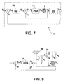
- the regulation of the electronics of the new system is based on a double PID regulation. This means that it has the two regulators linked together, as shown in the diagram of Fig. 7 . This make up will permit the system to be able to control the temperature Ta of a compartment with the determining factor of maximizing the efficiency and minimizing the energy consumption.
- the aim is to heat the radiator 2, 2' as much as possible so that it arrives at the desired temperature Tc as quickly as possible.
- the first PID regulator 16 regulates the temperature of the radiator so that it does not exceed the maximum temperature allowed in this type of equipment (70 degrees centigrade).
- the power supplied to the radiator shall be 100% until the temperature of the radiator arrives at the maximum permitted. When this occurs, the power will progressively decrease thereby saving lots of energy and keeping the radiator at 70°C. It will therefore remain this way until the ambient error is lower than 2 degrees and begins working in the next mode.
- the aim is to adjust the temperature of the radiator to the temperature necessary to achieve the ambient temperature desired.
- This temperature shall be different each time since it will depend on the thermic conditions of the equipment.
- AID Adaptive Proportional Integral Derivative
- the system adapts to the temperature fluctuations caused by disturbances in the environment such as air currents, opening and closing doors, windows, etc. Although it is a slower adjustment, it permits the obtaining of a better efficiency of the radiator and what is more important, a considerable saving of energy. This type of operation permits the connection of two equal radiators consuming the same amount of energy as a single at maximum power consumes.
- Fig. 8 illustrates the power regulation system by means of an insulated gate bipolar transistor (IGBT) 25, which, typically, permits the controlling of high intensities with a very low control output.
- IGBT Insulated Gate Bipolar Transistor
- This power transistor permits a more efficient control through traditional thyristor preventing the electromagnetic interferences produced by the abrupt changes of output current.
- IGBT 25 we can regulate the load by voltage, permitting the control of the power supplied to the load (radiator 2) with a work cycle that goes from 0% to 100% in increments of, preferably, 1%.
- the radiator 2 is supplied by the current of the emitter E of the IGBT 25, whose isolated gate G is supplied by the outlet of a "driver" 27, in series with the outlet of the APID 17.
- a rectifier 26, of continuous outflow connects a terminal with the collector C of the IGBT 25 and the outlet of the load or radiator 2, whose temperature measurement supplies the error signal of the APID 17.
Landscapes
- Engineering & Computer Science (AREA)
- Physics & Mathematics (AREA)
- Automation & Control Theory (AREA)
- General Physics & Mathematics (AREA)
- Combustion & Propulsion (AREA)
- Thermal Sciences (AREA)
- Chemical & Material Sciences (AREA)
- Mechanical Engineering (AREA)
- General Engineering & Computer Science (AREA)
- Medical Informatics (AREA)
- Software Systems (AREA)
- Evolutionary Computation (AREA)
- Computer Vision & Pattern Recognition (AREA)
- Artificial Intelligence (AREA)
- Health & Medical Sciences (AREA)
- Steam Or Hot-Water Central Heating Systems (AREA)
- Central Heating Systems (AREA)
Abstract
Description
- The invention relates to a heating system by means of radiators, which comprises at least a heat-carrying fluid heating boiler which, at least one radiator shell, wherein heat-carrying fluid enters at an inlet temperature through an inlet tube, an impulse pump of the heat-carrying fluid, and means of controlling the ambient temperature through the control of the temperature and flow of the heat-carrying fluid.
- Patent
GB730976 - Patents
GB2174798 GB2270370 GB2298265 FR2832212 GB730976 - In the previously mentioned documents of the state of the art a fluid water flow is established, or of the heat-carrying fluid that it deals with, in closed circuit, which includes a hot water inlet in the upper part of the radiator and a cold water outlet in the lower part thereof. The heating of the water (or heat-carrying fluid) is produced outside of the radiator by means of the electric resistors, in the "heater". That forces the necessity of a double connection from the heater to the radiator, above and below and, given the different dimensions between the connections of the different manufacturers, installing this type of heaters to conventional radiators when a certain degree of autonomy is desired can be complicated and costly.
- Furthermore, the control of this type of heaters is performed thermostatically, by means of all-or-nothing activation of the electrical output of the resistors, depending on whether the ambient temperature is lower or greater than the command temperature, which entails a typically slow and energetically inefficient control. Additionally, a large part of the heating output of the resistor disperses into the air adjacent thereto, losing a large part of the desired "radiant" effect and wide circulation of the heating system based on radiators.
- The purpose of the present invention is to supply a heating system which provides a simultaneous solution to the aforementioned drawbacks.
- For said purpose, the object of the present invention is a new heating system of the type indicated at the beginning, of completely novel concept and function, which in its essentiality is characterized
in that the boiler comprises a heat exchanger made up of at least one block of a paramagnetic material within which circulates the heat-carrying liquid and which comprises electrical resistors which act as heat sources;
in that the means of control of the ambient temperature comprise a sensor of the ambient temperature, at least one sensor of the heat-carrying fluid temperature, and one controller by means of at least one adaptive proportional-integral-derivative (APID) controller whose output variable is the ambient temperature (Ta) and with action on the heat-carrying fluid flow and the inlet temperature thereof (Te) through the thermal output provided by the electrical resistor; and
in that the heat exchanger and the pump are disposed inside the casing or boiler shell, provided with a coupling complementary to the inlet and outlet tubes of at least one radiator shell. - According to another characteristic of the present invention, the inlet tube and the outlet tube of the heat-carrying fluid are disposed one inside the other, and enclosed in a single "monotubular" sheathing.
- The inlet tube and the outlet tube can be disposed one inside the other, and enclosed in a single "monotubular" sheathing, complementary to the outlet and inlet tubes in the boiler shell.
- In accordance with another characteristic of the present invention, said exchanger comprises at least an exchange tube for the circulation of the heat-carrying fluid through the interior of said block of paramagnetic material.
- According to another characteristic of the heating system of the present invention, it comprises a plurality of exchanger tubes in parallel flow.
- In accordance with another characteristic of the invention, the system comprises means of assembling the boiler shell to the radiator shell, for contiguous installation.
- Preferably, the paramagnetic material of the exchanger block is aluminium or an aluminium alloy.
- In accordance with the preferred embodiment of the system of the invention, the controller comprises
- A first PID control, whose entrance is an error signal e□ = |Tc - Ta |, difference between the consign temperature (Tc) and the ambient temperature Ta, and whose outlet is a consign temperature (Tr) of the radiators; and
- An APID control, in tandem with the first PID control, whose entrance is the difference between said consign temperature (Tr) of the radiators and the outlet temperature (Ts) of the radiators, and which actuates on the radiators in order to obtain the final control temperature, or ambient temperature (Ta).
- In the preferred embodiment, said controller comprises
- a means so that, when the e□ error is greater than a pre-set value, the first PID regulator regulates the temperature of the radiator shell or shells so that the same does not exceed a pre-determined maximum temperature, supplying heat as long as 100% of the thermal output thereof does not occur to the radiator shell or shells; and so that, when the pre-determined maximum temperature is reached, it makes the thermal output decrease progressively in order to maintain the radiator shell or shells at this pre-determined maximum temperature until e□ reaches said pre-set value, and
- a means so that, when the e□ error is lesser than said pre-set value, the temperature of the radiator is adjusted to the temperature necessary to achieve the ambient temperature desired.
- In a variant, the controller is adapted to be installed in the interior of the boiler shell.
- Alternatively, the controller can be designed to be installed remotely from the casing, comprising means of transmission of the control signal to the means of actuation of the pump and of the exchanger.
- In this case, the system can remotely administer a plurality of radiator shells, installed at different locations, each one being associated to a respective ambient temperature (Ta), the temperature control means being disposed on at least one centralized remote control and management device.
- According to a preferred embodiment, the system comprises at least one power regulation system by means of an insulated gate bipolar transistor (IGBT) for the regulation "by voltage" of the radiation shells.
- In this case, the radiation shell is supplied by the transmitting current of the IGBT, whose gate is supplied through the outlet of a driver, in series with the APID outlet, comprising a rectifier, of continuous outflow, one of whose terminals is connected to the IGBT collector, and its other terminal being connected to the outlet of the radiation shell.
- Preferably, this regulation system comprises means to control the power supplied to the radiation shell according to a work cycle that goes from 0% to 100% of the power in increments of 1 %.
- In the attached drawings, the forms of preferred embodiments are illustrated in an exemplary and non-limitative, although non-exclusive, manner, of the heating system by means of radiators object of the invention. In said drawings, two merely in illustrative and non-limitative fashion:
- fig. 1
- is a perspective view of a first mode of embodiment of a heating system according to the invention, applied to a towel dryer;
- fig. 2
- is a perspective view, similar to
Fig. 1 , of a second mode of embodiment of a heating system according to the invention, applied in this case to a conventional radiator-emitter heater; - fig. 3
- is a view similar to that of
Fig. 2 , but wherein the boiler shell and sheathing are shown separated from the emitter or radiator themselves; - fig. 4
- is a perspective and detailed view that shows, according to IV of
Fig. 3 , the "monotubular" joining of the boiler shell to the radiator-emitter; - fig. 5
- is a front elevational view of the interior of the boiler shell, illustrating the exchanger, pump, means of regulation and control and ES valves;
- fig. 6
- is an upper plan view, according to VI of
Fig. 5 ; - fig. 7
- is a schematic view of the PID + APID control loop of the heating system of the present invention; and
- fig. 8
- is a view similar to that of
Fig. 7 , but enlarged with the diagram representing the regulation system by means of a insulated gate bipolar transistor (IGBT). - In
Figs. 1 and 2 it can be observed that the heating system of the invention is composed of aradiation shell 2, 2' and ashell 7 of aboiler 1 which can be installed contiguously or adjacently to theradiation shell 2 and 2'. This radiation shell can have any configuration and material. InFig. 1 it is a towel heater 2' for the toilet, and the boiler is adjacent to theheater 2, while inFig. 2 another example has been represented wherein the radiation shell is constituted by a conventional modules radiator-emitter 2. In this case, theemitter radiator 2 and the boiler shell are completely contiguous and are installed practically without solution of continuity, determining a single heating shell. - The heat-carrying fluid can be water, thermic oil or any other fluid with the suitable specific heat and transmission coefficient and convention. The heat-carrying fluid enters the
radiator 2, 2' at an inlet temperature, Te, through aninlet tube 3, and exits the same at an outlet temperature, Ts, through anoutlet tube 4, Te, through aninlet tube 3, and exits the same at an outlet temperature, Ts, through anoutlet tube 4. - A
pump 5 is in charge of driving the heat-carrying fluid, and means of control of the ambient temperature, Ta, are those in charge of administering the boiler, by controlling the temperature and the flow of the heat-carrying fluid. - The first special feature of the system of the present invention is that the
boiler 1 has anexchanger system 6 of the electric type heat, but in which, unlike what is conventional, the heat-carrying fluid is does not make contact with the electrical resistance elements responsible for the heating. The exchanger is comprised of at least oneblock 9 of a paramagnetic material wherein circulates the heat-carrying fluid and which comprises theelectrical resistors 10 which act as a heat source. The absence of contact is beneficial for the maintenance and extension of the operational life of both the resistor and the heat-carrying fluid, due to the fact that is limits the effect of corrosion a great deal, given that the water, for example, is heated through the conduction of the heat though theblock 9. - This material of the
block 9 can be aluminium, an aluminium alloy, or other materials which include aluminium or its alloys in sufficient quantity and proportion. - In
Figs. 5 and 6 an example of embodiment is shown wherein theblock 9 is formed by twomiddle pieces 9', 9" (Fig. 6 ) which when joined both embrace and retain theresistor 10. Awater tube 11 ascends the interior of theblock 9, and again descends through the interior thereof after making an upper loop, in mutually parallel paths therebetween and with respect to theresistor 10 which, in this case, is a rod type resistor. After exiting through the lower part of theblock 9 of theexchanger 6, alower tube 12 conducts the water, or other thermic fluid, towards the inlet of thepump 5, wherefrom its exits towards the outlet of theboiler 1 orinlet 3 to theradiator 2. - In other forms of embodiment of the
exchanger 6, which is not illustrated, it can comprise asingle tube 1 or more than twotubes 1, and more than oneresistor 10 through the interior of theblock 9 of aluminium or similar material or such like. - Another innovative aspect of the present invention is that the means of control of the ambient temperature Ta of a compartment 23 (
Fig. 7 ) comprise a ambient temperature sensor orprobe 13, at least one sensor of the heat-carryingfluid temperature 18, onesafety temperature sensor 19, and one PID-APID controller 15. This is made up of a first Proportional Integral Derivative (PID)controller 16 which actuates on the radiator output, and an Adaptive Proportional Integral Derivative (APID) 17. Thecontroller 15 actuates with the ambient temperature, Ta, as a control parameter and with action on the flow of the heat-carrying fluid, providing a consign temperature Tr of the radiator (to compare with the outlet temperature, Ts, thereof) in order to obtain the inlet temperature, Te, to the radiator through the thermal output contributed by theelectrical resistor 10. Later on its function with regard toFig. 7 will be explained. - The
heat exchanger 6 and thepump 5 are disposed in the interior of a casing, or boiler shell 7 (seeFigs. 3 and5 ), provided with a coupling complementary 22 to theinlet tubes 3 andoutlet tubes 4 or theradiator shell 2, 2'. - In
Figs. 4 through 6 it can be observed that theinlet tube 3 and theoutlet tube 4 of the heat-carrying fluid (with respect to theradiator 2, 2') are disposed one inside the other, and enclosed in a single "monotubular"sheathing 22. Specifically, theinlet tube 3 is concentric, co-axial and inside theoutlet tube 4. - The water or heat-carrying fluid exits the
boiler 1 hot and enters theradiator 2, 2' through thetube 3, at a temperature TE, and exits theradiator 2, 2', at a temperature Ts, lower than Te, through thetube 4, in order to enter theboiler 1. - Thus, this
connection 22 is "universal", as it is directly applicable to conventional "monotube" connections or, if this is not the case, without doing anything more than making simple corrections and reconnections of the inlet and outlet in the case of "dual tube" radiators and emitters, in order to leave them with a single inletoutlet. - In the drawings, an embodiment has been illustrated wherein the
controller 15 is likewise situated in the interior of thecasing 7 of theboiler shell 1. In this case, the electronic and logic of the controller, which can have a microchip, for example, is inside aframe 24 which also incorporates adisplay 20 and akeyboard 21, and/or other inlet/outlet interfaces, accessible from the exterior, as can be observed inFigs. 1 to 3 and5 . Thedisplay 20 and the keyboard are visible through the cover 8 of thesheathing 7 or casing of theboiler shell 1, whose clearance permits access to the interior of theboiler shell 1. - In addition to connections with the
sensors controller 15 has a connection 14 with thepump 5, for the acquisition of information and the transmission of command signals. - In a no less interesting alternative, the
controller 15 is adapted to be installed remotely from thecasing 7 and, therefore, from theboiler 1 and theradiator 2, 2' itself. In this case, means of transmission communicate the control signals to and from the temperature sensors, theboiler 1, thepump 5 and the controller or remote controllers. - In this way, a plurality of
radiator shells 2, 2' can be controlled in a centralized and remote manner, for example, those of a dwelling, office, building, etc. with respective ambient temperatures, and the means ofcontrol 15 of the temperature being disposed on at least one centralized, remote control and management device. This system can form part of a broader home system and can even be controlled by means of instructions transmitted through the Internet. - As has been mentioned previously, the regulation of the electronics of the new system is based on a double PID regulation. This means that it has the two regulators linked together, as shown in the diagram of
Fig. 7 . This make up will permit the system to be able to control the temperature Ta of a compartment with the determining factor of maximizing the efficiency and minimizing the energy consumption. - The difference between the consign temperature Tc and the ambient temperature Ta measured is called ambient error e□. Therefore,

- This allows for a double operation. On the one hand, the operation of mode with an ambient error ea greater than a pre-determined temperature, for example 2 degrees and on the other hand when this error ea is lesser.
- In this mode of work, the aim is to heat the
radiator 2, 2' as much as possible so that it arrives at the desired temperature Tc as quickly as possible. Thefirst PID regulator 16 regulates the temperature of the radiator so that it does not exceed the maximum temperature allowed in this type of equipment (70 degrees centigrade). In this aspect of operation, the power supplied to the radiator shall be 100% until the temperature of the radiator arrives at the maximum permitted. When this occurs, the power will progressively decrease thereby saving lots of energy and keeping the radiator at 70°C. It will therefore remain this way until the ambient error is lower than 2 degrees and begins working in the next mode. - In this mode of work, the aim is to adjust the temperature of the radiator to the temperature necessary to achieve the ambient temperature desired. This temperature shall be different each time since it will depend on the thermic conditions of the equipment. This is achieved with the Adaptive Proportional Integral Derivative (APID) 17 which is implemented on the electronics of the
regulator 15. This regulation is in charge of observing the variations in temperature Ta and adjusting the output to possible thermic changes produced in the atmosphere. - The system adapts to the temperature fluctuations caused by disturbances in the environment such as air currents, opening and closing doors, windows, etc. Although it is a slower adjustment, it permits the obtaining of a better efficiency of the radiator and what is more important, a considerable saving of energy. This type of operation permits the connection of two equal radiators consuming the same amount of energy as a single at maximum power consumes.
- Lastly, illustrated in
Fig. 8 by means of a diagram complementary toFig. 7 is the power regulation system by means of an insulated gate bipolar transistor (IGBT) 25, which, typically, permits the controlling of high intensities with a very low control output. The power supplied to theradiator 2 is done through an IGBT (Insulated Gate Bipolar Transistor). This power transistor permits a more efficient control through traditional thyristor preventing the electromagnetic interferences produced by the abrupt changes of output current. With theIGBT 25 we can regulate the load by voltage, permitting the control of the power supplied to the load (radiator 2) with a work cycle that goes from 0% to 100% in increments of, preferably, 1%. - Specifically, the
radiator 2 is supplied by the current of the emitter E of theIGBT 25, whose isolated gate G is supplied by the outlet of a "driver" 27, in series with the outlet of theAPID 17. Arectifier 26, of continuous outflow, connects a terminal with the collector C of theIGBT 25 and the outlet of the load orradiator 2, whose temperature measurement supplies the error signal of theAPID 17. - The parallel assemblies diode D1 - resistor R1, in series with gate G and diode D2 - resistor R2, in parallel with collector C and emitter E, permit the suitable corrections to the described system, as can be observed in
Fig. 8 . - The nature of the present invention having been sufficiently described, as well as the way of putting it into practice, it must be pointed out that everything is subject to changes in detail as long as it does not alter, change or modify its main principle.
Claims (16)
- Heating system by means of radiators, which comprises at least one heat-carrying fluid heating boiler (1), at least one radiator shell (2, 2'), wherein heat-carrying fluid enters at an inlet temperature (Te) through an inlet tube (3), and wherefrom it exits at an outlet temperature (Ts) through an outlet tube (4), an impulse pump (5) of the heat-carrying fluid, and means of controlling the ambient temperature (Ta) through the control of the temperature and flow of the heat-carrying fluid, characterized in that
the boiler (1) comprises a heat exchanger (6) made up of at least one block (9) of a paramagnetic material within which circulates the heat-carrying liquid and which comprises electrical resistors (10) which act as heat sources;
the means of control of the ambient temperature comprise a sensor of the ambient temperature, at least one sensor of the heat-carrying fluid temperature, and one controller (15) by means of at least one adaptive proportional-integral-derivative (APID) controller whose output variable is the ambient temperature (Ta) and with action on the heat-carrying fluid flow and the inlet temperature thereof (Te) through the thermal output provided by the electrical resistor (10); and
the heat exchanger (6) and the pump (5) are disposed inside the casing or boiler shell (7), provided with a coupling complementary to the inlet and outlet tubes of at least one radiator shell (2, 2'). - Heating system according to claim 1, characterized in that the inlet tube (3) and the outlet tube (4) of the heat-carrying fluid are disposed one inside the other, and enclosed in a single "monotubular" sheathing (22).
- Heating system according to claim 2, characterized in that inlet tube (3) and the outlet tube (4) of the heat-carrying fluid are disposed one inside the other, and enclosed in a single "monotubular" sheathing, complementary to the outlet and inlet tubes in the boiler shell.
- Heating system according to claim 1, characterized in that said exchanger (6) comprises at least one exchange tube (11) for the circulation of the heat-carrying fluid through the interior of said block (9) of paramagnetic material.
- Heating system according to claim 4, characterized in that it comprises a plurality of parallel flow exchanger tubes.
- Heating system according to claim 1, characterized in that it comprises means of assembling the boiler shell to the radiator shell, for the contiguous installation thereof.
- Heating system according to claim 1, characterized in that the paramagnetic material of the block (9) of the exchanger (6) is aluminium or an aluminium alloy.
- Heating system according to claim 1, characterized in that said controller (15) comprises
a first PID control (16), whose entrance is an error signal ea = |Tc - Ta |, difference between the consign temperature (Tc) and the ambient temperature Ta, and whose outlet is a consign temperature (Tr) of the radiators (2, 2'); and
an APID control (17), in tandem with the first PID control (16), whose entrance is the difference between said consign temperature (Tr) of the radiators (2, 2') and the outlet temperature (Ts) of the radiators, and which actuates on the radiators (2, 2') in order to obtain the final control temperature, or ambient temperature (Ta). - Heating system according to claim 8, characterized in that said controller (15) comprises means so that, when the ea error is greater than a pre-set value, the first PID regulator (16) regulates the temperature of the radiator shell or shells (2, 2') so that the same does not exceed a pre-determined maximum temperature, supplying heat as long as 100% of the thermal output thereof does not occur to the radiator shell or shells (2, 2'); and so that, when the pre-determined maximum temperature is reached, it makes the thermal output decrease progressively in order to maintain the radiator shell or shells (2, 2') at this pre-determined maximum temperature until ea reaches said pre-set value.
- Heating system according to claim 9, characterized in that said controller (15) comprises means so that, when the ea error is lesser than said pre-set value, the temperature of the radiator is adjusted to the temperature necessary to achieve the ambient temperature desired.
- Heating system according to any of claims 1, 8, 9 or 10, characterized in that the controller (15) is adapted to be installed in the interior of the boiler shell (7).
- Heating system according to any of claims 1, 8, 9 or 10, characterized in that the controller (15) is adapted to be installed remotely from the casing (7), comprising means of transmission of the control signal to the means of actuation of the pump (5) and of the exchanger (6).
- Heating system according to claim 12, characterized in that it comprises a plurality of radiator shells (2, 2'), adapted to be installed at different locations, and each one being associated to a respective ambient temperature (Ta), the temperature control means (15) being disposed on at least one centralized remote control and management device.
- Heating system according to any of the previous claims, characterized in that it comprises at least one power regulation system by means of an insulated gate bipolar transistor IGBT (25) for the regulation "by voltage" of the radiation shells (2, 2').
- Heating system according to claim 14, characterized in that the radiation shell (2, 2') is supplied by the emitting current (E) of the IGBT (25), whose gate (G) is supplied through the outlet of a "driver" (27), in series with the APID outlet (17), comprising a rectifier (26), of continuous outflow, one of whose terminals is connected to the IGBT (25) collector (C), and its other terminal being connected to the outlet of the radiation shell (2, 2').
- Heating system according to claims 14 or 15, characterized in that said regulation system comprises means to control the power supplied to the radiation shell (2, 2') according to a work cycle that goes from 0% to 100% of the power in increments of 1%.
Applications Claiming Priority (2)
| Application Number | Priority Date | Filing Date | Title |
|---|---|---|---|
| ES200602035A ES2289952B1 (en) | 2006-07-28 | 2006-07-28 | HEATING SYSTEM BY RADIATORS. |
| PCT/ES2007/000449 WO2008012387A1 (en) | 2006-07-28 | 2007-07-20 | Radiator heating system |
Publications (4)
| Publication Number | Publication Date |
|---|---|
| EP2048565A1 true EP2048565A1 (en) | 2009-04-15 |
| EP2048565A4 EP2048565A4 (en) | 2011-10-19 |
| EP2048565B1 EP2048565B1 (en) | 2013-06-19 |
| EP2048565B8 EP2048565B8 (en) | 2013-07-24 |
Family
ID=38961570
Family Applications (1)
| Application Number | Title | Priority Date | Filing Date |
|---|---|---|---|
| EP07803636.5A Not-in-force EP2048565B8 (en) | 2006-07-28 | 2007-07-20 | Radiator heating system |
Country Status (3)
| Country | Link |
|---|---|
| EP (1) | EP2048565B8 (en) |
| ES (1) | ES2289952B1 (en) |
| WO (1) | WO2008012387A1 (en) |
Cited By (1)
| Publication number | Priority date | Publication date | Assignee | Title |
|---|---|---|---|---|
| GB2548624A (en) * | 2016-03-24 | 2017-09-27 | Enviroheat Het Ltd | Heating apparatus |
Families Citing this family (1)
| Publication number | Priority date | Publication date | Assignee | Title |
|---|---|---|---|---|
| GB2576947B (en) | 2018-09-10 | 2020-09-09 | Dyson Technology Ltd | A method of controlling a haircare appliance |
Family Cites Families (11)
| Publication number | Priority date | Publication date | Assignee | Title |
|---|---|---|---|---|
| GB730976A (en) | 1952-08-06 | 1955-06-01 | Harry Harvey | Improvements in and relating to electrically heated hot-water radiators |
| GB8411363D0 (en) * | 1984-05-03 | 1984-06-06 | Honeywell Control Syst | Temperature control system |
| GB2174798B (en) * | 1985-05-09 | 1988-04-27 | Megaglow Ltd | Water heater |
| US5819845A (en) * | 1990-11-24 | 1998-10-13 | Samsung Electronics Co., Ltd. | Temperature control method for a heating/cooling system |
| GB2270370B (en) | 1992-09-07 | 1996-06-12 | Caradon Mira Ltd | Heat exchanger |
| US6264111B1 (en) * | 1993-06-16 | 2001-07-24 | Siemens Building Technologies, Inc. | Proportional-integral-derivative controller having adaptive control capability |
| GB9503622D0 (en) | 1995-02-23 | 1995-04-12 | Crampton Frederick A | Space heating apparatus |
| FR2832212B1 (en) * | 2001-11-13 | 2005-07-22 | Henri Louis Russi | HEAT PUMP RADIATOR |
| FR2839372B1 (en) * | 2002-05-06 | 2005-01-07 | Martinez Thierry | ENERGY CONTROL AND MANAGEMENT SYSTEM |
| US6783080B2 (en) * | 2002-05-16 | 2004-08-31 | Advanced Thermal Sciences Corp. | Systems and methods for controlling temperatures of process tools |
| JP2006177611A (en) * | 2004-12-22 | 2006-07-06 | Yamaha Corp | Electronic heating and cooling device |
-
2006
- 2006-07-28 ES ES200602035A patent/ES2289952B1/en not_active Expired - Fee Related
-
2007
- 2007-07-20 EP EP07803636.5A patent/EP2048565B8/en not_active Not-in-force
- 2007-07-20 WO PCT/ES2007/000449 patent/WO2008012387A1/en not_active Ceased
Cited By (3)
| Publication number | Priority date | Publication date | Assignee | Title |
|---|---|---|---|---|
| GB2548624A (en) * | 2016-03-24 | 2017-09-27 | Enviroheat Het Ltd | Heating apparatus |
| WO2017163082A1 (en) * | 2016-03-24 | 2017-09-28 | Enviroheat Het Limited | Heating apparatus |
| GB2548624B (en) * | 2016-03-24 | 2020-09-16 | Enviroheat Het Ltd | Heating apparatus |
Also Published As
| Publication number | Publication date |
|---|---|
| ES2289952B1 (en) | 2008-12-16 |
| EP2048565B8 (en) | 2013-07-24 |
| EP2048565A4 (en) | 2011-10-19 |
| WO2008012387A1 (en) | 2008-01-31 |
| ES2289952A1 (en) | 2008-02-01 |
| WO2008012387A8 (en) | 2009-02-19 |
| EP2048565B1 (en) | 2013-06-19 |
Similar Documents
| Publication | Publication Date | Title |
|---|---|---|
| GB2452043A (en) | Radiator thermostatic control | |
| KR100310330B1 (en) | Multifunctional temperature controller for hotwater ondol heating system | |
| JP2015507276A (en) | Improvement to temperature control unit for building heating system | |
| US20100298992A1 (en) | System for Controlling the Heating and Housing Units in a Building | |
| Ali et al. | Development and evaluation of an automatic steam radiator control system for retrofitting legacy heating systems in existing buildings | |
| CN107543243A (en) | A kind of method and system of public building heating energy | |
| EP2048565B1 (en) | Radiator heating system | |
| EP4288713B1 (en) | Heating installation for premises and method of controlling a premises heating installation | |
| US4369765A (en) | Supplemental heating system using solar radiation | |
| SK6502001A3 (en) | Apparatus for detecting the heat output of a radiator and regulating the room temperature | |
| EP4071414B1 (en) | Method, system and computer program product for controlling a heat generator | |
| KR19980018617A (en) | Hydraulic assembly for hot water and sanitary water | |
| US7628337B2 (en) | Secondary heating system | |
| EP1003089B2 (en) | Demand-responsive control for a heat transfer device | |
| EP4113017A1 (en) | A heating device for performing instant domestic hot water supply and space heating simultaneously and a method of operation thereof | |
| CN205919414U (en) | Frostproofing hanging stove of intelligence | |
| CN218544700U (en) | Hot temperature control unit and temperature control device | |
| CN116086019A (en) | Water mixing control method and system for constant-temperature hot water controller | |
| US12253282B2 (en) | Double-circuit electric boiler (variants) | |
| Crommelin et al. | The influence of modifications in a central heating system of a dwelling on the energy consumption, calculated with a dynamic model | |
| CN2648215Y (en) | Temperature control valve for heating system | |
| CN201203285Y (en) | Solar water heater capable of controlling temperature | |
| WO2025229445A1 (en) | Methods and systems and apparatus to support reduced energy and water usage | |
| WO2025229443A1 (en) | Domestic hot water system | |
| CN209710335U (en) | A kind of farm's heat preservation lamp controller |
Legal Events
| Date | Code | Title | Description |
|---|---|---|---|
| PUAI | Public reference made under article 153(3) epc to a published international application that has entered the european phase |
Free format text: ORIGINAL CODE: 0009012 |
|
| AK | Designated contracting states |
Kind code of ref document: A1 Designated state(s): AT BE BG CH CY CZ DE DK EE ES FI FR GB GR HU IE IS IT LI LT LU LV MC MT NL PL PT RO SE SI SK TR |
|
| AX | Request for extension of the european patent |
Extension state: AL BA HR MK RS |
|
| 17P | Request for examination filed |
Effective date: 20090616 |
|
| RBV | Designated contracting states (corrected) |
Designated state(s): AT BE BG CH CY CZ DE DK EE ES FI FR GB GR HU IE IS IT LI LT LU LV MC MT NL PL PT RO SE SI SK TR |
|
| RAP1 | Party data changed (applicant data changed or rights of an application transferred) |
Owner name: MARTINEZ, THIERRY M. Owner name: CARBONNIER, JEAN-LUIS Owner name: JVV GRUP MONTAJES Y DESARROLLOS DE PROYECTOS ELECT |
|
| RIN1 | Information on inventor provided before grant (corrected) |
Inventor name: VERDAGUER I VILLACAMPA, JORDI Inventor name: MARTINEZ, THIERRY M. |
|
| R17P | Request for examination filed (corrected) |
Effective date: 20090616 |
|
| A4 | Supplementary search report drawn up and despatched |
Effective date: 20110920 |
|
| RIC1 | Information provided on ipc code assigned before grant |
Ipc: G05D 23/19 20060101AFI20110914BHEP Ipc: G05B 11/36 20060101ALI20110914BHEP Ipc: F24H 3/00 20060101ALI20110914BHEP Ipc: G05B 11/42 20060101ALI20110914BHEP Ipc: G05B 13/02 20060101ALI20110914BHEP |
|
| DAX | Request for extension of the european patent (deleted) | ||
| GRAJ | Information related to disapproval of communication of intention to grant by the applicant or resumption of examination proceedings by the epo deleted |
Free format text: ORIGINAL CODE: EPIDOSDIGR1 |
|
| GRAP | Despatch of communication of intention to grant a patent |
Free format text: ORIGINAL CODE: EPIDOSNIGR1 |
|
| RIN1 | Information on inventor provided before grant (corrected) |
Inventor name: VERDAGUER I VILLACAMPA, JORDI Inventor name: MARTINEZ, THIERRY M. Inventor name: CARBONNIER, JEAN-LUIS |
|
| GRAS | Grant fee paid |
Free format text: ORIGINAL CODE: EPIDOSNIGR3 |
|
| GRAA | (expected) grant |
Free format text: ORIGINAL CODE: 0009210 |
|
| RAP1 | Party data changed (applicant data changed or rights of an application transferred) |
Owner name: MARTINEZ, THIERRY M. Owner name: CARBONNIER, JEAN-LUIS |
|
| AK | Designated contracting states |
Kind code of ref document: B1 Designated state(s): AT BE BG CH CY CZ DE DK EE ES FI FR GB GR HU IE IS IT LI LT LU LV MC MT NL PL PT RO SE SI SK TR |
|
| REG | Reference to a national code |
Ref country code: GB Ref legal event code: FG4D |
|
| RIN2 | Information on inventor provided after grant (corrected) |
Inventor name: VERDAGUER I VILLACAMPA, JORDI Inventor name: MARTINEZ, THIERRY M. Inventor name: CARBONNIER, JEAN-LOUIS |
|
| REG | Reference to a national code |
Ref country code: CH Ref legal event code: EP |
|
| REG | Reference to a national code |
Ref country code: AT Ref legal event code: REF Ref document number: 617987 Country of ref document: AT Kind code of ref document: T Effective date: 20130715 |
|
| REG | Reference to a national code |
Ref country code: IE Ref legal event code: FG4D |
|
| REG | Reference to a national code |
Ref country code: DE Ref legal event code: R096 Ref document number: 602007031158 Country of ref document: DE Effective date: 20130814 |
|
| PG25 | Lapsed in a contracting state [announced via postgrant information from national office to epo] |
Ref country code: FI Free format text: LAPSE BECAUSE OF FAILURE TO SUBMIT A TRANSLATION OF THE DESCRIPTION OR TO PAY THE FEE WITHIN THE PRESCRIBED TIME-LIMIT Effective date: 20130619 Ref country code: ES Free format text: LAPSE BECAUSE OF FAILURE TO SUBMIT A TRANSLATION OF THE DESCRIPTION OR TO PAY THE FEE WITHIN THE PRESCRIBED TIME-LIMIT Effective date: 20130930 Ref country code: LT Free format text: LAPSE BECAUSE OF FAILURE TO SUBMIT A TRANSLATION OF THE DESCRIPTION OR TO PAY THE FEE WITHIN THE PRESCRIBED TIME-LIMIT Effective date: 20130619 Ref country code: SI Free format text: LAPSE BECAUSE OF FAILURE TO SUBMIT A TRANSLATION OF THE DESCRIPTION OR TO PAY THE FEE WITHIN THE PRESCRIBED TIME-LIMIT Effective date: 20130619 Ref country code: SE Free format text: LAPSE BECAUSE OF FAILURE TO SUBMIT A TRANSLATION OF THE DESCRIPTION OR TO PAY THE FEE WITHIN THE PRESCRIBED TIME-LIMIT Effective date: 20130619 |
|
| PGFP | Annual fee paid to national office [announced via postgrant information from national office to epo] |
Ref country code: CH Payment date: 20130821 Year of fee payment: 7 Ref country code: DE Payment date: 20130730 Year of fee payment: 7 |
|
| REG | Reference to a national code |
Ref country code: AT Ref legal event code: MK05 Ref document number: 617987 Country of ref document: AT Kind code of ref document: T Effective date: 20130619 |
|
| REG | Reference to a national code |
Ref country code: LT Ref legal event code: MG4D |
|
| PG25 | Lapsed in a contracting state [announced via postgrant information from national office to epo] |
Ref country code: BG Free format text: LAPSE BECAUSE OF FAILURE TO SUBMIT A TRANSLATION OF THE DESCRIPTION OR TO PAY THE FEE WITHIN THE PRESCRIBED TIME-LIMIT Effective date: 20130919 |
|
| REG | Reference to a national code |
Ref country code: NL Ref legal event code: VDEP Effective date: 20130619 |
|
| PG25 | Lapsed in a contracting state [announced via postgrant information from national office to epo] |
Ref country code: LV Free format text: LAPSE BECAUSE OF FAILURE TO SUBMIT A TRANSLATION OF THE DESCRIPTION OR TO PAY THE FEE WITHIN THE PRESCRIBED TIME-LIMIT Effective date: 20130619 |
|
| PG25 | Lapsed in a contracting state [announced via postgrant information from national office to epo] |
Ref country code: AT Free format text: LAPSE BECAUSE OF FAILURE TO SUBMIT A TRANSLATION OF THE DESCRIPTION OR TO PAY THE FEE WITHIN THE PRESCRIBED TIME-LIMIT Effective date: 20130619 Ref country code: BE Free format text: LAPSE BECAUSE OF FAILURE TO SUBMIT A TRANSLATION OF THE DESCRIPTION OR TO PAY THE FEE WITHIN THE PRESCRIBED TIME-LIMIT Effective date: 20130619 Ref country code: EE Free format text: LAPSE BECAUSE OF FAILURE TO SUBMIT A TRANSLATION OF THE DESCRIPTION OR TO PAY THE FEE WITHIN THE PRESCRIBED TIME-LIMIT Effective date: 20130619 Ref country code: SK Free format text: LAPSE BECAUSE OF FAILURE TO SUBMIT A TRANSLATION OF THE DESCRIPTION OR TO PAY THE FEE WITHIN THE PRESCRIBED TIME-LIMIT Effective date: 20130619 Ref country code: CY Free format text: LAPSE BECAUSE OF FAILURE TO SUBMIT A TRANSLATION OF THE DESCRIPTION OR TO PAY THE FEE WITHIN THE PRESCRIBED TIME-LIMIT Effective date: 20130731 Ref country code: IS Free format text: LAPSE BECAUSE OF FAILURE TO SUBMIT A TRANSLATION OF THE DESCRIPTION OR TO PAY THE FEE WITHIN THE PRESCRIBED TIME-LIMIT Effective date: 20131019 Ref country code: PT Free format text: LAPSE BECAUSE OF FAILURE TO SUBMIT A TRANSLATION OF THE DESCRIPTION OR TO PAY THE FEE WITHIN THE PRESCRIBED TIME-LIMIT Effective date: 20131021 Ref country code: CZ Free format text: LAPSE BECAUSE OF FAILURE TO SUBMIT A TRANSLATION OF THE DESCRIPTION OR TO PAY THE FEE WITHIN THE PRESCRIBED TIME-LIMIT Effective date: 20130619 |
|
| PG25 | Lapsed in a contracting state [announced via postgrant information from national office to epo] |
Ref country code: NL Free format text: LAPSE BECAUSE OF FAILURE TO SUBMIT A TRANSLATION OF THE DESCRIPTION OR TO PAY THE FEE WITHIN THE PRESCRIBED TIME-LIMIT Effective date: 20130619 Ref country code: RO Free format text: LAPSE BECAUSE OF FAILURE TO SUBMIT A TRANSLATION OF THE DESCRIPTION OR TO PAY THE FEE WITHIN THE PRESCRIBED TIME-LIMIT Effective date: 20130619 Ref country code: PL Free format text: LAPSE BECAUSE OF FAILURE TO SUBMIT A TRANSLATION OF THE DESCRIPTION OR TO PAY THE FEE WITHIN THE PRESCRIBED TIME-LIMIT Effective date: 20130619 |
|
| PG25 | Lapsed in a contracting state [announced via postgrant information from national office to epo] |
Ref country code: CY Free format text: LAPSE BECAUSE OF FAILURE TO SUBMIT A TRANSLATION OF THE DESCRIPTION OR TO PAY THE FEE WITHIN THE PRESCRIBED TIME-LIMIT Effective date: 20130619 Ref country code: MC Free format text: LAPSE BECAUSE OF FAILURE TO SUBMIT A TRANSLATION OF THE DESCRIPTION OR TO PAY THE FEE WITHIN THE PRESCRIBED TIME-LIMIT Effective date: 20130619 |
|
| REG | Reference to a national code |
Ref country code: IE Ref legal event code: MM4A |
|
| PLBE | No opposition filed within time limit |
Free format text: ORIGINAL CODE: 0009261 |
|
| STAA | Information on the status of an ep patent application or granted ep patent |
Free format text: STATUS: NO OPPOSITION FILED WITHIN TIME LIMIT |
|
| PG25 | Lapsed in a contracting state [announced via postgrant information from national office to epo] |
Ref country code: DK Free format text: LAPSE BECAUSE OF FAILURE TO SUBMIT A TRANSLATION OF THE DESCRIPTION OR TO PAY THE FEE WITHIN THE PRESCRIBED TIME-LIMIT Effective date: 20130619 |
|
| 26N | No opposition filed |
Effective date: 20140320 |
|
| GBPC | Gb: european patent ceased through non-payment of renewal fee |
Effective date: 20130919 |
|
| PG25 | Lapsed in a contracting state [announced via postgrant information from national office to epo] |
Ref country code: IT Free format text: LAPSE BECAUSE OF FAILURE TO SUBMIT A TRANSLATION OF THE DESCRIPTION OR TO PAY THE FEE WITHIN THE PRESCRIBED TIME-LIMIT Effective date: 20130619 |
|
| REG | Reference to a national code |
Ref country code: DE Ref legal event code: R097 Ref document number: 602007031158 Country of ref document: DE Effective date: 20140320 |
|
| PG25 | Lapsed in a contracting state [announced via postgrant information from national office to epo] |
Ref country code: IE Free format text: LAPSE BECAUSE OF NON-PAYMENT OF DUE FEES Effective date: 20130720 Ref country code: GB Free format text: LAPSE BECAUSE OF NON-PAYMENT OF DUE FEES Effective date: 20130919 |
|
| REG | Reference to a national code |
Ref country code: DE Ref legal event code: R119 Ref document number: 602007031158 Country of ref document: DE |
|
| REG | Reference to a national code |
Ref country code: CH Ref legal event code: PL |
|
| PG25 | Lapsed in a contracting state [announced via postgrant information from national office to epo] |
Ref country code: CH Free format text: LAPSE BECAUSE OF NON-PAYMENT OF DUE FEES Effective date: 20140731 Ref country code: DE Free format text: LAPSE BECAUSE OF NON-PAYMENT OF DUE FEES Effective date: 20150203 Ref country code: LI Free format text: LAPSE BECAUSE OF NON-PAYMENT OF DUE FEES Effective date: 20140731 |
|
| REG | Reference to a national code |
Ref country code: DE Ref legal event code: R119 Ref document number: 602007031158 Country of ref document: DE Effective date: 20150203 |
|
| PG25 | Lapsed in a contracting state [announced via postgrant information from national office to epo] |
Ref country code: MT Free format text: LAPSE BECAUSE OF FAILURE TO SUBMIT A TRANSLATION OF THE DESCRIPTION OR TO PAY THE FEE WITHIN THE PRESCRIBED TIME-LIMIT Effective date: 20130619 Ref country code: TR Free format text: LAPSE BECAUSE OF FAILURE TO SUBMIT A TRANSLATION OF THE DESCRIPTION OR TO PAY THE FEE WITHIN THE PRESCRIBED TIME-LIMIT Effective date: 20130619 |
|
| PG25 | Lapsed in a contracting state [announced via postgrant information from national office to epo] |
Ref country code: LU Free format text: LAPSE BECAUSE OF NON-PAYMENT OF DUE FEES Effective date: 20130720 Ref country code: HU Free format text: LAPSE BECAUSE OF FAILURE TO SUBMIT A TRANSLATION OF THE DESCRIPTION OR TO PAY THE FEE WITHIN THE PRESCRIBED TIME-LIMIT; INVALID AB INITIO Effective date: 20070720 |
|
| PG25 | Lapsed in a contracting state [announced via postgrant information from national office to epo] |
Ref country code: GR Free format text: LAPSE BECAUSE OF NON-PAYMENT OF DUE FEES Effective date: 20130619 |
|
| REG | Reference to a national code |
Ref country code: FR Ref legal event code: PLFP Year of fee payment: 10 |
|
| REG | Reference to a national code |
Ref country code: FR Ref legal event code: PLFP Year of fee payment: 11 |
|
| REG | Reference to a national code |
Ref country code: FR Ref legal event code: PLFP Year of fee payment: 12 |
|
| PGFP | Annual fee paid to national office [announced via postgrant information from national office to epo] |
Ref country code: FR Payment date: 20190719 Year of fee payment: 13 |
|
| PG25 | Lapsed in a contracting state [announced via postgrant information from national office to epo] |
Ref country code: FR Free format text: LAPSE BECAUSE OF NON-PAYMENT OF DUE FEES Effective date: 20200731 |