EP2048393A2 - "Rotary shaft coupling" - Google Patents
"Rotary shaft coupling" Download PDFInfo
- Publication number
- EP2048393A2 EP2048393A2 EP08164697A EP08164697A EP2048393A2 EP 2048393 A2 EP2048393 A2 EP 2048393A2 EP 08164697 A EP08164697 A EP 08164697A EP 08164697 A EP08164697 A EP 08164697A EP 2048393 A2 EP2048393 A2 EP 2048393A2
- Authority
- EP
- European Patent Office
- Prior art keywords
- teeth
- rotary shaft
- shaft coupling
- rotation
- outer teeth
- Prior art date
- Legal status (The legal status is an assumption and is not a legal conclusion. Google has not performed a legal analysis and makes no representation as to the accuracy of the status listed.)
- Withdrawn
Links
- 230000008878 coupling Effects 0.000 title claims abstract description 55
- 238000010168 coupling process Methods 0.000 title claims abstract description 55
- 238000005859 coupling reaction Methods 0.000 title claims abstract description 55
- 230000005540 biological transmission Effects 0.000 claims abstract description 18
- 239000004519 grease Substances 0.000 claims description 5
- 238000007789 sealing Methods 0.000 claims description 2
- 238000010586 diagram Methods 0.000 description 18
- 238000006073 displacement reaction Methods 0.000 description 4
- 239000011347 resin Substances 0.000 description 3
- 229920005989 resin Polymers 0.000 description 3
- 230000000694 effects Effects 0.000 description 2
- 230000002787 reinforcement Effects 0.000 description 2
- 238000004519 manufacturing process Methods 0.000 description 1
- 230000004048 modification Effects 0.000 description 1
- 238000012986 modification Methods 0.000 description 1
- 230000003014 reinforcing effect Effects 0.000 description 1
- 238000000926 separation method Methods 0.000 description 1
Images




Classifications
-
- F—MECHANICAL ENGINEERING; LIGHTING; HEATING; WEAPONS; BLASTING
- F16—ENGINEERING ELEMENTS AND UNITS; GENERAL MEASURES FOR PRODUCING AND MAINTAINING EFFECTIVE FUNCTIONING OF MACHINES OR INSTALLATIONS; THERMAL INSULATION IN GENERAL
- F16D—COUPLINGS FOR TRANSMITTING ROTATION; CLUTCHES; BRAKES
- F16D3/00—Yielding couplings, i.e. with means permitting movement between the connected parts during the drive
- F16D3/02—Yielding couplings, i.e. with means permitting movement between the connected parts during the drive adapted to specific functions
-
- F—MECHANICAL ENGINEERING; LIGHTING; HEATING; WEAPONS; BLASTING
- F16—ENGINEERING ELEMENTS AND UNITS; GENERAL MEASURES FOR PRODUCING AND MAINTAINING EFFECTIVE FUNCTIONING OF MACHINES OR INSTALLATIONS; THERMAL INSULATION IN GENERAL
- F16D—COUPLINGS FOR TRANSMITTING ROTATION; CLUTCHES; BRAKES
- F16D3/00—Yielding couplings, i.e. with means permitting movement between the connected parts during the drive
- F16D3/02—Yielding couplings, i.e. with means permitting movement between the connected parts during the drive adapted to specific functions
- F16D3/04—Yielding couplings, i.e. with means permitting movement between the connected parts during the drive adapted to specific functions specially adapted to allow radial displacement, e.g. Oldham couplings
-
- F—MECHANICAL ENGINEERING; LIGHTING; HEATING; WEAPONS; BLASTING
- F16—ENGINEERING ELEMENTS AND UNITS; GENERAL MEASURES FOR PRODUCING AND MAINTAINING EFFECTIVE FUNCTIONING OF MACHINES OR INSTALLATIONS; THERMAL INSULATION IN GENERAL
- F16D—COUPLINGS FOR TRANSMITTING ROTATION; CLUTCHES; BRAKES
- F16D3/00—Yielding couplings, i.e. with means permitting movement between the connected parts during the drive
- F16D3/16—Universal joints in which flexibility is produced by means of pivots or sliding or rolling connecting parts
- F16D3/18—Universal joints in which flexibility is produced by means of pivots or sliding or rolling connecting parts the coupling parts (1) having slidably-interengaging teeth
Definitions
- the present invention relates to a rotary shaft coupling.
- the present invention relates to a rotary shaft coupling that is suitable for transmitting rotation between rotational axes disposed such that axial ends oppose each other.
- a rotary shaft coupling is used to smoothly transmit rotation between rotational axes of which shaft cores may be opposing each other in a misaligned state.
- the rotary shaft coupling using flexible joints has disadvantages such as having a large number of components, being heavy, rotational unevenness during rotation transmission, and being high in manufacturing cost.
- the rotary shaft coupling has a pair of joints having a same shape.
- a concave and convex section is evenly disposed on an outer circumference of a disc-shaped seat.
- a rotational axis is fixed onto a center of the disc-shaped seat.
- the pair of joints mesh with each other such that the concave and convex sections oppose each other with matching phases.
- Patent Literature 1 Japanese Patent Laid-open Publication No. Heisei 10-331860
- the concave and convex sections are shaped and positioned such that the joints mesh with each other with adequate clearance therebetween to absorb shaft core misalignment between the axes.
- the concave and convex section is formed such that a tip section of a cylinder is alternately cut on a vertical direction cutting plane extending in a radial direction and a horizontal direction cutting plane extending in a circumferential direction that connects two adjacent vertical direction cutting planes.
- An object of the present invention is to provide a rotary shaft coupling that can accurately transmit rotation of one rotational axis to another rotational axis and has excellent durability, without generating noise.
- a rotary shaft coupling is a rotary shaft coupling including a pair of joint halves that are respectively attached to opposing axial end sections and transmit rotation of one axis to another axis.
- outer teeth of a gear are provided on one joint half.
- Inner teeth that mesh with the outer teeth and have a same number of teeth as the outer teeth are provided on the other joint half.
- the outer teeth and the inner teeth are formed to absorb shaft core misalignment between both axes and perform rotation transmission by having an involuted tooth profile of a same module and a tooth flank of the involuted tooth profile displaced in either one of a tangential line direction and a radial direction, or both.
- the outer teeth and the inner teeth formed having an involuted tooth profile of a same module and a tooth flank of the involuted tooth profile displaced in a circumferential direction, always successfully mesh. Therefore, even when shaft core misalignment is present between rotation axes, the rotation of one rotation axis can be accurately transmitted to the other rotation axis. Durability can be increased without noise being generated.
- the shaft core misalignment is one of an axial misalignment in a parallel direction of axial centers of both axes and angular misalignment in a relative angular direction of the axial centers of both axes, or both.
- the rotation can be successfully transmitted in a similar manner as that according to the first aspect, even when shaft core misalignment that is one of an axial misalignment in a parallel direction of axial centers of both axes and angular misalignment in a relative angular direction of the axial centers of both axes, or both, occurs.
- a meshing ratio between the outer teeth and the inner teeth is one or more.
- the outer teeth and the inner teeth always successfully mesh with more certainty. Therefore, rotation transmission can be performed without rotation unevenness. Moreover, rotation transmission torque can be increased.
- a number of teeth of the outer teeth and the inner teeth are six teeth to eight teeth.
- rigidity of the outer teeth and the inner teeth can be kept high, and rotation transmission can be performed smoothly.
- a spring is attached that applied elastic force rotating the both joint halves in opposite directions.
- the outer teeth and the inner teeth can always mesh.
- a ring-shaped elastic body is attached to outer circumferential surfaces of the outer teeth and the inner teeth.
- separation of the outer teeth and the inner teeth can be prevented by elasticity of the elastic body in the circumferential direction, and the outer teeth and the inner teeth can always mesh.
- the ring-shaped elastic body is a rubber cover or an O-ring sealing an outer circumferential section of a meshing section of the pair of joint halves.
- an area between the joint halves can be sealed through use of the rubber cover that seals the outer circumferential sections of the joint halves. Dust-control and sound-proofing can be achieved.
- a commercially-available, general-purpose O-ring can be used when the O-ring is used, thereby lowering cost.
- an air-tight space formed on an inner side of the rubber cover is filled with grease.
- rotation transmission can be made smoother by the grease, and wear in the outer teeth and the inner teeth can be prevented.
- the rotary shaft coupling of the present invention is configured and operated as described above. Therefore, even when shaft core misalignment is present between rotation axes, rotation from one rotation axis can be accurately transmitted to another rotation axis. Superior effects, such as increased durability, can be achieved without noise being generated.
- Fig. 1 to Fig. 4 are diagrams of a rotary shaft coupling according to a first embodiment of the present invention.
- a rotary shaft coupling 1 includes a pair of joint halves, a joint half 2a and a joint half 2b, that are respectively attached to ends of opposing rotation axis 11a and rotation axis 11b.
- the pair of joint halves 2a and 2b transmit rotation of one axis to the other axis.
- the rotary shaft coupling 1 is formed having a gear with eight teeth.
- a boss section 4a is formed in a center of a disc-shaped main body 3a.
- a center hole 5a having a rectangular cross-section is formed on the boss section 4a.
- the center hole 5a fits with an axial end section 12a of a rotation axis 11a in a serrated manner.
- the axial end section 12a has a rectangular cross-section.
- a boss section 4b is formed in a center of a disc-shaped main body 3b.
- a center hole 5b having a rectangular cross-section is formed on the boss section 4b.
- the center hole 5b fits with an axial end section 12b of a rotation axis 11b in a serrated manner.
- the axial end section 12b has a rectangular cross-section.
- Outer teeth 6a of a gear having eight teeth are provided on one surface of opposing surfaces of the main body 3a of the joint half 2a and the main body 3b of the joint half 3b.
- Inner teeth 6b of a gear having the same number of teeth as the outer teeth 6a are provided on the other surface.
- the inner teeth 6b mesh with the outer teeth 6a.
- the outer teeth 6a and the inner teeth 6b each have an involuted tooth profile of a same module.
- the outer teeth 6a and the inner teeth 6b are formed such that a tooth flank of the involuted tooth profile is displaced in either one of a tangential line direction and a radial direction, or both.
- displacement in the radial direction is also referred to as a vertical displacement.
- the teeth are cut and formed by a rack cutter that performs gear cutting displacing an axis of the gear further in the radial direction from a prescribed depth.
- Displacement in the tangential line direction is also referred to as a horizontal displacement.
- the teeth are cut and formed by the rack cutter that performs gear cutting being displaced in a line direction of a cutter center line.
- the outer teeth 6a and the inner teeth 6b can be formed such that misalignment of shaft cores of both rotation axis 11a and rotation axis 11b is absorbed and rotation transmission is performed.
- the misalignment of the shaft core described herein refers to one of an axial misalignment x in the radial direction of the axial centers of both rotation axis 11a and rotation axis 11b and an angular misalignment ⁇ in a relative angular direction of the axial centers of both rotation axis 11a and rotation axis 11b, or both, as shown in Fig. 2 .
- the outer teeth 6a and the inner teeth 6b are formed such that rotation transmission can be performed without rotation unevenness by both outer teeth 6a and inner teeth 6b always favorably meshing with certainty, with a mutual contact ratio of one or more. Moreover, rotation transmission torque can be increased. As shown in Fig. 3 and Fig.
- outer teeth 6a and the inner teeth 6b can be integrally formed using resin.
- the resin is merely required to have superior moldability and rigidity.
- the resin preferably has characteristics that support stress, slidability, abrasion-resistance, durability, thermal environment, usage frequency, and the like required based on where the outer teeth 6a and the inner teeth 6b are attached on the rotary shaft coupling 1.
- Fig. 5 and Fig. 6 show a gear form having eight teeth according to another embodiment (second embodiment).
- An outer circumferential section of the inner teeth 6b is connected by a cylindrical outer cover 8, thereby reinforcing strength.
- Lightening cuts 9 are formed on opposite sides of the outer teeth 6a and the inner teeth 6b to reduce weight and improve dimensional accuracy.
- Other configurations are similar to that according to the first embodiment shown in Fig. 1 .
- Fig. 7 and Fig. 8 show a gear form having six teeth according to another embodiment (third embodiment).
- the outer teeth 6a are formed connected to the boss section 4a and projecting from the main body 3a.
- the inner teeth 6b are formed by lightening cuts being made on the main body 3b from the boss section 4b section. Several lightening cuts 9 are also formed in required areas.
- Other configurations are similar to that according to the embodiment shown in Fig. 5 and Fig. 6 .
- FIG. 9 shows a state in which an axial misalignment x occurs between the outer teeth 6a and the inner teeth 6b.
- Fig. 10 shows a state in which an axial misalignment x occurs between a center ca of the outer teeth 6a and a center cb of the inner teeth 6b over time (a to g in Fig. 10 ), when the inner teeth 6b rotates in a counter-clockwise direction and transmits the rotation to the outer teeth 6a.
- the outer teeth 6a and the inner teeth 6b mesh in two pairs: a pair including an outer tooth 6aa and an inner tooth 6ba (lower left) and a pair including an outer tooth 6ab and an inner tooth 6bb (upper left).
- the pair including the outer tooth 6aa and the inner tooth 6ba, and the pair including the outer tooth 6ab and the inner tooth 6bb still mesh in Fig. 10(b)
- the pair including the outer tooth 6aa and the inner tooth 6ba separate, as shown in Fig. 10(c) .
- the outer teeth 6a and the inner teeth 6b each have an involuted tooth profile of the same module.
- the outer teeth 6a and the inner teeth 6b are formed such that the tooth flank of the involuted tooth profile is displaced in either one of the tangential line direction and the radial direction, or both. Therefore, the rotation can be transmitted with rotational transmission error by the outer teeth 6a and the inner teeth 6b theoretically at zero.
- the outer teeth 6a and the inner teeth 6b always favorably mesh. As a result, even when the shaft core misalignment occurs between the rotation axis 11a and the rotation axis 11b, the rotation of one rotation axis 11a can be accurately transmitted to the other rotation axis 11b. Noise does not occur, and durability is increased.
- the meshing ratio of the outer teeth 6a and the inner teeth 6b is one or more, the outer teeth 6a and the inner teeth 6b always favorably mesh with more certainty. As a result, rotation transmission can be performed without rotation unevenness. Rotation transmission torque can also be increased.
- the number of teeth of the outer teeth 6a and the inner teeth 6b can be six teeth to eight teeth.
- crowning can be performed on the involuted tooth profile.
- a circular-arc gear or a tapered gear form can be used.
- an arc-shaped spring 13 can be mounted between a pin 14a and a pin 14b to allow the outer teeth 6a of the joint half 2a and the inner teeth 6b of the joint half 2b of the rotary shaft coupling 1 to always mesh.
- the pin 14a projects from the main body 3a of the joint half 2a.
- the pin 14b projects from the main body 3b of the joint half 2b.
- a force rotating the main body 3a and the main body 3b in mutually opposite directions is applied by elasticity of the spring 13.
- the outer teeth 6a and the inner teeth 6b always mesh at tooth flanks on one side in the circumferential direction.
- a rubber cover 15 having a flat cross-section is attached to outer circumferential sections of the main body 3a of the joint half 2a and the main body 3b of the joint half 2b of the rotary shaft coupling 1.
- the rubber cover 15 serves as a type of ring-shaped elastic component.
- the rubber cover 15 because of elasticity of the rubber cover 15 that works in the circumferential direction, movement that rotates the main body 3a and the main body 3b in mutually opposite directions can be prevented. As a result, the outer teeth 6a and the inner teeth 6b always mesh at the tooth flanks on one side in the circumferential direction. Moreover, the rubber cover 15 seals the outer circumferential sections of the main body 3a and the main body 3b, forming an air-tight space. Therefore, dust-control of the outer teeth 6a section and the inner teeth 6b section can be achieved. Noise can be blocked, and sound-proofing can be achieved. Furthermore, the air-tight space can be filled with grease (not shown), thereby making rotation transmission smoother and preventing wear in the outer teeth 6a and the inner teeth 6b. The rubber cover 15 can prevent the grease from spattering.
- a rubber O-ring 16 can be attached to the outer circumferential sections of the main body 3a and the main body 3b instead of the rubber cover 15.
- a commercially-available, general-purpose O-ring can be used, thereby lowering costs.
- spherical tip sections of opposing sections of the boss section 4a of the joint half 2a and the boss section 4b of the joint half 2b can be formed into a pouch-like shape, allowing the spherical tip surfaces to come into contact with each other. As a result, noise caused by contact between the joint half 2a and the joint half 2b can be effectively prevented.
- an output axis 21a, an output axis 22a, and an output axis 23a can each be directly connected between a motor 21 and a gear box 22 and between the gear box 22 and a gear box 23 by a single rotary shaft coupling 1. Therefore, a number of conventional rotary shaft couplings 25 can be reduced and an overall configuration of a rotation transmitting system can be made more compact.
Landscapes
- Engineering & Computer Science (AREA)
- General Engineering & Computer Science (AREA)
- Mechanical Engineering (AREA)
- Gears, Cams (AREA)
- Power Steering Mechanism (AREA)
- Gear Transmission (AREA)
- Retarders (AREA)
- Shafts, Cranks, Connecting Bars, And Related Bearings (AREA)
Abstract
Description
- The present invention relates to a rotary shaft coupling. In particular, the present invention relates to a rotary shaft coupling that is suitable for transmitting rotation between rotational axes disposed such that axial ends oppose each other.
- In general, a rotary shaft coupling is used to smoothly transmit rotation between rotational axes of which shaft cores may be opposing each other in a misaligned state.
- Conventionally, there is a rotary shaft coupling that uses flexible joints. However, the rotary shaft coupling using flexible joints has disadvantages such as having a large number of components, being heavy, rotational unevenness during rotation transmission, and being high in manufacturing cost.
- Therefore, a following rotary shaft coupling is proposed (refer to, for example, Patent Literature 1). The rotary shaft coupling has a pair of joints having a same shape. In each joint, a concave and convex section is evenly disposed on an outer circumference of a disc-shaped seat. A rotational axis is fixed onto a center of the disc-shaped seat. The pair of joints mesh with each other such that the concave and convex sections oppose each other with matching phases.
- Patent Literature 1: Japanese Patent Laid-open Publication No.
Heisei 10-331860 - However, in the rotary shaft coupling disclosed in
Patent Literature 1, the concave and convex sections are shaped and positioned such that the joints mesh with each other with adequate clearance therebetween to absorb shaft core misalignment between the axes. - However, because the clearance is provided between meshing concave and convex sections, when a rotation transmission speed changes at a start or end of rotation, the concave and convex sections reciprocate plural times in a circumferential direction and collide. Therefore, a collision noise is generated, causing a loud noise. The concave and convex section is formed such that a tip section of a cylinder is alternately cut on a vertical direction cutting plane extending in a radial direction and a horizontal direction cutting plane extending in a circumferential direction that connects two adjacent vertical direction cutting planes. Therefore, because the concave and convex sections mesh with each other at the planar vertical direction cutting plane, when the shaft cores are misaligned, the concave and convex sections meshing at a plurality of areas lock during rotation, when the clearance is small. The rotation is not transmitted smoothly, and rotational unevenness occurs. On the other hand, when the clearance is large, impact force increases. The generated noise becomes louder. Moreover, when the clearance is large, a circumferential direction length of a convex section of the concave and convex section shortens, and strength of the convex section weakens. Durability deteriorates.
- The present invention has been achieved in light of the above-described problems. An object of the present invention is to provide a rotary shaft coupling that can accurately transmit rotation of one rotational axis to another rotational axis and has excellent durability, without generating noise.
- To achieve the above-described object, a rotary shaft coupling according to a first aspect of the present invention is a rotary shaft coupling including a pair of joint halves that are respectively attached to opposing axial end sections and transmit rotation of one axis to another axis. In the rotary shaft coupling, outer teeth of a gear are provided on one joint half. Inner teeth that mesh with the outer teeth and have a same number of teeth as the outer teeth are provided on the other joint half. The outer teeth and the inner teeth are formed to absorb shaft core misalignment between both axes and perform rotation transmission by having an involuted tooth profile of a same module and a tooth flank of the involuted tooth profile displaced in either one of a tangential line direction and a radial direction, or both.
- In the present invention configured as described above, the outer teeth and the inner teeth, formed having an involuted tooth profile of a same module and a tooth flank of the involuted tooth profile displaced in a circumferential direction, always successfully mesh. Therefore, even when shaft core misalignment is present between rotation axes, the rotation of one rotation axis can be accurately transmitted to the other rotation axis. Durability can be increased without noise being generated.
- In the rotary shaft coupling according to a second aspect, the shaft core misalignment is one of an axial misalignment in a parallel direction of axial centers of both axes and angular misalignment in a relative angular direction of the axial centers of both axes, or both.
- In the present invention configured as described above, the rotation can be successfully transmitted in a similar manner as that according to the first aspect, even when shaft core misalignment that is one of an axial misalignment in a parallel direction of axial centers of both axes and angular misalignment in a relative angular direction of the axial centers of both axes, or both, occurs.
- In the rotary shaft coupling according to a third aspect, a meshing ratio between the outer teeth and the inner teeth is one or more.
- In the present invention configured as described above, the outer teeth and the inner teeth always successfully mesh with more certainty. Therefore, rotation transmission can be performed without rotation unevenness. Moreover, rotation transmission torque can be increased.
- In the rotary shaft coupling according to a fourth aspect, a number of teeth of the outer teeth and the inner teeth are six teeth to eight teeth.
- In the present invention configured as described above, rigidity of the outer teeth and the inner teeth can be kept high, and rotation transmission can be performed smoothly.
- In the rotary shaft coupling according to a fifth aspect, a spring is attached that applied elastic force rotating the both joint halves in opposite directions.
- In the present invention configured as described above, the outer teeth and the inner teeth can always mesh.
- In the rotary shaft coupling according to a sixth aspect, a ring-shaped elastic body is attached to outer circumferential surfaces of the outer teeth and the inner teeth.
- In the present invention configured as described above, separation of the outer teeth and the inner teeth can be prevented by elasticity of the elastic body in the circumferential direction, and the outer teeth and the inner teeth can always mesh.
- In the rotary shaft coupling according to a seventh aspect, the ring-shaped elastic body is a rubber cover or an O-ring sealing an outer circumferential section of a meshing section of the pair of joint halves.
- In the present invention configured as described above, an area between the joint halves can be sealed through use of the rubber cover that seals the outer circumferential sections of the joint halves. Dust-control and sound-proofing can be achieved. A commercially-available, general-purpose O-ring can be used when the O-ring is used, thereby lowering cost.
- In the rotary shaft coupling according to an eighth aspect, an air-tight space formed on an inner side of the rubber cover is filled with grease.
- In the present invention configured as described above, rotation transmission can be made smoother by the grease, and wear in the outer teeth and the inner teeth can be prevented.
- The rotary shaft coupling of the present invention is configured and operated as described above. Therefore, even when shaft core misalignment is present between rotation axes, rotation from one rotation axis can be accurately transmitted to another rotation axis. Superior effects, such as increased durability, can be achieved without noise being generated.
-
-
Fig. 1 is an exploded perspective view of a rotary shaft coupling according to a first embodiment of the present invention; -
Fig. 2 is a perspective view of a meshing relationship between outer teeth and inner teeth according to the first embodiment shown inFig. 1 ; -
Fig. 3 is diagrams of a joint half including the outer teeth according to the first embodiment shown inFig. 1 , in which (a) is a front view, (b) is a cross-sectional view, and (c) is a rear view; -
Fig. 4 is diagrams of a joint half including the inner teeth, in which (a) is a front view, (b) is a cross-sectional view, and (c) is a rear view; -
Fig. 5 is diagrams of a rotary shaft coupling according to a second embodiment of the present invention, the diagrams being similar toFig. 3 ; -
Fig. 6 is diagram of a joint half that meshes with a joint half inFig. 5 , the diagrams being similar toFig. 4 ; -
Fig. 7 is diagrams of a rotary shaft coupling according to a third embodiment of the present invention, the diagrams being similar toFig. 3 ; -
Fig. 8 is diagram of a joint half that meshes with a joint half inFig. 7 , the diagrams being similar toFig. 4 ; -
Fig. 9 is a cross-sectional view of a state in which the joint halves shown inFig. 7 andFig. 8 are meshed; -
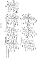
Fig. 10(a) to Fig. 10 (g) are explanatory diagrams of changes in a meshing state of outer teeth and inner teeth of the joint halves shown inFig. 7 andFig. 8 : -
Fig. 11 is a front view of a rotary shaft coupling to which a spring is attached, according to a fourth embodiment of the present invention; -
Fig. 12 is a diagram of a rotary shaft coupling to which a spring is attached, according to another embodiment of the present invention, the diagram being similar toFig. 11 ; -
Fig. 13 is diagrams of a rotary shaft coupling to which a rubber cover is attached, according to a fifth embodiment, in which (a) is a cross-sectional view in a concentric state, (b) is a cross-sectional view in an angular misalignment state, and (c) is a cross-sectional view in an axial misalignment state; -
Fig. 14 is a diagram of a rotary shaft coupling to which an O-ring is attached, according to another embodiment, the diagram being similar toFig. 13 ; and -
Fig. 15 is a cross-sectional view of a state in which the rotary shaft coupling of the present invention is applied. - Embodiments of a rotary shaft coupling of the present invention will be described in detail, below, with reference to
Fig. 1 to Fig. 15 . -
Fig. 1 to Fig. 4 are diagrams of a rotary shaft coupling according to a first embodiment of the present invention. - As shown in the diagrams, a
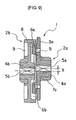
rotary shaft coupling 1 according to the first embodiment includes a pair of joint halves, ajoint half 2a and ajoint half 2b, that are respectively attached to ends of opposing rotation axis 11a androtation axis 11b. The pair ofjoint halves rotary shaft coupling 1 is formed having a gear with eight teeth. - Specifically, in the
joint half 2a, aboss section 4a is formed in a center of a disc-shapedmain body 3a. Acenter hole 5a having a rectangular cross-section is formed on theboss section 4a. Thecenter hole 5a fits with anaxial end section 12a of a rotation axis 11a in a serrated manner. Theaxial end section 12a has a rectangular cross-section. In thejoint half 2b, aboss section 4b is formed in a center of a disc-shapedmain body 3b. Acenter hole 5b having a rectangular cross-section is formed on theboss section 4b. Thecenter hole 5b fits with anaxial end section 12b of arotation axis 11b in a serrated manner. Theaxial end section 12b has a rectangular cross-section.Outer teeth 6a of a gear having eight teeth are provided on one surface of opposing surfaces of themain body 3a of thejoint half 2a and themain body 3b of thejoint half 3b.Inner teeth 6b of a gear having the same number of teeth as theouter teeth 6a are provided on the other surface. Theinner teeth 6b mesh with theouter teeth 6a. Theouter teeth 6a and theinner teeth 6b each have an involuted tooth profile of a same module. Theouter teeth 6a and theinner teeth 6b are formed such that a tooth flank of the involuted tooth profile is displaced in either one of a tangential line direction and a radial direction, or both. Here, displacement in the radial direction is also referred to as a vertical displacement. The teeth are cut and formed by a rack cutter that performs gear cutting displacing an axis of the gear further in the radial direction from a prescribed depth. Displacement in the tangential line direction is also referred to as a horizontal displacement. The teeth are cut and formed by the rack cutter that performs gear cutting being displaced in a line direction of a cutter center line. As a result, theouter teeth 6a and theinner teeth 6b can be formed such that misalignment of shaft cores of both rotation axis 11a androtation axis 11b is absorbed and rotation transmission is performed. The misalignment of the shaft core described herein refers to one of an axial misalignment x in the radial direction of the axial centers of both rotation axis 11a androtation axis 11b and an angular misalignment θ in a relative angular direction of the axial centers of both rotation axis 11a androtation axis 11b, or both, as shown inFig. 2 . Theouter teeth 6a and theinner teeth 6b are formed such that rotation transmission can be performed without rotation unevenness by bothouter teeth 6a andinner teeth 6b always favorably meshing with certainty, with a mutual contact ratio of one or more. Moreover, rotation transmission torque can be increased. As shown inFig. 3 andFig. 4 , eightreinforcement ribs 7a are formed on an outer circumferential surface of theboss section 4a at positions having the same phase as theouter teeth 6a. Eightreinforcement ribs 7b are formed on an outer circumferential surface of theboss section 4b at positions having the same phase as theinner teeth 6b. Theouter teeth 6a and theinner teeth 6b can be integrally formed using resin. The resin is merely required to have superior moldability and rigidity. For example, the resin preferably has characteristics that support stress, slidability, abrasion-resistance, durability, thermal environment, usage frequency, and the like required based on where theouter teeth 6a and theinner teeth 6b are attached on therotary shaft coupling 1. -
Fig. 5 andFig. 6 show a gear form having eight teeth according to another embodiment (second embodiment). An outer circumferential section of theinner teeth 6b is connected by a cylindricalouter cover 8, thereby reinforcing strength.Lightening cuts 9 are formed on opposite sides of theouter teeth 6a and theinner teeth 6b to reduce weight and improve dimensional accuracy. Other configurations are similar to that according to the first embodiment shown inFig. 1 . -
Fig. 7 andFig. 8 show a gear form having six teeth according to another embodiment (third embodiment). Theouter teeth 6a are formed connected to theboss section 4a and projecting from themain body 3a. Theinner teeth 6b are formed by lightening cuts being made on themain body 3b from theboss section 4b section.Several lightening cuts 9 are also formed in required areas. Other configurations are similar to that according to the embodiment shown inFig. 5 andFig. 6 . - Next, operations according to the embodiment will be described.
- A meshing state between the
outer teeth 6a and theinner teeth 6b will be described with reference toFig. 9 andFig. 10 showing therotary shaft coupling 1 having a six-tooth gear form (third embodiment). Thejoint half 2a and thejoint half 2b of therotary shaft coupling 1 according to the embodiment (third embodiment) in which the gear form has six teeth mesh and transmit rotation as shown inFig. 9. Fig. 9 shows a state in which an axial misalignment x occurs between theouter teeth 6a and theinner teeth 6b. -
Fig. 10 shows a state in which an axial misalignment x occurs between a center ca of theouter teeth 6a and a center cb of theinner teeth 6b over time (a to g inFig. 10 ), when theinner teeth 6b rotates in a counter-clockwise direction and transmits the rotation to theouter teeth 6a. - In an initial phase of rotation in
Fig. 10 (a) , theouter teeth 6a and theinner teeth 6b mesh in two pairs: a pair including an outer tooth 6aa and an inner tooth 6ba (lower left) and a pair including an outer tooth 6ab and an inner tooth 6bb (upper left). Although, as the rotation progresses, the pair including the outer tooth 6aa and the inner tooth 6ba, and the pair including the outer tooth 6ab and the inner tooth 6bb still mesh inFig. 10(b) , when the rotation further progresses in the counter-clockwise direction, the pair including the outer tooth 6aa and the inner tooth 6ba separate, as shown inFig. 10(c) . Two pairs, the pair including the outer tooth 6ab and the inner tooth 6bb, and a pair including an outer tooth 6ac and an inner tooth 6bc on a rotational direction downstream side, mesh. Subsequently, the rotation progresses to a phase shown inFig. 10(a) , while the pair including the outer tooth 6ab and the inner tooth 6bb and the pair including the outer tooth 6ac and the inner tooth 6bc remain meshing fromFig. 10(c) to Fig. 10(g) . Subsequent rotations are performed in a similar manner. When an angular misalignment θ is present, the rotation is transmitted in a similar manner as when the axial misalignment x is present inFig. 10 . When theinner teeth 6b rotate in the clockwise direction, the rotation is appropriately transmitted in a similar manner. Moreover, theouter teeth 6a can be the driving side and theinner teeth 6b can be the driven side. - As described above, in the
rotary shaft coupling 1 according to the embodiment, theouter teeth 6a and theinner teeth 6b each have an involuted tooth profile of the same module. Theouter teeth 6a and theinner teeth 6b are formed such that the tooth flank of the involuted tooth profile is displaced in either one of the tangential line direction and the radial direction, or both. Therefore, the rotation can be transmitted with rotational transmission error by theouter teeth 6a and theinner teeth 6b theoretically at zero. Theouter teeth 6a and theinner teeth 6b always favorably mesh. As a result, even when the shaft core misalignment occurs between the rotation axis 11a and therotation axis 11b, the rotation of one rotation axis 11a can be accurately transmitted to theother rotation axis 11b. Noise does not occur, and durability is increased. - Moreover, because the meshing ratio of the
outer teeth 6a and theinner teeth 6b is one or more, theouter teeth 6a and theinner teeth 6b always favorably mesh with more certainty. As a result, rotation transmission can be performed without rotation unevenness. Rotation transmission torque can also be increased. - To perform a smooth rotation transmission while maintaining strength of the
outer teeth 6a and theinner teeth 6b, the number of teeth of theouter teeth 6a and theinner teeth 6b can be six teeth to eight teeth. - To more appropriately perform a smooth rotation transmission when an angular misalignment is present, crowning can be performed on the involuted tooth profile. Alternatively, a circular-arc gear or a tapered gear form can be used.
- As shown in
Fig. 11 and Fig. 12 , according to a fourth embodiment, an arc-shapedspring 13 can be mounted between apin 14a and a pin 14b to allow theouter teeth 6a of thejoint half 2a and theinner teeth 6b of thejoint half 2b of therotary shaft coupling 1 to always mesh. Thepin 14a projects from themain body 3a of thejoint half 2a. The pin 14b projects from themain body 3b of thejoint half 2b. A force rotating themain body 3a and themain body 3b in mutually opposite directions is applied by elasticity of thespring 13. As a result, theouter teeth 6a and theinner teeth 6b always mesh at tooth flanks on one side in the circumferential direction. - In
Fig. 13 , as a fifth embodiment, arubber cover 15 having a flat cross-section is attached to outer circumferential sections of themain body 3a of thejoint half 2a and themain body 3b of thejoint half 2b of therotary shaft coupling 1. Therubber cover 15 serves as a type of ring-shaped elastic component. When the rotation axis 11a and therotation axis 11b are in a concentric state shown inFig. 13(a) , an angular misalignment state shown inFig. 13(b) , and an axial misalignment state shown inFig. 13(c) , therubber cover 15 elastically deforms and covers the outer circumferential sections of themain body 3a and themain body 3b. Moreover, because of elasticity of therubber cover 15 that works in the circumferential direction, movement that rotates themain body 3a and themain body 3b in mutually opposite directions can be prevented. As a result, theouter teeth 6a and theinner teeth 6b always mesh at the tooth flanks on one side in the circumferential direction. Moreover, therubber cover 15 seals the outer circumferential sections of themain body 3a and themain body 3b, forming an air-tight space. Therefore, dust-control of theouter teeth 6a section and theinner teeth 6b section can be achieved. Noise can be blocked, and sound-proofing can be achieved. Furthermore, the air-tight space can be filled with grease (not shown), thereby making rotation transmission smoother and preventing wear in theouter teeth 6a and theinner teeth 6b. Therubber cover 15 can prevent the grease from spattering. - As shown in
Fig. 14 , according to a sixth embodiment, a rubber O-ring 16 can be attached to the outer circumferential sections of themain body 3a and themain body 3b instead of therubber cover 15. When the O-ring 16 is used, a commercially-available, general-purpose O-ring can be used, thereby lowering costs. - Moreover, as shown in
Fig. 14 , spherical tip sections of opposing sections of theboss section 4a of thejoint half 2a and theboss section 4b of thejoint half 2b can be formed into a pouch-like shape, allowing the spherical tip surfaces to come into contact with each other. As a result, noise caused by contact between thejoint half 2a and thejoint half 2b can be effectively prevented. - In the
rotary shaft coupling 1 according to the embodiment, rotation can be very successfully transmitted even when the shaft core misalignment occurs between the rotation axis 11a and therotation axis 11b. Therefore, a number of conventional rotary shaft couplings can be reduced and an overall configuration of a rotation transmitting system can be made more compact. In therotary shaft coupling 1 according to the embodiment, as shown inFig. 15 , anoutput axis 21a, anoutput axis 22a, and anoutput axis 23a can each be directly connected between amotor 21 and agear box 22 and between thegear box 22 and agear box 23 by a singlerotary shaft coupling 1. Therefore, a number of conventional rotary shaft couplings 25 can be reduced and an overall configuration of a rotation transmitting system can be made more compact. - The present invention is not limited to the above-described embodiments. Various modifications can be made as required.
Claims (8)
- A rotary shaft coupling including a pair of joint halves that are respectively attached to opposing axial end sections and transmit rotation of one axis to another axis, the rotary shaft coupling wherein:outer teeth of a gear are provided on one joint half, and inner teeth that mesh with the outer teeth and have a same number of teeth as the outer teeth are provided on the other joint half, andthe outer teeth and the inner teeth are formed to absorb shaft core misalignment between both axes and perform rotation transmission by having an involuted tooth profile of a same module and a tooth flank of the involuted tooth profile displaced in either one of a tangential line direction and a radial direction, or both.
- The rotary shaft coupling according to claim 1, wherein the shaft core misalignment is one of an axial misalignment in a parallel direction of axial centers of both axes and angular misalignment in a relative angular direction of the axial centers of both axes, or both.
- The rotary shaft coupling according to claim 1 or 2, wherein a meshing ratio between the outer teeth and the inner teeth is one or more.
- The rotary shaft coupling according to any one of claims 1 to 3, wherein a number of teeth of the outer teeth and the inner teeth are six teeth to eight teeth.
- The rotary shaft coupling according to any one of claims 1 to 4, wherein a spring is attached that applied elastic force rotating the both joint halves in opposite directions.
- The rotary shaft coupling according to any one of claims 1 to 4, wherein a ring-shaped elastic body is attached to outer circumferential surfaces of the outer teeth and the inner teeth.
- The rotary shaft coupling according to claim 6, wherein the ring-shaped elastic body is a rubber cover sealing an outer circumferential section of a meshing section of the pair of joint halves or an O-ring.
- The rotary shaft coupling according to claim 7, wherein an air-tight space formed on an inner side of the rubber cover is filled with grease.
Applications Claiming Priority (1)
| Application Number | Priority Date | Filing Date | Title |
|---|---|---|---|
| JP2007262439A JP2009092121A (en) | 2007-10-05 | 2007-10-05 | Rotary shaft coupling |
Publications (2)
| Publication Number | Publication Date |
|---|---|
| EP2048393A2 true EP2048393A2 (en) | 2009-04-15 |
| EP2048393A3 EP2048393A3 (en) | 2010-05-19 |
Family
ID=40174778
Family Applications (1)
| Application Number | Title | Priority Date | Filing Date |
|---|---|---|---|
| EP08164697A Withdrawn EP2048393A3 (en) | 2007-10-05 | 2008-09-19 | "Rotary shaft coupling" |
Country Status (4)
| Country | Link |
|---|---|
| US (1) | US20090093317A1 (en) |
| EP (1) | EP2048393A3 (en) |
| JP (1) | JP2009092121A (en) |
| CN (1) | CN101403418A (en) |
Cited By (3)
| Publication number | Priority date | Publication date | Assignee | Title |
|---|---|---|---|---|
| GB2509560A (en) * | 2013-01-07 | 2014-07-09 | Romax Technology Ltd | A power transmission connector suitable for a turbine main shaft and planet carrier |
| ES2507290A1 (en) * | 2013-04-11 | 2014-10-14 | Product & Process Development, S. L. | Automatic gear-changing system for vehicles having an internal combustion engine |
| EP2711782A3 (en) * | 2012-09-25 | 2017-03-15 | Kyocera Document Solutions Inc. | Image forming apparatus, toner case and drive transmission mechanism |
Families Citing this family (66)
| Publication number | Priority date | Publication date | Assignee | Title |
|---|---|---|---|---|
| WO2010124407A1 (en) * | 2009-04-28 | 2010-11-04 | Ma Yinan | Connection assembly of multi-purpose gardening machine and gardening machine provided with the connection assembly |
| JP5272935B2 (en) * | 2009-07-09 | 2013-08-28 | 村田機械株式会社 | Coupling device |
| US20110311303A1 (en) * | 2010-06-18 | 2011-12-22 | Kenneth Damon Black | Method and apparatus for rotor torque transmission |
| CN102376487A (en) * | 2010-08-11 | 2012-03-14 | 西安煤矿机械有限公司 | Highly reliable isolation switch for coal cutter |
| CN102380460A (en) * | 2010-09-03 | 2012-03-21 | 上海安亭科学仪器厂 | Shaft enclosing device for protecting spindle |
| CN102594091A (en) * | 2011-01-05 | 2012-07-18 | 鸿富锦精密工业(深圳)有限公司 | Shaft transmission mechanism |
| US11708752B2 (en) | 2011-04-07 | 2023-07-25 | Typhon Technology Solutions (U.S.), Llc | Multiple generator mobile electric powered fracturing system |
| US11255173B2 (en) | 2011-04-07 | 2022-02-22 | Typhon Technology Solutions, Llc | Mobile, modular, electrically powered system for use in fracturing underground formations using liquid petroleum gas |
| US9140110B2 (en) | 2012-10-05 | 2015-09-22 | Evolution Well Services, Llc | Mobile, modular, electrically powered system for use in fracturing underground formations using liquid petroleum gas |
| US10495153B2 (en) * | 2011-08-30 | 2019-12-03 | Rad Technologies Inc. | Power take-off coupler counteracting axial load and equipment equipped therewith |
| CN102517765A (en) * | 2011-10-28 | 2012-06-27 | 吴江市合欣转移印花有限公司 | Coupling of shuttle loom |
| CN102661645B (en) * | 2012-05-14 | 2014-08-13 | 湖北美的电冰箱有限公司 | Refrigerator, ice storage box and ice outlet connecting piece |
| US10526882B2 (en) | 2012-11-16 | 2020-01-07 | U.S. Well Services, LLC | Modular remote power generation and transmission for hydraulic fracturing system |
| US9745840B2 (en) | 2012-11-16 | 2017-08-29 | Us Well Services Llc | Electric powered pump down |
| US11476781B2 (en) | 2012-11-16 | 2022-10-18 | U.S. Well Services, LLC | Wireline power supply during electric powered fracturing operations |
| US11449018B2 (en) | 2012-11-16 | 2022-09-20 | U.S. Well Services, LLC | System and method for parallel power and blackout protection for electric powered hydraulic fracturing |
| US9995218B2 (en) | 2012-11-16 | 2018-06-12 | U.S. Well Services, LLC | Turbine chilling for oil field power generation |
| US10119381B2 (en) | 2012-11-16 | 2018-11-06 | U.S. Well Services, LLC | System for reducing vibrations in a pressure pumping fleet |
| US9893500B2 (en) | 2012-11-16 | 2018-02-13 | U.S. Well Services, LLC | Switchgear load sharing for oil field equipment |
| US9650879B2 (en) | 2012-11-16 | 2017-05-16 | Us Well Services Llc | Torsional coupling for electric hydraulic fracturing fluid pumps |
| US10036238B2 (en) | 2012-11-16 | 2018-07-31 | U.S. Well Services, LLC | Cable management of electric powered hydraulic fracturing pump unit |
| US9970278B2 (en) | 2012-11-16 | 2018-05-15 | U.S. Well Services, LLC | System for centralized monitoring and control of electric powered hydraulic fracturing fleet |
| US10407990B2 (en) | 2012-11-16 | 2019-09-10 | U.S. Well Services, LLC | Slide out pump stand for hydraulic fracturing equipment |
| US10232332B2 (en) | 2012-11-16 | 2019-03-19 | U.S. Well Services, Inc. | Independent control of auger and hopper assembly in electric blender system |
| US9840901B2 (en) | 2012-11-16 | 2017-12-12 | U.S. Well Services, LLC | Remote monitoring for hydraulic fracturing equipment |
| US10020711B2 (en) | 2012-11-16 | 2018-07-10 | U.S. Well Services, LLC | System for fueling electric powered hydraulic fracturing equipment with multiple fuel sources |
| US10254732B2 (en) | 2012-11-16 | 2019-04-09 | U.S. Well Services, Inc. | Monitoring and control of proppant storage from a datavan |
| US9410410B2 (en) | 2012-11-16 | 2016-08-09 | Us Well Services Llc | System for pumping hydraulic fracturing fluid using electric pumps |
| US11959371B2 (en) | 2012-11-16 | 2024-04-16 | Us Well Services, Llc | Suction and discharge lines for a dual hydraulic fracturing unit |
| CN103047306B (en) * | 2012-12-28 | 2015-06-03 | 广东威创视讯科技股份有限公司 | Elastic connecting device |
| US9222523B2 (en) * | 2013-07-09 | 2015-12-29 | Solarcity, Inc. | Dual-mode torque transfer in laterally engaging drive couplers exhibiting axial misalignment with driven couplers |
| US9982722B2 (en) | 2013-07-09 | 2018-05-29 | Solarcity Corporation | Torque transfer in laterally engaging drive couplers exhibiting axial misalignment with driven couplers |
| WO2015146324A1 (en) * | 2014-03-25 | 2015-10-01 | 京セラドキュメントソリューションズ株式会社 | Drive transmission device and image formation device |
| CA2908276C (en) | 2014-10-14 | 2022-11-01 | Us Well Services Llc | Parallel power and blackout protection for electric hydraulic fracturing |
| CN105370483A (en) * | 2015-06-15 | 2016-03-02 | 河海大学 | Wide-width low-water-head water flow power generation flexible system |
| WO2017066946A1 (en) | 2015-10-21 | 2017-04-27 | 深圳市大疆创新科技有限公司 | Transmission structure, follow focus, execution end of the follow focus, and imaging apparatus |
| US12078110B2 (en) | 2015-11-20 | 2024-09-03 | Us Well Services, Llc | System for gas compression on electric hydraulic fracturing fleets |
| US12027831B2 (en) | 2016-04-15 | 2024-07-02 | U.S. Well Services, LLC | Switchgear load sharing for oil field equipment |
| CN107813864B (en) * | 2016-09-13 | 2020-05-22 | 株式会社万都 | Power transmission components for electric power steering systems |
| DE102016222772B3 (en) * | 2016-11-18 | 2018-04-26 | Schaeffler Technologies AG & Co. KG | Flexible coupling |
| US11181107B2 (en) | 2016-12-02 | 2021-11-23 | U.S. Well Services, LLC | Constant voltage power distribution system for use with an electric hydraulic fracturing system |
| CN107097867B (en) * | 2017-03-06 | 2019-03-22 | 浙江大学 | A flexible connector and a robot foot structure using the same |
| US10280724B2 (en) | 2017-07-07 | 2019-05-07 | U.S. Well Services, Inc. | Hydraulic fracturing equipment with non-hydraulic power |
| DE102017212060B4 (en) * | 2017-07-14 | 2024-07-18 | Bayerische Motoren Werke Aktiengesellschaft | Coupling device |
| US11067481B2 (en) | 2017-10-05 | 2021-07-20 | U.S. Well Services, LLC | Instrumented fracturing slurry flow system and method |
| CA3078879A1 (en) | 2017-10-13 | 2019-04-18 | U.S. Well Services, LLC | Automated fracturing system and method |
| AR114805A1 (en) | 2017-10-25 | 2020-10-21 | U S Well Services Llc | INTELLIGENT FRACTURING METHOD AND SYSTEM |
| WO2019113147A1 (en) | 2017-12-05 | 2019-06-13 | U.S. Well Services, Inc. | Multi-plunger pumps and associated drive systems |
| WO2019113153A1 (en) | 2017-12-05 | 2019-06-13 | U.S. Well Services, Inc. | High horsepower pumping configuration for an electric hydraulic fracturing system |
| AR114091A1 (en) | 2018-02-05 | 2020-07-22 | Us Well Services Inc | ELECTRICAL CHARGE MANAGEMENT IN MICROGRID |
| CA3097051A1 (en) | 2018-04-16 | 2019-10-24 | U.S. Well Services, LLC | Hybrid hydraulic fracturing fleet |
| CA3103490A1 (en) | 2018-06-15 | 2019-12-19 | U.S. Well Services, LLC | Integrated mobile power unit for hydraulic fracturing |
| WO2020056258A1 (en) | 2018-09-14 | 2020-03-19 | U.S. Well Services, LLC | Riser assist for wellsites |
| CA3115669A1 (en) | 2018-10-09 | 2020-04-16 | U.S. Well Services, LLC | Modular switchgear system and power distribution for electric oilfield equipment |
| CN109530043A (en) * | 2018-12-18 | 2019-03-29 | 上海迎录机械设备有限公司 | Head detachable structure and the blade type pulverizer for using the structure |
| CN109780073B (en) * | 2019-03-06 | 2024-04-09 | 杭州精通汽车零部件有限公司 | Constant speed frame type universal joint fork assembly |
| US11578577B2 (en) | 2019-03-20 | 2023-02-14 | U.S. Well Services, LLC | Oversized switchgear trailer for electric hydraulic fracturing |
| WO2020231483A1 (en) | 2019-05-13 | 2020-11-19 | U.S. Well Services, LLC | Encoderless vector control for vfd in hydraulic fracturing applications |
| WO2021022048A1 (en) | 2019-08-01 | 2021-02-04 | U.S. Well Services, LLC | High capacity power storage system for electric hydraulic fracturing |
| CN110977848A (en) * | 2019-12-20 | 2020-04-10 | 薛春红 | Synchronous wrench for arranging bolts in annular array |
| US11009162B1 (en) | 2019-12-27 | 2021-05-18 | U.S. Well Services, LLC | System and method for integrated flow supply line |
| CN112658293A (en) * | 2020-12-08 | 2021-04-16 | 珠海格力电器股份有限公司 | Shaft core assembly convenient to disassemble and assemble and electric spindle |
| CN113530990A (en) * | 2021-07-14 | 2021-10-22 | 吴江市天缘纺织有限公司 | Device capable of connecting different shaft types |
| CN114412931B (en) * | 2022-01-20 | 2023-05-02 | 白城师范学院 | Accelerating mechanism for assembling fluent strips |
| CN115057277A (en) * | 2022-06-15 | 2022-09-16 | 晟通科技集团有限公司 | Rewinding equipment |
| US11955782B1 (en) | 2022-11-01 | 2024-04-09 | Typhon Technology Solutions (U.S.), Llc | System and method for fracturing of underground formations using electric grid power |
Citations (1)
| Publication number | Priority date | Publication date | Assignee | Title |
|---|---|---|---|---|
| JPH10331860A (en) | 1997-05-30 | 1998-12-15 | Kyoritsu Kogyo Kk | Plastic shaft coupling |
Family Cites Families (13)
| Publication number | Priority date | Publication date | Assignee | Title |
|---|---|---|---|---|
| US970793A (en) * | 1910-02-02 | 1910-09-20 | Carlson Motor & Truck Company | Shaft-coupling. |
| US1263252A (en) * | 1915-01-08 | 1918-04-16 | G A Schanze | Coupling device. |
| US1429980A (en) * | 1921-12-16 | 1922-09-26 | Charles M Spangler | Universal joint for coupling shafts |
| US2892327A (en) * | 1955-12-27 | 1959-06-30 | William E Kressin | Flexible coupling |
| US2943463A (en) * | 1959-11-23 | 1960-07-05 | Gen Electric | Grease seal for high speed flexible coupling |
| US3410112A (en) * | 1966-12-07 | 1968-11-12 | Lovejoy Flexible Coupling Comp | Spider for flexible coupling |
| FR2390077A7 (en) * | 1977-05-04 | 1978-12-01 | Ducellier & Cie | Ignition system distributor drive coupling - has two coaxial parts with lugs received in ring slots to be held by circlip in annular groove |
| US4927340A (en) * | 1988-08-19 | 1990-05-22 | Arthur D. Little, Inc. | Synchronizing and unloading system for scroll fluid device |
| US5051075A (en) * | 1990-02-20 | 1991-09-24 | Arthur D. Little, Inc. | Gearing system having interdigited teeth with convex and concave surface portions |
| US5149255A (en) * | 1990-02-20 | 1992-09-22 | Arthur D. Little, Inc. | Gearing system having interdigital concave-convex teeth formed as invalutes or multi-faceted polygons |
| JPH07286622A (en) * | 1994-04-15 | 1995-10-31 | Mitsubishi Electric Corp | Flexible gear coupling |
| US5730657A (en) * | 1997-03-20 | 1998-03-24 | General Motors Corporation | Shaft coupling |
| FR2836966B1 (en) * | 2002-03-07 | 2004-12-10 | Peugeot Citroen Automobiles Sa | DEVICE FOR COUPLING TWO SHAFTS AND VEHICLE COMPRISING SUCH A DEVICE |
-
2007
- 2007-10-05 JP JP2007262439A patent/JP2009092121A/en active Pending
-
2008
- 2008-09-19 EP EP08164697A patent/EP2048393A3/en not_active Withdrawn
- 2008-09-23 US US12/284,506 patent/US20090093317A1/en not_active Abandoned
- 2008-09-26 CN CNA2008101663868A patent/CN101403418A/en active Pending
Patent Citations (1)
| Publication number | Priority date | Publication date | Assignee | Title |
|---|---|---|---|---|
| JPH10331860A (en) | 1997-05-30 | 1998-12-15 | Kyoritsu Kogyo Kk | Plastic shaft coupling |
Cited By (4)
| Publication number | Priority date | Publication date | Assignee | Title |
|---|---|---|---|---|
| EP2711782A3 (en) * | 2012-09-25 | 2017-03-15 | Kyocera Document Solutions Inc. | Image forming apparatus, toner case and drive transmission mechanism |
| GB2509560A (en) * | 2013-01-07 | 2014-07-09 | Romax Technology Ltd | A power transmission connector suitable for a turbine main shaft and planet carrier |
| ES2507290A1 (en) * | 2013-04-11 | 2014-10-14 | Product & Process Development, S. L. | Automatic gear-changing system for vehicles having an internal combustion engine |
| WO2014167164A1 (en) * | 2013-04-11 | 2014-10-16 | Product & Process Development, S. L. | Automatic gear-changing system for vehicles having an internal combustion engine |
Also Published As
| Publication number | Publication date |
|---|---|
| EP2048393A3 (en) | 2010-05-19 |
| CN101403418A (en) | 2009-04-08 |
| JP2009092121A (en) | 2009-04-30 |
| US20090093317A1 (en) | 2009-04-09 |
Similar Documents
| Publication | Publication Date | Title |
|---|---|---|
| US20090093317A1 (en) | Rotary shaft coupling | |
| EP2759743B1 (en) | Speed reducer | |
| JP6149381B2 (en) | Torque transmission joint and electric power steering device | |
| CN107429752B (en) | Joints and worm gear reducers for torque transmission | |
| EP2813724A1 (en) | Rotation transmitting member, coupling directly connected to shafts, and shaft connecting mechanism | |
| JP5309997B2 (en) | Electric power steering device | |
| WO2003006301A1 (en) | Electronic control power steering device | |
| JP2013167350A (en) | Joint for torque transmission and electric power steering device | |
| JP5157666B2 (en) | Elastic shaft coupling and electric power steering device | |
| JP2008215549A (en) | GEAR GEAR, GEAR GEAR MANUFACTURING METHOD, AND GEARED MOTOR | |
| CN110494665B (en) | Torque transmission joint and electric power steering device | |
| KR20120078847A (en) | Power transmitting motor coupling device | |
| KR101961697B1 (en) | Power transmission gear unit and automobile running board drive actuator unit including the gear unit | |
| US11320037B2 (en) | Speed reducer | |
| JP5942569B2 (en) | Torque transmission joint and electric power steering device | |
| JP6102616B2 (en) | Torque transmission joint and electric power steering device | |
| KR102605287B1 (en) | Reduction device using eccentric shaft and rolling contact | |
| WO2019022015A1 (en) | Torque transmission joint and electric power steering device | |
| JP2004036823A (en) | Oldham's coupling | |
| JP6951265B2 (en) | Gear device | |
| EP1715206A1 (en) | Constant velocity universal joint | |
| JP3825625B2 (en) | Vehicle shaft coupling | |
| JP2018053939A (en) | Spline telescopic shaft | |
| JP2020153432A (en) | Vehicle power transmission mechanism | |
| KR102177597B1 (en) | Constant velocity joint |
Legal Events
| Date | Code | Title | Description |
|---|---|---|---|
| PUAI | Public reference made under article 153(3) epc to a published international application that has entered the european phase |
Free format text: ORIGINAL CODE: 0009012 |
|
| AK | Designated contracting states |
Kind code of ref document: A2 Designated state(s): AT BE BG CH CY CZ DE DK EE ES FI FR GB GR HR HU IE IS IT LI LT LU LV MC MT NL NO PL PT RO SE SI SK TR |
|
| AX | Request for extension of the european patent |
Extension state: AL BA MK RS |
|
| PUAL | Search report despatched |
Free format text: ORIGINAL CODE: 0009013 |
|
| AK | Designated contracting states |
Kind code of ref document: A3 Designated state(s): AT BE BG CH CY CZ DE DK EE ES FI FR GB GR HR HU IE IS IT LI LT LU LV MC MT NL NO PL PT RO SE SI SK TR |
|
| AX | Request for extension of the european patent |
Extension state: AL BA MK RS |
|
| AKY | No designation fees paid | ||
| REG | Reference to a national code |
Ref country code: DE Ref legal event code: 8566 |
|
| STAA | Information on the status of an ep patent application or granted ep patent |
Free format text: STATUS: THE APPLICATION IS DEEMED TO BE WITHDRAWN |
|
| 18D | Application deemed to be withdrawn |
Effective date: 20101221 |