EP2048328A2 - Seal assembly retention feature and assembly method - Google Patents
Seal assembly retention feature and assembly method Download PDFInfo
- Publication number
- EP2048328A2 EP2048328A2 EP08252654A EP08252654A EP2048328A2 EP 2048328 A2 EP2048328 A2 EP 2048328A2 EP 08252654 A EP08252654 A EP 08252654A EP 08252654 A EP08252654 A EP 08252654A EP 2048328 A2 EP2048328 A2 EP 2048328A2
- Authority
- EP
- European Patent Office
- Prior art keywords
- seal
- channel
- tab
- slot
- component
- Prior art date
- Legal status (The legal status is an assumption and is not a legal conclusion. Google has not performed a legal analysis and makes no representation as to the accuracy of the status listed.)
- Granted
Links
Images


Classifications
-
- F—MECHANICAL ENGINEERING; LIGHTING; HEATING; WEAPONS; BLASTING
- F16—ENGINEERING ELEMENTS AND UNITS; GENERAL MEASURES FOR PRODUCING AND MAINTAINING EFFECTIVE FUNCTIONING OF MACHINES OR INSTALLATIONS; THERMAL INSULATION IN GENERAL
- F16J—PISTONS; CYLINDERS; SEALINGS
- F16J15/00—Sealings
- F16J15/02—Sealings between relatively-stationary surfaces
- F16J15/06—Sealings between relatively-stationary surfaces with solid packing compressed between sealing surfaces
- F16J15/08—Sealings between relatively-stationary surfaces with solid packing compressed between sealing surfaces with exclusively metal packing
- F16J15/0887—Sealings between relatively-stationary surfaces with solid packing compressed between sealing surfaces with exclusively metal packing the sealing effect being obtained by elastic deformation of the packing
-
- F—MECHANICAL ENGINEERING; LIGHTING; HEATING; WEAPONS; BLASTING
- F01—MACHINES OR ENGINES IN GENERAL; ENGINE PLANTS IN GENERAL; STEAM ENGINES
- F01D—NON-POSITIVE DISPLACEMENT MACHINES OR ENGINES, e.g. STEAM TURBINES
- F01D11/00—Preventing or minimising internal leakage of working-fluid, e.g. between stages
- F01D11/005—Sealing means between non relatively rotating elements
-
- F—MECHANICAL ENGINEERING; LIGHTING; HEATING; WEAPONS; BLASTING
- F01—MACHINES OR ENGINES IN GENERAL; ENGINE PLANTS IN GENERAL; STEAM ENGINES
- F01D—NON-POSITIVE DISPLACEMENT MACHINES OR ENGINES, e.g. STEAM TURBINES
- F01D11/00—Preventing or minimising internal leakage of working-fluid, e.g. between stages
- F01D11/005—Sealing means between non relatively rotating elements
- F01D11/006—Sealing the gap between rotor blades or blades and rotor
- F01D11/008—Sealing the gap between rotor blades or blades and rotor by spacer elements between the blades, e.g. independent interblade platforms
-
- F—MECHANICAL ENGINEERING; LIGHTING; HEATING; WEAPONS; BLASTING
- F01—MACHINES OR ENGINES IN GENERAL; ENGINE PLANTS IN GENERAL; STEAM ENGINES
- F01D—NON-POSITIVE DISPLACEMENT MACHINES OR ENGINES, e.g. STEAM TURBINES
- F01D9/00—Stators
- F01D9/02—Nozzles; Nozzle boxes; Stator blades; Guide conduits, e.g. individual nozzles
- F01D9/04—Nozzles; Nozzle boxes; Stator blades; Guide conduits, e.g. individual nozzles forming ring or sector
- F01D9/041—Nozzles; Nozzle boxes; Stator blades; Guide conduits, e.g. individual nozzles forming ring or sector using blades
-
- F—MECHANICAL ENGINEERING; LIGHTING; HEATING; WEAPONS; BLASTING
- F02—COMBUSTION ENGINES; HOT-GAS OR COMBUSTION-PRODUCT ENGINE PLANTS
- F02C—GAS-TURBINE PLANTS; AIR INTAKES FOR JET-PROPULSION PLANTS; CONTROLLING FUEL SUPPLY IN AIR-BREATHING JET-PROPULSION PLANTS
- F02C7/00—Features, components parts, details or accessories, not provided for in, or of interest apart form groups F02C1/00 - F02C6/00; Air intakes for jet-propulsion plants
- F02C7/28—Arrangement of seals
-
- F—MECHANICAL ENGINEERING; LIGHTING; HEATING; WEAPONS; BLASTING
- F05—INDEXING SCHEMES RELATING TO ENGINES OR PUMPS IN VARIOUS SUBCLASSES OF CLASSES F01-F04
- F05D—INDEXING SCHEME FOR ASPECTS RELATING TO NON-POSITIVE-DISPLACEMENT MACHINES OR ENGINES, GAS-TURBINES OR JET-PROPULSION PLANTS
- F05D2240/00—Components
- F05D2240/80—Platforms for stationary or moving blades
-
- Y—GENERAL TAGGING OF NEW TECHNOLOGICAL DEVELOPMENTS; GENERAL TAGGING OF CROSS-SECTIONAL TECHNOLOGIES SPANNING OVER SEVERAL SECTIONS OF THE IPC; TECHNICAL SUBJECTS COVERED BY FORMER USPC CROSS-REFERENCE ART COLLECTIONS [XRACs] AND DIGESTS
- Y02—TECHNOLOGIES OR APPLICATIONS FOR MITIGATION OR ADAPTATION AGAINST CLIMATE CHANGE
- Y02T—CLIMATE CHANGE MITIGATION TECHNOLOGIES RELATED TO TRANSPORTATION
- Y02T50/00—Aeronautics or air transport
- Y02T50/60—Efficient propulsion technologies, e.g. for aircraft
-
- Y—GENERAL TAGGING OF NEW TECHNOLOGICAL DEVELOPMENTS; GENERAL TAGGING OF CROSS-SECTIONAL TECHNOLOGIES SPANNING OVER SEVERAL SECTIONS OF THE IPC; TECHNICAL SUBJECTS COVERED BY FORMER USPC CROSS-REFERENCE ART COLLECTIONS [XRACs] AND DIGESTS
- Y10—TECHNICAL SUBJECTS COVERED BY FORMER USPC
- Y10T—TECHNICAL SUBJECTS COVERED BY FORMER US CLASSIFICATION
- Y10T29/00—Metal working
- Y10T29/49—Method of mechanical manufacture
- Y10T29/49229—Prime mover or fluid pump making
- Y10T29/49297—Seal or packing making
-
- Y—GENERAL TAGGING OF NEW TECHNOLOGICAL DEVELOPMENTS; GENERAL TAGGING OF CROSS-SECTIONAL TECHNOLOGIES SPANNING OVER SEVERAL SECTIONS OF THE IPC; TECHNICAL SUBJECTS COVERED BY FORMER USPC CROSS-REFERENCE ART COLLECTIONS [XRACs] AND DIGESTS
- Y10—TECHNICAL SUBJECTS COVERED BY FORMER USPC
- Y10T—TECHNICAL SUBJECTS COVERED BY FORMER US CLASSIFICATION
- Y10T29/00—Metal working
- Y10T29/49—Method of mechanical manufacture
- Y10T29/49316—Impeller making
- Y10T29/4932—Turbomachine making
- Y10T29/49321—Assembling individual fluid flow interacting members, e.g., blades, vanes, buckets, on rotary support member
-
- Y—GENERAL TAGGING OF NEW TECHNOLOGICAL DEVELOPMENTS; GENERAL TAGGING OF CROSS-SECTIONAL TECHNOLOGIES SPANNING OVER SEVERAL SECTIONS OF THE IPC; TECHNICAL SUBJECTS COVERED BY FORMER USPC CROSS-REFERENCE ART COLLECTIONS [XRACs] AND DIGESTS
- Y10—TECHNICAL SUBJECTS COVERED BY FORMER USPC
- Y10T—TECHNICAL SUBJECTS COVERED BY FORMER US CLASSIFICATION
- Y10T29/00—Metal working
- Y10T29/49—Method of mechanical manufacture
- Y10T29/49826—Assembling or joining
- Y10T29/49908—Joining by deforming
- Y10T29/49915—Overedge assembling of seated part
- Y10T29/49922—Overedge assembling of seated part by bending over projecting prongs
Definitions
- This invention relates to seals and, more particularly, to a component having a retention feature for limiting movement of a feather seal.
- Feather seals are commonly known and used in aerospace and other industries to provide a seal between two adjacent components.
- gas turbine engine vanes are arranged in a circumferential configuration to form a vane ring about a center axis of the engine.
- each vane includes an airfoil and a platform section. When assembled into the ring, the platforms abut and define a radially inner section for receiving hot gas flow and a radially outer surrounding section.
- the platforms include channels for receiving a feather seal that seals the radially inner section from the radially outer section.
- feather seals often provide effective sealing
- conventional feather seals may become damaged during assembly of the vanes into the vane ring.
- the vanes may be manually arranged into the vane ring configuration before assembly into the engine.
- the vane positions may be adjusted to achieve the desired vane ring alignment, which may cause the feather seals to become liberated from the channels or cause the feather seals to move within the channels. The movement may damage the seals or cause the seals to move from a desired sealing position and thereby prevent the feather seal from properly sealing.
- dimensional variation of the channels and seals may contribute to slightly oversized or undersized channels that permit seal movement or pinch the seals.
- disassembly of multiple vanes may be required if it is necessary to replace a damaged feather seal.
- An example seal assembly includes a body having two circumferential sides, a leading end, and a trailing end. At least one of the circumferential sides includes a first channel sidewall, a second channel sidewall, and a channel bottom wall that together define a seal channel for receiving a seal. At least one of the first channel sidewall, the second channel sidewall, or the channel bottom wall includes a slot for limiting movement between the seal and the seal channel.
- the seal assembly includes a first component and a second component adjacent the first component.
- the first component and the second component each include the body such that one of the circumferential sides of the first component is adjacent one of the circumferential sides of the second component.
- the circumferential sides each include a seal channel, and at least one of the seal channels includes a first channel sidewall, a second channel sidewall, and a channel bottom wall that together define the seal channel, and at least one of the first channel sidewall, the second channel sidewall, or the channel bottom wall includes a slot.
- a seal is at least partially within the seal channels.
- the seal includes a retention feature that cooperates with the slot to limit movement between the seal and the seal channels.
- an example method of limiting movement between the seal and the seal channel includes inserting the tab of the seal at least partially into the slot of the seal channel to limit movement between the seal and the seal channel.
- the disclosed examples provide a retention feature for use in turbine vanes or other segmented sealed components that limits movement of a feather seal used between the components, such as during assembly of the components.
- Figure 1 illustrates selected portions of an example gas turbine engine 10, such as a gas turbine engine 10 used for propulsion.
- the turbine engine 10 is disposed about an engine centerline 12 and includes a fan 14, a compressor section 16, a combustion section 18, and a turbine section 20.
- the combustion section 18 and the turbine section 20 include corresponding blades 22 and vanes 24.
- Blade outer air seal segments 26 are disposed circumferentially about the turbine section 20 to define a hot gas path between an outer structure of the gas turbine engine 10 and the turbine section 20.
- the segments may form a ring around the engine centerline 12.
- One non-limiting example of the blade outer air seal segments 26 can be found in United States Patent No. 5,639,210 .
- FIG. 1 is a somewhat schematic presentation for illustrative purposes only and is not a limitation on the disclosed examples. Additionally, there are various types of gas turbine engines, many of which could benefit from the examples disclosed herein, which are not limited to the design shown.
- FIG. 2 illustrates an example of one of the vanes 24 from the gas turbine engine 10.
- a plurality of the vanes 24 are arranged circumferentially about the engine center line 12 in a vane ring assembly.
- each of the vanes 24 includes an airfoil section 42 coupled with an inner platform 44 and an outer platform 46.
- the inner platform 44 is oriented near to the engine center line 12, while the outer platform 46 is oriented away from the engine center line 12.
- the inner platform 44 and the outer platform 46 may be relatively similar with respect to sealing between the vanes 24.
- the outer platform 46 will be described, although it is to be understood that the disclosed examples may also apply to the inner platform 44.
- the vane 24 is the basis of the disclosed examples, the examples are also applicable to the blades 22, the blade outer air seal segments 26, or other segmented sealed components, for example.
- the outer platform 46 includes a leading end 48 and a trailing end 50 that extend between circumferential sides 52 and 54.
- Each of the circumferential sides 52 and 54 includes a seal channel 56.
- each circumferential side 52 or 54 includes a first sidewall 60 and an opposed second sidewall 62 that are joined by a channel bottom wall 64 to define the seal channel 56.
- the outer platform 46 includes a retention feature 74 for limiting movement between the feather seal 58 and the seal channel 56.
- a retention feature 74 for limiting movement between the feather seal 58 and the seal channel 56.
- each circumferential side 52 and 54 includes one of the retention features 74.
- the circumferential sides 52 or 54 may include the retention feature, and in other examples one or both of the circumferential sides 52 and 54 may include multiple retention features 74.
- the circumferential sides of the inner platform 44 may include none, one, or multiple retention features 74.
- the retention feature 74 comprises a slot 76 for receiving a tab 78 ( Figure 7 ) that extends generally perpendicularly from a main body 79 of the feather seal 58.
- the term "perpendicular" refers to a nominal geometry, such as within a desired tolerance.
- the slot 76 and the tab 78 cooperate to limit, and in some examples prevent, circumferential movement of the feather seal 58 relative to the seal channel 56.
- the forward and trailing sides of the slot 76 abut the forward and trailing ends of the tab 78 to limit circumferential movement between the feather seal 58 and the seal channel 56.
- the slot 76 and the tab 78 may also cooperate to limit axial movement of the feather seal 58, depending on the shape of the slot 76, shape of the tab 78, or the fit between the slot 76 and the tab 78.
- the slot 76 may be any of a variety of different shapes or sizes, depending upon the desired design of the feather seal 58 or other design considerations. Further, the slot 76 may be formed in the outer platform using a suitable forming method, such as machining, casting, or other known method. In the illustrated example, the slot 76 extends entirely through the channel bottom wall 64, partially through the channel sidewall 60 and partially through the channel sidewall 62.
- the slot 76 includes a recess or step 80 relative to the channel sidewall 62.
- the step 80 provides the benefit of offsetting the bottom of the slot 76 from the channel sidewall 62 such that the feather seal 58 is in a desired seal position that is flush with the channel sidewall 62.
- the size of the step 80 is at least as great as the combined ' dimensional variation from the manufacturing of the platform 46 and the slot 76.
- casting the platform 46 may result in a dimensional variation of ⁇ X and machining the slot 76 may result in a dimensional variation of ⁇ Y for a minimum step size 77 of X + Y ( Figure 4 ).
- Designing the size of the step 80 based on the dimensional variations provides the benefit of assuring that the bottom of the slot 76 is recessed from the channel sidewall 62 such that the bottom of the slot 76 does not inhibit the feather seal 58 from sitting flush with the channel sidewall 62.
- the tab 78 of the feather seal 58 extends through the slot 76 with an adequate amount of clearance such that the tab 78 can be deformed (e.g., bent) to retain the feather seal 58 in the seal channel 56.
- Deforming the tab 78 (upwards in Figure 8 ) provides the benefit of locking the feather seal 58 relative to the seal channel 56 and also preventing axial movement of the feather seal 58.
- the tab 78 may be deformed manually and may be deformed to any desired angle.
- the feather seal 58 is thereby secured within the seal channel 56 to reduce the opportunity of damaging the feather seal 58 during assembly into a vane ring.
- the tab 78 is deformed before insertion through the slot 76 such that the tab 78 is non-planar.
- the tab 78 is compressed as it is inserted through the slot 76.
- the tab 78 decompresses because of the resilience of the material of the feather seal 58, such that the end of the tab 78 abuts a surface 81 of the channel sidewall 60 to retain the feather seal 58 within the seal channel 56.
- Figures 10 , 11, and 12 illustrate another embodiment retainer feature 74' that includes a slot 76' for retaining the feather seal 58 in a manner similar to as described above.
- the slot 76' extends entirely through the channel bottom wall 64 and entirely through the channel sidewall 60, but does not extend at all into the channel sidewall 62.
- the slot 76' receives a tab 178 of another type of feather seal 158.
- the tab 178 includes two curved sections 160a and 160b that form a serpentine shape that allows the tab 178 to extend over the step 80' and into the slot 76'.
- the forward and trailing sides of the slot 76' abut the forward and trailing ends of the tab 178 to limit circumferential movement between the feather seal 158 and the seal channel 56.
- the step 80' abuts a portion of a tab 178 to limit relative axial movement of the feather seal 158.
- FIG. 15 another embodiment feather seal 258 and tab 278 is shown.
- a plane defined by the tab 278 is offset using a curved section 282 from a plane defined by a main body section 279 of the feather seal 58.
- the curved section 282 allows the tab to extend over the step 80' and into the slot 76'.
- the tab 278 may be deformed upwards as shown in Figure 16 to further limit movement between feather seal 258 and the seal channel 56.
Landscapes
- Engineering & Computer Science (AREA)
- General Engineering & Computer Science (AREA)
- Mechanical Engineering (AREA)
- Chemical & Material Sciences (AREA)
- Combustion & Propulsion (AREA)
- Turbine Rotor Nozzle Sealing (AREA)
- Sealing Devices (AREA)
- Gasket Seals (AREA)
Abstract
Description
- This invention relates to seals and, more particularly, to a component having a retention feature for limiting movement of a feather seal.
- Feather seals are commonly known and used in aerospace and other industries to provide a seal between two adjacent components. For example, gas turbine engine vanes are arranged in a circumferential configuration to form a vane ring about a center axis of the engine. Typically, each vane includes an airfoil and a platform section. When assembled into the ring, the platforms abut and define a radially inner section for receiving hot gas flow and a radially outer surrounding section.
- Typically, the platforms include channels for receiving a feather seal that seals the radially inner section from the radially outer section. Although feather seals often provide effective sealing, conventional feather seals may become damaged during assembly of the vanes into the vane ring. For example, the vanes may be manually arranged into the vane ring configuration before assembly into the engine. During assembly, the vane positions may be adjusted to achieve the desired vane ring alignment, which may cause the feather seals to become liberated from the channels or cause the feather seals to move within the channels. The movement may damage the seals or cause the seals to move from a desired sealing position and thereby prevent the feather seal from properly sealing. Additionally, dimensional variation of the channels and seals may contribute to slightly oversized or undersized channels that permit seal movement or pinch the seals. Moreover, once the vane ring is assembled, disassembly of multiple vanes may be required if it is necessary to replace a damaged feather seal.
- An example seal assembly includes a body having two circumferential sides, a leading end, and a trailing end. At least one of the circumferential sides includes a first channel sidewall, a second channel sidewall, and a channel bottom wall that together define a seal channel for receiving a seal. At least one of the first channel sidewall, the second channel sidewall, or the channel bottom wall includes a slot for limiting movement between the seal and the seal channel.
- In one example, the seal assembly includes a first component and a second component adjacent the first component. The first component and the second component each include the body such that one of the circumferential sides of the first component is adjacent one of the circumferential sides of the second component. The circumferential sides each include a seal channel, and at least one of the seal channels includes a first channel sidewall, a second channel sidewall, and a channel bottom wall that together define the seal channel, and at least one of the first channel sidewall, the second channel sidewall, or the channel bottom wall includes a slot. A seal is at least partially within the seal channels. The seal includes a retention feature that cooperates with the slot to limit movement between the seal and the seal channels.
- In another aspect, an example method of limiting movement between the seal and the seal channel includes inserting the tab of the seal at least partially into the slot of the seal channel to limit movement between the seal and the seal channel.
- The various features and advantages of this invention will become apparent to those skilled in the art from the following detailed description of the currently preferred embodiment. The drawings that accompany the detailed description can be briefly described as follows.
-
Figure 1 illustrates selected portions of an example gas turbine engine. -
Figure 2 illustrates selected portions of an example vane of the gas turbine engine. -
Figure 3 illustrates selected portions of example seal channels between adjacent vanes. -
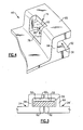
Figure 4 illustrates an example retention feature of a seal channel. -
Figure 5 illustrates an alternate view of the retention feature. -
Figure 6 illustrates a sectional view of the retention feature. -
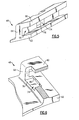
Figure 7 illustrates a perspective view of a tab extending from a feather seal through a slot to retain the feather seal within the seal channel. -
Figure 8 illustrates a sectional view showing an example tab that has been bent. -
Figure 9 illustrates a sectional view of another bent tab. -
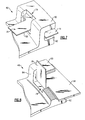
Figure 10 illustrates another embodiment of an example retention feature. -
Figure 11 illustrates an alternate view of the retention feature. -
Figure 12 illustrates a sectional view of the retention feature. -
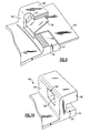
Figure 13 illustrates a sectional view of another bent tab. -
Figure 14 illustrates a sectional view of another bent tab. -
Figure 15 illustrates a sectional view of another bent tab. -
Figure 16 illustrates a sectional view of another bent tab. - The disclosed examples provide a retention feature for use in turbine vanes or other segmented sealed components that limits movement of a feather seal used between the components, such as during assembly of the components.
-
Figure 1 illustrates selected portions of an examplegas turbine engine 10, such as agas turbine engine 10 used for propulsion. In this example, theturbine engine 10 is disposed about anengine centerline 12 and includes afan 14, acompressor section 16, acombustion section 18, and aturbine section 20. Thecombustion section 18 and theturbine section 20 includecorresponding blades 22 andvanes 24. Blade outer air seal segments 26 (shown schematically) are disposed circumferentially about theturbine section 20 to define a hot gas path between an outer structure of thegas turbine engine 10 and theturbine section 20. For example, the segments may form a ring around theengine centerline 12. One non-limiting example of the blade outerair seal segments 26 can be found in United States Patent No.5,639,210 . - As is known, air compressed in the
compressor section 16 is mixed with fuel and burned in thecombustion section 18 to produce hot gases that are expanded in theturbine section 20.Figure 1 is a somewhat schematic presentation for illustrative purposes only and is not a limitation on the disclosed examples. Additionally, there are various types of gas turbine engines, many of which could benefit from the examples disclosed herein, which are not limited to the design shown. -
Figure 2 illustrates an example of one of thevanes 24 from thegas turbine engine 10. For example, a plurality of thevanes 24 are arranged circumferentially about theengine center line 12 in a vane ring assembly. In this example, each of thevanes 24 includes anairfoil section 42 coupled with an inner platform 44 and anouter platform 46. The inner platform 44 is oriented near to theengine center line 12, while theouter platform 46 is oriented away from theengine center line 12. - The inner platform 44 and the
outer platform 46 may be relatively similar with respect to sealing between thevanes 24. For illustrative purposes, theouter platform 46 will be described, although it is to be understood that the disclosed examples may also apply to the inner platform 44. Further, although thevane 24 is the basis of the disclosed examples, the examples are also applicable to theblades 22, the blade outerair seal segments 26, or other segmented sealed components, for example. - In the illustrated example, the
outer platform 46 includes a leadingend 48 and atrailing end 50 that extend betweencircumferential sides circumferential sides seal channel 56. When thevanes 24 are assembled into a vane ring pack, thechannels 56 of onevane 24 are adjacent thechannels 56 of an immediately adjacent vane 24' and form a cavity for receiving afeather seal 58, as illustrated inFigure 3 . - In the illustrated example, each
circumferential side first sidewall 60 and an opposedsecond sidewall 62 that are joined by achannel bottom wall 64 to define theseal channel 56. - Referring also to the portions of the
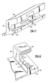
outer platform 46 illustrated inFigures 4-6 , theouter platform 46 includes aretention feature 74 for limiting movement between thefeather seal 58 and theseal channel 56. As discussed above, conventional feather seals may become damaged during assembly into a vane ring assembly. However, theretention feature 74 disclosed herein limits movement of thefeather seal 58 relative to theseal channel 56 during assembly into a vane ring assembly to reduce the opportunity of damaging thefeather seal 58. - As shown, each
circumferential side circumferential sides circumferential sides - In the disclosed example, the
retention feature 74 comprises aslot 76 for receiving a tab 78 (Figure 7 ) that extends generally perpendicularly from amain body 79 of thefeather seal 58. The term "perpendicular" refers to a nominal geometry, such as within a desired tolerance. Theslot 76 and thetab 78 cooperate to limit, and in some examples prevent, circumferential movement of thefeather seal 58 relative to theseal channel 56. The forward and trailing sides of theslot 76 abut the forward and trailing ends of thetab 78 to limit circumferential movement between thefeather seal 58 and theseal channel 56. In some examples, theslot 76 and thetab 78 may also cooperate to limit axial movement of thefeather seal 58, depending on the shape of theslot 76, shape of thetab 78, or the fit between theslot 76 and thetab 78. - The
slot 76 may be any of a variety of different shapes or sizes, depending upon the desired design of thefeather seal 58 or other design considerations. Further, theslot 76 may be formed in the outer platform using a suitable forming method, such as machining, casting, or other known method. In the illustrated example, theslot 76 extends entirely through thechannel bottom wall 64, partially through thechannel sidewall 60 and partially through thechannel sidewall 62. - The
slot 76 includes a recess or step 80 relative to thechannel sidewall 62. Thestep 80 provides the benefit of offsetting the bottom of theslot 76 from thechannel sidewall 62 such that thefeather seal 58 is in a desired seal position that is flush with thechannel sidewall 62. - In one example, the size of the
step 80 is at least as great as the combined ' dimensional variation from the manufacturing of theplatform 46 and theslot 76. For example, casting theplatform 46 may result in a dimensional variation of ± X and machining theslot 76 may result in a dimensional variation of ± Y for aminimum step size 77 of X + Y (Figure 4 ). Designing the size of thestep 80 based on the dimensional variations provides the benefit of assuring that the bottom of theslot 76 is recessed from thechannel sidewall 62 such that the bottom of theslot 76 does not inhibit thefeather seal 58 from sitting flush with thechannel sidewall 62. - Referring to
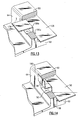
Figures 7 and 8 , thetab 78 of thefeather seal 58 extends through theslot 76 with an adequate amount of clearance such that thetab 78 can be deformed (e.g., bent) to retain thefeather seal 58 in theseal channel 56. Deforming the tab 78 (upwards inFigure 8 ) provides the benefit of locking thefeather seal 58 relative to theseal channel 56 and also preventing axial movement of thefeather seal 58. For example, thetab 78 may be deformed manually and may be deformed to any desired angle. Thus, thefeather seal 58 is thereby secured within theseal channel 56 to reduce the opportunity of damaging thefeather seal 58 during assembly into a vane ring. - Alternatively, as shown in
Figure 9 , thetab 78 is deformed before insertion through theslot 76 such that thetab 78 is non-planar. In this example, thetab 78 is compressed as it is inserted through theslot 76. After the end of thetab 78 clears thechannel sidewall 60, thetab 78 decompresses because of the resilience of the material of thefeather seal 58, such that the end of thetab 78 abuts asurface 81 of thechannel sidewall 60 to retain thefeather seal 58 within theseal channel 56. -
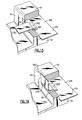
Figures 10 ,11, and 12 illustrate another embodiment retainer feature 74' that includes a slot 76' for retaining thefeather seal 58 in a manner similar to as described above. In this example, the slot 76' extends entirely through thechannel bottom wall 64 and entirely through thechannel sidewall 60, but does not extend at all into thechannel sidewall 62. Thus, in this example, there is a step 80' between thechannel sidewall 62 and the slot 76'. - As shown in
Figure 13 , the slot 76' receives atab 178 of another type offeather seal 158. In this example, thetab 178 includes twocurved sections tab 178 to extend over the step 80' and into the slot 76'. The forward and trailing sides of the slot 76' abut the forward and trailing ends of thetab 178 to limit circumferential movement between thefeather seal 158 and theseal channel 56. Also, the step 80' abuts a portion of atab 178 to limit relative axial movement of thefeather seal 158. - As shown in
Figure 14 , after thetab 178 is received through the slot 76', thetab 178 is deformed such that the end of thetab 178 abuts against acorner 180 between thechannel sidewall 60 and thechannel bottom wall 64 to further limit movement of thefeather seal 58. - Referring to
Figure 15 , anotherembodiment feather seal 258 andtab 278 is shown. In this example, a plane defined by thetab 278 is offset using acurved section 282 from a plane defined by amain body section 279 of thefeather seal 58. Thecurved section 282 allows the tab to extend over the step 80' and into the slot 76'. Similar to thetab 178 of the previous examples, thetab 278 may be deformed upwards as shown inFigure 16 to further limit movement betweenfeather seal 258 and theseal channel 56. - It should be understood that relative positional terms such as "circumferential," "forward," "aft," "upper," "lower," "above," "below," and the like are with reference to the normal operational attitude of the
turbine engine 10 and should not be considered otherwise limiting. - Although a combination of features is shown in the illustrated examples, not all of them need to be combined to realize the benefits of various embodiments of this disclosure. In other words, a system designed according to an embodiment of this disclosure will not necessarily include all of the features shown in any one of the Figures or all of the portions schematically shown in the Figures. Moreover, selected features of one example embodiment may be combined with selected features of other example embodiments.
- The preceding description is exemplary rather than limiting in nature. Variations and modifications to the disclosed examples may become apparent to those skilled in the art that do not necessarily depart from the essence of this disclosure. The scope of legal protection given to this disclosure can only be determined by studying the following claims.
Claims (16)
- A seal component comprising:a body including two circumferential sides (52, 54), a leading end (48), and a trailing end (50), wherein at least one of the circumferential sides includes a first channel sidewall (60), a second channel sidewall (62), and a channel bottom wall (64) that together define a seal channel (56) for receiving a seal (79), and at least one of the first channel sidewall, the second channel sidewall, or the channel bottom wall includes a slot (76) providing a retention feature (74) for limiting movement between the seal and the seal channel.
- The seal component as recited in Claim 1, wherein the slot (76) extends through the channel bottom wall (64).
- The seal component as recited in Claim 2, wherein the slot extends at least partially through the first channel sidewall (60) and the second channel sidewall (62).
- The seal component as recited in Claim 1, 2 or 3, further comprising the seal, wherein the seal includes a corresponding retention feature (78) that cooperates with the retention feature (74) of the seal channel to limit movement between the seal and the seal channel.
- The seal component as recited in Claim 4, wherein the retention feature (74) of the seal channel comprises a slot (76) and the retention feature of the seal comprises a tab (78) that is receivable at least partially within the slot.
- The seal component as recited in Claim 5, wherein the tab (78) is non-planar.
- The seal component as recited in Claim 5, wherein the seal includes a seal body (79) defining a plane and the tab (78) extends from the seal body in a direction that is substantially perpendicular to the plane.
- The seal component as recited in any preceding Claim, wherein the body comprises a platform (46) that is coupled with an airfoil section, and preferably comprises a turbine blade air seal.
- A seal assembly comprising:a first component (24);a second component (24) adjacent the first component, wherein the first component and the second component each include a body (46) having two circumferential sides (52, 54), a leading end (48), and a trailing end (50), wherein one of the circumferential sides of the first component is adjacent one of the circumferential sides of the second component and the circumferential sides each include a seal channel (56), and at least one of the seal channels comprises a first channel sidewall (60), a second channel sidewall (62), and a channel bottom wall (64) that together define the seal channel (56), and at least one of the first channel sidewall, the second channel sidewall, or the channel bottom wall includes a slot (76); anda seal (79) at least partially within the seal channels, the seal including a retention feature (78) that cooperates with the slot to limit movement between the seal and the seal channels.
- The seal assembly as recited in Claim 9, wherein the retention feature comprises a tab (78) that is receivable at least partially within the slot.
- The seal assembly as recited in Claim 10, wherein the tab (78) is non-planar.
- The seal assembly as recited in Claim 9, 10 or 11, wherein the slot extends through the channel bottom wall (64).
- The seal assembly as recited in Claim 9, 10 or 11, wherein the slot extends at least partially through the first channel sidewall and the second channel sidewall.
- A method of assembling a seal and a seal channel of a gas turbine engine component, comprising:providing the seal with a tab and the seal channel with a slot; andinserting the tab at least partially into the slot to limit movement between the seal and the seal channel.
- The method as recited in Claim 14, including deforming the tab after inserting the tab at least partially into the slot.
- The method as recited in Claim 15, including deforming the tab to provide a deformed tab before inserting the tab at least partially into the slot, and compressing the deformed tab to insert the deformed tab through the slot.
Applications Claiming Priority (1)
| Application Number | Priority Date | Filing Date | Title |
|---|---|---|---|
| US11/869,142 US8308428B2 (en) | 2007-10-09 | 2007-10-09 | Seal assembly retention feature and assembly method |
Publications (3)
| Publication Number | Publication Date |
|---|---|
| EP2048328A2 true EP2048328A2 (en) | 2009-04-15 |
| EP2048328A3 EP2048328A3 (en) | 2012-01-18 |
| EP2048328B1 EP2048328B1 (en) | 2019-05-08 |
Family
ID=40303567
Family Applications (1)
| Application Number | Title | Priority Date | Filing Date |
|---|---|---|---|
| EP08252654.2A Not-in-force EP2048328B1 (en) | 2007-10-09 | 2008-08-08 | Seal assembly retention feature |
Country Status (2)
| Country | Link |
|---|---|
| US (2) | US8308428B2 (en) |
| EP (1) | EP2048328B1 (en) |
Cited By (2)
| Publication number | Priority date | Publication date | Assignee | Title |
|---|---|---|---|---|
| EP2841697A4 (en) * | 2012-04-24 | 2016-05-11 | United Technologies Corp | AERODYNAMIC PROFILE WITH ARTICULATED JOINT JOINT ELEMENT |
| US11519286B2 (en) | 2021-02-04 | 2022-12-06 | General Electric Company | Sealing assembly and sealing member therefor with spline seal retention |
Families Citing this family (27)
| Publication number | Priority date | Publication date | Assignee | Title |
|---|---|---|---|---|
| US20090096174A1 (en) * | 2007-02-28 | 2009-04-16 | United Technologies Corporation | Blade outer air seal for a gas turbine engine |
| US20090191050A1 (en) * | 2008-01-24 | 2009-07-30 | Siemens Power Generation, Inc. | Sealing band having bendable tang with anti-rotation in a turbine and associated methods |
| US20110031704A1 (en) * | 2009-05-15 | 2011-02-10 | Lehr Brian C | Segmented Gaskets |
| DE102010021923B4 (en) * | 2010-05-28 | 2013-12-19 | MTU Aero Engines AG | Sealing system for a housing segment of a thermal turbomachine |
| US8820754B2 (en) * | 2010-06-11 | 2014-09-02 | Siemens Energy, Inc. | Turbine blade seal assembly |
| US9403208B2 (en) | 2010-12-30 | 2016-08-02 | United Technologies Corporation | Method and casting core for forming a landing for welding a baffle inserted in an airfoil |
| US8727710B2 (en) | 2011-01-24 | 2014-05-20 | United Technologies Corporation | Mateface cooling feather seal assembly |
| US9016695B2 (en) * | 2011-08-02 | 2015-04-28 | United Technologies Corporation | Gas turbine exhaust nozzle divergent flap seal |
| US10072517B2 (en) | 2013-03-08 | 2018-09-11 | United Technologies Corporation | Gas turbine engine component having variable width feather seal slot |
| US9856737B2 (en) * | 2014-03-27 | 2018-01-02 | United Technologies Corporation | Blades and blade dampers for gas turbine engines |
| US9945256B2 (en) | 2014-06-27 | 2018-04-17 | Rolls-Royce Corporation | Segmented turbine shroud with seals |
| US9938846B2 (en) * | 2014-06-27 | 2018-04-10 | Rolls-Royce North American Technologies Inc. | Turbine shroud with sealed blade track |
| US9677427B2 (en) * | 2014-07-04 | 2017-06-13 | Pratt & Whitney Canada Corp. | Axial retaining ring for turbine vanes |
| US9759079B2 (en) | 2015-05-28 | 2017-09-12 | Rolls-Royce Corporation | Split line flow path seals |
| US9951634B2 (en) * | 2015-06-11 | 2018-04-24 | United Technologies Corporation | Attachment arrangement for turbine engine component |
| US9822658B2 (en) | 2015-11-19 | 2017-11-21 | United Technologies Corporation | Grooved seal arrangement for turbine engine |
| US11225880B1 (en) | 2017-02-22 | 2022-01-18 | Rolls-Royce Corporation | Turbine shroud ring for a gas turbine engine having a tip clearance probe |
| US10941671B2 (en) * | 2017-03-23 | 2021-03-09 | General Electric Company | Gas turbine engine component incorporating a seal slot |
| US10718226B2 (en) | 2017-11-21 | 2020-07-21 | Rolls-Royce Corporation | Ceramic matrix composite component assembly and seal |
| US10907491B2 (en) * | 2017-11-30 | 2021-02-02 | General Electric Company | Sealing system for a rotary machine and method of assembling same |
| US11111802B2 (en) * | 2019-05-01 | 2021-09-07 | Raytheon Technologies Corporation | Seal for a gas turbine engine |
| US11187094B2 (en) * | 2019-08-26 | 2021-11-30 | General Electric Company | Spline for a turbine engine |
| EP3789638A1 (en) * | 2019-09-05 | 2021-03-10 | Siemens Aktiengesellschaft | Seal for combustion apparatus |
| US11187096B2 (en) * | 2019-11-07 | 2021-11-30 | Raytheon Technologies Corporation | Platform seal |
| FR3116860B1 (en) | 2020-11-27 | 2026-01-30 | Safran Aircraft Engines | INSTALLATION AND METHOD FOR ASSEMBLING TURBINE DISTRIBUTORS |
| FR3116746B1 (en) * | 2020-11-27 | 2023-12-22 | Safran Aircraft Engines | AUTOMATED DEVICE FOR INSERTING SEALING PLATES INTO A SECTOR OF A TURBINE DISTRIBUTOR |
| US11536147B2 (en) | 2021-03-30 | 2022-12-27 | Raytheon Technologies Corporation | Vane arc segment with flange and gusset |
Citations (1)
| Publication number | Priority date | Publication date | Assignee | Title |
|---|---|---|---|---|
| US5639210A (en) | 1995-10-23 | 1997-06-17 | United Technologies Corporation | Rotor blade outer tip seal apparatus |
Family Cites Families (30)
| Publication number | Priority date | Publication date | Assignee | Title |
|---|---|---|---|---|
| US2000602A (en) * | 1932-02-02 | 1935-05-07 | Eastman Kodak Co | Process for the fibrous esterification of cellulose |
| US1998791A (en) * | 1934-06-27 | 1935-04-23 | Goodrich Co B F | Sealing strip |
| US3202398A (en) * | 1962-11-05 | 1965-08-24 | James E Webb | Locking device for turbine rotor blades |
| US4549058A (en) | 1983-09-30 | 1985-10-22 | United Technologies Corporation | Feather seal slot for vanes |
| US4557412A (en) | 1983-12-05 | 1985-12-10 | United Technologies Corporation | Intersecting feather seals and construction thereof |
| US4524980A (en) * | 1983-12-05 | 1985-06-25 | United Technologies Corporation | Intersecting feather seals for interlocking gas turbine vanes |
| US4749333A (en) | 1986-05-12 | 1988-06-07 | The United States Of America As Represented By The Secretary Of The Air Force | Vane platform sealing and retention means |
| US4902198A (en) * | 1988-08-31 | 1990-02-20 | Westinghouse Electric Corp. | Apparatus for film cooling of turbine van shrouds |
| US5261790A (en) * | 1992-02-03 | 1993-11-16 | General Electric Company | Retention device for turbine blade damper |
| US5265412A (en) * | 1992-07-28 | 1993-11-30 | General Electric Company | Self-accommodating brush seal for gas turbine combustor |
| US5531457A (en) | 1994-12-07 | 1996-07-02 | Pratt & Whitney Canada, Inc. | Gas turbine engine feather seal arrangement |
| US5738490A (en) * | 1996-05-20 | 1998-04-14 | Pratt & Whitney Canada, Inc. | Gas turbine engine shroud seals |
| GB9611371D0 (en) * | 1996-05-31 | 1996-08-07 | Raychem Sa Nv | Sealed article |
| US5709530A (en) | 1996-09-04 | 1998-01-20 | United Technologies Corporation | Gas turbine vane seal |
| US5868398A (en) | 1997-05-20 | 1999-02-09 | United Technologies Corporation | Gas turbine stator vane seal |
| US5971703A (en) * | 1997-12-05 | 1999-10-26 | Pratt & Whitney Canada Inc. | Seal assembly for a gas turbine engine |
| US6103341A (en) * | 1997-12-08 | 2000-08-15 | L&L Products | Self-sealing partition |
| FR2776012B1 (en) * | 1998-03-12 | 2000-04-07 | Snecma | SEAL OF A CIRCULAR BLADE STAGE |
| EP1371814A1 (en) | 2002-06-11 | 2003-12-17 | ALSTOM (Switzerland) Ltd | Sealing arrangement for a rotor of a turbomachine |
| US6883807B2 (en) * | 2002-09-13 | 2005-04-26 | Seimens Westinghouse Power Corporation | Multidirectional turbine shim seal |
| WO2004074640A1 (en) * | 2003-02-19 | 2004-09-02 | Alstom Technology Ltd | Sealing arrangement, particularly for the blade segments of gas turbines |
| GB2401658B (en) * | 2003-05-16 | 2006-07-26 | Rolls Royce Plc | Sealing arrangement |
| US7217081B2 (en) | 2004-10-15 | 2007-05-15 | Siemens Power Generation, Inc. | Cooling system for a seal for turbine vane shrouds |
| US20060082074A1 (en) | 2004-10-18 | 2006-04-20 | Pratt & Whitney Canada Corp. | Circumferential feather seal |
| JP4822716B2 (en) | 2005-02-07 | 2011-11-24 | 三菱重工業株式会社 | Gas turbine with seal structure |
| US7575415B2 (en) * | 2005-11-10 | 2009-08-18 | General Electric Company | Methods and apparatus for assembling turbine engines |
| US7625174B2 (en) * | 2005-12-16 | 2009-12-01 | General Electric Company | Methods and apparatus for assembling gas turbine engine stator assemblies |
| US20090096174A1 (en) * | 2007-02-28 | 2009-04-16 | United Technologies Corporation | Blade outer air seal for a gas turbine engine |
| FR2915510B1 (en) * | 2007-04-27 | 2009-11-06 | Snecma Sa | SHOCK ABSORBER FOR TURBOMACHINE BLADES |
| US8182208B2 (en) * | 2007-07-10 | 2012-05-22 | United Technologies Corp. | Gas turbine systems involving feather seals |
-
2007
- 2007-10-09 US US11/869,142 patent/US8308428B2/en not_active Expired - Fee Related
-
2008
- 2008-08-08 EP EP08252654.2A patent/EP2048328B1/en not_active Not-in-force
-
2012
- 2012-10-05 US US13/646,281 patent/US8769817B2/en not_active Expired - Fee Related
Patent Citations (1)
| Publication number | Priority date | Publication date | Assignee | Title |
|---|---|---|---|---|
| US5639210A (en) | 1995-10-23 | 1997-06-17 | United Technologies Corporation | Rotor blade outer tip seal apparatus |
Cited By (2)
| Publication number | Priority date | Publication date | Assignee | Title |
|---|---|---|---|---|
| EP2841697A4 (en) * | 2012-04-24 | 2016-05-11 | United Technologies Corp | AERODYNAMIC PROFILE WITH ARTICULATED JOINT JOINT ELEMENT |
| US11519286B2 (en) | 2021-02-04 | 2022-12-06 | General Electric Company | Sealing assembly and sealing member therefor with spline seal retention |
Also Published As
| Publication number | Publication date |
|---|---|
| US20090092485A1 (en) | 2009-04-09 |
| EP2048328A3 (en) | 2012-01-18 |
| US8769817B2 (en) | 2014-07-08 |
| US8308428B2 (en) | 2012-11-13 |
| EP2048328B1 (en) | 2019-05-08 |
| US20130047431A1 (en) | 2013-02-28 |
Similar Documents
| Publication | Publication Date | Title |
|---|---|---|
| EP2048328B1 (en) | Seal assembly retention feature | |
| US8523529B2 (en) | Locking spacer assembly for a circumferential entry airfoil attachment system | |
| US7090466B2 (en) | Methods and apparatus for assembling gas turbine engine rotor assemblies | |
| EP1744013B1 (en) | Method for loading and tangential locking of rotor blades and corresponding rotor blade | |
| US7922444B2 (en) | Chamfer rail pockets for turbine vane shrouds | |
| US7290986B2 (en) | Turbine airfoil with curved squealer tip | |
| EP1944474A2 (en) | Gas turbine shroud seal and corresponding gas turbine engine | |
| US20150064020A1 (en) | Turbine blade or vane with separate endwall | |
| EP2075411A1 (en) | Integrally bladed rotor with slotted outer rim and gas turbine engine comprising such a rotor | |
| US8152454B2 (en) | Stator vane for a gas turbine engine | |
| EP2586993B1 (en) | Feather seal slot | |
| EP2964896B1 (en) | System for preventing leakage in a turbine, corresponding method of preventing air leakage | |
| CN104420891A (en) | Blade of a rotary flow machine with a radial strip seal | |
| EP3315731B1 (en) | Sealing assembly for a gas turbine engine | |
| EP3244015B1 (en) | Stator vane shiplap seal assembly | |
| US10801343B2 (en) | Self retaining face seal design for by-pass stator vanes | |
| EP3090143B1 (en) | Array of components in a gas turbine engine | |
| EP3489464B1 (en) | Seal structure for gas turbine rotor blade | |
| US7399163B2 (en) | Rotor blade for a compressor or a gas turbine | |
| US12372000B2 (en) | Foil, rotor blade, assembly for a turbomachine rotor and rotor | |
| US7458779B2 (en) | Gas turbine or compressor blade | |
| US20180128117A1 (en) | Self-sealing impingement cooling tube for a turbine vane | |
| US11060411B2 (en) | Inner shroud assembly for stator vanes | |
| US10767503B2 (en) | Stator assembly with retention clip for gas turbine engine | |
| EP3059396B1 (en) | Gas turbine engine and turbine configurations |
Legal Events
| Date | Code | Title | Description |
|---|---|---|---|
| PUAI | Public reference made under article 153(3) epc to a published international application that has entered the european phase |
Free format text: ORIGINAL CODE: 0009012 |
|
| AK | Designated contracting states |
Kind code of ref document: A2 Designated state(s): AT BE BG CH CY CZ DE DK EE ES FI FR GB GR HR HU IE IS IT LI LT LU LV MC MT NL NO PL PT RO SE SI SK TR |
|
| AX | Request for extension of the european patent |
Extension state: AL BA MK RS |
|
| PUAL | Search report despatched |
Free format text: ORIGINAL CODE: 0009013 |
|
| AK | Designated contracting states |
Kind code of ref document: A3 Designated state(s): AT BE BG CH CY CZ DE DK EE ES FI FR GB GR HR HU IE IS IT LI LT LU LV MC MT NL NO PL PT RO SE SI SK TR |
|
| AX | Request for extension of the european patent |
Extension state: AL BA MK RS |
|
| RIC1 | Information provided on ipc code assigned before grant |
Ipc: F01D 11/00 20060101AFI20111212BHEP Ipc: F02C 7/28 20060101ALI20111212BHEP Ipc: F01D 9/04 20060101ALI20111212BHEP |
|
| 17P | Request for examination filed |
Effective date: 20120718 |
|
| AKX | Designation fees paid |
Designated state(s): DE GB |
|
| RAP1 | Party data changed (applicant data changed or rights of an application transferred) |
Owner name: UNITED TECHNOLOGIES CORPORATION |
|
| STAA | Information on the status of an ep patent application or granted ep patent |
Free format text: STATUS: EXAMINATION IS IN PROGRESS |
|
| 17Q | First examination report despatched |
Effective date: 20170222 |
|
| GRAP | Despatch of communication of intention to grant a patent |
Free format text: ORIGINAL CODE: EPIDOSNIGR1 |
|
| STAA | Information on the status of an ep patent application or granted ep patent |
Free format text: STATUS: GRANT OF PATENT IS INTENDED |
|
| INTG | Intention to grant announced |
Effective date: 20181119 |
|
| GRAS | Grant fee paid |
Free format text: ORIGINAL CODE: EPIDOSNIGR3 |
|
| GRAA | (expected) grant |
Free format text: ORIGINAL CODE: 0009210 |
|
| STAA | Information on the status of an ep patent application or granted ep patent |
Free format text: STATUS: THE PATENT HAS BEEN GRANTED |
|
| AK | Designated contracting states |
Kind code of ref document: B1 Designated state(s): DE GB |
|
| REG | Reference to a national code |
Ref country code: GB Ref legal event code: FG4D |
|
| REG | Reference to a national code |
Ref country code: DE Ref legal event code: R096 Ref document number: 602008059989 Country of ref document: DE |
|
| PGFP | Annual fee paid to national office [announced via postgrant information from national office to epo] |
Ref country code: DE Payment date: 20190722 Year of fee payment: 12 |
|
| PGFP | Annual fee paid to national office [announced via postgrant information from national office to epo] |
Ref country code: GB Payment date: 20190722 Year of fee payment: 12 |
|
| REG | Reference to a national code |
Ref country code: DE Ref legal event code: R097 Ref document number: 602008059989 Country of ref document: DE |
|
| PLBE | No opposition filed within time limit |
Free format text: ORIGINAL CODE: 0009261 |
|
| STAA | Information on the status of an ep patent application or granted ep patent |
Free format text: STATUS: NO OPPOSITION FILED WITHIN TIME LIMIT |
|
| 26N | No opposition filed |
Effective date: 20200211 |
|
| REG | Reference to a national code |
Ref country code: DE Ref legal event code: R119 Ref document number: 602008059989 Country of ref document: DE |
|
| GBPC | Gb: european patent ceased through non-payment of renewal fee |
Effective date: 20200808 |
|
| PG25 | Lapsed in a contracting state [announced via postgrant information from national office to epo] |
Ref country code: DE Free format text: LAPSE BECAUSE OF NON-PAYMENT OF DUE FEES Effective date: 20210302 |
|
| PG25 | Lapsed in a contracting state [announced via postgrant information from national office to epo] |
Ref country code: GB Free format text: LAPSE BECAUSE OF NON-PAYMENT OF DUE FEES Effective date: 20200808 |