EP2047728B1 - An assembly for mounting electronic components, methods of use and manfacture thereof - Google Patents
An assembly for mounting electronic components, methods of use and manfacture thereof Download PDFInfo
- Publication number
- EP2047728B1 EP2047728B1 EP07813346A EP07813346A EP2047728B1 EP 2047728 B1 EP2047728 B1 EP 2047728B1 EP 07813346 A EP07813346 A EP 07813346A EP 07813346 A EP07813346 A EP 07813346A EP 2047728 B1 EP2047728 B1 EP 2047728B1
- Authority
- EP
- European Patent Office
- Prior art keywords
- retaining element
- diameter
- screw
- assembly
- face plate
- Prior art date
- Legal status (The legal status is an assumption and is not a legal conclusion. Google has not performed a legal analysis and makes no representation as to the accuracy of the status listed.)
- Active
Links
Images




Classifications
-
- H—ELECTRICITY
- H05—ELECTRIC TECHNIQUES NOT OTHERWISE PROVIDED FOR
- H05K—PRINTED CIRCUITS; CASINGS OR CONSTRUCTIONAL DETAILS OF ELECTRIC APPARATUS; MANUFACTURE OF ASSEMBLAGES OF ELECTRICAL COMPONENTS
- H05K7/00—Constructional details common to different types of electric apparatus
- H05K7/14—Mounting supporting structure in casing or on frame or rack
- H05K7/1401—Mounting supporting structure in casing or on frame or rack comprising clamping or extracting means
- H05K7/1402—Mounting supporting structure in casing or on frame or rack comprising clamping or extracting means for securing or extracting printed circuit boards
- H05K7/1407—Mounting supporting structure in casing or on frame or rack comprising clamping or extracting means for securing or extracting printed circuit boards by turn-bolt or screw member
-
- H—ELECTRICITY
- H05—ELECTRIC TECHNIQUES NOT OTHERWISE PROVIDED FOR
- H05K—PRINTED CIRCUITS; CASINGS OR CONSTRUCTIONAL DETAILS OF ELECTRIC APPARATUS; MANUFACTURE OF ASSEMBLAGES OF ELECTRICAL COMPONENTS
- H05K5/00—Casings, cabinets or drawers for electric apparatus
-
- H—ELECTRICITY
- H05—ELECTRIC TECHNIQUES NOT OTHERWISE PROVIDED FOR
- H05K—PRINTED CIRCUITS; CASINGS OR CONSTRUCTIONAL DETAILS OF ELECTRIC APPARATUS; MANUFACTURE OF ASSEMBLAGES OF ELECTRICAL COMPONENTS
- H05K7/00—Constructional details common to different types of electric apparatus
- H05K7/02—Arrangements of circuit components or wiring on supporting structure
- H05K7/12—Resilient or clamping means for holding component to structure
-
- H—ELECTRICITY
- H05—ELECTRIC TECHNIQUES NOT OTHERWISE PROVIDED FOR
- H05K—PRINTED CIRCUITS; CASINGS OR CONSTRUCTIONAL DETAILS OF ELECTRIC APPARATUS; MANUFACTURE OF ASSEMBLAGES OF ELECTRICAL COMPONENTS
- H05K7/00—Constructional details common to different types of electric apparatus
- H05K7/18—Construction of rack or frame
Definitions
- the present invention generally relates to assemblies used for mounting electronic components onto the rack of an electronic device.
- EMI electromagnetic interference
- face plates have been made primarily from metallic plates, and have printed circuit boards (PCBs) mounted onto their interior surface using screws. Face plates also have attachment hardware such as latches and captive screws that are used to mount the faceplate-PCB assembly to a rack.
- the screws generally located at the top and bottom of the assembly, are captive and often have a spring to facilitate assembly and disassembly.
- the captive screws Due to the limitations of the metal face plate manufacturing technology, the captive screws have to be supplied with a standoff to provide an apparatus and method of attachment for the screw-spring assembly to the faceplate. The standoff is press-fit into a hole drilled in the metal faceplate and retained on the faceplate. Examples of face plates with fixing screws are given in US 2004/00 35599 A1 , US 2002/0076264 A1 , US 6,178,092 , US 2002/0096980 .
- an assembly for mounting electronic components comprises a face plate comprising a thermoplastic material.
- the faceplate includes a molded retaining element adapted to secure a captive screw and spring assembly in place.
- the screw and spring assembly is used to mount printed circuit boards onto the face place.
- the retaining element includes at least one or more slots which expand upon insertion of the threaded portion of the screw, and to contract to lock the shank portion of the screw in place when the threaded portion has passed through the hole.
- the retaining element is cylindrical in shape and includes between one and eight slots, preferably four slots.
- the faceplate is preferably fabricated from a thermoplastic material which is either substantially electrically conductive, or is substantially electrically non-conductive with an electrically conductive conformal coating layer.
- the face plate can be advantageously manufactured by injection molding techniques.
- FIGS. 1 to 6 illustrate an assembly for mounting electronic components onto a rack, the captive screws used therein, and the mode of use, according to various embodiments of the present invention.
- an assembly 100 includes a faceplate 110 comprising a thermoplastic material.
- the thermoplastic material is an electrically conductive thermoplastic material.
- the faceplate may comprise a non-conductive thermoplastic that receives a secondary electrically conductive conformal coating.
- Such coatings may be applied using various coating processes including, for example, plating, painting, and thermal spraying among others. While the embodiments described herein have been discussed with respect to certain electrically conductive thermoplastics, those skilled in the art will readily appreciate the application of these embodiments to non-conductive thermoplastics having conductive coatings, and all such embodiments are included within the scope of the invention and captured in the claims.
- FIGS. 1 and 3 illustrate the faceplate 110 comprising retaining elements 120, depicted here as simple holes, that pass through the faceplate 110.
- the retaining elements 120 are generally configured to receive screws, such as, for example, plain screws, captive screws, and tapered screws, among others.
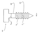
- the screw is a simple captive screw 400 as illustrated in FIG. 4 .
- the screw 400 has screw threads 410 having an inner diameter D SI and an outer diameter D SO , and a shank portion 420 of the screw 400 has a screw shank diameter, D SHANK .
- the captive screw can also include a spring (not shown in drawings) which seats on the screw head, on one end thereof, and which is also adapted to seat in a circular indentation, of diameter D HI , formed in the captive screw retaining element ( FIG. 2 ).
- a spring (not shown in drawings) which seats on the screw head, on one end thereof, and which is also adapted to seat in a circular indentation, of diameter D HI , formed in the captive screw retaining element ( FIG. 2 ).
- the retaining element 120 has a hole of diameter D H which passes through the face plate.
- the hole is sized and configured to interface with the screw thread of the screw, such as, for example, the screw thread 410.
- the retaining element 120 has a circular indentation of diameter D HI (250), which does not pass through the face plate, and an outer periphery (240).
- the retaining element includes one or more slots 230. In the embodiment illustrated by FIG. 2 , the retaining element has four slots 230.
- the retaining element 120 may comprise different numbers of slots, and typically one or more slots. Further, the shape of these slots may vary in certain embodiments. According to certain embodiments, the retaining element 120 comprises one to eight slots, and preferably four slots.
- Each slot 230 may be defined as having an inner periphery 260 (dashed line indicates imaginary boundary), and an outer periphery 240 that borders the periphery of the retaining element 120.
- the outer periphery of the slot 230 may have an outer periphery smaller than the periphery of the retaining element 120.
- the sum of the length of the inner peripheries 260 of the slots 230 is less than 70% of diameter D HI .
- the cumulative inner periphery length of the slots 230 is between about 10% to about 60% of the diameter D HI .
- the hole diameter D H is, in general, larger than the screw shank diameter D SH , but slightly smaller than the outer diameter of the screw D SO to permit engagement of screw thread 410 by the retaining element.
- the diameter D H is between about 50% to about 92% of the outer diameter of the screw thread D SO .
- the diameter D HI is larger than the outer screw thread diameter D SO .
- the diameter D HI is between about 110% to about 200% of the outer diameter of the screw thread D SO .
- the outer diameter of the screw thread D SO is 2.6 millimeters (mm), and the diameter D H is 2 mm.
- the screw 400 in use the screw 400 is tightened into retaining element 120, and the retaining element through hole is configured to bear the load imposed by the screw threads 410. Accordingly, in response, the screw threads 410 and the through hole may undergo some deformation in response to force "C" driving the screw 400 down ( FIG. 5 ). Those skilled in the art will appreciate that the screw threads 410 may also experience some deformation (not shown in the figures). As the screw 400 moves down in the direction of the force, the screw threads 410 emerge out of the hole to present the shank portion to the hole. As the screw shank 420 is exposed to the through hole, the screw 400 it is locked out of movement in the backward direction.
- the material of the faceplate 110 and the retaining element 120 should be strong enough to resist breakage upon insertion of the screw 400 through the retaining element 120.
- the screw threads 410 are fully extended out of the through, and the shank 420 is exposed beyond the last hole thread.
- the screw threads 410 and the hole form a locking configuration preventing the backward movement of the screw 400.
- the slots 230 function to permit expansion of the upper portion of the hole, allowing the threaded portion of the screw to pass through, and contracting after the threaded portion passes through to effectively lock the shank portion of the screw in place.
- the assembly 100 is advantageously a single, molded component, as opposed to a conventional multiple component assembly.
- the present invention further reduces the complexity of manufacture as well as the cost of manufacture, offering substantial cost savings on known applications, such as mounting printed circuit boards (PCB) to a rack in a computer system.
- PCB printed circuit boards
- the method of mounting an electronic component assembly onto the rack comprises providing an assembly, such as the assembly 100, providing a captive screw, such as the captive screw 400, and tightening the screw 400 through the faceplate 110 to the rack, such that the screw threads 410 pass at least partially through the retaining element 120, and the screw shank portion 420 locks, creating a locking configuration with the retaining element 120.
- a method of manufacturing an assembly for mounting electronic components onto a rack includes providing a mold having a cavity in an inverse shape of the assembly 100, especially the faceplate 110 portion, and injecting a thermoplastic material at substantially high pressures such that the thermoplastic material conforms to the shape of the mold cavity after injection at substantially high pressures.
- thermoplastic is a material that is plastic or deformable, melts to a liquid when heated and freezes to a brittle, glassy state when cooled sufficiently.
- Most thermoplastics are high molecular weight polymers whose chains associate through weak van der Waals forces (polyethylene); stronger dipole-dipole interactions and hydrogen bonding (nylon); or even stacking of aromatic rings (polystyrene).
- Thermoplastic polymers differ from thermosetting polymers (Bakelite; vulcanized rubber) as they can, unlike thermosetting polymers, be remelted and remolded.
- Many thermoplastic materials are addition polymers; e.g., vinyl chain-growth polymers such as polyethylene and polypropylene. Further, these thermoplastics may be made conductive using conducting additives, such as, for example, graphite, among others.
- Injection molding is a manufacturing technique for making parts from thermoplastic material in production. Molten plastic is injected at high pressures into a mold, which is the inverse of the product's shape. After a product is designed, molds are made from metal, usually either steel or aluminum, and precision-machined to form the features of the desired part. Injection molding may be used for manufacturing a variety of parts, including small components, and it is the most common method of production due to its ease of use and cost effectiveness. As such, injection molding is a well known technique in the art.
- the main challenge in manufacturing using injection molding is whether the desired part function can be easily implemented using this technique.
- Conventional assemblies such as metal faceplates, and spring loaded standoffs, which are used to mount PCBs onto racks, were typically not injection moldable.
- the present invention advantageously provides for all the features of a standoff in an injection moldable implementation, that is less complex than conventional systems, easy to manufacture, and provides substantial cost savings.
- costs can be reduced by over 15%, accompanied by further reductions in the complexity of manufacture.
- features, such as those described above have been advantageously built into the faceplate 110.
- Such faceplates are advantageously manufactured using injection molding technology that offers the design freedom to include the features described herein.
Landscapes
- Engineering & Computer Science (AREA)
- Microelectronics & Electronic Packaging (AREA)
- Injection Moulding Of Plastics Or The Like (AREA)
- Shielding Devices Or Components To Electric Or Magnetic Fields (AREA)
- Mounting Of Printed Circuit Boards And The Like (AREA)
- Combinations Of Printed Boards (AREA)
Abstract
Description
- The present invention generally relates to assemblies used for mounting electronic components onto the rack of an electronic device.
- In various electronic components, especially in telecommunication equipment, electrically conductive systems are intended to provide shielding against electromagnetic interference (EMI). Face plates are typically used in rack-mounted telecommunication equipment for EMI shielding as described above.
- Conventionally, face plates have been made primarily from metallic plates, and have printed circuit boards (PCBs) mounted onto their interior surface using screws. Face plates also have attachment hardware such as latches and captive screws that are used to mount the faceplate-PCB assembly to a rack. The screws, generally located at the top and bottom of the assembly, are captive and often have a spring to facilitate assembly and disassembly. Due to the limitations of the metal face plate manufacturing technology, the captive screws have to be supplied with a standoff to provide an apparatus and method of attachment for the screw-spring assembly to the faceplate. The standoff is press-fit into a hole drilled in the metal faceplate and retained on the faceplate. Examples of face plates with fixing screws are given in
US 2004/00 35599 A1 ,US 2002/0076264 A1 ,US 6,178,092 ,US 2002/0096980 . - While these conventional technologies work, the complexity of manufacture is generally high. Further, the use of multiple parts required makes it inconvenient and complicated to use for actual mounting. The above inconveniences further increase both the cost of manufacturing as well as the cost of using such assemblies.
- Accordingly, there exists a need for an improved assembly system for mounting a face plate to a rack that overcomes the above mentioned limitations of conventional methods and assemblies.
- According to certain aspects of the invention, an assembly for mounting electronic components comprises a face plate comprising a thermoplastic material. The faceplate includes a molded retaining element adapted to secure a captive screw and spring assembly in place. The screw and spring assembly is used to mount printed circuit boards onto the face place. The retaining element includes at least one or more slots which expand upon insertion of the threaded portion of the screw, and to contract to lock the shank portion of the screw in place when the threaded portion has passed through the hole.
- In other aspects of the invention, the retaining element is cylindrical in shape and includes between one and eight slots, preferably four slots. The faceplate is preferably fabricated from a thermoplastic material which is either substantially electrically conductive, or is substantially electrically non-conductive with an electrically conductive conformal coating layer. The face plate can be advantageously manufactured by injection molding techniques.
- The foregoing and other advantages and features of the invention will become apparent upon reading the following detailed description and upon reference to the drawings in which:
-
FIG. 1 is a perspective view of an assembly according to an aspect of the invention; -
FIG. 2 is a portion of an assembly illustrating a portion of the assembly ofFIG. 1 ; -
FIG. 3 is cross sectional view of the faceplate ofFIG. 2 ; -
FIG. 4 illustrates a screw having a threaded portion and a shank portion; -
FIG. 5 illustrates the partial insertion of a screw into an assembly, according to certain aspects of the present invention; and -
FIG. 6 illustrates a configuration of a screw inserted completely into an assembly, according to various aspects of the present invention. - As used herein, the term "a" refers to "at least one", unless otherwise mentioned.
- The terms "approximately the same" or "approximately equal" refer to nearly the same size with respect to the tolerance for interface, the free relative movement of parts, and the like.
-
FIGS. 1 to 6 illustrate an assembly for mounting electronic components onto a rack, the captive screws used therein, and the mode of use, according to various embodiments of the present invention. - As illustrated in
FIG. 1 , anassembly 100 includes afaceplate 110 comprising a thermoplastic material. In the illustrated embodiments, the thermoplastic material is an electrically conductive thermoplastic material. In other embodiments, the faceplate may comprise a non-conductive thermoplastic that receives a secondary electrically conductive conformal coating. Such coatings may be applied using various coating processes including, for example, plating, painting, and thermal spraying among others. While the embodiments described herein have been discussed with respect to certain electrically conductive thermoplastics, those skilled in the art will readily appreciate the application of these embodiments to non-conductive thermoplastics having conductive coatings, and all such embodiments are included within the scope of the invention and captured in the claims. -
FIGS. 1 and3 illustrate thefaceplate 110 comprisingretaining elements 120, depicted here as simple holes, that pass through thefaceplate 110. Theretaining elements 120 are generally configured to receive screws, such as, for example, plain screws, captive screws, and tapered screws, among others. According to one embodiment of the invention, the screw is a simplecaptive screw 400 as illustrated inFIG. 4 . Thescrew 400 hasscrew threads 410 having an inner diameter DSI and an outer diameter DSO, and ashank portion 420 of thescrew 400 has a screw shank diameter, DSHANK. The captive screw can also include a spring (not shown in drawings) which seats on the screw head, on one end thereof, and which is also adapted to seat in a circular indentation, of diameter DHI, formed in the captive screw retaining element (FIG. 2 ). - As illustrated in
FIG. 2 , theretaining element 120 has a hole of diameter DH which passes through the face plate. The hole is sized and configured to interface with the screw thread of the screw, such as, for example, thescrew thread 410. Further, theretaining element 120 has a circular indentation of diameter DHI (250), which does not pass through the face plate, and an outer periphery (240). The retaining element includes one ormore slots 230. In the embodiment illustrated byFIG. 2 , the retaining element has fourslots 230. Those skilled in the art will appreciate that theretaining element 120 may comprise different numbers of slots, and typically one or more slots. Further, the shape of these slots may vary in certain embodiments. According to certain embodiments, theretaining element 120 comprises one to eight slots, and preferably four slots. - Each
slot 230 may be defined as having an inner periphery 260 (dashed line indicates imaginary boundary), and anouter periphery 240 that borders the periphery of theretaining element 120. In other embodiments, the outer periphery of theslot 230 may have an outer periphery smaller than the periphery of theretaining element 120. According to various embodiments of the invention, the sum of the length of theinner peripheries 260 of theslots 230 is less than 70% of diameter DHI. In the embodiments illustrated in the figures, the cumulative inner periphery length of theslots 230 is between about 10% to about 60% of the diameter DHI. - To accommodate the screw shank portion of the captive screw in a stable configuration, and to retain the screw thread portion in the required position, the hole diameter DH is, in general, larger than the screw shank diameter DSH, but slightly smaller than the outer diameter of the screw DSO to permit engagement of
screw thread 410 by the retaining element. In the illustrated embodiments, the diameter DH is between about 50% to about 92% of the outer diameter of the screw thread DSO. According to various design aspects of the invention, the diameter DHI is larger than the outer screw thread diameter DSO. In the illustrated embodiments, the diameter DHI is between about 110% to about 200% of the outer diameter of the screw thread DSO. Further, in the embodiments illustrated with respect toFIGS. 1 to 6 , the outer diameter of the screw thread DSO is 2.6 millimeters (mm), and the diameter DH is 2 mm. Those skilled in the art will readily be able determine other dimensions based on the particular application using the guidelines disclosed herein with respect to the above embodiments. - As illustrated in
FIGS. 5 and6 , in use thescrew 400 is tightened into retainingelement 120, and the retaining element through hole is configured to bear the load imposed by thescrew threads 410. Accordingly, in response, thescrew threads 410 and the through hole may undergo some deformation in response to force "C" driving thescrew 400 down (FIG. 5 ). Those skilled in the art will appreciate that thescrew threads 410 may also experience some deformation (not shown in the figures). As thescrew 400 moves down in the direction of the force, thescrew threads 410 emerge out of the hole to present the shank portion to the hole. As thescrew shank 420 is exposed to the through hole, thescrew 400 it is locked out of movement in the backward direction. It will be appreciated that the material of thefaceplate 110 and theretaining element 120 should be strong enough to resist breakage upon insertion of thescrew 400 through theretaining element 120. In the embodiment illustrated inFIG. 6 , thescrew threads 410 are fully extended out of the through, and theshank 420 is exposed beyond the last hole thread. Thescrew threads 410 and the hole form a locking configuration preventing the backward movement of thescrew 400. Theslots 230 function to permit expansion of the upper portion of the hole, allowing the threaded portion of the screw to pass through, and contracting after the threaded portion passes through to effectively lock the shank portion of the screw in place. - The
assembly 100 is advantageously a single, molded component, as opposed to a conventional multiple component assembly. The present invention further reduces the complexity of manufacture as well as the cost of manufacture, offering substantial cost savings on known applications, such as mounting printed circuit boards (PCB) to a rack in a computer system. These embodiments and techniques may be applied more advantageously to other applications as well, and all such applications are included within the scope of the claims appended hereto. - Advantageously, these assemblies are simpler to mount onto electronic component racks, such as a rack for mounting PCBs. According to one embodiment of the invention, the method of mounting an electronic component assembly onto the rack (not shown in the figures) comprises providing an assembly, such as the
assembly 100, providing a captive screw, such as thecaptive screw 400, and tightening thescrew 400 through thefaceplate 110 to the rack, such that thescrew threads 410 pass at least partially through the retainingelement 120, and thescrew shank portion 420 locks, creating a locking configuration with the retainingelement 120. - As mentioned above, the present invention provides an assembly that is also easy to manufacture. Accordingly, in one embodiment, a method of manufacturing an assembly for mounting electronic components onto a rack is provided. The method includes providing a mold having a cavity in an inverse shape of the
assembly 100, especially thefaceplate 110 portion, and injecting a thermoplastic material at substantially high pressures such that the thermoplastic material conforms to the shape of the mold cavity after injection at substantially high pressures. - A thermoplastic is a material that is plastic or deformable, melts to a liquid when heated and freezes to a brittle, glassy state when cooled sufficiently. Most thermoplastics are high molecular weight polymers whose chains associate through weak van der Waals forces (polyethylene); stronger dipole-dipole interactions and hydrogen bonding (nylon); or even stacking of aromatic rings (polystyrene). Thermoplastic polymers differ from thermosetting polymers (Bakelite; vulcanized rubber) as they can, unlike thermosetting polymers, be remelted and remolded. Many thermoplastic materials are addition polymers; e.g., vinyl chain-growth polymers such as polyethylene and polypropylene. Further, these thermoplastics may be made conductive using conducting additives, such as, for example, graphite, among others.
- Injection molding is a manufacturing technique for making parts from thermoplastic material in production. Molten plastic is injected at high pressures into a mold, which is the inverse of the product's shape. After a product is designed, molds are made from metal, usually either steel or aluminum, and precision-machined to form the features of the desired part. Injection molding may be used for manufacturing a variety of parts, including small components, and it is the most common method of production due to its ease of use and cost effectiveness. As such, injection molding is a well known technique in the art.
- The main challenge in manufacturing using injection molding is whether the desired part function can be easily implemented using this technique. Conventional assemblies, such as metal faceplates, and spring loaded standoffs, which are used to mount PCBs onto racks, were typically not injection moldable. The present invention advantageously provides for all the features of a standoff in an injection moldable implementation, that is less complex than conventional systems, easy to manufacture, and provides substantial cost savings. On known applications, for example the mounting for a PCB to a typical computer system rack, costs can be reduced by over 15%, accompanied by further reductions in the complexity of manufacture. Those skilled in the art will appreciate that features, such as those described above, have been advantageously built into the
faceplate 110. Such faceplates are advantageously manufactured using injection molding technology that offers the design freedom to include the features described herein. - While the invention may be susceptible to various modifications and alternative forms, specific embodiments have been shown by way of example in the drawings, and have been described in detail herein. However, it should be understood that the invention is not intended to be limited to the particular embodiments disclosed herein. Rather, the invention is intended to cover all modifications, equivalents, and alternatives falling within the scope of the invention as defined by the following appended claims.
Claims (23)
- An assembly for mounting electronic components onto a rack, the assembly comprising:a face plate (110) comprising a thermoplastic material;a captive screw (400) an spring element adapted for insertion in a retaining element (120) molded into the face plate (110), wherein the captive screw (400) as a shank portion (420) and a thread portion (410), the thread portion having an inner diameter DSI and an outer diameter DSO, and the shank portion having a diameter DSHANK, anda retaining element (120) adapted to secure the captive screw (400) in place on the face plate (110), the retaining element (120) having a circular indentation with a diameter DHI extending partially through the retaining element, and a hole within the circular indentation extending through the retaining element (120) with a diameter DH, the retaining element further including at least one slot (230) extending from the outer periphery of hole DH,wherein the retaining element slot (230) enables the retaining element (120) to expand to accommodate the captive screw (400) as the thread portion (410) passes through the hole, and to contract to lock the shank portion (420) of the scree (400) in place when the thread portion (410) of the screw has passed through the hole.
- The assembly of claim 1, wherein diameter DH is about 50% to about 92% of diameter DSO.
- The assembly of claim 1, wherein diameter DHI is between about 110% to about 200% of diameter DSO.
- The assembly of claim 3, wherein diameter DHI is sized to provide a seat for the spring in the captive screw and spring element.
- The assembly of claim 1, wherein the retaining element (120) has a cylindrical shape.
- The assembly of claim 1, wherein the retaining element (120) has from about 1 to about 8 slots.
- The assembly of claim 6, wherein the retaining element (120) has 4 slots.
- The assembly of claim 1, wherein the face plate(110) is manufactured by injection molding.
- The assembly of claim 1, wherein the thermoplastic is substantially electrically conductive.
- The assembly of claim 1, wherein the thermoplastic is substantially electrically non-conductive, and the face plate further comprises an electrically conductive conformal coating layer.
- A method for mounting an electronic component onto a rack without using a standoff, the method comprising:providing an assembly comprisinga face plate (110) comprising a thermoplastic material;a captive screw (400) and spring element adapted for insertion in a retaining element (120) molded into the face plate (110), wherein the captive screw (400) has a shank portion (420) and a thread portion (410), the thread portion having an inner diameter DSI and an outer diameter DSO, and the shank portion having a diameter DSHANK, anda retaining element (120) adapted to secure the captive screw (400) in place on the face plate (110), the retaining element (120) having a circular indentation with a diameter DHI extending partially through the retaining element, and a hole within the circular indentation extending through the retaining element (120) with a diameter DH, the retaining element further including at least one slot (230) extending from the outer periphery of hole DH, andtightening the screw (400) through the face plate (110) to the rack, such that the screw threads pass through the retaining element, and the retaining element (120) locks the screw shank portion in place on the face plate, as slot (230) enables the retraining element to accomodate the captive screw (400) as the thread portion (410) passes through the hole, and to contract to lock the shank portion (420) of the screw in place when the thread portion of the screw has passed through the hole.
- The method of claim 11, wherein diameter DH is about 50% to about 92% of diameter Dso.
- The method of claim 11, wherein diameter DHI is between about 110% to about 200% of diameter DSO.
- The method of claim 13, wherein diameter DHI is sized to provide a seat for the spring in the captive screw and spring element.
- The method of claim 11, wherein the retaining element has a cylindrical shape.
- The method of claim 11, wherein the retaining element has from about 1 to about 8 slots.
- The method of claim 16, wherein the retaining element has 4 slots.
- The method of claim 11, wherein the face plate is manufactured by injection molding.
- The method of claim 11, wherein the thermoplastic is substantially electrically conductive.
- The method of claim 11, wherein the thermoplastic is substantially electrically non-conductive, and the face plate further comprises an electrically conductive conformal coating layer.
- A method of manufacturing an assembly, the method comprising:providing a mold having a cavity in an inverse shape of the assembly, the assembly comprising:a face plate (110) comprising a thermoplastic material;a captive screw (400) and spring element adapted for insertion in a retaining element (120) molded into the face plate, wherein the captive screw has a shank portion (420) and a thread portion (410), the thread portion having an inner diameter DSI and an outer diameter DSO, and the shank portion having a diameter DSHANK, anda retaining element (120) adapted to secure the captive screw (400) in place on the face plate, the retaining element having a circular indentation with a diameter DHI extending partially through the retaining element, and a hole within the circular indentation extending through the retaining element with a diameter DH, the retaining element further including at least one slot (230) extending from the outer periphery of hole DH, the said slot (230) enabling the retaining element (120) to expand to accomodate the captive screw (400) as the thread portion (410) passes through the hole, and to contract to lock the shank portion (420) of the screw (400) in place when the thread portion (410) of the screw has passed through the hole, andinjecting a thermoplastic material into the mold at substantially high pressures such that the thermoplastic material conforms to the shape of the cavity.
- The method of claim 21, wherein the thermoplastic is substantially electrically conductive.
- The method of claim 21, wherein the thermoplastic is substantially electrically non-conductive, and the method further comprises:coating an electrically conductive conformal coating layer over the assembly.
Applications Claiming Priority (2)
| Application Number | Priority Date | Filing Date | Title |
|---|---|---|---|
| US82061906P | 2006-07-28 | 2006-07-28 | |
| PCT/US2007/074329 WO2008014325A2 (en) | 2006-07-28 | 2007-07-25 | An assembly for mounting electronic components, methods of use and manfacture thereof |
Publications (2)
| Publication Number | Publication Date |
|---|---|
| EP2047728A2 EP2047728A2 (en) | 2009-04-15 |
| EP2047728B1 true EP2047728B1 (en) | 2011-09-07 |
Family
ID=38941812
Family Applications (1)
| Application Number | Title | Priority Date | Filing Date |
|---|---|---|---|
| EP07813346A Active EP2047728B1 (en) | 2006-07-28 | 2007-07-25 | An assembly for mounting electronic components, methods of use and manfacture thereof |
Country Status (7)
| Country | Link |
|---|---|
| US (1) | US8439615B2 (en) |
| EP (1) | EP2047728B1 (en) |
| JP (1) | JP4966377B2 (en) |
| KR (1) | KR20090042751A (en) |
| CN (1) | CN101352114B (en) |
| TW (1) | TW200819025A (en) |
| WO (1) | WO2008014325A2 (en) |
Families Citing this family (13)
| Publication number | Priority date | Publication date | Assignee | Title |
|---|---|---|---|---|
| JP2006090343A (en) * | 2004-09-21 | 2006-04-06 | Hitachi Ltd | Bolt support structure of propeller shaft |
| TWM371391U (en) * | 2009-06-04 | 2009-12-21 | Asia Vital Components Co Ltd | Pivot-connection unit and support frame structure thereof |
| US9814190B1 (en) * | 2013-02-01 | 2017-11-14 | Hunter Industries, Inc. | Irrigation controller with robust ground path |
| US9611877B1 (en) * | 2015-01-20 | 2017-04-04 | Gerald E. Attanasio | Honeycomb panel fastener |
| DE102016118630B3 (en) | 2016-09-30 | 2018-02-22 | Fujitsu Limited | computer system |
| CN106782121B (en) * | 2016-12-26 | 2022-12-16 | 深圳市大族元亨光电股份有限公司 | LED display unit screen |
| CN106782120A (en) * | 2016-12-26 | 2017-05-31 | 深圳市大族元亨光电股份有限公司 | LED display modules |
| CN207927103U (en) * | 2018-03-30 | 2018-09-28 | 京东方科技集团股份有限公司 | Connector, display device and vehicle |
| CN110831365A (en) * | 2018-08-10 | 2020-02-21 | 泰连德国有限公司 | Assembly with printed circuit board and method of securing printed circuit board |
| DE102020100438A1 (en) * | 2020-01-10 | 2021-07-15 | Borgwarner Ludwigsburg Gmbh | Automotive component with flange and fastening screw |
| US11121504B2 (en) * | 2020-02-03 | 2021-09-14 | Rockwell Collins, Inc. | Circuit board separation mechanism |
| NL2025247B1 (en) * | 2020-03-31 | 2021-10-22 | Legrand France | A sheet metal part for use in a housing for accommodating devices such as electrical, electronic and optical devices |
| US11985782B2 (en) * | 2022-04-08 | 2024-05-14 | Western Digital Technologies, Inc. | Enclosure fitting for electronic device |
Family Cites Families (29)
| Publication number | Priority date | Publication date | Assignee | Title |
|---|---|---|---|---|
| US1719301A (en) * | 1927-04-21 | 1929-07-02 | Erie Malleable Iron Co | Cover |
| US3018127A (en) * | 1958-10-30 | 1962-01-23 | Westinghouse Electric Corp | Enclosed device with cover-mounting means |
| US4355198A (en) * | 1981-01-19 | 1982-10-19 | Harvey Hubbell Incorporated | Screw retaining and aligning cover plate |
| JPS59158016A (en) * | 1983-02-28 | 1984-09-07 | ティーディーケイ株式会社 | Electromagnetically shielding material |
| US4542372A (en) * | 1983-06-28 | 1985-09-17 | Honeywell Inc. | Data distribution apparatus |
| US4528213A (en) * | 1983-11-22 | 1985-07-09 | Rca Corporation | EMI/RFI Shielding composition |
| JPS6196580U (en) * | 1984-11-28 | 1986-06-21 | ||
| FR2599927A1 (en) * | 1986-06-06 | 1987-12-11 | Alsthom Cgee | Demountable modular front panel for a casing for specialised equipment, especially electronic equipment |
| DE3833032A1 (en) * | 1988-09-29 | 1990-04-05 | Quante Fernmeldetechnik Gmbh | CONNECTING SOCKET FOR TELEPHONE APPARATUS AND / OR TELEPHONE ACCESSORIES |
| EP0579759A1 (en) * | 1991-04-11 | 1994-01-26 | Qube Corporation | Foldable electrical component enclosures |
| US5290132A (en) * | 1993-02-11 | 1994-03-01 | General Motors Corporation | Plastic flash screw clip arrangement |
| US5388940A (en) * | 1993-11-18 | 1995-02-14 | Herren; Harold | Screen rail bolt retainer |
| US5524330A (en) * | 1994-08-17 | 1996-06-11 | 3Com Corporation | Captive screw electronic face plate assembly |
| US6028769A (en) * | 1996-05-20 | 2000-02-22 | Adc Telecommunication, Inc. | Multiple integrated service unit for communication system |
| DE29610693U1 (en) * | 1996-06-18 | 1997-07-17 | Siemens AG, 80333 München | Subrack with insertable assemblies with centerable front panels |
| US5958303A (en) * | 1996-11-07 | 1999-09-28 | Carmel Olefins Ltd | Electrically conductive compositions and methods for producing same |
| US5839868A (en) * | 1997-07-15 | 1998-11-24 | Kloian; Harvey V. | Tearable retainer |
| US20010018979A1 (en) * | 1997-12-10 | 2001-09-06 | Lucent Technologies Inc. | Device and method of forming a unitary electrically shielded panel |
| US5941669A (en) * | 1998-06-18 | 1999-08-24 | Southco, Inc. | Jack-out captivated screw |
| US6281433B1 (en) * | 1999-08-03 | 2001-08-28 | Lucent Technologies Inc. | Faceplate for network switching apparatus |
| US6248262B1 (en) * | 2000-02-03 | 2001-06-19 | General Electric Company | Carbon-reinforced thermoplastic resin composition and articles made from same |
| US20030175091A1 (en) * | 2000-03-10 | 2003-09-18 | Aukzemas Thomas V. | Floating captive screw |
| JP2002181024A (en) * | 2000-12-15 | 2002-06-26 | Nec Corp | Screwing structure |
| US6471310B2 (en) * | 2001-01-22 | 2002-10-29 | Sun Microsystems, Inc. | Circuit board retaining assembly |
| DE10104672B4 (en) * | 2001-02-02 | 2004-04-15 | Kamax-Werke Rudolf Kellermann Gmbh & Co. Kg | Assembly unit consisting of one component and at least one screw |
| TWI309279B (en) * | 2002-12-18 | 2009-05-01 | Southco | Low profile captive screw |
| US6955512B2 (en) * | 2003-07-21 | 2005-10-18 | Hewlett-Packard Development Company, L.P. | Mounting device for securing an electronic device to an equipment rack |
| US6963495B1 (en) * | 2004-06-21 | 2005-11-08 | Computer Network Technology Corporation | EMI shielded chassis for electrical circuitry |
| US6926537B1 (en) * | 2004-06-21 | 2005-08-09 | Amphenol Corporation | Interposer assembly |
-
2007
- 2007-07-25 WO PCT/US2007/074329 patent/WO2008014325A2/en not_active Ceased
- 2007-07-25 JP JP2009521984A patent/JP4966377B2/en not_active Expired - Fee Related
- 2007-07-25 KR KR1020087007537A patent/KR20090042751A/en not_active Withdrawn
- 2007-07-25 EP EP07813346A patent/EP2047728B1/en active Active
- 2007-07-25 CN CN2007800010707A patent/CN101352114B/en not_active Expired - Fee Related
- 2007-07-26 US US11/828,467 patent/US8439615B2/en active Active
- 2007-07-27 TW TW096127554A patent/TW200819025A/en unknown
Also Published As
| Publication number | Publication date |
|---|---|
| KR20090042751A (en) | 2009-04-30 |
| JP2009545176A (en) | 2009-12-17 |
| US20080025813A1 (en) | 2008-01-31 |
| WO2008014325A3 (en) | 2008-04-03 |
| CN101352114B (en) | 2012-04-11 |
| EP2047728A2 (en) | 2009-04-15 |
| WO2008014325A2 (en) | 2008-01-31 |
| US8439615B2 (en) | 2013-05-14 |
| TW200819025A (en) | 2008-04-16 |
| CN101352114A (en) | 2009-01-21 |
| JP4966377B2 (en) | 2012-07-04 |
Similar Documents
| Publication | Publication Date | Title |
|---|---|---|
| US8439615B2 (en) | Assembly for mounting electronic components, methods of use and manufacture thereof | |
| US5452184A (en) | Multi-position PC board fastener with grounding element | |
| US8066461B2 (en) | Threaded fastener | |
| US4502193A (en) | Stand-off fastener | |
| US8434983B2 (en) | Locking assembly | |
| US7083371B2 (en) | Surface mount captive screw ferrule for PCB | |
| US4786225A (en) | Stand-off fastener | |
| US6377445B1 (en) | Motherboard mounting assembly | |
| US4674930A (en) | Stand-off fastener | |
| US20030210532A1 (en) | Movable standoff for mounting a circuit board | |
| US10051758B2 (en) | Chassis with low-cost, tool-less fastening mechanisms for rack mount systems | |
| US6906266B2 (en) | Method and structure for fastening a planar board to a chassis | |
| US20040120126A1 (en) | Circuit board mounting apparatus | |
| US20220194661A1 (en) | Handle having engaging portion | |
| US7085141B2 (en) | Methods and apparatus for holding circuit boards together | |
| KR102069605B1 (en) | Housing with electronic components | |
| US8038451B2 (en) | Multi-board printed circuit assembly having aligned connectors | |
| US20170027070A1 (en) | Housing assembly of a power operated device and method of manufacturing thereof | |
| US6767220B2 (en) | Systems and methods for interconnecting electronic components | |
| US20070064404A1 (en) | Toolless circuit board mount | |
| TW202239290A (en) | Electronic device and fastening structure thereof | |
| CN104144560A (en) | Fixedly installed PCB | |
| US9413105B2 (en) | Carrier for flexible printed circuit | |
| EP4133917B1 (en) | Systems and methods retaining components in an electronic device | |
| JP2007311568A (en) | Printed circuit board with terminal, and its manufacturing method |
Legal Events
| Date | Code | Title | Description |
|---|---|---|---|
| PUAI | Public reference made under article 153(3) epc to a published international application that has entered the european phase |
Free format text: ORIGINAL CODE: 0009012 |
|
| 17P | Request for examination filed |
Effective date: 20080331 |
|
| AK | Designated contracting states |
Kind code of ref document: A2 Designated state(s): AT BE BG CH CY CZ DE DK EE ES FI FR GB GR HU IE IS IT LI LT LU LV MC MT NL PL PT RO SE SI SK TR |
|
| AX | Request for extension of the european patent |
Extension state: AL BA HR MK RS |
|
| RIC1 | Information provided on ipc code assigned before grant |
Ipc: H05K 9/00 20060101AFI20090603BHEP |
|
| DAX | Request for extension of the european patent (deleted) | ||
| RBV | Designated contracting states (corrected) |
Designated state(s): DE FR GB SE |
|
| GRAJ | Information related to disapproval of communication of intention to grant by the applicant or resumption of examination proceedings by the epo deleted |
Free format text: ORIGINAL CODE: EPIDOSDIGR1 |
|
| GRAP | Despatch of communication of intention to grant a patent |
Free format text: ORIGINAL CODE: EPIDOSNIGR1 |
|
| GRAP | Despatch of communication of intention to grant a patent |
Free format text: ORIGINAL CODE: EPIDOSNIGR1 |
|
| RAP1 | Party data changed (applicant data changed or rights of an application transferred) |
Owner name: PARKER-HANNIFIN CORPORATION |
|
| GRAS | Grant fee paid |
Free format text: ORIGINAL CODE: EPIDOSNIGR3 |
|
| GRAA | (expected) grant |
Free format text: ORIGINAL CODE: 0009210 |
|
| REG | Reference to a national code |
Ref country code: GB Ref legal event code: FG4D |
|
| REG | Reference to a national code |
Ref country code: DE Ref legal event code: R096 Ref document number: 602007017047 Country of ref document: DE Effective date: 20111117 |
|
| REG | Reference to a national code |
Ref country code: SE Ref legal event code: TRGR |
|
| PLBE | No opposition filed within time limit |
Free format text: ORIGINAL CODE: 0009261 |
|
| STAA | Information on the status of an ep patent application or granted ep patent |
Free format text: STATUS: NO OPPOSITION FILED WITHIN TIME LIMIT |
|
| 26N | No opposition filed |
Effective date: 20120611 |
|
| REG | Reference to a national code |
Ref country code: DE Ref legal event code: R097 Ref document number: 602007017047 Country of ref document: DE Effective date: 20120611 |
|
| REG | Reference to a national code |
Ref country code: FR Ref legal event code: PLFP Year of fee payment: 9 |
|
| REG | Reference to a national code |
Ref country code: FR Ref legal event code: PLFP Year of fee payment: 10 |
|
| REG | Reference to a national code |
Ref country code: FR Ref legal event code: PLFP Year of fee payment: 11 |
|
| REG | Reference to a national code |
Ref country code: FR Ref legal event code: PLFP Year of fee payment: 12 |
|
| PGFP | Annual fee paid to national office [announced via postgrant information from national office to epo] |
Ref country code: DE Payment date: 20240729 Year of fee payment: 18 |
|
| PGFP | Annual fee paid to national office [announced via postgrant information from national office to epo] |
Ref country code: GB Payment date: 20240729 Year of fee payment: 18 |
|
| PGFP | Annual fee paid to national office [announced via postgrant information from national office to epo] |
Ref country code: FR Payment date: 20240725 Year of fee payment: 18 |
|
| PGFP | Annual fee paid to national office [announced via postgrant information from national office to epo] |
Ref country code: SE Payment date: 20240727 Year of fee payment: 18 |
|
| REG | Reference to a national code |
Ref country code: DE Ref legal event code: R119 Ref document number: 602007017047 Country of ref document: DE |
|
| GBPC | Gb: european patent ceased through non-payment of renewal fee |
Effective date: 20250725 |
|
| PG25 | Lapsed in a contracting state [announced via postgrant information from national office to epo] |
Ref country code: GB Free format text: LAPSE BECAUSE OF NON-PAYMENT OF DUE FEES Effective date: 20250725 |
|
| PG25 | Lapsed in a contracting state [announced via postgrant information from national office to epo] |
Ref country code: DE Free format text: LAPSE BECAUSE OF NON-PAYMENT OF DUE FEES Effective date: 20260203 |
|
| PG25 | Lapsed in a contracting state [announced via postgrant information from national office to epo] |
Ref country code: FR Free format text: LAPSE BECAUSE OF NON-PAYMENT OF DUE FEES Effective date: 20250731 |