EP2046567B1 - Process and apparatus for manufacturing a reinforcing structure for tyres of vehicles - Google Patents
Process and apparatus for manufacturing a reinforcing structure for tyres of vehicles Download PDFInfo
- Publication number
- EP2046567B1 EP2046567B1 EP06795172A EP06795172A EP2046567B1 EP 2046567 B1 EP2046567 B1 EP 2046567B1 EP 06795172 A EP06795172 A EP 06795172A EP 06795172 A EP06795172 A EP 06795172A EP 2046567 B1 EP2046567 B1 EP 2046567B1
- Authority
- EP
- European Patent Office
- Prior art keywords
- strip
- laying
- toroidal support
- presser
- elements
- Prior art date
- Legal status (The legal status is an assumption and is not a legal conclusion. Google has not performed a legal analysis and makes no representation as to the accuracy of the status listed.)
- Active
Links
- 238000004519 manufacturing process Methods 0.000 title claims abstract description 19
- 230000003014 reinforcing effect Effects 0.000 title claims abstract description 18
- 238000000034 method Methods 0.000 title claims description 8
- 239000013536 elastomeric material Substances 0.000 claims abstract description 6
- 230000000712 assembly Effects 0.000 claims description 9
- 238000000429 assembly Methods 0.000 claims description 9
- 230000008878 coupling Effects 0.000 claims description 5
- 238000010168 coupling process Methods 0.000 claims description 5
- 238000005859 coupling reaction Methods 0.000 claims description 5
- 230000000717 retained effect Effects 0.000 claims 1
- 238000005520 cutting process Methods 0.000 description 11
- 238000012937 correction Methods 0.000 description 4
- 239000011324 bead Substances 0.000 description 3
- 230000015572 biosynthetic process Effects 0.000 description 2
- 238000003490 calendering Methods 0.000 description 2
- 150000001875 compounds Chemical class 0.000 description 2
- 239000003431 cross linking reagent Substances 0.000 description 2
- 230000000694 effects Effects 0.000 description 2
- 239000000463 material Substances 0.000 description 2
- 239000002184 metal Substances 0.000 description 2
- 239000004753 textile Substances 0.000 description 2
- 239000000654 additive Substances 0.000 description 1
- 230000002411 adverse Effects 0.000 description 1
- 238000004873 anchoring Methods 0.000 description 1
- 238000005452 bending Methods 0.000 description 1
- 239000011248 coating agent Substances 0.000 description 1
- 238000000576 coating method Methods 0.000 description 1
- 238000010438 heat treatment Methods 0.000 description 1
- 239000004014 plasticizer Substances 0.000 description 1
- 229920000642 polymer Polymers 0.000 description 1
- 238000002360 preparation method Methods 0.000 description 1
- 238000003825 pressing Methods 0.000 description 1
- 239000012763 reinforcing filler Substances 0.000 description 1
- 239000011265 semifinished product Substances 0.000 description 1
- 125000006850 spacer group Chemical group 0.000 description 1
- 238000011144 upstream manufacturing Methods 0.000 description 1
Images


Classifications
-
- B—PERFORMING OPERATIONS; TRANSPORTING
- B29—WORKING OF PLASTICS; WORKING OF SUBSTANCES IN A PLASTIC STATE IN GENERAL
- B29D—PRODUCING PARTICULAR ARTICLES FROM PLASTICS OR FROM SUBSTANCES IN A PLASTIC STATE
- B29D30/00—Producing pneumatic or solid tyres or parts thereof
- B29D30/06—Pneumatic tyres or parts thereof (e.g. produced by casting, moulding, compression moulding, injection moulding, centrifugal casting)
- B29D30/08—Building tyres
- B29D30/10—Building tyres on round cores, i.e. the shape of the core is approximately identical with the shape of the completed tyre
- B29D30/16—Applying the layers; Guiding or stretching the layers during application
- B29D30/165—Applying the layers; Guiding or stretching the layers during application by feeding cut-to-length pieces in a direction parallel to the core axis and placing the pieces side-by-side to form an annular element
-
- B—PERFORMING OPERATIONS; TRANSPORTING
- B29—WORKING OF PLASTICS; WORKING OF SUBSTANCES IN A PLASTIC STATE IN GENERAL
- B29D—PRODUCING PARTICULAR ARTICLES FROM PLASTICS OR FROM SUBSTANCES IN A PLASTIC STATE
- B29D30/00—Producing pneumatic or solid tyres or parts thereof
- B29D30/06—Pneumatic tyres or parts thereof (e.g. produced by casting, moulding, compression moulding, injection moulding, centrifugal casting)
- B29D30/08—Building tyres
- B29D30/10—Building tyres on round cores, i.e. the shape of the core is approximately identical with the shape of the completed tyre
- B29D30/16—Applying the layers; Guiding or stretching the layers during application
- B29D2030/1664—Details, accessories or auxiliary operations not provided for in the other subgroups of B29D30/00
- B29D2030/1685—Details, accessories or auxiliary operations not provided for in the other subgroups of B29D30/00 the layers being applied being already cut to the appropriate length, before the application step
-
- Y—GENERAL TAGGING OF NEW TECHNOLOGICAL DEVELOPMENTS; GENERAL TAGGING OF CROSS-SECTIONAL TECHNOLOGIES SPANNING OVER SEVERAL SECTIONS OF THE IPC; TECHNICAL SUBJECTS COVERED BY FORMER USPC CROSS-REFERENCE ART COLLECTIONS [XRACs] AND DIGESTS
- Y10—TECHNICAL SUBJECTS COVERED BY FORMER USPC
- Y10T—TECHNICAL SUBJECTS COVERED BY FORMER US CLASSIFICATION
- Y10T156/00—Adhesive bonding and miscellaneous chemical manufacture
- Y10T156/12—Surface bonding means and/or assembly means with cutting, punching, piercing, severing or tearing
- Y10T156/13—Severing followed by associating with part from same source
Definitions
- the present invention relates to a process and an apparatus for manufacturing a reinforcing structure for tyres of vehicles through application of strip-like elements in mutual side by side relationship along the circumferential extension of a toroidal support so as to form at least one reinforcing layer having a continuous circumferential extension around a geometric rotation axis.
- Each of said strip-like elements comprises longitudinal reinforcing threadlike elements disposed parallel to each other and at least partly coated with at least one layer of elastomeric material.
- the invention will be depicted with particular reference to manufacture of a belt structure of a tyre. It is however pointed out already now that the apparatus in accordance with the invention can be also used for manufacturing a carcass structure of the tyre or, more generally, any other reinforcing structure comprising cords oriented parallel to each other and according to a predetermined angle relative to an equatorial plane of the tyre itself.
- a tyre for vehicle wheels usually comprises a carcass structure essentially made up of one or more carcass plies of a substantially toroidal shape and having their axially opposite side edges in engagement with respective annular reinforcing structures incorporating circular inserts usually referred to as "bead cores".
- Each annular reinforcing structure is incorporated into a so-called “bead” defined along an inner circumferential edge of the tyre for anchoring of the latter to a corresponding mounting rim.
- a belt structure comprising one or more belt layers in the form of an endless ring and essentially made up of textile or metallic cords suitably oriented with respect to each other and to the cords belonging to the adjacent carcass plies.
- a tread band usually consisting of a strip of elastomeric material of suitable thickness.
- elastomeric material it is intended a compound comprising at least one elastomeric polymer and at least one reinforcing filler.
- this compound further comprises additives such as cross-linking agents and/or plasticizers, for example. Due to the presence of the cross-linking agents, this material can be cross-linked through heating, so as to form the final article of manufacture.
- a pair of sidewalls is applied to the opposite sides of the tyre, each of them coating a side portion of the tyre included between a so-called shoulder region, located close to the corresponding side edge of the tread band, and the corresponding bead.
- the toroidal support When application has been completed, the toroidal support is rotated around its geometric axis according to a predetermined angle, to enable application of a new strip-like segment at a position adjacent to the previously applied one. Sequential repetition of the above described steps causes formation of a belt layer extending along the whole circumferential extension of the toroidal support.
- This lack of contact may cause, in this case too, an insufficient adhesion of the strip-like element, above all at the ends thereof.
- the Applicant has now found that it is possible to ensure a high structural evenness in a reinforcing structure obtained by sequential laying of strip-like elements, by reducing the distance between the element exerting the laying pressure on the strip-like element and the element guiding said strip-like element during this step.
- the Applicant has further found that it is possible to ensure contact between the element exerting the laying pressure on the strip-like element and the toroidal support over the whole width of the strip-like element by dividing this presser element into at least two parts and mounting the two parts of the presser element thus obtained in an independent manner.
- the invention relates to an apparatus for manufacturing a reinforcing structure for tyres of vehicles, according to claim 1.
- the guide element may be advantageously provided to have a C-shaped conformation.
- the guide element should comprise a main body and two prongs defining said cavity together with the main body.
- the prongs are pivotally mounted in an independent manner on the main body, and the guide element comprises spring means acting to keep one end of each of the prongs in contrast relationship with the toroidal support during laying of the strip-like element.
- two second presser elements are provided for each laying assembly and they are mounted in an independent manner.
- the overall width of the second presser rollers is greater than or equal to the width of the strip-like element to be laid down.
- the invention relates to a process for producing tyres according to claim 8.
- an apparatus for manufacturing reinforcing structures for tyres of vehicles in accordance with the present invention has been generally denoted at 1.
- apparatus 1 lends itself to manufacture a belt structure on a toroidal support 3 having an outer surface 3a substantially conforming in shape to the inner configuration of the tyre to be obtained.
- a carcass structure (not shown in the drawings) is applied; said carcass structure can be conveniently formed on the same toroidal support 3 following the description disclosed in anyone of the following patents or patent applications, EP0943421 , EP0928660 , EP98830661.0 , EP98830472.1 , all in the name of the same Applicant.
- the toroidal support 3, not described in detail because it can be manufactured in any convenient manner by a person skilled in the art, can for example consist of a dismountable or collapsible metal drum to facilitate subsequent removal of same from the obtained tyre.
- the belt structure can also be directly manufactured on the carcass structure, suitably stiffened by inflation for example, in this case said carcass structure also performing the function of a toroidal support. It is also to be pointed out that, in case of need, apparatus 1 is adapted to be also used to manufacture the carcass structure itself, or any other reinforcing structure of the tyre.
- Apparatus 1 comprises at least one feeding unit 4 provided to supply strip-like elements 5 of predetermined length, one by one, said strip-like elements being obtained by cutting operations sequentially carried out on at least one continuous ribbon-like element 6 coming from a drawing and/or calendering device, or from a feeding reel not shown in the figures.
- the continuous ribbon-like element 6, and consequently the strip-like elements 5 obtained therefrom, each have a plurality of threadlike elements and/or cords of metallic or textile material, extending parallel to each other along the longitudinal extension of the ribbon-like element and the strip-like element itself, and at least partly coated with a layer of elastomeric material applied through a drawing and/or calendering operation.
- the feeding unit 4 is of known type such as that described in patent application WO01/38077 for example, in the name of the same Applicant, and comprises at least one cutting member 7 designed to cut the continuous ribbon-like element 6 perpendicularly or according to a predetermined inclination relative to the longitudinal extension of same, to obtain the individual strip-like elements 5.
- at least one grip member 8 movable between a first work position at which, as shown in Fig. 3 , it lends itself to engage a final end 6a of the continuous ribbon-like element 6 close to the cutting member 7, and a second work position at which it is spaced apart from the cutting member itself.
- the grip member 8 drives the continuous ribbon-like element 6 so as to stretch it out beyond the cutting member 7 and preferably at a radially approached position relative to the toroidal support 3, over a length corresponding to that of the strip-like element 5 to be obtained following subsequent operation of the cutting member itself.
- Apparatus 1 further comprises at least one laying unit 100 preferably provided with two laying assemblies 9, 9', operating on the continuous ribbon-like element 6 in a region immediately upstream of the cutting member 7.
- the laying assemblies 9, 9' lend themselves to engage each of the strip-like elements 5 sequentially coming out of the feeding unit 4.
- the two laying assemblies 9, 9' operatively cause application of said strip-like elements 5 onto the outer surface 3a of the toroidal support 3, or onto the carcass structure formed thereon, according to a predetermined laying angle relative to a circumferential extension direction of the toroidal support itself.
- the laying angle ⁇ can be easily pre-set either by suitably orienting the laying unit 100 and possibly the feeding unit 4 relative to the toroidal support, or by suitably orienting said toroidal support relative to the laying and feeding units, 100 and 4.
- Each laying assembly 9, 9' comprises at least one presser element 14 movable along the strip-like element 5, in contrast relationship against the outer surface 3a of the toroidal support 3 to cause application of the strip-like element, and at least one guide element 13 to keep the strip-like element 5 centred and guide it during laying.
- the presser element 14 is represented by a rotating roller supported by a supporting arm 28, while the guide element 13 comprises at least one cavity or recess 11 to house said rotating roller 14 at least partly.
- the rotating roller 14 has the task of forcing the strip-like element 5, at the central region thereof, against the toroidal support 3, preventing the strip-like element itself from folding upon itself, by effect of possible angular laying corrections, thus adversely affecting centring with respect to the guide element 13.
- the guide element 13 substantially has a C-shaped conformation.
- the guide element 13 appears to have a main body 2 and two projecting elements such as two prongs 23, adapted to define the housing cavity 11 together with the main body 2.
- the two prongs 23 are pivotally mounted in an independent manner on the main body 2, at 24, and are operationally connected to spring means 26, such as helical springs for example, in turn connected to the main body 2.
- the spring means 26 is connected to one end of prongs 23 and acts so as to maintain the opposite end of same in contrast relationship with the outer surface 3a of the toroidal support 3.
- the inner distance between the prongs 23, i.e. the width of cavity 11, must be greater than the width of the strip-like element to be laid down so as to maintain the strip-like element 5 internally centred to guide it during laying on the outer surface 3a of the toroidal support 3.
- the inner distance between the prongs 23 is greater than the width of the rotating presser roller 14.
- the guide element 13 further has a curvilinear counter-surface 34 on which the strip-like element 5 slides in a position of contrast with the presser roller 14 and a metal flap 35 supporting and retaining the ends of the strip-like element 5 at the final laying instants.
- the guide element 13 is supported by an arm 33 movable along a guide structure upon the action of transverse-movement devices, of the worm screw type for example, not shown as they can be made in any manner convenient for a person skilled in the art.
- two second presser elements 10 are provided for each laying assembly 9, 9'.
- the second presser elements 10 are embodied by rotating rollers.
- the overall width of the two second presser rollers 10 must be greater than the width of the strip-like element 5 so that during laying, pressure can be exerted on the end tips of the strip-like elements possibly deformed by effect of an angular laying correction, if any.
- the second presser rollers 10 are mounted in a mutually independent manner to ensure that the same will stay in contrast relationship against the outer surface of the toroidal support 3 for the whole laying trajectory, above all at the shoulders of the toroidal support 3.
- each second presser roller 10 is rotatably supported by a support lever 12 pivotally mounted in an independent manner on a supporting element 28 adapted to bear the first presser element 13 too, by means of a bracket 27.
- each supporting arm 28 has two projecting elements 29 of a substantially L-shaped conformation and adapted to carry the rotation centre on which the support levers 12 are pivotally mounted.
- the supporting arms 28 can rotate relative to an end thereof.
- the supporting arms 28 can angularly rotate about a longitudinal extension axis X-X' passing through an end thereof.
- Angular rotation of arms 28 causes rotation of the respective presser elements 14, 10 between a rest position at which, as shown in Fig. 3 , they are moved apart from a longitudinal movement trajectory imposed to the continuous ribbon-like element 6 by the grip member 8, and a work position at which, as shown in Fig. 4 , they are disposed on said movement trajectory and act in coupling relationship with the guide elements 13 and the continuous ribbon-like element interposed therebetween.
- the presser element 14 is housed within cavity 11 at least partly.
- the guide element is provided with two spacers 37 adapted to come into engagement with the supporting arms 28.
- radial-movement devices designed to cause translation of each laying assembly 9, 9', once coupling between rollers 14, 10 and guide element 13 has occurred, radially close to or away from the outer surface 3a of the toroidal support 3.
- transverse-movement devices not shown too as they can be made in any convenient manner, and which operate on arms 28 or arms 33 for example, to cause translation of each laying assembly 9, 9', once the above mentioned coupling has occurred, between a first operating condition at which, as shown in Fig. 5 , they are disposed close to each other and a second operating condition at which, as shown in Fig. 6 , they are spaced apart from an equatorial plane of the toroidal support 3.
- the grip member 8 is brought to the first work position to engage the final end 6a of the continuous ribbon-like element 6 close to the cutting member 7 ( Fig. 3 ).
- the grip member 8 reaches the second work position, angular rotation of the supporting arms 28 is caused, so as to bring the presser elements 14, 10 in engagement relationship with the continuous ribbon-like element 6 driven by the grip member itself, and with the respective guide elements 13 under it.
- the presser elements 14, 10 are brought into coupling relationship with the respective guide elements 13.
- the cutting member 7 is actuated for carrying out cutting of the strip-like element 5.
- the guide elements co-operate with the first presser rollers 14 to retain the strip-like element 5, transversely stretched out in a substantially centred position relative to the equatorial plane of the toroidal support 3.
- simultaneous translation of the first 14 and second 10 presser rollers is determined along the strip-like segment 5, away from the equatorial plane, so as to determine application of the strip-like element 5 onto the toroidal support 3, over the whole length thereof, by a pressing action progressively extending towards the opposite ends of the strip-like element itself, starting from the central portion of the latter.
- an angular rotation of the toroidal support 3 is caused around its geometric axis X-X according to a predetermined angular pitch, to prepare it for application of a new strip-like element 5.
- Sequential repetition of the above described operations causes formation of belt 2 made up of at least one layer having a continuous circumferential extension around the geometric rotation axis X-X and formed of a plurality of strip-like elements 5 distributed in side by side relationship along the circumferential extension of the toroidal support 3.
Abstract
Description
- The present invention relates to a process and an apparatus for manufacturing a reinforcing structure for tyres of vehicles through application of strip-like elements in mutual side by side relationship along the circumferential extension of a toroidal support so as to form at least one reinforcing layer having a continuous circumferential extension around a geometric rotation axis.
- Each of said strip-like elements comprises longitudinal reinforcing threadlike elements disposed parallel to each other and at least partly coated with at least one layer of elastomeric material.
- In the present specification, the invention will be depicted with particular reference to manufacture of a belt structure of a tyre. It is however pointed out already now that the apparatus in accordance with the invention can be also used for manufacturing a carcass structure of the tyre or, more generally, any other reinforcing structure comprising cords oriented parallel to each other and according to a predetermined angle relative to an equatorial plane of the tyre itself.
- A tyre for vehicle wheels usually comprises a carcass structure essentially made up of one or more carcass plies of a substantially toroidal shape and having their axially opposite side edges in engagement with respective annular reinforcing structures incorporating circular inserts usually referred to as "bead cores". Each annular reinforcing structure is incorporated into a so-called "bead" defined along an inner circumferential edge of the tyre for anchoring of the latter to a corresponding mounting rim.
- Applied to the carcass structure, at a radially external position, is a belt structure comprising one or more belt layers in the form of an endless ring and essentially made up of textile or metallic cords suitably oriented with respect to each other and to the cords belonging to the adjacent carcass plies.
- Also applied to the belt structure, at a radially external position, is a tread band usually consisting of a strip of elastomeric material of suitable thickness. It is to be pointed out that, to the aims of the present description, by the term "elastomeric material" it is intended a compound comprising at least one elastomeric polymer and at least one reinforcing filler. Preferably, this compound further comprises additives such as cross-linking agents and/or plasticizers, for example. Due to the presence of the cross-linking agents, this material can be cross-linked through heating, so as to form the final article of manufacture.
- A pair of sidewalls is applied to the opposite sides of the tyre, each of them coating a side portion of the tyre included between a so-called shoulder region, located close to the corresponding side edge of the tread band, and the corresponding bead.
- Recently, particular attention has been paid to the possibility of finding production methods enabling manufacture of intermediate semi-finished products to be eliminated or at least reduced, in the field of tyre building. For instance, in the European Patent Application
EP0928680 in the name of the same Applicant, it is described a method of manufacturing tyres in which the carcass ply or plies, as well as each of the belt layers, are obtained by laying a plurality of strip-like elements one after the other in circumferential side by side relationship, on a toroidal support conforming in shape to the inner conformation of the tyre to be obtained. - In document
US6355126 it is described a method and an apparatus for manufacturing a belt layer through laying of strip-like elements cut from a continuous ribbon-like element. Each strip-like element, once cut from the continuous ribbon-like element, is picked up by grip members of the magnetic type or provided with suction cups, controlled by one ore more robotized arms. The grip members retain the strip-like element at the opposite ends of same, and possibly at a central portion thereof, and are moved upon command of the robotized arms to cause application of the strip-like element itself onto the outer surface of a toroidal support, according to a predetermined angle relative to the circumferential extension of said support. When application has been completed, the toroidal support is rotated around its geometric axis according to a predetermined angle, to enable application of a new strip-like segment at a position adjacent to the previously applied one. Sequential repetition of the above described steps causes formation of a belt layer extending along the whole circumferential extension of the toroidal support. - In document
WO01/38077 - The Applicant has however perceived that laying of strip-like elements carried out following the teachings of the known art could determine unevenness in the reinforcing structure.
- In particular, the Applicant has noticed that in the laying apparatus according to application
WO01/38077 - The Applicant has further noticed that in laying apparatus for strip-like elements of the known art it is not possible to maintain a contact between the element exerting a laying pressure and the supporting drum, over the whole width of the presser element along all the laying outline, above all with high-camber outlines of the toroidal support, such as the toroidal supports used for motorcycle tyres for example.
- This lack of contact may cause, in this case too, an insufficient adhesion of the strip-like element, above all at the ends thereof.
- The Applicant has now found that it is possible to ensure a high structural evenness in a reinforcing structure obtained by sequential laying of strip-like elements, by reducing the distance between the element exerting the laying pressure on the strip-like element and the element guiding said strip-like element during this step.
- The Applicant has further found that it is possible to ensure contact between the element exerting the laying pressure on the strip-like element and the toroidal support over the whole width of the strip-like element by dividing this presser element into at least two parts and mounting the two parts of the presser element thus obtained in an independent manner.
- In a first aspect, the invention relates to an apparatus for manufacturing a reinforcing structure for tyres of vehicles, according to claim 1.
- In case of need, the guide element may be advantageously provided to have a C-shaped conformation.
- It is also preferably provided that the guide element should comprise a main body and two prongs defining said cavity together with the main body.
- In another preferred aspect of the present invention, the prongs are pivotally mounted in an independent manner on the main body, and the guide element comprises spring means acting to keep one end of each of the prongs in contrast relationship with the toroidal support during laying of the strip-like element.
- Preferably, two second presser elements are provided for each laying assembly and they are mounted in an independent manner.
- According to a preferred embodiment, the overall width of the second presser rollers is greater than or equal to the width of the strip-like element to be laid down.
- In a further aspect, the invention relates to a process for producing tyres according to
claim 8. - Further features and advantages of the present invention will become more apparent from the detailed description of a preferred but not exclusive embodiment of an apparatus for manufacturing a reinforcing structure for tyres of vehicles according to the present invention. This description will be set out hereinafter with reference to the accompanying drawings, given by way of non-limiting example, in which:
-
Fig. 1 diagrammatically shows an apparatus according to the invention in an operating step during which a strip-like element is about to be laid onto a toroidal support; -
Fig. 2 is a diagrammatic exploded view of a laying assembly according to the present invention; -
Fig. 3 diagrammatically shows the apparatus seen inFig. 1 , in which one end of a continuous ribbon-like element is about to be grasped by a grip element; -
Fig. 4 shows a step subsequent toFig. 3 , in which the ribbon-like element has been stretched out next to the toroidal support and engaged by the laying unit; -
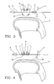
Fig. 5 shows a step subsequent toFig. 4 , in which the strip-like element is about to be applied, at a central portion thereof, onto the toroidal support; and -
Fig. 6 shows a final step for application of the strip-like element. - With reference to the drawings, an apparatus for manufacturing reinforcing structures for tyres of vehicles in accordance with the present invention has been generally denoted at 1.
- In the embodiment described, apparatus 1 lends itself to manufacture a belt structure on a
toroidal support 3 having anouter surface 3a substantially conforming in shape to the inner configuration of the tyre to be obtained. - Preferably, before carrying out manufacture of the belt structure, a carcass structure (not shown in the drawings) is applied; said carcass structure can be conveniently formed on the same
toroidal support 3 following the description disclosed in anyone of the following patents or patent applications,EP0943421 ,EP0928660 ,EP98830661.0 EP98830472.1 toroidal support 3, not described in detail because it can be manufactured in any convenient manner by a person skilled in the art, can for example consist of a dismountable or collapsible metal drum to facilitate subsequent removal of same from the obtained tyre. However, the belt structure can also be directly manufactured on the carcass structure, suitably stiffened by inflation for example, in this case said carcass structure also performing the function of a toroidal support. It is also to be pointed out that, in case of need, apparatus 1 is adapted to be also used to manufacture the carcass structure itself, or any other reinforcing structure of the tyre. - Apparatus 1 comprises at least one feeding unit 4 provided to supply strip-
like elements 5 of predetermined length, one by one, said strip-like elements being obtained by cutting operations sequentially carried out on at least one continuous ribbon-like element 6 coming from a drawing and/or calendering device, or from a feeding reel not shown in the figures. The continuous ribbon-like element 6, and consequently the strip-like elements 5 obtained therefrom, each have a plurality of threadlike elements and/or cords of metallic or textile material, extending parallel to each other along the longitudinal extension of the ribbon-like element and the strip-like element itself, and at least partly coated with a layer of elastomeric material applied through a drawing and/or calendering operation. - The feeding unit 4 is of known type such as that described in patent application
WO01/38077 cutting member 7 designed to cut the continuous ribbon-like element 6 perpendicularly or according to a predetermined inclination relative to the longitudinal extension of same, to obtain the individual strip-like elements 5. Combined with thecutting member 7 is at least onegrip member 8 movable between a first work position at which, as shown inFig. 3 , it lends itself to engage a final end 6a of the continuous ribbon-like element 6 close to thecutting member 7, and a second work position at which it is spaced apart from the cutting member itself. As shown inFig. 4 , following translation from the first to the second work positions, thegrip member 8 drives the continuous ribbon-like element 6 so as to stretch it out beyond thecutting member 7 and preferably at a radially approached position relative to thetoroidal support 3, over a length corresponding to that of the strip-like element 5 to be obtained following subsequent operation of the cutting member itself. - Apparatus 1 further comprises at least one
laying unit 100 preferably provided with twolaying assemblies 9, 9', operating on the continuous ribbon-like element 6 in a region immediately upstream of thecutting member 7. - The
laying assemblies 9, 9' lend themselves to engage each of the strip-like elements 5 sequentially coming out of the feeding unit 4. The two layingassemblies 9, 9' operatively cause application of said strip-like elements 5 onto theouter surface 3a of thetoroidal support 3, or onto the carcass structure formed thereon, according to a predetermined laying angle relative to a circumferential extension direction of the toroidal support itself. - The laying angle α can be easily pre-set either by suitably orienting the
laying unit 100 and possibly the feeding unit 4 relative to the toroidal support, or by suitably orienting said toroidal support relative to the laying and feeding units, 100 and 4. - Each
laying assembly 9, 9' comprises at least onepresser element 14 movable along the strip-like element 5, in contrast relationship against theouter surface 3a of thetoroidal support 3 to cause application of the strip-like element, and at least oneguide element 13 to keep the strip-like element 5 centred and guide it during laying. - The
presser element 14 is represented by a rotating roller supported by a supportingarm 28, while theguide element 13 comprises at least one cavity or recess 11 to house said rotatingroller 14 at least partly. The rotatingroller 14 has the task of forcing the strip-like element 5, at the central region thereof, against thetoroidal support 3, preventing the strip-like element itself from folding upon itself, by effect of possible angular laying corrections, thus adversely affecting centring with respect to theguide element 13. According to an advantageous aspect of the present invention, theguide element 13 substantially has a C-shaped conformation. In more detail, still according to a preferred embodiment, theguide element 13 appears to have a main body 2 and two projecting elements such as twoprongs 23, adapted to define thehousing cavity 11 together with the main body 2. - As shown in
Fig. 1 , the twoprongs 23 are pivotally mounted in an independent manner on the main body 2, at 24, and are operationally connected tospring means 26, such as helical springs for example, in turn connected to the main body 2. - The spring means 26 is connected to one end of
prongs 23 and acts so as to maintain the opposite end of same in contrast relationship with theouter surface 3a of thetoroidal support 3. - The inner distance between the
prongs 23, i.e. the width ofcavity 11, must be greater than the width of the strip-like element to be laid down so as to maintain the strip-like element 5 internally centred to guide it during laying on theouter surface 3a of thetoroidal support 3. - Preferably, the inner distance between the
prongs 23 is greater than the width of therotating presser roller 14. - The
guide element 13 further has a curvilinear counter-surface 34 on which the strip-like element 5 slides in a position of contrast with thepresser roller 14 and ametal flap 35 supporting and retaining the ends of the strip-like element 5 at the final laying instants. According to a preferred embodiment shown in the figures, theguide element 13 is supported by anarm 33 movable along a guide structure upon the action of transverse-movement devices, of the worm screw type for example, not shown as they can be made in any manner convenient for a person skilled in the art. - To lay the strip-
like element 5 onto theouter surface 3a of thetoroidal support 3 over the whole width thereof, use of at least onesecond presser element 10 of suitable width is provided for each layingassembly 9, 9', said second presser element being disposed downstream of thefirst presser element 14. - In detail, in the preferred embodiment shown in the figures, two
second presser elements 10 are provided for each layingassembly 9, 9'. In a preferred aspect, thesecond presser elements 10 are embodied by rotating rollers. The overall width of the twosecond presser rollers 10 must be greater than the width of the strip-like element 5 so that during laying, pressure can be exerted on the end tips of the strip-like elements possibly deformed by effect of an angular laying correction, if any. According to an advantageous aspect of the present invention, thesecond presser rollers 10 are mounted in a mutually independent manner to ensure that the same will stay in contrast relationship against the outer surface of thetoroidal support 3 for the whole laying trajectory, above all at the shoulders of thetoroidal support 3. - To this aim, each
second presser roller 10 is rotatably supported by asupport lever 12 pivotally mounted in an independent manner on a supportingelement 28 adapted to bear thefirst presser element 13 too, by means of abracket 27. - Also provided is the presence of further spring means such as
helical springs 39 disposed between said support levers 12 and the supportingarms 28 to keep eachroller 10 in contrast relationship, in an independent manner, against theouter surface 3a of thetoroidal support 3. - In detail, each supporting
arm 28 has two projectingelements 29 of a substantially L-shaped conformation and adapted to carry the rotation centre on which the support levers 12 are pivotally mounted. - It is further to be noticed that the supporting
arms 28 can rotate relative to an end thereof. In fact, to promote translation of thegrip member 8 between the first and second operating positions in the absence of mechanical interferences and to facilitate engagement between the strip-like element 5 coming out of the feeding device 4 and each layingassembly 9, 9', the supportingarms 28 can angularly rotate about a longitudinal extension axis X-X' passing through an end thereof. - Angular rotation of
arms 28 causes rotation of therespective presser elements Fig. 3 , they are moved apart from a longitudinal movement trajectory imposed to the continuous ribbon-like element 6 by thegrip member 8, and a work position at which, as shown inFig. 4 , they are disposed on said movement trajectory and act in coupling relationship with theguide elements 13 and the continuous ribbon-like element interposed therebetween. In detail, at the end of the rotation of the supportingarms 28 thepresser element 14 is housed withincavity 11 at least partly. To establish the correct position of thepresser element 13 withincavity 11, the guide element is provided with twospacers 37 adapted to come into engagement with the supportingarms 28. - Also associated with the laying
unit 10, are radial-movement devices designed to cause translation of each layingassembly 9, 9', once coupling betweenrollers guide element 13 has occurred, radially close to or away from theouter surface 3a of thetoroidal support 3. - These radial-movement devices are not shown or described in detail because they can be made in any manner convenient for a person skilled in the art.
- Also provided are transverse-movement devices, not shown too as they can be made in any convenient manner, and which operate on
arms 28 orarms 33 for example, to cause translation of each layingassembly 9, 9', once the above mentioned coupling has occurred, between a first operating condition at which, as shown inFig. 5 , they are disposed close to each other and a second operating condition at which, as shown inFig. 6 , they are spaced apart from an equatorial plane of thetoroidal support 3. - Preparation and laying of each strip-
like element 5 using the apparatus according to the present invention substantially takes place following the teachings of Patent ApplicationWO01/38077 - Starting from the condition shown in
Fig. 3 , thegrip member 8 is brought to the first work position to engage the final end 6a of the continuous ribbon-like element 6 close to the cutting member 7 (Fig. 3 ). When thegrip member 8 reaches the second work position, angular rotation of the supportingarms 28 is caused, so as to bring thepresser elements respective guide elements 13 under it. In other words, thepresser elements respective guide elements 13. - Then operation of the cutting
member 7 is actuated for carrying out cutting of the strip-like element 5. Under this circumstance, the guide elements co-operate with thefirst presser rollers 14 to retain the strip-like element 5, transversely stretched out in a substantially centred position relative to the equatorial plane of thetoroidal support 3. - Also determined is translation of the
laying assemblies 9, 9' towards thetoroidal support 3 so that the strip-like element 5 is radially moved close to thetoroidal support 3, brought into contact with and pressed, at its central portion, against theouter surface 3a, in the vicinity of the equatorial plane of the toroidal support itself. By mutual moving apart of thelaying assemblies 9, 9', simultaneous translation of the first 14 and second 10 presser rollers is determined along the strip-like segment 5, away from the equatorial plane, so as to determine application of the strip-like element 5 onto thetoroidal support 3, over the whole length thereof, by a pressing action progressively extending towards the opposite ends of the strip-like element itself, starting from the central portion of the latter. - Subsequently, an angular rotation of the
toroidal support 3 is caused around its geometric axis X-X according to a predetermined angular pitch, to prepare it for application of a new strip-like element 5. Sequential repetition of the above described operations causes formation of belt 2 made up of at least one layer having a continuous circumferential extension around the geometric rotation axis X-X and formed of a plurality of strip-like elements 5 distributed in side by side relationship along the circumferential extension of thetoroidal support 3. - It is further to be pointed out that, based on the teachings of Patent Application
WO01/38077 like element 5 and avoiding problems connected with surface bending of thetoroidal support 3, a relative angular rotation is carried out during application of each strip-like element 5, between the strip-like element itself and thetoroidal support 3, around a correction axis that is substantially radial to the geometric rotation axis of the toroidal support.
Claims (9)
- An apparatus for manufacturing a reinforcing structure for tyres of vehicles, comprising:- a feeding unit (4) to supply strip-like elements (5), each comprising threadlike elements disposed parallel to each other and at least partly coated with at least one layer of elastomeric material;- a laying unit (100) comprising at least one laying assembly (9, 9') to apply each of said strip-like elements (5) onto a toroidal support (3), according to a predetermined laying angle (α) relative to a circumferential extension direction of the toroidal support itself;- said laying assembly (9, 9') comprising at least one presser element (14), movable in contrast relationship against the outer surface (3a) of the toroidal support (3) and at least one guide element (13) to guide said strip-like element (5) during laying of same, wherein said guide element (13) comprises at least one cavity (11) in which said presser element (14) is at least partly housed during laying of said strip-like element (5);characterized in that each laying assembly (9, 9') further comprises at least one second presser element (10) disposed downstream of said first presser element (14) to lay said strip-like element (5) on the outer surface (3a) of said toroidal support (3) over the whole width thereof.
- An apparatus as claimed in claim 1, wherein said guide element (13) has a C-shaped conformation.
- An apparatus as claimed in claim 1, wherein said guide element (13) comprises a main body (2) and two prongs (23) defining said cavity (11) together with said main body (2).
- An apparatus as claimed in claim 3, wherein said prongs (23) are pivotally mounted in an independent manner on said main body (2), and wherein said guide element (13) comprises spring means (7) acting to keep one end of each of said prongs (3) in contrast relationship with the toroidal support, during laying of the strip-like element (5).
- An apparatus as claimed in claim 1, wherein said at least one second presser element (10) consists of two presser elements for each laying assembly (9, 9') and they are mounted in an independent manner.
- An apparatus as claimed in claim 5, wherein the overall width of the second presser rollers (10) is greater than or equal to the width of the strip-like element (5) to be laid down.
- An apparatus as claimed in claim 1 or 5, wherein second spring means (39) is provided to keep said second presser element (10) in contrast relationship against the outer surface (3a) of the toroidal support (3) during laying of said strip-like element (5).
- A process for producing tyres on a toroidal support, which tyres comprise a reinforcing structure made up of at least one layer having a continuous circumferential extension around the geometric rotation axis X-X of a toroidal support (3) and formed of a plurality of strip-like elements (5) distributed in mutual side by side relationship along the circumferential extension of said toroidal support (3) comprising an outer surface (3a),
the process comprising the following steps:a) bringing two first presser elements (14) in coupling relationship with two respective guide elements (13) to form two laying assemblies (9, 9') so as to retain a strip-like element (5);b) translating the laying assemblies (9, 9') towards the toroidal support (3) so that the strip-like element (5) is radially moved close to the toroidal support (3) until it comes into contact with the outer surface (3a) of said toroidal support (3) enabling it to be pressed at its central portion close to the equatorial plane of said toroidal support (3);c) moving said laying assemblies (9, 9') away from each other, to simultaneously translate said first presser elements (14) along the strip-like element (5), away from the equatorial plane, to cause application of the strip-like element (5) in such a manner that the strip-like element is retained and guided by said laying assemblies substantially along all its longitudinal extension;d) angularly rotating said toroidal support (3) around a geometric axis X-X thereof according to a predetermined angular pitch, to make it ready for application of a new strip-like element (5);e) sequentially repeating steps a) to d) to obtain the reinforcing structure;characterized in that in step a) at least two second presser elements (10) are brought into engagement with said strip-like element (5), each of them being disposed downstream of one said first presser element (14) to lay said strip-like element (5) on the outer surface (3a) of said toroidal support (3) over the whole width thereof. - A process as claimed in claim 8, wherein during step a) each first presser element (14) is at least partly housed in a cavity (11) formed in the respective guide element (13).
Applications Claiming Priority (1)
| Application Number | Priority Date | Filing Date | Title |
|---|---|---|---|
| PCT/IB2006/002070 WO2008015486A1 (en) | 2006-07-28 | 2006-07-28 | Process and apparatus for manufacturing a reinforcing structure for tyres of vehicles |
Publications (2)
| Publication Number | Publication Date |
|---|---|
| EP2046567A1 EP2046567A1 (en) | 2009-04-15 |
| EP2046567B1 true EP2046567B1 (en) | 2010-11-03 |
Family
ID=37871886
Family Applications (1)
| Application Number | Title | Priority Date | Filing Date |
|---|---|---|---|
| EP06795172A Active EP2046567B1 (en) | 2006-07-28 | 2006-07-28 | Process and apparatus for manufacturing a reinforcing structure for tyres of vehicles |
Country Status (6)
| Country | Link |
|---|---|
| US (1) | US8342220B2 (en) |
| EP (1) | EP2046567B1 (en) |
| CN (1) | CN101511572B (en) |
| AT (1) | ATE486712T1 (en) |
| DE (1) | DE602006018079D1 (en) |
| WO (1) | WO2008015486A1 (en) |
Families Citing this family (4)
| Publication number | Priority date | Publication date | Assignee | Title |
|---|---|---|---|---|
| BRPI0722003B1 (en) * | 2007-09-10 | 2018-03-20 | Pirelli Tyre S.P.A. | PROCESS TO PRODUCE TIRES ON A TOROID SUPPORT, AND APPARATUS TO MANUFACTURE A VEHICLE TIRE REINFORCEMENT STRUCTURE |
| WO2009068939A1 (en) * | 2007-11-30 | 2009-06-04 | Pirelli Tyre S.P.A. | Process and apparatus for manufacturing tyres for vehicle wheels |
| BR112012008016B1 (en) * | 2009-10-13 | 2019-12-03 | Pirelli | process and apparatus for constructing vehicle wheel tires |
| IT1403131B1 (en) | 2010-12-14 | 2013-10-04 | Pirelli | PROCESS AND EQUIPMENT TO CARRY OUT A REINFORCEMENT STRUCTURE OF A TIRE FOR VEHICLE WHEELS. |
Family Cites Families (20)
| Publication number | Priority date | Publication date | Assignee | Title |
|---|---|---|---|---|
| US3321105A (en) * | 1964-02-04 | 1967-05-23 | Flinchbaugh Products Inc | Label dispenser |
| US3990933A (en) * | 1974-01-09 | 1976-11-09 | Minnesota Mining And Manufacturing Company | Tape applying device |
| JPH05124131A (en) * | 1991-10-30 | 1993-05-21 | Bridgestone Corp | Winder for beltlike member |
| JPH07164559A (en) * | 1993-12-13 | 1995-06-27 | Toyo Tire & Rubber Co Ltd | Molder for cap ply of automobile tire |
| US5979531A (en) * | 1997-10-01 | 1999-11-09 | Mcdonnell Douglas Corporation | Bi-directional fiber placement head |
| WO1999017920A1 (en) | 1997-10-03 | 1999-04-15 | Bridgestone Corporation | Method and apparatus for forming tire reinforcing layer |
| EP0943421B1 (en) | 1997-11-28 | 2003-05-28 | Pirelli Pneumatici Societa' Per Azioni | A method for making tyres for vehicle wheels |
| ES2195109T3 (en) | 1997-12-30 | 2003-12-01 | Pirelli | PROCEDURE FOR THE MANUFACTURE OF TIRES FOR VEHICLE WHEELS. |
| US6026883A (en) * | 1998-04-30 | 2000-02-22 | Alliant Techsystems, Inc. | Self-contained apparatus for fiber element placement |
| US6457504B1 (en) | 1998-07-31 | 2002-10-01 | Pirelli Pneumatici S.P.A. | Carcass structure for vehicle tires |
| US6763868B1 (en) | 1998-07-31 | 2004-07-20 | Pirelli Pneumatici S.P.A. | Tire for a two-wheeled vehicle and carcass structure for the tire |
| US6941992B2 (en) | 1998-10-30 | 2005-09-13 | Pirelli Pneumatici S.P.A. | Tire for a vehicle wheel and method of manufacturing the tire |
| JP4943615B2 (en) * | 1999-11-26 | 2012-05-30 | ピレリ・タイヤ・ソチエタ・ペル・アツィオーニ | Method and apparatus for manufacturing a reinforcing structure for automotive tires |
| FR2815287A1 (en) * | 2000-10-18 | 2002-04-19 | Sedepro | MANUFACTURE OF A STRIP BY EXTRUSION OF A TUBE THEN FLATTENING THE TUBE |
| ES2286252T3 (en) * | 2001-01-12 | 2007-12-01 | Bridgestone Corporation | METHOD OF MANUFACTURE OF A STRUCTURAL ELEMENT OF A COVER, AND APPLIANCE FOR THE SAME. |
| JP4787430B2 (en) | 2001-07-23 | 2011-10-05 | 株式会社ブリヂストン | Method for forming cord reinforcing layer for tire |
| EP1448401A1 (en) * | 2001-11-27 | 2004-08-25 | PIRELLI PNEUMATICI S.p.A. | Method for forming a belt structure for tyres of vehicle wheels and radial tyre including such belt |
| DE60312986T2 (en) | 2002-06-03 | 2007-12-13 | Société de Technologie Michelin | DEVICE FOR PRODUCING A REINFORCEMENT STRUCTURE FOR A TIRE WITH A THREADED TURNING MECHANISM |
| US20060096711A1 (en) | 2002-07-25 | 2006-05-11 | Nobuyuki Suda | Tire component affixing device |
| US7462252B2 (en) * | 2004-06-22 | 2008-12-09 | Illininois Tool Works Inc. | Label applicator with single air cylinder actuator and spring-loaded hinged pad |
-
2006
- 2006-07-28 US US12/309,683 patent/US8342220B2/en active Active
- 2006-07-28 CN CN2006800558647A patent/CN101511572B/en active Active
- 2006-07-28 AT AT06795172T patent/ATE486712T1/en not_active IP Right Cessation
- 2006-07-28 EP EP06795172A patent/EP2046567B1/en active Active
- 2006-07-28 WO PCT/IB2006/002070 patent/WO2008015486A1/en active Application Filing
- 2006-07-28 DE DE602006018079T patent/DE602006018079D1/en active Active
Also Published As
| Publication number | Publication date |
|---|---|
| CN101511572A (en) | 2009-08-19 |
| CN101511572B (en) | 2012-07-25 |
| ATE486712T1 (en) | 2010-11-15 |
| US8342220B2 (en) | 2013-01-01 |
| WO2008015486A1 (en) | 2008-02-07 |
| EP2046567A1 (en) | 2009-04-15 |
| DE602006018079D1 (en) | 2010-12-16 |
| US20090236029A1 (en) | 2009-09-24 |
Similar Documents
| Publication | Publication Date | Title |
|---|---|---|
| EP2200814B1 (en) | Process and apparatus for manufacturing a reinforcing structure for tyres of vehicles | |
| EP1147007B1 (en) | Method and apparatus for manufacturing a reinforcing structure for tyres of vehicles | |
| US10899095B2 (en) | Process and apparatus for building tyres for vehicle wheels | |
| KR101369386B1 (en) | Process and Apparatus for Manufacturing Tyres for Vehicle Wheels | |
| JP5265251B2 (en) | Cord cutting device | |
| EP2032350A1 (en) | Process and apparatus for manufacturing a pneumatic tyre | |
| US20100200151A1 (en) | Process and apparatus for building pneumatic tyres | |
| US9254618B2 (en) | Method for manufacturing a tyre and apparatus for laying a reinforcing element on a forming support | |
| EP2046567B1 (en) | Process and apparatus for manufacturing a reinforcing structure for tyres of vehicles | |
| US9314982B2 (en) | Process and apparatus for manufacturing a reinforcing structure for tyres of vehicles | |
| EP2200815B1 (en) | Process for manufacturing a reinforcing structure for vehicle tyres | |
| US20120241065A1 (en) | Process for building tyres for vehicle wheels and tyre for vehicle wheels | |
| JP5215047B2 (en) | Single line ply manufacturing method | |
| EP3487693B1 (en) | Method and apparatus for building tyres for vehicle wheels | |
| EP2021167A1 (en) | Process and apparatus for manufacturing a pneumatic tyre |
Legal Events
| Date | Code | Title | Description |
|---|---|---|---|
| PUAI | Public reference made under article 153(3) epc to a published international application that has entered the european phase |
Free format text: ORIGINAL CODE: 0009012 |
|
| 17P | Request for examination filed |
Effective date: 20090121 |
|
| AK | Designated contracting states |
Kind code of ref document: A1 Designated state(s): AT BE BG CH CY CZ DE DK EE ES FI FR GB GR HU IE IS IT LI LT LU LV MC NL PL PT RO SE SI SK TR |
|
| AX | Request for extension of the european patent |
Extension state: AL BA HR MK RS |
|
| 17Q | First examination report despatched |
Effective date: 20090806 |
|
| GRAP | Despatch of communication of intention to grant a patent |
Free format text: ORIGINAL CODE: EPIDOSNIGR1 |
|
| DAX | Request for extension of the european patent (deleted) | ||
| GRAS | Grant fee paid |
Free format text: ORIGINAL CODE: EPIDOSNIGR3 |
|
| GRAA | (expected) grant |
Free format text: ORIGINAL CODE: 0009210 |
|
| AK | Designated contracting states |
Kind code of ref document: B1 Designated state(s): AT BE BG CH CY CZ DE DK EE ES FI FR GB GR HU IE IS IT LI LT LU LV MC NL PL PT RO SE SI SK TR |
|
| REG | Reference to a national code |
Ref country code: GB Ref legal event code: FG4D |
|
| REG | Reference to a national code |
Ref country code: CH Ref legal event code: EP |
|
| REG | Reference to a national code |
Ref country code: IE Ref legal event code: FG4D |
|
| REF | Corresponds to: |
Ref document number: 602006018079 Country of ref document: DE Date of ref document: 20101216 Kind code of ref document: P |
|
| REG | Reference to a national code |
Ref country code: RO Ref legal event code: EPE |
|
| REG | Reference to a national code |
Ref country code: NL Ref legal event code: VDEP Effective date: 20101103 |
|
| LTIE | Lt: invalidation of european patent or patent extension |
Effective date: 20101103 |
|
| PG25 | Lapsed in a contracting state [announced via postgrant information from national office to epo] |
Ref country code: LT Free format text: LAPSE BECAUSE OF FAILURE TO SUBMIT A TRANSLATION OF THE DESCRIPTION OR TO PAY THE FEE WITHIN THE PRESCRIBED TIME-LIMIT Effective date: 20101103 |
|
| PG25 | Lapsed in a contracting state [announced via postgrant information from national office to epo] |
Ref country code: FI Free format text: LAPSE BECAUSE OF FAILURE TO SUBMIT A TRANSLATION OF THE DESCRIPTION OR TO PAY THE FEE WITHIN THE PRESCRIBED TIME-LIMIT Effective date: 20101103 Ref country code: SE Free format text: LAPSE BECAUSE OF FAILURE TO SUBMIT A TRANSLATION OF THE DESCRIPTION OR TO PAY THE FEE WITHIN THE PRESCRIBED TIME-LIMIT Effective date: 20101103 Ref country code: NL Free format text: LAPSE BECAUSE OF FAILURE TO SUBMIT A TRANSLATION OF THE DESCRIPTION OR TO PAY THE FEE WITHIN THE PRESCRIBED TIME-LIMIT Effective date: 20101103 Ref country code: LV Free format text: LAPSE BECAUSE OF FAILURE TO SUBMIT A TRANSLATION OF THE DESCRIPTION OR TO PAY THE FEE WITHIN THE PRESCRIBED TIME-LIMIT Effective date: 20101103 Ref country code: PT Free format text: LAPSE BECAUSE OF FAILURE TO SUBMIT A TRANSLATION OF THE DESCRIPTION OR TO PAY THE FEE WITHIN THE PRESCRIBED TIME-LIMIT Effective date: 20110303 Ref country code: BG Free format text: LAPSE BECAUSE OF FAILURE TO SUBMIT A TRANSLATION OF THE DESCRIPTION OR TO PAY THE FEE WITHIN THE PRESCRIBED TIME-LIMIT Effective date: 20110203 Ref country code: IS Free format text: LAPSE BECAUSE OF FAILURE TO SUBMIT A TRANSLATION OF THE DESCRIPTION OR TO PAY THE FEE WITHIN THE PRESCRIBED TIME-LIMIT Effective date: 20110303 Ref country code: AT Free format text: LAPSE BECAUSE OF FAILURE TO SUBMIT A TRANSLATION OF THE DESCRIPTION OR TO PAY THE FEE WITHIN THE PRESCRIBED TIME-LIMIT Effective date: 20101103 Ref country code: SI Free format text: LAPSE BECAUSE OF FAILURE TO SUBMIT A TRANSLATION OF THE DESCRIPTION OR TO PAY THE FEE WITHIN THE PRESCRIBED TIME-LIMIT Effective date: 20101103 |
|
| PG25 | Lapsed in a contracting state [announced via postgrant information from national office to epo] |
Ref country code: GR Free format text: LAPSE BECAUSE OF FAILURE TO SUBMIT A TRANSLATION OF THE DESCRIPTION OR TO PAY THE FEE WITHIN THE PRESCRIBED TIME-LIMIT Effective date: 20110204 |
|
| PG25 | Lapsed in a contracting state [announced via postgrant information from national office to epo] |
Ref country code: EE Free format text: LAPSE BECAUSE OF FAILURE TO SUBMIT A TRANSLATION OF THE DESCRIPTION OR TO PAY THE FEE WITHIN THE PRESCRIBED TIME-LIMIT Effective date: 20101103 Ref country code: ES Free format text: LAPSE BECAUSE OF FAILURE TO SUBMIT A TRANSLATION OF THE DESCRIPTION OR TO PAY THE FEE WITHIN THE PRESCRIBED TIME-LIMIT Effective date: 20110214 Ref country code: CZ Free format text: LAPSE BECAUSE OF FAILURE TO SUBMIT A TRANSLATION OF THE DESCRIPTION OR TO PAY THE FEE WITHIN THE PRESCRIBED TIME-LIMIT Effective date: 20101103 Ref country code: BE Free format text: LAPSE BECAUSE OF FAILURE TO SUBMIT A TRANSLATION OF THE DESCRIPTION OR TO PAY THE FEE WITHIN THE PRESCRIBED TIME-LIMIT Effective date: 20101103 |
|
| PG25 | Lapsed in a contracting state [announced via postgrant information from national office to epo] |
Ref country code: SK Free format text: LAPSE BECAUSE OF FAILURE TO SUBMIT A TRANSLATION OF THE DESCRIPTION OR TO PAY THE FEE WITHIN THE PRESCRIBED TIME-LIMIT Effective date: 20101103 Ref country code: PL Free format text: LAPSE BECAUSE OF FAILURE TO SUBMIT A TRANSLATION OF THE DESCRIPTION OR TO PAY THE FEE WITHIN THE PRESCRIBED TIME-LIMIT Effective date: 20101103 Ref country code: DK Free format text: LAPSE BECAUSE OF FAILURE TO SUBMIT A TRANSLATION OF THE DESCRIPTION OR TO PAY THE FEE WITHIN THE PRESCRIBED TIME-LIMIT Effective date: 20101103 |
|
| PLBE | No opposition filed within time limit |
Free format text: ORIGINAL CODE: 0009261 |
|
| STAA | Information on the status of an ep patent application or granted ep patent |
Free format text: STATUS: NO OPPOSITION FILED WITHIN TIME LIMIT |
|
| 26N | No opposition filed |
Effective date: 20110804 |
|
| REG | Reference to a national code |
Ref country code: DE Ref legal event code: R097 Ref document number: 602006018079 Country of ref document: DE Effective date: 20110804 |
|
| PG25 | Lapsed in a contracting state [announced via postgrant information from national office to epo] |
Ref country code: MC Free format text: LAPSE BECAUSE OF NON-PAYMENT OF DUE FEES Effective date: 20110731 |
|
| REG | Reference to a national code |
Ref country code: CH Ref legal event code: PL |
|
| REG | Reference to a national code |
Ref country code: IE Ref legal event code: MM4A |
|
| PG25 | Lapsed in a contracting state [announced via postgrant information from national office to epo] |
Ref country code: CH Free format text: LAPSE BECAUSE OF NON-PAYMENT OF DUE FEES Effective date: 20110731 Ref country code: LI Free format text: LAPSE BECAUSE OF NON-PAYMENT OF DUE FEES Effective date: 20110731 |
|
| PG25 | Lapsed in a contracting state [announced via postgrant information from national office to epo] |
Ref country code: IE Free format text: LAPSE BECAUSE OF NON-PAYMENT OF DUE FEES Effective date: 20110728 |
|
| PG25 | Lapsed in a contracting state [announced via postgrant information from national office to epo] |
Ref country code: CY Free format text: LAPSE BECAUSE OF EXPIRATION OF PROTECTION Effective date: 20101103 Ref country code: LU Free format text: LAPSE BECAUSE OF NON-PAYMENT OF DUE FEES Effective date: 20110728 |
|
| PG25 | Lapsed in a contracting state [announced via postgrant information from national office to epo] |
Ref country code: TR Free format text: LAPSE BECAUSE OF FAILURE TO SUBMIT A TRANSLATION OF THE DESCRIPTION OR TO PAY THE FEE WITHIN THE PRESCRIBED TIME-LIMIT Effective date: 20101103 |
|
| PG25 | Lapsed in a contracting state [announced via postgrant information from national office to epo] |
Ref country code: HU Free format text: LAPSE BECAUSE OF FAILURE TO SUBMIT A TRANSLATION OF THE DESCRIPTION OR TO PAY THE FEE WITHIN THE PRESCRIBED TIME-LIMIT Effective date: 20101103 |
|
| REG | Reference to a national code |
Ref country code: FR Ref legal event code: PLFP Year of fee payment: 11 |
|
| REG | Reference to a national code |
Ref country code: FR Ref legal event code: PLFP Year of fee payment: 12 |
|
| REG | Reference to a national code |
Ref country code: FR Ref legal event code: PLFP Year of fee payment: 13 |
|
| PGFP | Annual fee paid to national office [announced via postgrant information from national office to epo] |
Ref country code: RO Payment date: 20230707 Year of fee payment: 18 Ref country code: IT Payment date: 20230720 Year of fee payment: 18 Ref country code: GB Payment date: 20230727 Year of fee payment: 18 |
|
| PGFP | Annual fee paid to national office [announced via postgrant information from national office to epo] |
Ref country code: FR Payment date: 20230725 Year of fee payment: 18 Ref country code: DE Payment date: 20230727 Year of fee payment: 18 |