EP2045943A1 - Mimo demodulator and method - Google Patents
Mimo demodulator and method Download PDFInfo
- Publication number
- EP2045943A1 EP2045943A1 EP06781379A EP06781379A EP2045943A1 EP 2045943 A1 EP2045943 A1 EP 2045943A1 EP 06781379 A EP06781379 A EP 06781379A EP 06781379 A EP06781379 A EP 06781379A EP 2045943 A1 EP2045943 A1 EP 2045943A1
- Authority
- EP
- European Patent Office
- Prior art keywords
- channel
- data
- channel estimate
- mimo
- transmitting antennas
- Prior art date
- Legal status (The legal status is an assumption and is not a legal conclusion. Google has not performed a legal analysis and makes no representation as to the accuracy of the status listed.)
- Granted
Links
Images



Classifications
-
- H—ELECTRICITY
- H04—ELECTRIC COMMUNICATION TECHNIQUE
- H04L—TRANSMISSION OF DIGITAL INFORMATION, e.g. TELEGRAPHIC COMMUNICATION
- H04L25/00—Baseband systems
- H04L25/02—Details ; arrangements for supplying electrical power along data transmission lines
- H04L25/0202—Channel estimation
- H04L25/0204—Channel estimation of multiple channels
-
- H—ELECTRICITY
- H04—ELECTRIC COMMUNICATION TECHNIQUE
- H04L—TRANSMISSION OF DIGITAL INFORMATION, e.g. TELEGRAPHIC COMMUNICATION
- H04L25/00—Baseband systems
- H04L25/02—Details ; arrangements for supplying electrical power along data transmission lines
- H04L25/0202—Channel estimation
- H04L25/0224—Channel estimation using sounding signals
Definitions
- the present invention relates to an MIMO demodulator and MIMO demodulation method for performing channel demultiplexing of received data in an MIMO (Multi Input Multi Output) system in which different data streams are transmitted from a plurality of transmitting antennas using the same bandwidth and the transmitted data streams are received by a plurality of antennas.
- MIMO Multi Input Multi Output
- the data rate (i.e., the throughput) can be increased in proportion to the number of transmitting antennas within the given bandwidth.
- S-PARC Selective Per-Antenna Rate Control
- SINR Signal-to-Interference and Noise power Ratio
- the channel estimates are periodically calculated from the received data and used for the computation for channel demultiplexing. For example, as described in JP 2001-522166A , if the calculated channel estimates are linearly interpolated to reduce the range of received data to which the same channel estimate is applied, it is possible to quickly cope with fast fading, but this requires a large amount of computing resources.
- an MIMO (Multi Input Multi Output) demodulator for performing channel demultiplexing of data transmitted from a plurality of transmitting antennas and received by a plurality of receiving antennas, comprising: a channel estimator calculating a channel estimate based on the received data; a channel estimate adjusting circuit changing, for the channel estimate calculated by the channel estimator, a range of data to which the same channel estimate is to be applied, based on the number of transmitting antennas used for transmitting the data; and an MIMO demultiplexer performing MIMO demultiplexing on the received data by using the channel estimate whose applicable data range has been adjusted by the channel estimate adjusting circuit.
- the channel estimate adjusting circuit reduces the range of data to which the same channel estimate is to be applied.
- the range of data to which the same channel estimate is to be applied is reduced by quickly responding to the change in the propagation environment. Then, by making effective use of the computing resources rendered idle when the propagation environment deteriorates, it is possible to accurately cope with fast fading.
- the following description is given by taking as an example a case where transmissions from three antennas are stopped in a system that transmits signals from four antennas and receives the signals by four antennas, but generally, the following description is applicable to a case where a transmission or transmissions from selected antenna or antennas are stopped in a system that transmits signals from a plurality of antennas and receives the signals by a plurality of antennas.
- FIG. 1 shows one example of an MIMO system to which the present invention is applied.
- a transmitter 10 transmits different channel-coded data streams from four transmitting antennas 12 using the same frequency band.
- Figure 2 shows one example of the frame format of the data transmitted from the transmitter 10 to the receiver 16.
- One frame consists of a data channel (CH) 20 and a pilot CH 22 preceding it.
- the pilot signals comprising mutually orthogonal codes (known patterns) from the respective transmitting antennas are received in multiplexed form by the respective receiving antennas; therefore, by taking correlation with each known pattern for each received signal, the complex number indicating the amplitude and phase of the pilot signal from each transmitting antenna is determined and, by dividing it by a predetermined value, the channel estimate h ij is calculated.
- an average value ⁇ 0(n) taken between the channel estimate h(n) determined for the pilot CH in the n-th frame and the channel estimate h(n+1) determined for the pilot CH in the (n+1)th frame is used as the channel estimate ⁇ (n) that is used for channel demultiplexing of the data CH in the n-th frame (n).
- computing resources are made available for each frame so that the computation for the channel demultiplexing using the channel estimates ⁇ 0(n) completes within one frame period.
- the period of the data CH 20 is divided into four sections, and the computation is performed using four different channel estimates ⁇ 0(n), ⁇ 1(n), ⁇ 2(n), and ⁇ 3(n) calculated for the respective sections by linear interpolation from h(n) and h(n+1).
- the data of N symbol intervals within one frame is divided into four parts, and the four different channel estimates are sequentially applied to the respective data of N/4 symbol intervals.
- Figure 5 shows one configuration example of the receiver 16 that implements the above process.
- a channel estimator 32 calculates the channel estimate ⁇ 0(n) from the amplitude and phase of the pilot signal contained in the received data in the pilot CH from among the data received by a receiving section 30, and a linear interpolator 34 calculates the channel estimates ⁇ 0(n), ⁇ 1(n), ⁇ 2(n), and ⁇ 3(n) by linear interpolation.
- a channel estimate selector 36 selects the channel estimates ⁇ 0(n), ⁇ 1(n), ⁇ 2(n), and ⁇ 3(n) obtained by linear interpolation from adjacent channel estimates when the number of transmitting antennas is reduced to one, or otherwise selects the channel estimate ⁇ 0(n) obtained by taking an average between the adjacent channel estimates, and supplies the selected channel estimates to an MIMO demultiplexer 38.
- the MIMO demultiplexer 38 uses the channel estimates selected by the channel estimate selector 36, the MIMO demultiplexer 38 performs the channel demultiplexing by applying a demultiplexing algorithm, such as an MMSE (Minimum Mean Square Error) algorithm or an MLD (Maximum Likelihood Detection) algorithm, to the received data in the data CH period.
- MMSE Minimum Mean Square Error
- MLD Maximum Likelihood Detection
- the number of transmitting antennas that is used by the channel estimate selector 36 use may be made of the number of transmitting antennas that is transmitted from the transmitting end over the control channel, or alternatively, the number of pilot signals detected by the channel estimator 32 as having correlation greater than a threshold value with a known pattern may be used as the number of transmitting antennas.
Landscapes
- Engineering & Computer Science (AREA)
- Power Engineering (AREA)
- Computer Networks & Wireless Communication (AREA)
- Signal Processing (AREA)
- Radio Transmission System (AREA)
- Mobile Radio Communication Systems (AREA)
Abstract
Description
- The present invention relates to an MIMO demodulator and MIMO demodulation method for performing channel demultiplexing of received data in an MIMO (Multi Input Multi Output) system in which different data streams are transmitted from a plurality of transmitting antennas using the same bandwidth and the transmitted data streams are received by a plurality of antennas.
- In MIMO multiplexing transmission, by transmitting different channel-coded data streams from a plurality of transmitting antennas using the same bandwidth, the data rate (i.e., the throughput) can be increased in proportion to the number of transmitting antennas within the given bandwidth.
- In S-PARC (Selective Per-Antenna Rate Control) employed in such an MIMO system, in addition to controlling the data rate adaptively in accordance with the change in radio wave propagation conditions, control is performed to maintain reception quality by stopping signal transmission from any transmitting antenna for which the received SINR (Signal-to-Interference and Noise power Ratio) has dropped below a predetermined value and by concentrating the transmitter power to the remaining transmitting antennas.
- In this case, when the number of antennas used for transmitting the data decrease, the number of channel estimates needed for computation at the receiving end decrease, and as a result, the amount of computation decreases. In other words, the computing resources allocated to the path no longer in use are rendered idle.
On the other hand, the channel estimates are periodically calculated from the received data and used for the computation for channel demultiplexing. For example, as described inJP 2001-522166A - According to the present invention, there is provided an MIMO (Multi Input Multi Output) demodulator for performing channel demultiplexing of data transmitted from a plurality of transmitting antennas and received by a plurality of receiving antennas, comprising: a channel estimator calculating a channel estimate based on the received data; a channel estimate adjusting circuit changing, for the channel estimate calculated by the channel estimator, a range of data to which the same channel estimate is to be applied, based on the number of transmitting antennas used for transmitting the data; and an MIMO demultiplexer performing MIMO demultiplexing on the received data by using the channel estimate whose applicable data range has been adjusted by the channel estimate adjusting circuit.
- For example, when the number of transmitting antennas is reduced, the channel estimate adjusting circuit reduces the range of data to which the same channel estimate is to be applied.
- When the number of transmitting antennas is reduced, the range of data to which the same channel estimate is to be applied is reduced by quickly responding to the change in the propagation environment. Then, by making effective use of the computing resources rendered idle when the propagation environment deteriorates, it is possible to accurately cope with fast fading.
-
-
Figure 1 is a diagram showing one example of an MIMO system; -
Figure 2 is a diagram explaining one example of frame format and channel estimate; -
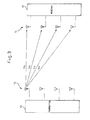
Figure 3 is a diagram explaining the case where transmissions from some of transmitting antennas are stopped; -
Figure 4 is a diagram explaining channel estimates for the case where transmissions from some of transmitting antennas are stopped; -
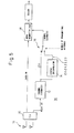
Figure 5 is a diagram showing the configuration of a receiver according to one embodiment of the present invention. - The following description is given by taking as an example a case where transmissions from three antennas are stopped in a system that transmits signals from four antennas and receives the signals by four antennas, but generally, the following description is applicable to a case where a transmission or transmissions from selected antenna or antennas are stopped in a system that transmits signals from a plurality of antennas and receives the signals by a plurality of antennas.
-
Figure 1 shows one example of an MIMO system to which the present invention is applied. Atransmitter 10 transmits different channel-coded data streams from four transmittingantennas 12 using the same frequency band. At the receiving end, the data streams are received by four receivingantennas 14; in areceiver 16, channel estimates that can be expressed in the form of a 4 x 4 matrix, whose elements consist of 16 complex numbers hij (i, j = 1 to 4) as shown inFigure 1 , are calculated by using pilot signals contained in the respective received data streams, and the received data channels are demultiplexed by using the channel estimates, to reconstruct the original data. -
Figure 2 shows one example of the frame format of the data transmitted from thetransmitter 10 to thereceiver 16. One frame consists of a data channel (CH) 20 and apilot CH 22 preceding it. In the pilot CH section, the pilot signals comprising mutually orthogonal codes (known patterns) from the respective transmitting antennas are received in multiplexed form by the respective receiving antennas; therefore, by taking correlation with each known pattern for each received signal, the complex number indicating the amplitude and phase of the pilot signal from each transmitting antenna is determined and, by dividing it by a predetermined value, the channel estimate hij is calculated. Then, an average value ξ0(n) taken between the channel estimate h(n) determined for the pilot CH in the n-th frame and the channel estimate h(n+1) determined for the pilot CH in the (n+1)th frame is used as the channel estimate ξ(n) that is used for channel demultiplexing of the data CH in the n-th frame (n). Such channel estimates ξ0(n) also comprise 16 complex numbers hij (i, j = 1 to 4) and can be expressed in the form of a 4 × 4 matrix having these complex numbers as the elements. - In the
receiver 16, computing resources are made available for each frame so that the computation for the channel demultiplexing using the channel estimates ξ0(n) completes within one frame period. - Here, if transmissions from three of the four transmitting antennas are stopped due to a degradation in SNIR, as shown in
Figure 3 , the channel estimates needed for the computation are only h11, h21, h31, and h41, and thus the amount of computation decreases, rendering some of the computing resources idle. - In view of this, in the present invention, as shown in
Figure 4 , the period of thedata CH 20 is divided into four sections, and the computation is performed using four different channel estimates ξ0(n), ξ1(n), ξ2(n), and ξ3(n) calculated for the respective sections by linear interpolation from h(n) and h(n+1). In other words, the data of N symbol intervals within one frame is divided into four parts, and the four different channel estimates are sequentially applied to the respective data of N/4 symbol intervals. This achieves highly accurate computation that can cope with fast fading by making effective use of the computing resources made available as a result of the number of transmitting antennas reduced due to a deterioration of the propagation environment. -
Figure 5 shows one configuration example of thereceiver 16 that implements the above process. Achannel estimator 32 calculates the channel estimate ξ0(n) from the amplitude and phase of the pilot signal contained in the received data in the pilot CH from among the data received by areceiving section 30, and alinear interpolator 34 calculates the channel estimates ξ0(n), ξ1(n), ξ2(n), and ξ3(n) by linear interpolation. Achannel estimate selector 36 selects the channel estimates ξ0(n), ξ1(n), ξ2(n), and ξ3(n) obtained by linear interpolation from adjacent channel estimates when the number of transmitting antennas is reduced to one, or otherwise selects the channel estimate ξ0(n) obtained by taking an average between the adjacent channel estimates, and supplies the selected channel estimates to anMIMO demultiplexer 38. Using the channel estimates selected by thechannel estimate selector 36, theMIMO demultiplexer 38 performs the channel demultiplexing by applying a demultiplexing algorithm, such as an MMSE (Minimum Mean Square Error) algorithm or an MLD (Maximum Likelihood Detection) algorithm, to the received data in the data CH period. - As the number of transmitting antennas that is used by the
channel estimate selector 36, use may be made of the number of transmitting antennas that is transmitted from the transmitting end over the control channel, or alternatively, the number of pilot signals detected by thechannel estimator 32 as having correlation greater than a threshold value with a known pattern may be used as the number of transmitting antennas.
Claims (5)
- An MIMO (Multi Input Multi Output) demodulator for performing channel demultiplexing of data transmitted from a plurality of transmitting antennas and received by a plurality of receiving antennas, comprising:a channel estimator calculating a channel estimate based on the received data;a channel estimate adjusting circuit changing, for the channel estimate calculated by the channel estimator, a range of data to which the same channel estimate is to be applied, based on the number of transmitting antennas used for transmitting the data; andan MIMO demultiplexer performing MIMO demultiplexing on the received data by using the channel estimate whose applicable data range has been adjusted by the channel estimate adjusting circuit.
- An MIMO demodulator according to claim 1, wherein when the number of transmitting antennas is reduced, the channel estimate adjusting circuit reduces the range of data to which the same channel estimate is to be applied.
- An MIMO demodulator according to claim 2, wherein the channel estimate adjusting circuit reduces the range of data to which the same channel estimate is to be applied, by linearly interpolating between the channel estimates calculated by the channel estimator.
- An MIMO demodulator according to claim 3, wherein the channel estimate adjusting circuit includes
a linear interpolation circuit linearly interpolating between the channel estimates output from the channel estimator, and
a channel estimate selector selecting one of the channel estimates output from the channel estimator and the channel estimates output from the linear interpolation circuit, depending on the number of transmitting antennas, and supplying the selected channel estimates to the MIMO demultiplexer. - An MIMO (Multi Input Multi Output) demodulation method for performing channel demultiplexing of data transmitted from a plurality of transmitting antennas and received by a plurality of receiving antennas, comprising:calculating a channel estimate based on the received data;changing, for the calculated channel estimate, a range of data to which the same channel estimate is to be applied, based on the number of transmitting antennas used for transmitting the data; andperforming MIMO demultiplexing on the received data by using the channel estimate whose applicable data range has been adjusted.
Applications Claiming Priority (1)
| Application Number | Priority Date | Filing Date | Title |
|---|---|---|---|
| PCT/JP2006/314424 WO2008010284A1 (en) | 2006-07-20 | 2006-07-20 | Mimo demodulator and method |
Publications (3)
| Publication Number | Publication Date |
|---|---|
| EP2045943A1 true EP2045943A1 (en) | 2009-04-08 |
| EP2045943A4 EP2045943A4 (en) | 2013-01-23 |
| EP2045943B1 EP2045943B1 (en) | 2016-08-17 |
Family
ID=38956621
Family Applications (1)
| Application Number | Title | Priority Date | Filing Date |
|---|---|---|---|
| EP06781379.0A Ceased EP2045943B1 (en) | 2006-07-20 | 2006-07-20 | MIMO receiver and method |
Country Status (4)
| Country | Link |
|---|---|
| US (1) | US8279961B2 (en) |
| EP (1) | EP2045943B1 (en) |
| JP (1) | JP4689722B2 (en) |
| WO (1) | WO2008010284A1 (en) |
Cited By (1)
| Publication number | Priority date | Publication date | Assignee | Title |
|---|---|---|---|---|
| EP2731288A4 (en) * | 2011-07-06 | 2015-04-01 | Fujitsu Ltd | BASE STATION, WIRELESS TERMINAL, CHANNEL VALUE ESTIMATING METHOD, PILOT SIGNAL TRANSMISSION METHOD, AND WIRELESS COMMUNICATION SYSTEM |
Families Citing this family (4)
| Publication number | Priority date | Publication date | Assignee | Title |
|---|---|---|---|---|
| US8428538B2 (en) * | 2008-07-09 | 2013-04-23 | Intel Mobile Communications GmbH | Channel estimator |
| EP2234354A1 (en) * | 2009-03-24 | 2010-09-29 | NTT DoCoMo, Inc. | A radio channel estimator exploiting correlations in space, frequency and time domain |
| US8548511B2 (en) * | 2010-06-21 | 2013-10-01 | Qualcomm Incorporated | Energy saving mode with maintained number of advertised transmit antennas |
| US8837621B2 (en) * | 2011-05-09 | 2014-09-16 | Telefonaktiebolaget L M Ericsson (Publ) | Channel estimation for a very large-scale multiple-input multiple output (MIMO) system |
Family Cites Families (7)
| Publication number | Priority date | Publication date | Assignee | Title |
|---|---|---|---|---|
| JP2748743B2 (en) * | 1991-10-01 | 1998-05-13 | 日本電気株式会社 | Data receiving method |
| DE19747457C2 (en) * | 1997-10-27 | 2000-04-06 | Siemens Ag | Method and arrangement for the transmission of data via a radio interface in a radio communication system |
| JP2001189768A (en) * | 1999-12-28 | 2001-07-10 | Matsushita Electric Ind Co Ltd | Synchronous detector |
| US20030012308A1 (en) * | 2001-06-13 | 2003-01-16 | Sampath Hemanth T. | Adaptive channel estimation for wireless systems |
| JP2003198426A (en) * | 2001-12-27 | 2003-07-11 | Mitsubishi Electric Corp | Adaptive modulation wireless communication device |
| JP2003332955A (en) * | 2002-05-17 | 2003-11-21 | Toshiba Corp | Radio transmitting apparatus and radio communication system |
| JP4668842B2 (en) * | 2006-05-26 | 2011-04-13 | ソフトバンクBb株式会社 | Wireless transmission system, transmitter, and wireless transmission method |
-
2006
- 2006-07-20 JP JP2008525763A patent/JP4689722B2/en not_active Expired - Fee Related
- 2006-07-20 EP EP06781379.0A patent/EP2045943B1/en not_active Ceased
- 2006-07-20 WO PCT/JP2006/314424 patent/WO2008010284A1/en not_active Ceased
-
2009
- 2009-01-21 US US12/357,206 patent/US8279961B2/en not_active Expired - Fee Related
Cited By (2)
| Publication number | Priority date | Publication date | Assignee | Title |
|---|---|---|---|---|
| EP2731288A4 (en) * | 2011-07-06 | 2015-04-01 | Fujitsu Ltd | BASE STATION, WIRELESS TERMINAL, CHANNEL VALUE ESTIMATING METHOD, PILOT SIGNAL TRANSMISSION METHOD, AND WIRELESS COMMUNICATION SYSTEM |
| US9220026B2 (en) | 2011-07-06 | 2015-12-22 | Fujitsu Limited | Base station, wireless terminal, and wireless communication system |
Also Published As
| Publication number | Publication date |
|---|---|
| EP2045943A4 (en) | 2013-01-23 |
| WO2008010284A1 (en) | 2008-01-24 |
| JPWO2008010284A1 (en) | 2009-12-17 |
| EP2045943B1 (en) | 2016-08-17 |
| JP4689722B2 (en) | 2011-05-25 |
| US8279961B2 (en) | 2012-10-02 |
| US20090129498A1 (en) | 2009-05-21 |
Similar Documents
| Publication | Publication Date | Title |
|---|---|---|
| TWI387233B (en) | A method for transmitting a signal in multi-antenna communication system | |
| EP1759470B1 (en) | Apparatus and method for beamforming in a multi-antenna system | |
| KR100817675B1 (en) | Transmitting method, receiving method, and radio apparatus using them | |
| US20050031062A1 (en) | Method and apparatus for determining a shuffling pattern based on a minimum signal to noise ratio in a double space-time transmit diversity system | |
| JP2007244002A (en) | Method and system for implementing smart antennas and diversity techniques | |
| WO2009002087A1 (en) | Method of transmitting feedback data in multiple antenna system | |
| KR20060048586A (en) | Transceiver using multiple antennas and transmission / reception method | |
| KR101106692B1 (en) | Apparatus and method for selecting operation mode of multi-input / output communication system | |
| JP4390636B2 (en) | OFDM signal frame generator, transmitter, signal transmission system, and OFDM signal frame generation method | |
| US8279961B2 (en) | MIMO demodulator and method for the same | |
| EP1912362B1 (en) | Communication device, and radio communication system | |
| US20090022239A1 (en) | Radio transmitter, radio receiver and symbol arranging method | |
| RU2583840C2 (en) | Device and method for uplink pilot signals for wcdma communication | |
| KR101460745B1 (en) | Apparatus and method for simultaneously supporting multiple input multiple output and beamforming in a wireless communication system | |
| US8374285B2 (en) | System and method for time domain interpolation of signals for channel estimation | |
| KR20080101014A (en) | Method and apparatus for predicting wireless channel in wireless communication system | |
| US8767579B2 (en) | Method of PCI and CQI estimation in CDMA systems | |
| KR101413937B1 (en) | Method and appratus selecting transmit antenna and estimating uplink multiple-input multiple-output channels in time-division multiplexing wireless communication systems | |
| EP2266243B1 (en) | Reduced complexity frequency band and virtual antenna combination selection | |
| CN100471086C (en) | A Method of Selecting Transmitting Antenna by Closed-loop Control in Multi-antenna System | |
| EP1892852B1 (en) | Device and method for controlling a selection of antennas in a wireless communication system | |
| US7676719B2 (en) | Transmitter apparatus and multiantenna transmitter apparatus | |
| JP4564430B2 (en) | COMMUNICATION DEVICE, COMMUNICATION METHOD, RADIO COMMUNICATION SYSTEM, AND RADIO COMMUNICATION METHOD | |
| KR101076756B1 (en) | Method and apparatus for adaptive receive signal decoding by chnnel variation in communication system | |
| KR101049113B1 (en) | Transmission Diversity Method of Mobile Communication System |
Legal Events
| Date | Code | Title | Description |
|---|---|---|---|
| PUAI | Public reference made under article 153(3) epc to a published international application that has entered the european phase |
Free format text: ORIGINAL CODE: 0009012 |
|
| 17P | Request for examination filed |
Effective date: 20090211 |
|
| AK | Designated contracting states |
Kind code of ref document: A1 Designated state(s): AT BE BG CH CY CZ DE DK EE ES FI FR GB GR HU IE IS IT LI LT LU LV MC NL PL PT RO SE SI SK TR |
|
| AX | Request for extension of the european patent |
Extension state: AL BA HR MK RS |
|
| RIC1 | Information provided on ipc code assigned before grant |
Ipc: H04J 99/00 20090101AFI20090407BHEP |
|
| RBV | Designated contracting states (corrected) |
Designated state(s): DE FR GB IT |
|
| DAX | Request for extension of the european patent (deleted) | ||
| A4 | Supplementary search report drawn up and despatched |
Effective date: 20130104 |
|
| RIC1 | Information provided on ipc code assigned before grant |
Ipc: H04L 25/02 20060101ALI20121220BHEP Ipc: H04J 99/00 20090101AFI20121220BHEP |
|
| REG | Reference to a national code |
Ref country code: DE Ref legal event code: R079 Ref document number: 602006049979 Country of ref document: DE Free format text: PREVIOUS MAIN CLASS: H04J0099000000 Ipc: H04L0025020000 |
|
| GRAP | Despatch of communication of intention to grant a patent |
Free format text: ORIGINAL CODE: EPIDOSNIGR1 |
|
| RIC1 | Information provided on ipc code assigned before grant |
Ipc: H04J 99/00 20090101ALI20160217BHEP Ipc: H04L 25/02 20060101AFI20160217BHEP |
|
| INTG | Intention to grant announced |
Effective date: 20160307 |
|
| GRAS | Grant fee paid |
Free format text: ORIGINAL CODE: EPIDOSNIGR3 |
|
| GRAA | (expected) grant |
Free format text: ORIGINAL CODE: 0009210 |
|
| AK | Designated contracting states |
Kind code of ref document: B1 Designated state(s): DE FR GB IT |
|
| REG | Reference to a national code |
Ref country code: GB Ref legal event code: FG4D |
|
| REG | Reference to a national code |
Ref country code: DE Ref legal event code: R096 Ref document number: 602006049979 Country of ref document: DE |
|
| REG | Reference to a national code |
Ref country code: DE Ref legal event code: R097 Ref document number: 602006049979 Country of ref document: DE |
|
| REG | Reference to a national code |
Ref country code: FR Ref legal event code: PLFP Year of fee payment: 12 |
|
| PLBE | No opposition filed within time limit |
Free format text: ORIGINAL CODE: 0009261 |
|
| STAA | Information on the status of an ep patent application or granted ep patent |
Free format text: STATUS: NO OPPOSITION FILED WITHIN TIME LIMIT |
|
| 26N | No opposition filed |
Effective date: 20170518 |
|
| PGFP | Annual fee paid to national office [announced via postgrant information from national office to epo] |
Ref country code: FR Payment date: 20170530 Year of fee payment: 12 Ref country code: GB Payment date: 20170503 Year of fee payment: 12 |
|
| PGFP | Annual fee paid to national office [announced via postgrant information from national office to epo] |
Ref country code: IT Payment date: 20170426 Year of fee payment: 12 |
|
| PGFP | Annual fee paid to national office [announced via postgrant information from national office to epo] |
Ref country code: DE Payment date: 20170412 Year of fee payment: 12 |
|
| REG | Reference to a national code |
Ref country code: DE Ref legal event code: R119 Ref document number: 602006049979 Country of ref document: DE |
|
| GBPC | Gb: european patent ceased through non-payment of renewal fee |
Effective date: 20180720 |
|
| PG25 | Lapsed in a contracting state [announced via postgrant information from national office to epo] |
Ref country code: DE Free format text: LAPSE BECAUSE OF NON-PAYMENT OF DUE FEES Effective date: 20190201 Ref country code: GB Free format text: LAPSE BECAUSE OF NON-PAYMENT OF DUE FEES Effective date: 20180720 Ref country code: FR Free format text: LAPSE BECAUSE OF NON-PAYMENT OF DUE FEES Effective date: 20180731 |
|
| PG25 | Lapsed in a contracting state [announced via postgrant information from national office to epo] |
Ref country code: IT Free format text: LAPSE BECAUSE OF NON-PAYMENT OF DUE FEES Effective date: 20180720 |