EP2045511B1 - Method and apparatus for lighting - Google Patents
Method and apparatus for lighting Download PDFInfo
- Publication number
- EP2045511B1 EP2045511B1 EP08165222A EP08165222A EP2045511B1 EP 2045511 B1 EP2045511 B1 EP 2045511B1 EP 08165222 A EP08165222 A EP 08165222A EP 08165222 A EP08165222 A EP 08165222A EP 2045511 B1 EP2045511 B1 EP 2045511B1
- Authority
- EP
- European Patent Office
- Prior art keywords
- fixture
- light source
- light
- grid
- disposed
- Prior art date
- Legal status (The legal status is an assumption and is not a legal conclusion. Google has not performed a legal analysis and makes no representation as to the accuracy of the status listed.)
- Not-in-force
Links
Images


Classifications
-
- F—MECHANICAL ENGINEERING; LIGHTING; HEATING; WEAPONS; BLASTING
- F21—LIGHTING
- F21V—FUNCTIONAL FEATURES OR DETAILS OF LIGHTING DEVICES OR SYSTEMS THEREOF; STRUCTURAL COMBINATIONS OF LIGHTING DEVICES WITH OTHER ARTICLES, NOT OTHERWISE PROVIDED FOR
- F21V11/00—Screens not covered by groups F21V1/00, F21V3/00, F21V7/00 or F21V9/00
- F21V11/08—Screens not covered by groups F21V1/00, F21V3/00, F21V7/00 or F21V9/00 using diaphragms containing one or more apertures
- F21V11/12—Screens not covered by groups F21V1/00, F21V3/00, F21V7/00 or F21V9/00 using diaphragms containing one or more apertures of slot type
-
- F—MECHANICAL ENGINEERING; LIGHTING; HEATING; WEAPONS; BLASTING
- F21—LIGHTING
- F21S—NON-PORTABLE LIGHTING DEVICES; SYSTEMS THEREOF; VEHICLE LIGHTING DEVICES SPECIALLY ADAPTED FOR VEHICLE EXTERIORS
- F21S8/00—Lighting devices intended for fixed installation
- F21S8/03—Lighting devices intended for fixed installation of surface-mounted type
- F21S8/033—Lighting devices intended for fixed installation of surface-mounted type the surface being a wall or like vertical structure, e.g. building facade
- F21S8/035—Lighting devices intended for fixed installation of surface-mounted type the surface being a wall or like vertical structure, e.g. building facade by means of plugging into a wall outlet, e.g. night light
-
- F—MECHANICAL ENGINEERING; LIGHTING; HEATING; WEAPONS; BLASTING
- F21—LIGHTING
- F21W—INDEXING SCHEME ASSOCIATED WITH SUBCLASSES F21K, F21L, F21S and F21V, RELATING TO USES OR APPLICATIONS OF LIGHTING DEVICES OR SYSTEMS
- F21W2131/00—Use or application of lighting devices or systems not provided for in codes F21W2102/00-F21W2121/00
- F21W2131/10—Outdoor lighting
- F21W2131/103—Outdoor lighting of streets or roads
-
- F—MECHANICAL ENGINEERING; LIGHTING; HEATING; WEAPONS; BLASTING
- F21—LIGHTING
- F21W—INDEXING SCHEME ASSOCIATED WITH SUBCLASSES F21K, F21L, F21S and F21V, RELATING TO USES OR APPLICATIONS OF LIGHTING DEVICES OR SYSTEMS
- F21W2131/00—Use or application of lighting devices or systems not provided for in codes F21W2102/00-F21W2121/00
- F21W2131/10—Outdoor lighting
- F21W2131/109—Outdoor lighting of gardens
-
- F—MECHANICAL ENGINEERING; LIGHTING; HEATING; WEAPONS; BLASTING
- F21—LIGHTING
- F21Y—INDEXING SCHEME ASSOCIATED WITH SUBCLASSES F21K, F21L, F21S and F21V, RELATING TO THE FORM OR THE KIND OF THE LIGHT SOURCES OR OF THE COLOUR OF THE LIGHT EMITTED
- F21Y2113/00—Combination of light sources
-
- F—MECHANICAL ENGINEERING; LIGHTING; HEATING; WEAPONS; BLASTING
- F21—LIGHTING
- F21Y—INDEXING SCHEME ASSOCIATED WITH SUBCLASSES F21K, F21L, F21S and F21V, RELATING TO THE FORM OR THE KIND OF THE LIGHT SOURCES OR OF THE COLOUR OF THE LIGHT EMITTED
- F21Y2115/00—Light-generating elements of semiconductor light sources
- F21Y2115/10—Light-emitting diodes [LED]
-
- Y—GENERAL TAGGING OF NEW TECHNOLOGICAL DEVELOPMENTS; GENERAL TAGGING OF CROSS-SECTIONAL TECHNOLOGIES SPANNING OVER SEVERAL SECTIONS OF THE IPC; TECHNICAL SUBJECTS COVERED BY FORMER USPC CROSS-REFERENCE ART COLLECTIONS [XRACs] AND DIGESTS
- Y10—TECHNICAL SUBJECTS COVERED BY FORMER USPC
- Y10S—TECHNICAL SUBJECTS COVERED BY FORMER USPC CROSS-REFERENCE ART COLLECTIONS [XRACs] AND DIGESTS
- Y10S362/00—Illumination
- Y10S362/806—Ornamental or decorative
Definitions
- the present invention is related to a lighting apparatus having multiple lighting sources for functionality as well as decorative lighting. More specifically, the present invention is related to a lighting apparatus having multiple lighting sources for functionality as well as decorative lighting that uses a grid to reflect light and LEDs.
- municipalities and or private individuals will add colored strings of lights to their existing outdoor lighting fixtures for holidays such as Christmas, New Year, etc. and for other occasions such as weddings, baptisms and bar mitzvahs, etc.
- the present invention will provide the opportunity of having functional light all the time and the ability to use the secondary source for festive purposes.
- FR 2897414 A1 discloses a lantern comprising a principal light and a secondary light which are operated alternately.
- the principal light is located within a light distributor which diffuses the light.
- the secondary light is provided by a plurality of LEDs which are located around the circumference of a cap that is connected to a base on which the principal light is mounted.
- JP 2004247157 discloses a luminaire having first and second light sources.
- the first light source comprises an LED lamp which is activated when the light conditions are below a threshold value.
- the second light source comprises a fluorescent lamp which is connected to a motion sensor and is activated from the motion of an approaching person.
- the present invention pertains to an apparatus for lighting.
- the apparatus comprises a fixture having a central axis.
- the apparatus comprises a first light source disposed in the fixture which produces light along the center axis.
- the apparatus comprises a grid having slots which reflect the light radially outward from the center axis extending from the fixture along the center axis and illuminated by the first light source.
- the apparatus comprises a translucent element extending from the fixture along the center axis and disposed about and in spaced relationship with the grid.
- the apparatus comprises a second light source disposed between the element and the grid.
- the first light source is recessed in the fixture at the fixture's top so the first light source itself is not visible by locking at the apparatus sideways.
- the present invention pertains to a method for lighting.
- the method comprises the steps of producing light along a center axis of a fixture with a first light source disposed in the fixture.
- the first light source is recessed in the fixture at the fixture's top so the first light source itself is not visible by looking at the apparatus sideways.
- Figure 1 shows a cutaway view of the apparatus of the present invention.
- Figure 2 is an alternative embodiment of the apparatus.
- Figure 3 is a perspective cutaway view of the apparatus.
- Figure 4 is a side view of the apparatus.
- Figure 5 is a cutaway view of another embodiment of the apparatus.
- Figure 6 is a perspective cutaway view of another embodiment of the apparatus.
- Figure 7 shows a circular array of individual LEDs, projecting light vertically along the grid.
- Figure 8 shows a ring shaped printed circuit board containing a circular array of LEDs, projecting light along the grid.
- Figure 9 shows a flexible LED strip, arranged in a circular shape, projecting light vertically along the grid.
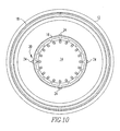
- Figure 10 shows a circular array of LED strips, vertically mounted against the grid, projecting light horizontally towards the transparent element.
- the apparatus 10 comprises a fixture 12 having a central axis 28.
- the apparatus 10 comprises a first light source 14 disposed in the fixture 12 which produces light along the center axis 28.
- the apparatus 10 comprises a grid 16 having slots which reflect the light radially outward from the center axis extending from the fixture 12 along the center axis 28 and illuminated by the first light source 14.
- the apparatus 10 comprises a translucent element 18 extending from the fixture 12 along the center axis and disposed about and in spaced relationship with the grid 16.
- the apparatus 10 comprises a second light source 20 disposed between the element and the grid 16.
- Figure 2 shows an embodiment where the first light source 14 is a fluorescent light that extends from the fixture 12 upwards along the center axis 28.
- the apparatus 10 includes a cap 22 disposed on the elements and the grid 16.
- the cap 22 can have one of more mirrors 34 which reflect the light from the first light source 14.
- the second light source 20 preferably includes LEDs 24.
- the fixture 12 is hollow and contains wiring to operate the first and second light sources 14, 20.
- the fixture 12 preferably includes circuitry to control the operation of the first and second light sources 14, 20.
- the apparatus 10 includes a third light source disposed in the fixture 12, and wherein the fixture 12 has an opening 30 in its side through which light from the third source 26 emanates, as shown in figure 5 .
- the first light source 14 is recessed in the fixture 12 at the fixture's top so the first light source 14 itself is not visible by looking at the apparatus 10 sideways.
- the LEDs 24 can extend along the central axis 28 as shown in figures 6 and 10 .
- the LEDs 24 can be disposed radially about the first light source 14, as shown in figures 7-9 .
- the fixture 12, element and the grid 16 are cylindrically shaped.
- the present invention pertains to a method for lighting.
- the method comprises the steps of producing light along a center axis 28 of a fixture 12 with a first light source 14 disposed in the fixture 12.
- a first light source 14 disposed in the fixture 12.
- a grid 16 having slots extending from the fixture 12 along the center axis and illuminated by the first light source 14.
- the producing the light with the second light source 20 includes the step of producing the light with LEDs 24. There is the step of controlling the first light source 14 and the LEDs 24 with circuitry to cause a desired lighting effect.
- the apparatus 10 can be used for indoor and outdoor lighting.
- the concept is based upon the use of multiple light sources within a fixture 12.
- the use of multiple sources provides the opportunity of providing one source of light for utilitarian illumination that is required to meet specific lighting requirements.
- the second source is to add sparkle to the fixture's 12 general appearance or provide soft low levels of visually comfortable illumination.
- a third source 26 (for downlighting) if used can provide walkway, night lighting, ground covering or plant illumination.
- the construction of the fixture 12, whatever the mounting method, can be round or square, made of many different materials such as stainless steel, aluminum, steel, wood, granite, marble, stone, plastics or synthetic composites.
- One of the sources is mounted in the center of the enclosure and projects light upward, as shown in figures 1-4 .
- a tubular element, square or round, is placed on the outside diameter of the center source and is illuminated by this source.
- This tubular element can be grid 16 in structure, polished or brushed, and made of stainless steel, aluminum or any other metallic or non-metallic materials. It will reflect light outward and upward or downward and outward or depending upon the angular cut upward only or downward only.
- the grid 16 effectively has over a hundred slots to reflect light.
- a second source will be placed outside the grid 16 between the grid 16 and the outer tubular, cylindrical or square plastic, glass, granite, marble, etc. to complete the structural integrity of the luminare.
- An o-ring joint 32 is used to hold the element 18 to the fixture 12.
- the center source can be line voltage incandescent, low voltage halogen, metal halide or compact fluorescent or tubular T2, T5 fluorescent or cold cathode.
- the second source can be LEDs 24. All of the LEDs 24 can be one color or mixed colors. Color mixing, blending, sequencing and chasing is possible. Multiple circuiting for the various color LEDs 24 is also possible. Dimming, color changing is also possible.
- This second source will reflect light off of the tubular grid 16 and be visible through the outer tubular cylindrical or square tubular plastic (acrylic, polycarbonate, etc.) translucent element 18. If marble, granite, stone is used as the exterior element, it can be secured in a manner so that it appears to be floating (free of being visibly held from the bottom of the top of the fixture 12) so that light is emitted between the bottom of the outer structural element and the top of the outer structural element.
- the LEDs 24 can be individual and mounted around the circumference of the grid 16, as shown in figure 7 .
- the LEDs 24 can also be mounted on a PC board in a circular pattern, as shown in figure 8 .
- the LEDs 24 can be mounted on a soft strip which can be formed in a circular pattern for horizontal mounting or in a linear pattern for horizontal mounting or vertical mounting, as shown in figure 9 .
- the LED's soft strip can be placed against the exterior of the gird, as shown in figure 10 .
- the number of vertical LED 24 soft strips can vary from one to twenty +/- depending upon the desired results.
- the LEDs 24 could also be placed on the interior of the grid 16.
- the sources can be inter-changed LEDs 24 used for the center source and metal halide, PL or T2 T5 fluorescent lamps can be used for the inner source.
- a third source 26 can be mounted in the fixture 12 structure and used with or without a reflector for downlight, as shown in figure 5 .
- the reflector can be aluminum, polished or satin, anodized and/or painted.
- the reflector can also be made of steel and/or glass and properly coated and treated to provide the desired and required effects for walkway, night lighting, and ground cover illuminations.
- Each source can be individually switched and/or circuited, dimmed and/or sequenced and/or chased.
- the finish of the fixture 12 structure can be polished or satin stainless or anodized or duronodic if made of aluminum, it can be painted irrespective of which metal is used for the construction. If the construction is marble, granite, stone, etc., the finishes can be appropriate to the material used.
- the fixture 12 can be wall surface mounted for uplight and/or uplight/downlight. They can be mounted above ground for low level (6-18" (15-46cm) height), medium level (18"-40" (46-102cm) height), walkway (residential or commercial) (40"-96" (102-244cm) height), campus lighting (96"-168" (244-427cm) height) or for parking lot or area lighting where the mounting height might be 20'-30' (6-12m) or more.
- the fixture 12 can be free standing and the fixture 12 can be mounted to a ceiling and extend downward or to a wall and extend horizontally relative to the ground from the wall.
- the grid 16 material whether polished stainless or satin stainless steel is readily available from manufacturers of grating or screen companies.
- One such manufacture is Hendrick Screen Co.
Description
- The present invention is related to a lighting apparatus having multiple lighting sources for functionality as well as decorative lighting. More specifically, the present invention is related to a lighting apparatus having multiple lighting sources for functionality as well as decorative lighting that uses a grid to reflect light and LEDs.
- Historically, in different countries during different time of the year for festive purposes, municipalities and or private individuals will add colored strings of lights to their existing outdoor lighting fixtures for holidays such as Christmas, New Year, etc. and for other occasions such as weddings, baptisms and bar mitzvahs, etc.
- The present invention will provide the opportunity of having functional light all the time and the ability to use the secondary source for festive purposes.
-
FR 2897414 A1 -
JP 2004247157 - The present invention pertains to an apparatus for lighting. The apparatus comprises a fixture having a central axis. The apparatus comprises a first light source disposed in the fixture which produces light along the center axis. The apparatus comprises a grid having slots which reflect the light radially outward from the center axis extending from the fixture along the center axis and illuminated by the first light source. The apparatus comprises a translucent element extending from the fixture along the center axis and disposed about and in spaced relationship with the grid. The apparatus comprises a second light source disposed between the element and the grid. The first light source is recessed in the fixture at the fixture's top so the first light source itself is not visible by locking at the apparatus sideways.
- The present invention pertains to a method for lighting. The method comprises the steps of producing light along a center axis of a fixture with a first light source disposed in the fixture. There is the step of reflecting the light radially outward from the center axis with a grid having slots extending from the fixture along the center axis and illuminated by the first light source. There is the step of transmitting the light through a translucent element extending from the fixture along the center axis and disposed about and in spaced relationship with the grid. There is the step of producing light with a second light source disposed between the element and the grid. The first light source is recessed in the fixture at the fixture's top so the first light source itself is not visible by looking at the apparatus sideways.
- In the accompanying drawings, the preferred embodiment of the invention and preferred methods of practicing the invention are illustrated in which:
-
Figure 1 shows a cutaway view of the apparatus of the present invention. -
Figure 2 is an alternative embodiment of the apparatus. -
Figure 3 is a perspective cutaway view of the apparatus. -
Figure 4 is a side view of the apparatus. -
Figure 5 is a cutaway view of another embodiment of the apparatus. -
Figure 6 is a perspective cutaway view of another embodiment of the apparatus. -
Figure 7 shows a circular array of individual LEDs, projecting light vertically along the grid. -
Figure 8 shows a ring shaped printed circuit board containing a circular array of LEDs, projecting light along the grid. -
Figure 9 shows a flexible LED strip, arranged in a circular shape, projecting light vertically along the grid. -
Figure 10 shows a circular array of LED strips, vertically mounted against the grid, projecting light horizontally towards the transparent element. - Referring now to the drawings wherein like reference numerals refer to similar or identical parts throughout the several views, and more specifically to
figures 1-4 thereof, there is shown anapparatus 10 for lighting. Theapparatus 10 comprises afixture 12 having acentral axis 28. Theapparatus 10 comprises afirst light source 14 disposed in thefixture 12 which produces light along thecenter axis 28. Theapparatus 10 comprises agrid 16 having slots which reflect the light radially outward from the center axis extending from thefixture 12 along thecenter axis 28 and illuminated by thefirst light source 14. Theapparatus 10 comprises atranslucent element 18 extending from thefixture 12 along the center axis and disposed about and in spaced relationship with thegrid 16. Theapparatus 10 comprises asecond light source 20 disposed between the element and thegrid 16.Figure 2 shows an embodiment where thefirst light source 14 is a fluorescent light that extends from thefixture 12 upwards along thecenter axis 28. - Preferably, the
apparatus 10 includes acap 22 disposed on the elements and thegrid 16. Thecap 22 can have one ofmore mirrors 34 which reflect the light from thefirst light source 14. Thesecond light source 20 preferably includesLEDs 24. Preferably, thefixture 12 is hollow and contains wiring to operate the first andsecond light sources fixture 12 preferably includes circuitry to control the operation of the first andsecond light sources apparatus 10 includes a third light source disposed in thefixture 12, and wherein thefixture 12 has anopening 30 in its side through which light from thethird source 26 emanates, as shown infigure 5 . Thefirst light source 14 is recessed in thefixture 12 at the fixture's top so thefirst light source 14 itself is not visible by looking at theapparatus 10 sideways. - The
LEDs 24 can extend along thecentral axis 28 as shown infigures 6 and10 . TheLEDs 24 can be disposed radially about thefirst light source 14, as shown infigures 7-9 . Preferably, thefixture 12, element and thegrid 16 are cylindrically shaped. - The present invention pertains to a method for lighting. The method comprises the steps of producing light along a
center axis 28 of afixture 12 with afirst light source 14 disposed in thefixture 12. There is the step of reflecting the light radially outward from thecenter axis 28 with agrid 16 having slots extending from thefixture 12 along the center axis and illuminated by thefirst light source 14. There is the step of transmitting the light through atranslucent element 18 extending from thefixture 12 along the center axis and disposed about and in spaced relationship with thegrid 16. There is the step of producing light with asecond light source 20 disposed between the element and thegrid 16. - Preferably, the producing the light with the
second light source 20 includes the step of producing the light withLEDs 24. There is the step of controlling thefirst light source 14 and theLEDs 24 with circuitry to cause a desired lighting effect. - The
apparatus 10 can be used for indoor and outdoor lighting. The concept is based upon the use of multiple light sources within afixture 12. The use of multiple sources provides the opportunity of providing one source of light for utilitarian illumination that is required to meet specific lighting requirements. The second source is to add sparkle to the fixture's 12 general appearance or provide soft low levels of visually comfortable illumination. A third source 26 (for downlighting) if used can provide walkway, night lighting, ground covering or plant illumination. - The construction of the
fixture 12, whatever the mounting method, can be round or square, made of many different materials such as stainless steel, aluminum, steel, wood, granite, marble, stone, plastics or synthetic composites. - One of the sources is mounted in the center of the enclosure and projects light upward, as shown in
figures 1-4 . A tubular element, square or round, is placed on the outside diameter of the center source and is illuminated by this source. This tubular element can begrid 16 in structure, polished or brushed, and made of stainless steel, aluminum or any other metallic or non-metallic materials. It will reflect light outward and upward or downward and outward or depending upon the angular cut upward only or downward only. Thegrid 16 effectively has over a hundred slots to reflect light. A second source will be placed outside thegrid 16 between thegrid 16 and the outer tubular, cylindrical or square plastic, glass, granite, marble, etc. to complete the structural integrity of the luminare. An o-ring joint 32 is used to hold theelement 18 to thefixture 12. - The center source can be line voltage incandescent, low voltage halogen, metal halide or compact fluorescent or tubular T2, T5 fluorescent or cold cathode.
- The second source can be
LEDs 24. All of theLEDs 24 can be one color or mixed colors. Color mixing, blending, sequencing and chasing is possible. Multiple circuiting for thevarious color LEDs 24 is also possible. Dimming, color changing is also possible. This second source will reflect light off of thetubular grid 16 and be visible through the outer tubular cylindrical or square tubular plastic (acrylic, polycarbonate, etc.)translucent element 18. If marble, granite, stone is used as the exterior element, it can be secured in a manner so that it appears to be floating (free of being visibly held from the bottom of the top of the fixture 12) so that light is emitted between the bottom of the outer structural element and the top of the outer structural element. TheLEDs 24 can be individual and mounted around the circumference of thegrid 16, as shown infigure 7 . TheLEDs 24 can also be mounted on a PC board in a circular pattern, as shown infigure 8 . TheLEDs 24 can be mounted on a soft strip which can be formed in a circular pattern for horizontal mounting or in a linear pattern for horizontal mounting or vertical mounting, as shown infigure 9 . For vertical mounting, the LED's soft strip can be placed against the exterior of the gird, as shown infigure 10 . The number ofvertical LED 24 soft strips can vary from one to twenty +/- depending upon the desired results. TheLEDs 24 could also be placed on the interior of thegrid 16. - It is also possible to have two lamps within the center section of the luminare, one lamp mounted beneath the other. The top lamp is mounted in the center to illuminate the interior of the
grid 16, the lower lamp (beneath the top lamp) with the use of the proper reflectors would be used to illuminate the space between thegrid 16 and the outside plastic diffuser and/or stone, marble etc. - The sources can be
inter-changed LEDs 24 used for the center source and metal halide, PL or T2 T5 fluorescent lamps can be used for the inner source. - A
third source 26 can be mounted in thefixture 12 structure and used with or without a reflector for downlight, as shown infigure 5 . The reflector can be aluminum, polished or satin, anodized and/or painted. The reflector can also be made of steel and/or glass and properly coated and treated to provide the desired and required effects for walkway, night lighting, and ground cover illuminations. - Each source can be individually switched and/or circuited, dimmed and/or sequenced and/or chased.
- The finish of the
fixture 12 structure can be polished or satin stainless or anodized or duronodic if made of aluminum, it can be painted irrespective of which metal is used for the construction. If the construction is marble, granite, stone, etc., the finishes can be appropriate to the material used. - The
fixture 12 can be wall surface mounted for uplight and/or uplight/downlight. They can be mounted above ground for low level (6-18" (15-46cm) height), medium level (18"-40" (46-102cm) height), walkway (residential or commercial) (40"-96" (102-244cm) height), campus lighting (96"-168" (244-427cm) height) or for parking lot or area lighting where the mounting height might be 20'-30' (6-12m) or more. Thefixture 12 can be free standing and thefixture 12 can be mounted to a ceiling and extend downward or to a wall and extend horizontally relative to the ground from the wall. - The
grid 16 material whether polished stainless or satin stainless steel is readily available from manufacturers of grating or screen companies. One such manufacture is Hendrick Screen Co.
Claims (12)
- An apparatus (10) for lighting comprising:a fixture (12) having a central axis (28);a first light source (14) disposed in the fixture (12) which produces light along the center axis (28) ; anda second light source (20); anda grid (16) having slots which reflect the light radially outward from the center axis (28) extending from the fixture (12) along the center axis (28) and illuminated by the first light source (14); andcharacterized by:a translucent element (18) extending from the fixture (12) along the center axis (28) and disposed about and in spaced relationship with the grid (16); andthe second light source (20) being disposed between the element (18) and the grid (16);wherein the first light source (14) is recessed in the fixture (12) at the fixture's top so the first light source (14) itself is not visible by looking at the apparatus (10) sideways.
- An apparatus (10) as described in Claim 1 including a cap (22) disposed on the elements and the grid (16).
- An apparatus (10) as described in Claim 1 or 2 wherein the second light source (20) includes LEDs (24).
- An apparatus (10) as described in any one of the preceding claims, wherein the fixture (12) includes circuitry to control the operation of the first and second light sources (14, 20).
- An apparatus (10) as described in any one of the preceding claims, including a third light source (26) disposed in the fixture (12), and wherein the fixture (12) has an opening (30) in its side through which light from the third source (26) emanates.
- An apparatus (10) as described in any one of the preceding claims, when appendant to claim 3, wherein the LEDs (24) extend along the central axis (28).
- An apparatus (10) as described in any one of the preceding claims, when appendant to claim 3, wherein the LEDs (24) are disposed radially about the first light source (14).
- An apparatus (10) as described in any one of the preceding claims, wherein the fixture (12), element (18) and the grid (16) are cylindrically shaped.
- An apparatus (10) as described in any one of the preceding claims when appendant to claim 2, wherein the cap (22) has at least one mirror (34) to reflect light from the first light source (14).
- A method for lighting comprising the steps of:producing light along a center axis (28) of a fixture (12) with a first light source (14) disposed in the fixture (12); and with a second light source (20); andreflecting the light radially outward from the center axis (28) with a grid (16) having slots extending from the fixture (12) along the center axis (28) and illuminated by the first light source (14); andcharacterized by:transmitting the light through a translucent element (18) extending from the fixture (12) along the center axis (28) and disposed about and in spaced relationship with the grid (16) ; andsaid second light source (20) being disposed between the element (18) and the grid (16);wherein the first light source (14) is recessed in the fixture (12) at the fixture's top so the first light source (14) itself is not visible by looking at the apparatus (10) sideways.
- A method as described in Claim 10 wherein the producing the light with the second light source (20) includes the step of producing the light with LEDs (24).
- A method as described in Claim 11 including the step of controlling the first light source (14) and the LEDs (24) with circuitry to cause a desired lighting effect.
Applications Claiming Priority (1)
| Application Number | Priority Date | Filing Date | Title |
|---|---|---|---|
| US11/906,560 US7478921B1 (en) | 2007-10-03 | 2007-10-03 | Method and apparatus for lighting |
Publications (2)
| Publication Number | Publication Date |
|---|---|
| EP2045511A1 EP2045511A1 (en) | 2009-04-08 |
| EP2045511B1 true EP2045511B1 (en) | 2013-01-02 |
Family
ID=40091835
Family Applications (1)
| Application Number | Title | Priority Date | Filing Date |
|---|---|---|---|
| EP08165222A Not-in-force EP2045511B1 (en) | 2007-10-03 | 2008-09-26 | Method and apparatus for lighting |
Country Status (2)
| Country | Link |
|---|---|
| US (1) | US7478921B1 (en) |
| EP (1) | EP2045511B1 (en) |
Families Citing this family (2)
| Publication number | Priority date | Publication date | Assignee | Title |
|---|---|---|---|---|
| ITBO20090186A1 (en) * | 2009-03-26 | 2009-06-25 | Vito Ferrigni | LIGHTING DEVICE |
| USD816878S1 (en) * | 2016-01-18 | 2018-05-01 | Philips Lighting Holding B.V. | Luminaire |
Family Cites Families (6)
| Publication number | Priority date | Publication date | Assignee | Title |
|---|---|---|---|---|
| JP3832556B2 (en) * | 2000-02-25 | 2006-10-11 | 株式会社安川電機 | Canned linear motor |
| JP4313056B2 (en) | 2003-02-13 | 2009-08-12 | 小泉産業株式会社 | lighting equipment |
| US6948830B1 (en) * | 2004-01-14 | 2005-09-27 | Petrick John T | Dual beacon obstruction lighting system |
| CN101018978A (en) * | 2004-09-14 | 2007-08-15 | 皇家飞利浦电子股份有限公司 | Luminaire with louver members |
| US7121678B1 (en) * | 2005-06-27 | 2006-10-17 | Shetter Edwin E | Portable emergency light |
| FR2897414B1 (en) | 2006-02-13 | 2008-07-11 | Pascal Michonneau | DEVICE FOR THE USE OF A RESIDENTIAL OR PUBLIC LIGHTING LANTERN IN OPTICAL DUAL VERSION FOR DISCHARGE LAMPS AND LED LAMPS WITH TIMED INVERTER RELAY. |
-
2007
- 2007-10-03 US US11/906,560 patent/US7478921B1/en not_active Expired - Fee Related
-
2008
- 2008-09-26 EP EP08165222A patent/EP2045511B1/en not_active Not-in-force
Also Published As
| Publication number | Publication date |
|---|---|
| EP2045511A1 (en) | 2009-04-08 |
| US7478921B1 (en) | 2009-01-20 |
Similar Documents
| Publication | Publication Date | Title |
|---|---|---|
| US7014341B2 (en) | Decorative luminaires | |
| JP5020725B2 (en) | Street lighting fixtures and street lights | |
| FI100205B (en) | Lighting fixture for a flagpole | |
| US10054275B2 (en) | Lighting apparatus | |
| NZ520431A (en) | Lamp | |
| KR100961726B1 (en) | Lighting device using led | |
| CN101018978A (en) | Luminaire with louver members | |
| KR100884628B1 (en) | Illuminator of using light emitting diode | |
| EP2045511B1 (en) | Method and apparatus for lighting | |
| KR200439900Y1 (en) | Fixing apparatus for a lighting | |
| US20050213316A1 (en) | Illuminated post system | |
| KR100898415B1 (en) | Ceiling lamp having decorative sub lighting comprising led and crystal reflector | |
| KR100973917B1 (en) | Decoration of cover for lamp | |
| US20040027827A1 (en) | Illuminated fans & light fixtures | |
| US20180328555A1 (en) | Light-emitting birdbath basin and integrated light-emitting birdbath basin | |
| US11608948B1 (en) | Light-and-shadow table lamp structure | |
| JP4491327B2 (en) | lighting equipment | |
| KR200468543Y1 (en) | Led lamp of two colors a light | |
| CN203082810U (en) | Lamp capable of being disassembled and assembled | |
| KR100715285B1 (en) | Led lamp | |
| US2222319A (en) | Luminaire | |
| US20080049427A1 (en) | Multicolored lighting fixture | |
| CN212841106U (en) | LED ceiling lamp | |
| KR101553523B1 (en) | Interior ceiling lights | |
| CN214663990U (en) | Indoor lighting device for simulating sky |
Legal Events
| Date | Code | Title | Description |
|---|---|---|---|
| PUAI | Public reference made under article 153(3) epc to a published international application that has entered the european phase |
Free format text: ORIGINAL CODE: 0009012 |
|
| AK | Designated contracting states |
Kind code of ref document: A1 Designated state(s): AT BE BG CH CY CZ DE DK EE ES FI FR GB GR HR HU IE IS IT LI LT LU LV MC MT NL NO PL PT RO SE SI SK TR |
|
| AX | Request for extension of the european patent |
Extension state: AL BA MK RS |
|
| 17P | Request for examination filed |
Effective date: 20091005 |
|
| 17Q | First examination report despatched |
Effective date: 20091030 |
|
| AKX | Designation fees paid |
Designated state(s): AT BE BG CH CY CZ DE DK EE ES FI FR GB GR HR HU IE IS IT LI LT LU LV MC MT NL NO PL PT RO SE SI SK TR |
|
| GRAP | Despatch of communication of intention to grant a patent |
Free format text: ORIGINAL CODE: EPIDOSNIGR1 |
|
| GRAS | Grant fee paid |
Free format text: ORIGINAL CODE: EPIDOSNIGR3 |
|
| GRAA | (expected) grant |
Free format text: ORIGINAL CODE: 0009210 |
|
| AK | Designated contracting states |
Kind code of ref document: B1 Designated state(s): AT BE BG CH CY CZ DE DK EE ES FI FR GB GR HR HU IE IS IT LI LT LU LV MC MT NL NO PL PT RO SE SI SK TR |
|
| REG | Reference to a national code |
Ref country code: GB Ref legal event code: FG4D |
|
| REG | Reference to a national code |
Ref country code: AT Ref legal event code: REF Ref document number: 591820 Country of ref document: AT Kind code of ref document: T Effective date: 20130115 Ref country code: CH Ref legal event code: EP |
|
| REG | Reference to a national code |
Ref country code: IE Ref legal event code: FG4D |
|
| REG | Reference to a national code |
Ref country code: DE Ref legal event code: R096 Ref document number: 602008021300 Country of ref document: DE Effective date: 20130228 |
|
| REG | Reference to a national code |
Ref country code: CH Ref legal event code: NV Representative=s name: DR. LUSUARDI AG, CH |
|
| REG | Reference to a national code |
Ref country code: AT Ref legal event code: MK05 Ref document number: 591820 Country of ref document: AT Kind code of ref document: T Effective date: 20130102 |
|
| REG | Reference to a national code |
Ref country code: NL Ref legal event code: VDEP Effective date: 20130102 |
|
| PG25 | Lapsed in a contracting state [announced via postgrant information from national office to epo] |
Ref country code: SI Free format text: LAPSE BECAUSE OF FAILURE TO SUBMIT A TRANSLATION OF THE DESCRIPTION OR TO PAY THE FEE WITHIN THE PRESCRIBED TIME-LIMIT Effective date: 20130102 |
|
| REG | Reference to a national code |
Ref country code: LT Ref legal event code: MG4D |
|
| PG25 | Lapsed in a contracting state [announced via postgrant information from national office to epo] |
Ref country code: BG Free format text: LAPSE BECAUSE OF FAILURE TO SUBMIT A TRANSLATION OF THE DESCRIPTION OR TO PAY THE FEE WITHIN THE PRESCRIBED TIME-LIMIT Effective date: 20130402 Ref country code: AT Free format text: LAPSE BECAUSE OF FAILURE TO SUBMIT A TRANSLATION OF THE DESCRIPTION OR TO PAY THE FEE WITHIN THE PRESCRIBED TIME-LIMIT Effective date: 20130102 Ref country code: CZ Free format text: LAPSE BECAUSE OF FAILURE TO SUBMIT A TRANSLATION OF THE DESCRIPTION OR TO PAY THE FEE WITHIN THE PRESCRIBED TIME-LIMIT Effective date: 20130102 Ref country code: ES Free format text: LAPSE BECAUSE OF FAILURE TO SUBMIT A TRANSLATION OF THE DESCRIPTION OR TO PAY THE FEE WITHIN THE PRESCRIBED TIME-LIMIT Effective date: 20130413 Ref country code: LT Free format text: LAPSE BECAUSE OF FAILURE TO SUBMIT A TRANSLATION OF THE DESCRIPTION OR TO PAY THE FEE WITHIN THE PRESCRIBED TIME-LIMIT Effective date: 20130102 Ref country code: SE Free format text: LAPSE BECAUSE OF FAILURE TO SUBMIT A TRANSLATION OF THE DESCRIPTION OR TO PAY THE FEE WITHIN THE PRESCRIBED TIME-LIMIT Effective date: 20130102 Ref country code: NO Free format text: LAPSE BECAUSE OF FAILURE TO SUBMIT A TRANSLATION OF THE DESCRIPTION OR TO PAY THE FEE WITHIN THE PRESCRIBED TIME-LIMIT Effective date: 20130402 Ref country code: IS Free format text: LAPSE BECAUSE OF FAILURE TO SUBMIT A TRANSLATION OF THE DESCRIPTION OR TO PAY THE FEE WITHIN THE PRESCRIBED TIME-LIMIT Effective date: 20130502 |
|
| PG25 | Lapsed in a contracting state [announced via postgrant information from national office to epo] |
Ref country code: LV Free format text: LAPSE BECAUSE OF FAILURE TO SUBMIT A TRANSLATION OF THE DESCRIPTION OR TO PAY THE FEE WITHIN THE PRESCRIBED TIME-LIMIT Effective date: 20130102 Ref country code: GR Free format text: LAPSE BECAUSE OF FAILURE TO SUBMIT A TRANSLATION OF THE DESCRIPTION OR TO PAY THE FEE WITHIN THE PRESCRIBED TIME-LIMIT Effective date: 20130403 Ref country code: PL Free format text: LAPSE BECAUSE OF FAILURE TO SUBMIT A TRANSLATION OF THE DESCRIPTION OR TO PAY THE FEE WITHIN THE PRESCRIBED TIME-LIMIT Effective date: 20130102 Ref country code: FI Free format text: LAPSE BECAUSE OF FAILURE TO SUBMIT A TRANSLATION OF THE DESCRIPTION OR TO PAY THE FEE WITHIN THE PRESCRIBED TIME-LIMIT Effective date: 20130102 Ref country code: NL Free format text: LAPSE BECAUSE OF FAILURE TO SUBMIT A TRANSLATION OF THE DESCRIPTION OR TO PAY THE FEE WITHIN THE PRESCRIBED TIME-LIMIT Effective date: 20130102 Ref country code: PT Free format text: LAPSE BECAUSE OF FAILURE TO SUBMIT A TRANSLATION OF THE DESCRIPTION OR TO PAY THE FEE WITHIN THE PRESCRIBED TIME-LIMIT Effective date: 20130502 |
|
| PG25 | Lapsed in a contracting state [announced via postgrant information from national office to epo] |
Ref country code: HR Free format text: LAPSE BECAUSE OF FAILURE TO SUBMIT A TRANSLATION OF THE DESCRIPTION OR TO PAY THE FEE WITHIN THE PRESCRIBED TIME-LIMIT Effective date: 20130102 |
|
| PG25 | Lapsed in a contracting state [announced via postgrant information from national office to epo] |
Ref country code: RO Free format text: LAPSE BECAUSE OF FAILURE TO SUBMIT A TRANSLATION OF THE DESCRIPTION OR TO PAY THE FEE WITHIN THE PRESCRIBED TIME-LIMIT Effective date: 20130102 Ref country code: EE Free format text: LAPSE BECAUSE OF FAILURE TO SUBMIT A TRANSLATION OF THE DESCRIPTION OR TO PAY THE FEE WITHIN THE PRESCRIBED TIME-LIMIT Effective date: 20130102 Ref country code: DK Free format text: LAPSE BECAUSE OF FAILURE TO SUBMIT A TRANSLATION OF THE DESCRIPTION OR TO PAY THE FEE WITHIN THE PRESCRIBED TIME-LIMIT Effective date: 20130102 Ref country code: SK Free format text: LAPSE BECAUSE OF FAILURE TO SUBMIT A TRANSLATION OF THE DESCRIPTION OR TO PAY THE FEE WITHIN THE PRESCRIBED TIME-LIMIT Effective date: 20130102 |
|
| PLBE | No opposition filed within time limit |
Free format text: ORIGINAL CODE: 0009261 |
|
| STAA | Information on the status of an ep patent application or granted ep patent |
Free format text: STATUS: NO OPPOSITION FILED WITHIN TIME LIMIT |
|
| PG25 | Lapsed in a contracting state [announced via postgrant information from national office to epo] |
Ref country code: CY Free format text: LAPSE BECAUSE OF FAILURE TO SUBMIT A TRANSLATION OF THE DESCRIPTION OR TO PAY THE FEE WITHIN THE PRESCRIBED TIME-LIMIT Effective date: 20130102 |
|
| 26N | No opposition filed |
Effective date: 20131003 |
|
| REG | Reference to a national code |
Ref country code: DE Ref legal event code: R097 Ref document number: 602008021300 Country of ref document: DE Effective date: 20131003 |
|
| PG25 | Lapsed in a contracting state [announced via postgrant information from national office to epo] |
Ref country code: MC Free format text: LAPSE BECAUSE OF FAILURE TO SUBMIT A TRANSLATION OF THE DESCRIPTION OR TO PAY THE FEE WITHIN THE PRESCRIBED TIME-LIMIT Effective date: 20130102 |
|
| REG | Reference to a national code |
Ref country code: IE Ref legal event code: MM4A |
|
| PG25 | Lapsed in a contracting state [announced via postgrant information from national office to epo] |
Ref country code: IE Free format text: LAPSE BECAUSE OF NON-PAYMENT OF DUE FEES Effective date: 20130926 |
|
| PG25 | Lapsed in a contracting state [announced via postgrant information from national office to epo] |
Ref country code: TR Free format text: LAPSE BECAUSE OF FAILURE TO SUBMIT A TRANSLATION OF THE DESCRIPTION OR TO PAY THE FEE WITHIN THE PRESCRIBED TIME-LIMIT Effective date: 20130102 Ref country code: MT Free format text: LAPSE BECAUSE OF FAILURE TO SUBMIT A TRANSLATION OF THE DESCRIPTION OR TO PAY THE FEE WITHIN THE PRESCRIBED TIME-LIMIT Effective date: 20130102 |
|
| PG25 | Lapsed in a contracting state [announced via postgrant information from national office to epo] |
Ref country code: HU Free format text: LAPSE BECAUSE OF FAILURE TO SUBMIT A TRANSLATION OF THE DESCRIPTION OR TO PAY THE FEE WITHIN THE PRESCRIBED TIME-LIMIT; INVALID AB INITIO Effective date: 20080926 Ref country code: LU Free format text: LAPSE BECAUSE OF NON-PAYMENT OF DUE FEES Effective date: 20130926 |
|
| REG | Reference to a national code |
Ref country code: FR Ref legal event code: PLFP Year of fee payment: 9 |
|
| REG | Reference to a national code |
Ref country code: FR Ref legal event code: PLFP Year of fee payment: 10 |
|
| PGFP | Annual fee paid to national office [announced via postgrant information from national office to epo] |
Ref country code: CH Payment date: 20170921 Year of fee payment: 10 Ref country code: GB Payment date: 20170921 Year of fee payment: 10 Ref country code: FR Payment date: 20170926 Year of fee payment: 10 Ref country code: IT Payment date: 20170911 Year of fee payment: 10 Ref country code: DE Payment date: 20170926 Year of fee payment: 10 |
|
| PGFP | Annual fee paid to national office [announced via postgrant information from national office to epo] |
Ref country code: BE Payment date: 20170908 Year of fee payment: 10 |
|
| REG | Reference to a national code |
Ref country code: DE Ref legal event code: R119 Ref document number: 602008021300 Country of ref document: DE |
|
| REG | Reference to a national code |
Ref country code: CH Ref legal event code: PL |
|
| GBPC | Gb: european patent ceased through non-payment of renewal fee |
Effective date: 20180926 |
|
| REG | Reference to a national code |
Ref country code: BE Ref legal event code: MM Effective date: 20180930 |
|
| PG25 | Lapsed in a contracting state [announced via postgrant information from national office to epo] |
Ref country code: IT Free format text: LAPSE BECAUSE OF NON-PAYMENT OF DUE FEES Effective date: 20180926 Ref country code: DE Free format text: LAPSE BECAUSE OF NON-PAYMENT OF DUE FEES Effective date: 20190402 |
|
| PG25 | Lapsed in a contracting state [announced via postgrant information from national office to epo] |
Ref country code: BE Free format text: LAPSE BECAUSE OF NON-PAYMENT OF DUE FEES Effective date: 20180930 Ref country code: FR Free format text: LAPSE BECAUSE OF NON-PAYMENT OF DUE FEES Effective date: 20180930 Ref country code: CH Free format text: LAPSE BECAUSE OF NON-PAYMENT OF DUE FEES Effective date: 20180930 Ref country code: LI Free format text: LAPSE BECAUSE OF NON-PAYMENT OF DUE FEES Effective date: 20180930 |
|
| PG25 | Lapsed in a contracting state [announced via postgrant information from national office to epo] |
Ref country code: GB Free format text: LAPSE BECAUSE OF NON-PAYMENT OF DUE FEES Effective date: 20180926 |