EP2045488A1 - Piston ring of reciprocating engine - Google Patents
Piston ring of reciprocating engine Download PDFInfo
- Publication number
- EP2045488A1 EP2045488A1 EP08007925A EP08007925A EP2045488A1 EP 2045488 A1 EP2045488 A1 EP 2045488A1 EP 08007925 A EP08007925 A EP 08007925A EP 08007925 A EP08007925 A EP 08007925A EP 2045488 A1 EP2045488 A1 EP 2045488A1
- Authority
- EP
- European Patent Office
- Prior art keywords
- piston ring
- piston
- curvature radius
- cylinder liner
- outer circumferential
- Prior art date
- Legal status (The legal status is an assumption and is not a legal conclusion. Google has not performed a legal analysis and makes no representation as to the accuracy of the status listed.)
- Granted
Links
- 238000002485 combustion reaction Methods 0.000 claims abstract description 24
- ZOKXTWBITQBERF-UHFFFAOYSA-N Molybdenum Chemical compound [Mo] ZOKXTWBITQBERF-UHFFFAOYSA-N 0.000 claims description 5
- 229910052750 molybdenum Inorganic materials 0.000 claims description 5
- 239000011733 molybdenum Substances 0.000 claims description 5
- 238000005507 spraying Methods 0.000 claims description 3
- 239000007789 gas Substances 0.000 abstract description 48
- 239000000567 combustion gas Substances 0.000 abstract description 11
- 238000007789 sealing Methods 0.000 abstract description 11
- QAOWNCQODCNURD-UHFFFAOYSA-L Sulfate Chemical compound [O-]S([O-])(=O)=O QAOWNCQODCNURD-UHFFFAOYSA-L 0.000 abstract description 6
- LSNNMFCWUKXFEE-UHFFFAOYSA-N Sulfurous acid Chemical compound OS(O)=O LSNNMFCWUKXFEE-UHFFFAOYSA-N 0.000 abstract description 6
- 230000007797 corrosion Effects 0.000 abstract description 6
- 238000005260 corrosion Methods 0.000 abstract description 6
- 230000003247 decreasing effect Effects 0.000 abstract description 6
- 230000007423 decrease Effects 0.000 description 11
- 238000010276 construction Methods 0.000 description 3
- 229910001018 Cast iron Inorganic materials 0.000 description 2
- 239000002245 particle Substances 0.000 description 2
- 230000003746 surface roughness Effects 0.000 description 2
- 239000000470 constituent Substances 0.000 description 1
- 238000005461 lubrication Methods 0.000 description 1
- 239000000463 material Substances 0.000 description 1
Images


Classifications
-
- F—MECHANICAL ENGINEERING; LIGHTING; HEATING; WEAPONS; BLASTING
- F16—ENGINEERING ELEMENTS AND UNITS; GENERAL MEASURES FOR PRODUCING AND MAINTAINING EFFECTIVE FUNCTIONING OF MACHINES OR INSTALLATIONS; THERMAL INSULATION IN GENERAL
- F16J—PISTONS; CYLINDERS; SEALINGS
- F16J9/00—Piston-rings, e.g. non-metallic piston-rings, seats therefor; Ring sealings of similar construction
- F16J9/12—Details
- F16J9/20—Rings with special cross-section; Oil-scraping rings
-
- F—MECHANICAL ENGINEERING; LIGHTING; HEATING; WEAPONS; BLASTING
- F02—COMBUSTION ENGINES; HOT-GAS OR COMBUSTION-PRODUCT ENGINE PLANTS
- F02F—CYLINDERS, PISTONS OR CASINGS, FOR COMBUSTION ENGINES; ARRANGEMENTS OF SEALINGS IN COMBUSTION ENGINES
- F02F5/00—Piston rings, e.g. associated with piston crown
-
- F—MECHANICAL ENGINEERING; LIGHTING; HEATING; WEAPONS; BLASTING
- F16—ENGINEERING ELEMENTS AND UNITS; GENERAL MEASURES FOR PRODUCING AND MAINTAINING EFFECTIVE FUNCTIONING OF MACHINES OR INSTALLATIONS; THERMAL INSULATION IN GENERAL
- F16J—PISTONS; CYLINDERS; SEALINGS
- F16J9/00—Piston-rings, e.g. non-metallic piston-rings, seats therefor; Ring sealings of similar construction
Definitions
- the present invention relates to a piston ring for reciprocating engines, in particular for diesel engines, the piston ring having a barrel-shaped outer circumferential surface, i.e. the outer circumferential surface of axial cross section of the piston ring is shaped into a curved surface of curvature radius of R.
- FIG.2A is shown schematically a cross sectional view of construction surrounding a combustion chamber of a large diesel engine and in FIG.2B a partial cross section of piston rings inserted into ring grooves of a piston.
- a piston 1 connected to a piston rod 8 reciprocates in a cylinder liner 3.
- the cylinder liner 3 is covered by a cylinder head 4 to form a combustion chamber 6 above the piston 1.
- the piston 1 is equipped with piston rings 2 as gas seal elements.
- An exhaust valve 5 is provided in the cylinder head to face the combustion chamber 6.
- FIG.2 shows a case of a crosshead type diesel engine, and the piston rod 8 is connected to a crosshead which is connected via a crosshead pin to a connecting rod which is connected to a crankshaft.
- the crosshead, crosshead pin, connecting rod, and crankshaft are not shown in the drawing.
- the crosshead is reciprocated by rotation of the crankshaft, and the piston 1 reciprocates as the crankshaft rotates.
- the connecting rod is directly connected to the piston 1 via a piston pin.
- piston rings 2, 2 are inserted into ring grooves 1a, 1a of a piston 1.
- the outer circumferential surface 2a of the piston ring 2a slides along the sliding surface 3a of the cylinder liner 3 when the piston 1 reciprocates in the cylinder liner 3.
- the gas pressure in the combustion chamber 6 exerts on the upper piston ring(top ring) of the piston rings 2 through a clearance 7 between the inner surface 3a of the cylinder liner 3 and the outer circumferential surface of the upper part of the piston 1 (piston top land) extending from upper piston ring groove of the piston ring grooves 1a.
- FIG.4 is shown an enlarged cross section of a piston ring of a large diesel engine.
- the outer circumferential surface 2a of the piston ring 2 is shaped to be a curved surface of curvature radius of R0 in axial section. This curved surface is hereafter referred to as the first curved surface.
- the first curved surface of curvature radius of R0 of the piston ring 2 continues smoothly to the upper surface 2s thereof with an upper corner radius R1 and to the lower surface 2t thereof with a lower corner radius R2.
- the curvature radius R0 of circular arc of the first curved surface 2a has been determined to be about the inner diameter D of the cylinder liner 3 from a point of view of improving running-in performance and to prevent the upper corner radius R1 or lower corner radius R2 from contacting the inner surface 3a of the cylinder liner 3 when the piston ring 2 tilts due to tilting of the piston and other causes near the top dead center or bottom dead center.
- the curvature radius R0 of the piston ring of a large diesel engine is generally determined to be equal or smaller than the inner diameter D of cylinder liner, for example to be about 0.9D ⁇ 1D so that the surface of the corner radius R1 or R2 near the continuing part thereof to the first curved surface of curvature radius of R0 does not contact the inner surface 3a of the cylinder liner 3 when the piston ring tilts due to tilting of the piston, torsion of the piston ring in the ring groove, etc.
- FIG.5 is a drawing for explaining gas seal performance of the piston ring 2.
- L gas seal length
- H is an oil film retaining equivalent clearance between the circumferential surface of the piston ring 2 and the inner surface 3a of the cylinder liner 3
- R0 is the curvature radius of the first curved surface of the piston ring 2.
- the oil film retaining equivalent clearance H is inversely proportional to the curvature radius R0.
- the gas leak flow Q through the clearance H is presented by the following equation (1).
- the gas leak Q is inversely proportional to the curvature radius R0 of the first curved surface of the piston ring 2. Therefore, by increasing R0, the value of Q of the above equation can be decreased, that is, gas seal performance of the piston ring can be increased.
- contact pressure Hertzian stress
- contact pressure Hertzian stress
- the contact pressure increases with decreased radius R0. Therefore, it is preferable to increase the curvature radius R0 of the first curved surface of the piston ring also in a viewpoint of contact pressure of the piston ring to the cylinder liner.
- the present invention was made in light of problems of the prior art mentioned above, and the object of the invention is to provide a piston ring improved in gas sealing performance by increasing to the utmost extent the curvature radius R of the first curved surface of the outer circumferential surface of the piston ring, thereby preventing increase of blow-by gas flow due to insufficient gas sealing performance between the outer circumferential surface and the inner surface of the cylinder liner, preventing smearing of the region around piston rings due to increased leakage of combustion gas, suppressing occurrence of sulfate corrosion of the inner surface of the cylinder liner due to sulfurous acid contained in the blow-by gas, and reducing contact pressure between the sliding surface of the piston ring and the inner surface of the cylinder liner, and to provide a reciprocating internal combustion engine such as a diesel engine equipped with the piston ring at least as the top ring.
- a reciprocating internal combustion engine such as a diesel engine equipped with the piston ring at least as the top ring.
- the present invention proposes a piston ring of a reciprocating engine, the outer circumferential surface of the piston ring having a curved surface of a circular arc of a curvature radius R in its axial section, wherein the curvature radius R is 1.18 ⁇ 1.35 times the inner diameter D of a cylinder liner in which the piston ring slides.
- gas leak flow Q calculated by equation (1) decreases to a half of that when the curvature radius R is 0.95D which is conventionally adopted.
- the corner radius R1 or R2 contacts the inner surface of the cylinder liner with too small tilting angle of the piston ring.
- blow-by gas flow is decreased, decrease in engine performance is prevented, smearing of the region around piston rings is prevented, and occurrence of sulfate corrosion of the inner surface of the cylinder liner due to sulfurous acid contained in the blow-by gas can be suppressed.
- curvature radius R of the first curved surface of the piston ring is desirable from a viewpoint of gas sealing performance as combustion gas flow resistance through the sliding surface of the piston ring on the inner surface of the cylinder is proportional to the third power of R.
- Lower limit of R is determined to be 1.18D in order to obtain increase in the combustion gas flow resistance at least by 2 times.
- Tilting of the piston ring increases due to tilting of the piston, thermal deformation of the piston, etc. and the tilting is heaviest in the top ring located nearest to the combustion chamber.
- the curvature radius R is determined to be too large, there occurs a possibility that the edge of the piston ring outer circumferential surface, i.e. the corner radius R1 or R2 contacts the inner surface of the cylinder liner and injures the inner surface of the cylinder liner.
- the upper limit of the curvature radius R is determined to be 1.35D in order to evade said contact of the corner radius R1 or R2 to the inner surface of the cylinder liner.
- a flame spray coating of molybdenum or the like which is superior in initial break-in property, anti-wear property, and anti-scuff property, is applied on the outer circumferential surface of the piston ring.
- a piston ring to be located nearest to a combustion chamber of the engine is such that the center of the curvature radius R of the circular arc of the outer circumferential surface thereof is at a point apart from the center line of the height of the piston ring in the direction contrary to the combustion chamber, and each of other piston rings is such that the center of the curvature radius R of the circular arc of the outer circumferential surface thereof is on the center line of the height of the piston ring or such that the center of the curvature radius R of the circular arc of the outer circumferential surface thereof is at a point apart from the center line of the height of the piston ring in the direction contrary to the combustion chamber.
- FIG. 2A is a schematic cross sectional view of construction surrounding a combustion chamber of a large diesel engine
- FIG. 2B is a partial cross section of piston rings inserted into ring grooves of a piston together with the piston and inner surface of the cylinder liner.
- FIG.2A a piston 1 connected to a piston rod 8 reciprocates in a cylinder liner 3.
- the cylinder liner 3 is covered by a cylinder head 4 to form a combustion - chamber 6 above the piston 1.
- the piston 1 is equipped with piston rings 2 as gas seal elements.
- An exhaust valve 5 is provided in the cylinder head to face the combustion chamber 6.
- FIG.2 shows a case of a crosshead type diesel engine, and the piston rod 8 is connected to a crosshead which is connected via a crosshead pin to a connecting rod which is connected to a crankshaft.
- the crosshead, crosshead pin, connecting rod, and crankshaft are not shown in the drawing.
- the crosshead is reciprocated by rotation of the crankshaft, and the piston 1 reciprocates as the crankshaft rotates.
- the connecting rod is directly connected to the piston 1 via a piston pin.
- piston rings 2 are inserted into ring grooves 1a of a piston 1.
- the outer circumferential surface 2a of the piston rings 2 slides along the sliding surface 3a of the cylinder liner 3 when the piston 1 reciprocates in the cylinder liner 3.
- the gas pressure in the combustion chamber 6 exerts on the upper piston ring (top ring) of the piston rings 2 through a clearance 7 between the inner surface 3a of the cylinder liner 3 and the outer circumferential surface of the upper part of the piston 1(piston top land) extending from upper piston ring groove of the piston ring grooves 1a.
- the present invention relates to an improvement in shape of the piston ring 2 of a large diesel engine.
- the piston ring 2 inserted in a ring groove 1a reciprocates in a cylinder liner 3 with its outer circumferential surface 2a contacting the inner surface 3a of the cylinder liner 3.
- Symbol S represents contact width and 2b a contact point.
- Combustion gas intruded into the ring groove 1a through the piston top land clearance 7(see FIG.2B ) as shown by an arrow A is sealed by the contact of the lower surface 2t of the piston ring 2 to the lower surface of the ring groove 1a except a part of the gas leaking out through the closed gap of the piston ring 2.
- the outer circumferential surface of the piston ring 2 is formed of a first curved surface of curvature radius R (hereafter referred to as first curved surface R), an upper corner radius R1 connecting smoothly the first curved surface R to the upper surface 2s, and a lower corner radius R2 connecting smoothly the first curved surface R to the lower surface 2t.
- first curved surface R a first curved surface of curvature radius R
- R1 connecting smoothly the first curved surface R to the upper surface 2s
- a lower corner radius R2 connecting smoothly the first curved surface R to the lower surface 2t.
- H is the height of the piston ring 2
- B is the width of the piston ring
- 2c is the center line of the height H.
- the corner radius R1 or R2 contacts the inner surface of the cylinder liner with too small tilting angle of the piston ring.
- curvature radius R of the first curved surface of the piston ring 2 is desirable from a viewpoint of gas sealing performance as combustion gas flow resistance through the sliding surface of the piston ring on the inner surface of the cylinder is proportional to the third power of R.
- Lower limit of R is determined to be 1.18D in order to obtain increase in the combustion gas flow resistance at least by 2 times.
- Tilting of the piston ring increases due to tilting of the piston, thermal deformation of the piston, etc. and the tilting is heaviest in the top ring located nearest to the combustion chamber.
- the curvature radius R is determined to be too large, there occurs a possibility that the edge of the piston ring outer circumferential surface, i.e. the corner radius R1 or R2 contacts the inner surface of the cylinder liner and injures the inner surface of the cylinder liner.
- the upper limit of the curvature radius R is determined to be 1.35D in order to evade said contact of the corner radius R1 or R2 to the inner surface of the cylinder liner.
- piston ring profile of which the curvature radius R is 1. 35D is shown in (A1), and that of conventional piston ring of which the curvature radius R0 is 0.95D is shown in (A0).
- Lubrication oil around the sliding surface is indicate by a letter U.
- Blow-by gas flow resistance is compared in the bar graph (2) in FIG.3 .
- blow-by gas flow resistance x3 of a piston ring of R 1.18D.
- blow-by gas flow is decreased, decrease in engine performance is prevented, smearing of the region around piston rings is prevented, and occurrence of sulfate corrosion of the inner surface 3a of the cylinder liner 3 due to sulfurous acid contained in the blow-by gas can be suppressed.
- a flame spray coating of molybdenum or the like which is superior in initial break-in property, anti-wear property, and anti-scuff property, is applied on the sliding surface 2a of the piston ring 2.
- a flame spray coating of molybdenum or the like which is superior in initial break-in property, anti-wear property, and anti-scuff property, is applied on the sliding surface 2a of the piston ring 2.
- Decrease in surface roughness of the inner surface 3a of the cylinder liner 3 is promoted by the abrasive action of hard molybdenum particles in the running-in period and oil retaining property of machined cast iron surface 3a of the cylinder liner 3 is increased.
- the first curved surface of the top ring located nearest to the combustion chamber is formed to be a circular arc of curvature radius R of 1.18D ⁇ 1.35D with the center of curvature radius R being positioned at a point below the center line 2c of the piston ring height toward the lower surface 2t of the piston ring, and that the first curved surface of other piston ring or rings is formed to be a circular arc of curvature radius R of 1.18D ⁇ 1.35D with the center of curvature radius R being positioned at a point on the center line 2c of the piston ring height or with the center of curvature radius R being positioned at a point below the center line 2c of the piston ring height toward the lower surface 2t of the piston ring.
- the second and other piston rings may be formed to have a first curved surface of which the center of the curvature radius is on the center line 2c.
- a piston ring improved in gas sealing performance by increasing to the utmost extent the curvature radius R of the first curved surface of the outer circumferential surface of the piston ring is provided.
- blow-by gas flow through the sliding surface between the outer circumferential surface of the piston ring and the inner surface of the cylinder liner is decreased, smearing of the region around piston rings due to leakage of combustion gas is prevented, occurrence of sulfate corrosion of the inner surface of the cylinder liner due to sulfurous acid contained in the blow-by gas can be suppressed, and contact pressure between the sliding surface of the piston ring and the inner surface of the cylinder liner is reduced.
Landscapes
- Engineering & Computer Science (AREA)
- General Engineering & Computer Science (AREA)
- Mechanical Engineering (AREA)
- Chemical & Material Sciences (AREA)
- Combustion & Propulsion (AREA)
- Pistons, Piston Rings, And Cylinders (AREA)
Abstract
Description
- The present invention relates to a piston ring for reciprocating engines, in particular for diesel engines, the piston ring having a barrel-shaped outer circumferential surface, i.e. the outer circumferential surface of axial cross section of the piston ring is shaped into a curved surface of curvature radius of R.
- In
FIG.2A is shown schematically a cross sectional view of construction surrounding a combustion chamber of a large diesel engine and inFIG.2B a partial cross section of piston rings inserted into ring grooves of a piston. Referring toFIG.2A , apiston 1 connected to a piston rod 8 reciprocates in acylinder liner 3. Thecylinder liner 3 is covered by acylinder head 4 to form acombustion chamber 6 above thepiston 1. Thepiston 1 is equipped withpiston rings 2 as gas seal elements. Anexhaust valve 5 is provided in the cylinder head to face thecombustion chamber 6.FIG.2 shows a case of a crosshead type diesel engine, and the piston rod 8 is connected to a crosshead which is connected via a crosshead pin to a connecting rod which is connected to a crankshaft. The crosshead, crosshead pin, connecting rod, and crankshaft are not shown in the drawing. The crosshead is reciprocated by rotation of the crankshaft, and thepiston 1 reciprocates as the crankshaft rotates. In the case of a trunk-piston engine, the connecting rod is directly connected to thepiston 1 via a piston pin. - Referring to
FIG.2B ,piston rings ring grooves piston 1. The outercircumferential surface 2a of thepiston ring 2a slides along thesliding surface 3a of thecylinder liner 3 when thepiston 1 reciprocates in thecylinder liner 3. The gas pressure in thecombustion chamber 6 exerts on the upper piston ring(top ring) of thepiston rings 2 through a clearance 7 between theinner surface 3a of thecylinder liner 3 and the outer circumferential surface of the upper part of the piston 1 (piston top land) extending from upper piston ring groove of thepiston ring grooves 1a. - In
FIG.4 is shown an enlarged cross section of a piston ring of a large diesel engine. The outercircumferential surface 2a of thepiston ring 2 is shaped to be a curved surface of curvature radius of R0 in axial section. This curved surface is hereafter referred to as the first curved surface. The first curved surface of curvature radius of R0 of thepiston ring 2 continues smoothly to theupper surface 2s thereof with an upper corner radius R1 and to thelower surface 2t thereof with a lower corner radius R2. - In a large diesel engine, generally the curvature radius R0 of circular arc of the first
curved surface 2a has been determined to be about the inner diameter D of thecylinder liner 3 from a point of view of improving running-in performance and to prevent the upper corner radius R1 or lower corner radius R2 from contacting theinner surface 3a of thecylinder liner 3 when thepiston ring 2 tilts due to tilting of the piston and other causes near the top dead center or bottom dead center. - In Japanese Laid-Open Patent Application No.
2002-39384 - The curvature radius R0 of the piston ring of a large diesel engine is generally determined to be equal or smaller than the inner diameter D of cylinder liner, for example to be about 0.9D∼1D so that the surface of the corner radius R1 or R2 near the continuing part thereof to the first curved surface of curvature radius of R0 does not contact the
inner surface 3a of thecylinder liner 3 when the piston ring tilts due to tilting of the piston, torsion of the piston ring in the ring groove, etc. -
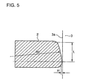
FIG.5 is a drawing for explaining gas seal performance of thepiston ring 2. In the drawing, L is gas seal length, H is an oil film retaining equivalent clearance between the circumferential surface of thepiston ring 2 and theinner surface 3a of thecylinder liner 3, and R0 is the curvature radius of the first curved surface of thepiston ring 2. The oil film retaining equivalent clearance H is inversely proportional to the curvature radius R0. The gas leak flow Q through the clearance H is presented by the following equation (1).
where, µ : friction coefficient between the outer circumferential surface of thepiston ring 2 andinner surface 3a of theliner 3, ΔP: pressure difference between upper surface and lower surface of thepiston ring 2. The smaller the value of Q is, the higher the gas seal performance of the piston ring. - According to the equation (1), the gas leak Q is inversely proportional to the curvature radius R0 of the first curved surface of the
piston ring 2. Therefore, by increasing R0, the value of Q of the above equation can be decreased, that is, gas seal performance of the piston ring can be increased. With a relative smaller value of R0 as R0=0.9D∼1D as is in the prior art, the gas seal performance between the outer circumferential surface of thepiston ring 2a andinner surface 3a of thecylinder liner 3 is relatively small, so blow-by gas increases due to insufficient gas seal performance, piston ring pack and ring groves are smeared, and sulfate corrosion on the sliding surfaces of the piston rings and cylinder liner increases due to sulfurous acid gas contained in the blow-by gas. - Further, as contact pressure (Hertzian stress) between the outer circumferential surface of the piston ring and the inner surface of the cylinder liner is inversely proportional to the square root of R0, the contact pressure increases with decreased radius R0. Therefore, it is preferable to increase the curvature radius R0 of the first curved surface of the piston ring also in a viewpoint of contact pressure of the piston ring to the cylinder liner.
- The present invention was made in light of problems of the prior art mentioned above, and the object of the invention is to provide a piston ring improved in gas sealing performance by increasing to the utmost extent the curvature radius R of the first curved surface of the outer circumferential surface of the piston ring, thereby preventing increase of blow-by gas flow due to insufficient gas sealing performance between the outer circumferential surface and the inner surface of the cylinder liner, preventing smearing of the region around piston rings due to increased leakage of combustion gas, suppressing occurrence of sulfate corrosion of the inner surface of the cylinder liner due to sulfurous acid contained in the blow-by gas, and reducing contact pressure between the sliding surface of the piston ring and the inner surface of the cylinder liner, and to provide a reciprocating internal combustion engine such as a diesel engine equipped with the piston ring at least as the top ring.
- To attain the object, the present invention proposes a piston ring of a reciprocating engine, the outer circumferential surface of the piston ring having a curved surface of a circular arc of a curvature radius R in its axial section, wherein the curvature radius R is 1.18∼1.35 times the inner diameter D of a cylinder liner in which the piston ring slides.
- By determining the curvature radius R to be 1.18D, gas leak flow Q calculated by equation (1) decreases to a half of that when the curvature radius R is 0.95D which is conventionally adopted. The maximum value of R=1.35D is determined to be 1.35D in order to evade occurrence of contact of the upper corner radiuses R1 or lower corner radius R2 do not contact directly the
inner surface 3a of thecylinder liner 3 when thepiston ring 2 tilts most heavily near the top dead center or bottom dead center of the piston stroke. When the curvature radius R is too large, the corner radius R1 or R2 contacts the inner surface of the cylinder liner with too small tilting angle of the piston ring. - Validity of determining the curvature radius R to be 1.18∼1.35 was proved by experiment on engines of cylinder bore D of 330 mm and larger.
By increasing the curvature radius R of the first curved surface of the piston ring profile to 1.18D∼1.35D as compared with 0.95D of conventional piston ring, combustion gas leak flow Q through the oil film retaining equivalent clearance H between the piston ring outer surface and the inner surface of the cylinder decreases inversely proportionally to the third power of R as is recognized from equation (1), and the gas leak flow Q decreases to about 1/3 with the piston ring of R=1.35 as compared with that of a conventional piston ring of R0=0.95D. - By the improvement in gas sealing performance in the sliding surface, blow-by gas flow is decreased, decrease in engine performance is prevented, smearing of the region around piston rings is prevented, and occurrence of sulfate corrosion of the inner surface of the cylinder liner due to sulfurous acid contained in the blow-by gas can be suppressed.
- As mentioned above, larger curvature radius R of the first curved surface of the piston ring is desirable from a viewpoint of gas sealing performance as combustion gas flow resistance through the sliding surface of the piston ring on the inner surface of the cylinder is proportional to the third power of R. By determining the curvature radius R to be 1.18∼1.35 times the cylinder bore D, said gas flow resistance is increased to 2-3 times that of a conventional piston ring of curvature radius R0 of 0,95D.
- Lower limit of R is determined to be 1.18D in order to obtain increase in the combustion gas flow resistance at least by 2 times.
- Tilting of the piston ring increases due to tilting of the piston, thermal deformation of the piston, etc. and the tilting is heaviest in the top ring located nearest to the combustion chamber. When the curvature radius R is determined to be too large, there occurs a possibility that the edge of the piston ring outer circumferential surface, i.e. the corner radius R1 or R2 contacts the inner surface of the cylinder liner and injures the inner surface of the cylinder liner. The upper limit of the curvature radius R is determined to be 1.35D in order to evade said contact of the corner radius R1 or R2 to the inner surface of the cylinder liner.
- It is preferable that a flame spray coating of molybdenum or the like which is superior in initial break-in property, anti-wear property, and anti-scuff property, is applied on the outer circumferential surface of the piston ring.
- Decrease in surface roughness of the inner surface of the cylinder liner is promoted by the abrasive action of hard molybdenum particles in the running-in period and oil retaining property of machined cast iron surface of the cylinder liner is increased.
- Further, it is preferable that among a plurality of piston rings equipped to a piston of the engine a piston ring to be located nearest to a combustion chamber of the engine is such that the center of the curvature radius R of the circular arc of the outer circumferential surface thereof is at a point apart from the center line of the height of the piston ring in the direction contrary to the combustion chamber, and each of other piston rings is such that the center of the curvature radius R of the circular arc of the outer circumferential surface thereof is on the center line of the height of the piston ring or such that the center of the curvature radius R of the circular arc of the outer circumferential surface thereof is at a point apart from the center line of the height of the piston ring in the direction contrary to the combustion chamber.
- By forming the outer circumferential surface of the top ring located nearest to the combustion chamber and exposed to severest thermal environment into the profile mentioned above, its gas sealing performance which is of principal importance for combustion gas sealing in the engine can be secured.
-
-
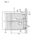
FIG.1 is an enlarged cross section of an embodiment of a piston ring of a large diesel engine according to the invention. -
FIG.2A is a schematic cross sectional view of construction surrounding a combustion chamber of a large diesel engine. -
FIG.2B is a partial cross section of piston rings inserted into ring grooves of a piston together with the piston and inner surface of the cylinder liner. -
FIG.3 are bar graphs showing decrease of piston ring contact pressure and increase of blow-by gas flow resistance through the sliding surface by increasing the curvature radius of the first curved surface of the piston ring. -
FIG.4 is an enlarged cross section of a conventional piston ring of a large diesel engine. -
FIG.5 is a drawing for explaining gas seal performance of a piston ring. - A preferred embodiment of the present invention will now be detailed with reference to the accompanying drawings. It is intended, however, that unless particularly specified, dimensions, materials, relative positions and so forth of the constituent parts in the embodiments shall be interpreted as illustrative only not as limitative of the scope of the present invention.
-
FIG. 2A is a schematic cross sectional view of construction surrounding a combustion chamber of a large diesel engine, and -
FIG. 2B is a partial cross section of piston rings inserted into ring grooves of a piston together with the piston and inner surface of the cylinder liner. - Referring to
FIG.2A , apiston 1 connected to a piston rod 8 reciprocates in acylinder liner 3. Thecylinder liner 3 is covered by acylinder head 4 to form a combustion -chamber 6 above thepiston 1. Thepiston 1 is equipped withpiston rings 2 as gas seal elements. Anexhaust valve 5 is provided in the cylinder head to face thecombustion chamber 6.FIG.2 shows a case of a crosshead type diesel engine, and the piston rod 8 is connected to a crosshead which is connected via a crosshead pin to a connecting rod which is connected to a crankshaft. The crosshead, crosshead pin, connecting rod, and crankshaft are not shown in the drawing. The crosshead is reciprocated by rotation of the crankshaft, and thepiston 1 reciprocates as the crankshaft rotates. In the case of a trunk-piston engine, the connecting rod is directly connected to thepiston 1 via a piston pin. - Referring to
FIG.2B ,piston rings 2 are inserted intoring grooves 1a of apiston 1. The outercircumferential surface 2a of thepiston rings 2 slides along the slidingsurface 3a of thecylinder liner 3 when thepiston 1 reciprocates in thecylinder liner 3. The gas pressure in thecombustion chamber 6 exerts on the upper piston ring (top ring) of thepiston rings 2 through a clearance 7 between theinner surface 3a of thecylinder liner 3 and the outer circumferential surface of the upper part of the piston 1(piston top land) extending from upper piston ring groove of thepiston ring grooves 1a. - The present invention relates to an improvement in shape of the
piston ring 2 of a large diesel engine. - Referring to
FIG.1 showing thepiston ring 2 of the invention in an enlarged cross section, thepiston ring 2 inserted in aring groove 1a reciprocates in acylinder liner 3 with its outercircumferential surface 2a contacting theinner surface 3a of thecylinder liner 3. Symbol S represents contact width and 2b a contact point. - Combustion gas intruded into the
ring groove 1a through the piston top land clearance 7(seeFIG.2B ) as shown by an arrow A is sealed by the contact of thelower surface 2t of thepiston ring 2 to the lower surface of thering groove 1a except a part of the gas leaking out through the closed gap of thepiston ring 2. - The outer circumferential surface of the
piston ring 2 is formed of a first curved surface of curvature radius R (hereafter referred to as first curved surface R), an upper corner radius R1 connecting smoothly the first curved surface R to theupper surface 2s, and a lower corner radius R2 connecting smoothly the first curved surface R to thelower surface 2t. InFIG.1 , H is the height of thepiston ring 2, B is the width of thepiston ring - The curvature radius R of the circular arc of the first curved surface of the outer
circumferential surface 2a is determined to be R=1.18D-1.35D, where D is the inner diameter of thecylinder 3. - For example, in a case of a large diesel engine of cylinder bore of D=850 mm, the outer circumferential surface profile of the
piston ring 2 is determined to be: R=1150 mm, and R1=R2=1.25 mm. - The range of curvature radius R that R=1.18D∼1.35D is determined on the basis of the following consideration:
- The minimum value of R=1.18D is determined so that the gas leak flow Q calculated by equation (1) decreases to about half of that when R=0.95D which is a value adopted conventionally.
- The maximum value of R=1.35D is determined so that the upper corner radiuses R1 or lower corner radius R2 do not contact directly the
inner surface 3a of thecylinder liner 3 when thepiston ring 2 tilts most heavily near the top dead center or bottom dead center of the piston stroke. When the curvature radius R is too large, the corner radius R1 or R2 contacts the inner surface of the cylinder liner with too small tilting angle of the piston ring. - Therefore, with a piston ring with the curvature radius R larger than the maximum value of 1.35D, it may happen that the upper corner radius R1 or lower corner radius R2 contacts directly to the
inner surface 3a of thecylinder liner 3. - As mentioned above, larger curvature radius R of the first curved surface of the
piston ring 2 is desirable from a viewpoint of gas sealing performance as combustion gas flow resistance through the sliding surface of the piston ring on the inner surface of the cylinder is proportional to the third power of R. By determining the curvature radius R to be 1.18∼1.35 times the cylinder bore D, said gas flow resistance is increased to 2-3 times that of a conventional piston ring of curvature radius R0 of 0, 95D. - Lower limit of R is determined to be 1.18D in order to obtain increase in the combustion gas flow resistance at least by 2 times.
- Tilting of the piston ring increases due to tilting of the piston, thermal deformation of the piston, etc. and the tilting is heaviest in the top ring located nearest to the combustion chamber. When the curvature radius R is determined to be too large, there occurs a possibility that the edge of the piston ring outer circumferential surface, i.e. the corner radius R1 or R2 contacts the inner surface of the cylinder liner and injures the inner surface of the cylinder liner. The upper limit of the curvature radius R is determined to be 1.35D in order to evade said contact of the corner radius R1 or R2 to the inner surface of the cylinder liner.
- Validity of determining the curvature radius R to be 1.18∼1.35 was proved by experiment on engines of cylinder bore D of 330 mm or larger.
- In
FIG.3 , piston ring profile of which the curvature radius R is 1. 35D is shown in (A1), and that of conventional piston ring of which the curvature radius R0 is 0.95D is shown in (A0).
Lubrication oil around the sliding surface is indicate by a letter U. - Contact pressure between the outer circumferential surface of the
piston ring 2 and the inner surface of thecylinder liner 3 is compared in the bar graph(1) inFIG. 3 . Contact pressure(Hertzian stress) x1 of the piston ring of R=1.35D shown in (A1) is smaller by X1=17% as compared with that of the piston ring of R0=0.95D shown in (A0). - Blow-by gas flow resistance is compared in the bar graph (2) in
FIG.3 . Blow-by gas flow resistance x2 of the piston ring of R=1.35D shown in (A1) is about 3 times larger than that of the piston ring of R0=0.95D shown in (A0). In the bar graph (2) is also shown blow-by gas flow resistance x3 of a piston ring of R=1.18D. The gas flow resistance x3 is about 2 times that of the piston ring of R0=0.95D. - By increasing the curvature radius R of the first curved surface of the piston ring profile to 1.18D∼1.35D as compared with 0.95D of conventional piston ring, combustion gas leak flow Q through the oil film retaining equivalent clearance H between the piston ring outer surface and the inner surface of the cylinder decreases inversely proportionally to the third power of R as is recognized from equation (1), and the gas leak flow Q decreases to about 1/3 with the piston ring of R=1.35 as compared with that of a conventional piston ring of R0=0.95D.
- By the improvement in gas sealing performance in the sliding surface, blow-by gas flow is decreased, decrease in engine performance is prevented, smearing of the region around piston rings is prevented, and occurrence of sulfate corrosion of the
inner surface 3a of thecylinder liner 3 due to sulfurous acid contained in the blow-by gas can be suppressed. - Further, it is preferable that a flame spray coating of molybdenum or the like which is superior in initial break-in property, anti-wear property, and anti-scuff property, is applied on the sliding
surface 2a of thepiston ring 2. Decrease in surface roughness of theinner surface 3a of thecylinder liner 3 is promoted by the abrasive action of hard molybdenum particles in the running-in period and oil retaining property of machinedcast iron surface 3a of thecylinder liner 3 is increased. - It is preferable that the first curved surface of the top ring located nearest to the combustion chamber is formed to be a circular arc of curvature radius R of 1.18D∼1.35D with the center of curvature radius R being positioned at a point below the
center line 2c of the piston ring height toward thelower surface 2t of the piston ring, and that the first curved surface of other piston ring or rings is formed to be a circular arc of curvature radius R of 1.18D∼1.35D with the center of curvature radius R being positioned at a point on thecenter line 2c of the piston ring height or with the center of curvature radius R being positioned at a point below thecenter line 2c of the piston ring height toward thelower surface 2t of the piston ring. - By forming the outer circumferential surface of the top ring located nearest to the combustion chamber and exposed to severest thermal environment into the profile mentioned above, its gas sealing performance can be secured.
- The second and other piston rings may be formed to have a first curved surface of which the center of the curvature radius is on the
center line 2c. - According to the invention, a piston ring improved in gas sealing performance by increasing to the utmost extent the curvature radius R of the first curved surface of the outer circumferential surface of the piston ring, is provided. With the piston ring, blow-by gas flow through the sliding surface between the outer circumferential surface of the piston ring and the inner surface of the cylinder liner is decreased, smearing of the region around piston rings due to leakage of combustion gas is prevented, occurrence of sulfate corrosion of the inner surface of the cylinder liner due to sulfurous acid contained in the blow-by gas can be suppressed, and contact pressure between the sliding surface of the piston ring and the inner surface of the cylinder liner is reduced. By adopting the piston ring according to the invention at least as the top ring, a reciprocating internal combustion engine, particularly a diesel engine improved in output performance and durability will be provided.
Claims (5)
- A piston ring of a reciprocating engine, the outer circumferential surface of the piston ring having a curved surface of a circular arc of a curvature radius R in its axial section, wherein the curvature radius R is 1.18∼1.35 times the inner diameter D of a cylinder liner in which the piston ring slides.
- The piston ring according to claim 1, wherein a flame spray coating of molybdenum or the like which is superior in initial break-in property, anti-wear property, and anti-scuff property, is applied on the outer circumferential surface of the piston ring.
- Piston ring according to claim 1 or 2, wherein among a plurality of piston rings equipped to a piston of the engine a piston ring to be located nearest to a combustion chamber of the engine is such that the center of the curvature radius R of the circular arc of the outer circumferential surface thereof is at a point apart from the center line of the height of the piston ring in the direction contrary to the combustion chamber, and each of other piston rings is such that the center of the curvature radius R of the circular arc of the outer circumferential surface thereof is on the center line of the height of the piston ring or such that the center of the curvature radius R of the circular arc of the outer circumferential surface thereof is at a point apart from the center line of the height of the piston ring in the direction contrary to the combustion chamber.
- The piston ring according to any one of the preceding claims, wherein the reciprocating engine is a diesel engine.
- A diesel engine having a piston which is equipped with the piston ring of any one of the preceding claims at least has a top piston ring located nearest to a combustion chamber of the engine.
Applications Claiming Priority (1)
| Application Number | Priority Date | Filing Date | Title |
|---|---|---|---|
| JP2007261572A JP2009091927A (en) | 2007-10-05 | 2007-10-05 | Piston ring for reciprocating engine |
Publications (2)
| Publication Number | Publication Date |
|---|---|
| EP2045488A1 true EP2045488A1 (en) | 2009-04-08 |
| EP2045488B1 EP2045488B1 (en) | 2010-09-29 |
Family
ID=40239898
Family Applications (1)
| Application Number | Title | Priority Date | Filing Date |
|---|---|---|---|
| EP08007925A Not-in-force EP2045488B1 (en) | 2007-10-05 | 2008-04-24 | Piston ring of reciprocating engine |
Country Status (6)
| Country | Link |
|---|---|
| EP (1) | EP2045488B1 (en) |
| JP (1) | JP2009091927A (en) |
| KR (1) | KR20090035413A (en) |
| CN (1) | CN101403348B (en) |
| DE (1) | DE602008002794D1 (en) |
| DK (1) | DK2045488T3 (en) |
Cited By (6)
| Publication number | Priority date | Publication date | Assignee | Title |
|---|---|---|---|---|
| MD20100007A2 (en) * | 2010-01-18 | 2011-06-30 | Ион РАССОХИН | Process for changing the standard sizes of parts of the internal combustion engine |
| DE102013200261A1 (en) * | 2013-01-10 | 2014-07-10 | Federal-Mogul Burscheid Gmbh | Piston ring for internal combustion engines with increased fatigue strength and method for its production |
| WO2019192828A1 (en) * | 2018-04-03 | 2019-10-10 | Federal-Mogul Burscheid Gmbh | Piston ring and piston ring/piston combination with improved wear properties |
| US11320049B2 (en) | 2018-11-15 | 2022-05-03 | Tpr Co., Ltd. | Piston ring combination |
| US11603929B2 (en) | 2020-04-30 | 2023-03-14 | Tpr Co., Ltd. | Wire for piston ring, and manufacturing method of piston ring |
| CN116696586A (en) * | 2022-03-02 | 2023-09-05 | 曼能解决方案(曼能解决方案德国股份公司)分公司 | Piston ring for large two-stroke turbocharged uniflow scavenged cross-head internal combustion engine |
Families Citing this family (16)
| Publication number | Priority date | Publication date | Assignee | Title |
|---|---|---|---|---|
| DE102012000241B4 (en) * | 2011-05-10 | 2016-12-08 | Federal-Mogul Burscheid Gmbh | Piston ring for 2-stroke engines |
| DE102012013803A1 (en) | 2012-04-19 | 2013-10-24 | Federal-Mogul Burscheid Gmbh | Piston ring for combustion engine, has transition area forming sharp striking edge in contact area from lower flank area, while curved shell surface extending in direction of upper flank area is protruded from striking edge |
| WO2014196614A1 (en) * | 2013-06-07 | 2014-12-11 | 株式会社リケン | Piston ring, raw material therefor, and production method for both |
| JP6446187B2 (en) * | 2014-06-27 | 2018-12-26 | 株式会社リケン | piston ring |
| JP6446188B2 (en) * | 2014-06-27 | 2018-12-26 | 株式会社リケン | piston ring |
| WO2015199183A1 (en) * | 2014-06-27 | 2015-12-30 | 株式会社リケン | Piston ring |
| WO2016038916A1 (en) * | 2014-09-12 | 2016-03-17 | Tpr株式会社 | Combined oil ring |
| JP6533670B2 (en) * | 2015-03-12 | 2019-06-19 | 株式会社リケン | side rail |
| DE102015009587B4 (en) * | 2015-07-24 | 2018-11-22 | Federal-Mogul Burscheid Gmbh | Compression piston ring |
| JP6195949B2 (en) * | 2016-02-26 | 2017-09-13 | 株式会社リケン | piston ring |
| JP6762657B2 (en) * | 2016-04-06 | 2020-09-30 | 株式会社リケン | side rail |
| WO2019008780A1 (en) | 2017-07-05 | 2019-01-10 | Tpr株式会社 | Combined oil ring |
| CN110762202A (en) * | 2019-12-24 | 2020-02-07 | 潍柴动力股份有限公司 | Piston ring, piston assembly and engine |
| CN111075598B (en) * | 2019-12-28 | 2021-03-16 | 潍柴动力股份有限公司 | A piston ring, piston assembly and engine |
| CN114178436A (en) * | 2021-11-10 | 2022-03-15 | 安庆帝伯格茨活塞环有限公司 | Method for processing diesel engine ring and forming equipment thereof |
| JP2023151267A (en) * | 2022-03-31 | 2023-10-16 | 株式会社ジャパンエンジンコーポレーション | Pistons and marine internal combustion engines |
Citations (6)
| Publication number | Priority date | Publication date | Assignee | Title |
|---|---|---|---|---|
| US4359230A (en) | 1978-02-16 | 1982-11-16 | Associated Engineering Italy S.P.A. | Piston ring with wear resistant coating |
| GB2117086A (en) * | 1982-03-12 | 1983-10-05 | Dana Corp | Piston rings |
| DE3940301A1 (en) * | 1989-12-06 | 1991-06-13 | Friedhelm Stecher | Piston ring with gas seal - has depressurised underside, with active contact surface and cylindrical surface |
| JPH08296740A (en) | 1995-04-26 | 1996-11-12 | Ishikawajima Harima Heavy Ind Co Ltd | piston ring |
| US5779243A (en) | 1996-11-21 | 1998-07-14 | Delaware Capital Formation, Inc. | Piston ring set for reciprocating engines |
| JP2002039384A (en) * | 2000-07-28 | 2002-02-06 | Nippon Piston Ring Co Ltd | piston ring |
Family Cites Families (3)
| Publication number | Priority date | Publication date | Assignee | Title |
|---|---|---|---|---|
| JPS5143306Y1 (en) * | 1966-10-08 | 1976-10-21 | ||
| JPS57196238U (en) * | 1981-06-08 | 1982-12-13 | ||
| JPS6232266A (en) * | 1985-08-02 | 1987-02-12 | Riken Corp | Manufacture of piston ring for internal-combustion engine |
-
2007
- 2007-10-05 JP JP2007261572A patent/JP2009091927A/en active Pending
-
2008
- 2008-04-24 DK DK08007925.4T patent/DK2045488T3/en active
- 2008-04-24 DE DE602008002794T patent/DE602008002794D1/en active Active
- 2008-04-24 EP EP08007925A patent/EP2045488B1/en not_active Not-in-force
- 2008-04-29 KR KR1020080040044A patent/KR20090035413A/en not_active Ceased
- 2008-04-30 CN CN2008100949302A patent/CN101403348B/en active Active
Patent Citations (6)
| Publication number | Priority date | Publication date | Assignee | Title |
|---|---|---|---|---|
| US4359230A (en) | 1978-02-16 | 1982-11-16 | Associated Engineering Italy S.P.A. | Piston ring with wear resistant coating |
| GB2117086A (en) * | 1982-03-12 | 1983-10-05 | Dana Corp | Piston rings |
| DE3940301A1 (en) * | 1989-12-06 | 1991-06-13 | Friedhelm Stecher | Piston ring with gas seal - has depressurised underside, with active contact surface and cylindrical surface |
| JPH08296740A (en) | 1995-04-26 | 1996-11-12 | Ishikawajima Harima Heavy Ind Co Ltd | piston ring |
| US5779243A (en) | 1996-11-21 | 1998-07-14 | Delaware Capital Formation, Inc. | Piston ring set for reciprocating engines |
| JP2002039384A (en) * | 2000-07-28 | 2002-02-06 | Nippon Piston Ring Co Ltd | piston ring |
Cited By (8)
| Publication number | Priority date | Publication date | Assignee | Title |
|---|---|---|---|---|
| MD20100007A2 (en) * | 2010-01-18 | 2011-06-30 | Ион РАССОХИН | Process for changing the standard sizes of parts of the internal combustion engine |
| DE102013200261A1 (en) * | 2013-01-10 | 2014-07-10 | Federal-Mogul Burscheid Gmbh | Piston ring for internal combustion engines with increased fatigue strength and method for its production |
| WO2019192828A1 (en) * | 2018-04-03 | 2019-10-10 | Federal-Mogul Burscheid Gmbh | Piston ring and piston ring/piston combination with improved wear properties |
| US11578799B2 (en) | 2018-04-03 | 2023-02-14 | Federal-Mogul Burscheid Gmbh | Piston ring and piston ring/piston combination with improved wear properties |
| US11320049B2 (en) | 2018-11-15 | 2022-05-03 | Tpr Co., Ltd. | Piston ring combination |
| US11603929B2 (en) | 2020-04-30 | 2023-03-14 | Tpr Co., Ltd. | Wire for piston ring, and manufacturing method of piston ring |
| CN116696586A (en) * | 2022-03-02 | 2023-09-05 | 曼能解决方案(曼能解决方案德国股份公司)分公司 | Piston ring for large two-stroke turbocharged uniflow scavenged cross-head internal combustion engine |
| CN116696586B (en) * | 2022-03-02 | 2024-06-07 | 曼能解决方案(曼能解决方案德国股份公司)分公司 | Piston ring for large two-stroke turbocharged uniflow scavenged cross-head internal combustion engine |
Also Published As
| Publication number | Publication date |
|---|---|
| CN101403348A (en) | 2009-04-08 |
| DK2045488T3 (en) | 2010-12-13 |
| JP2009091927A (en) | 2009-04-30 |
| KR20090035413A (en) | 2009-04-09 |
| CN101403348B (en) | 2011-05-25 |
| DE602008002794D1 (en) | 2010-11-11 |
| EP2045488B1 (en) | 2010-09-29 |
Similar Documents
| Publication | Publication Date | Title |
|---|---|---|
| EP2045488B1 (en) | Piston ring of reciprocating engine | |
| US6357341B1 (en) | Piston of internal combustion engine | |
| EP1630396B1 (en) | A sliding structure for a reciprocating internal combustion engine and a reciprocating internal combustion engine using the sliding structure | |
| US20090013866A1 (en) | Three-piece oil ring and combination of the three-piece oil ring and piston | |
| US10119613B2 (en) | Wrist pin and method of reducing wear between members thereof, connecting rod, piston and methods of constructing same | |
| EP3043054B1 (en) | Cuff-ring for a cylinder liner | |
| US9657839B2 (en) | Reduced friction piston rings | |
| US20070272078A1 (en) | Piston Device for Internal Combustion Engine | |
| CN110506173B (en) | Pistons and piston rings for internal combustion engines | |
| US6196179B1 (en) | Internal combustion engine | |
| EP3412940A1 (en) | Piston ring for an internal combustion engine | |
| JP6337058B2 (en) | Top piston ring for crosshead turbocharged large two-stroke compression ignition internal combustion engine | |
| US9856981B2 (en) | Reduced friction piston ring | |
| EP0411913A1 (en) | Piston assembly of internal combustion engine | |
| JP2005264978A (en) | Pressure ring | |
| EP2113690A1 (en) | Combined oil ring | |
| US12292118B2 (en) | Piston ring | |
| JP2010222985A (en) | Piston ring and internal combustion engine | |
| JP2009185865A (en) | Piston ring, and piston and engine using the same | |
| US6189893B1 (en) | Piston ring | |
| WO2009033115A2 (en) | High efficiency piston ring | |
| RU2119108C1 (en) | Piston sealing member | |
| JP7665852B1 (en) | Piston ring for hydrogen fueled internal combustion engine and method for inhibiting corrosion of piston ring in hydrogen fueled internal combustion engine | |
| US7188841B1 (en) | Secondary piston seal | |
| CN105143732A (en) | Steel piston with fourth land guidance and improved friction characteristics |
Legal Events
| Date | Code | Title | Description |
|---|---|---|---|
| PUAI | Public reference made under article 153(3) epc to a published international application that has entered the european phase |
Free format text: ORIGINAL CODE: 0009012 |
|
| 17P | Request for examination filed |
Effective date: 20080424 |
|
| AK | Designated contracting states |
Kind code of ref document: A1 Designated state(s): AT BE BG CH CY CZ DE DK EE ES FI FR GB GR HR HU IE IS IT LI LT LU LV MC MT NL NO PL PT RO SE SI SK TR |
|
| AX | Request for extension of the european patent |
Extension state: AL BA MK RS |
|
| AKX | Designation fees paid |
Designated state(s): CH DE DK LI |
|
| GRAP | Despatch of communication of intention to grant a patent |
Free format text: ORIGINAL CODE: EPIDOSNIGR1 |
|
| GRAS | Grant fee paid |
Free format text: ORIGINAL CODE: EPIDOSNIGR3 |
|
| GRAA | (expected) grant |
Free format text: ORIGINAL CODE: 0009210 |
|
| AK | Designated contracting states |
Kind code of ref document: B1 Designated state(s): CH DE DK LI |
|
| REG | Reference to a national code |
Ref country code: CH Ref legal event code: EP Ref country code: CH Ref legal event code: NV Representative=s name: E. BLUM & CO. AG PATENT- UND MARKENANWAELTE VSP |
|
| REF | Corresponds to: |
Ref document number: 602008002794 Country of ref document: DE Date of ref document: 20101111 Kind code of ref document: P |
|
| REG | Reference to a national code |
Ref country code: DK Ref legal event code: T3 |
|
| PLBE | No opposition filed within time limit |
Free format text: ORIGINAL CODE: 0009261 |
|
| STAA | Information on the status of an ep patent application or granted ep patent |
Free format text: STATUS: NO OPPOSITION FILED WITHIN TIME LIMIT |
|
| REG | Reference to a national code |
Ref country code: DE Ref legal event code: R097 Ref document number: 602008002794 Country of ref document: DE Effective date: 20110630 |
|
| PGFP | Annual fee paid to national office [announced via postgrant information from national office to epo] |
Ref country code: DE Payment date: 20120502 Year of fee payment: 5 Ref country code: DK Payment date: 20120411 Year of fee payment: 5 Ref country code: CH Payment date: 20120412 Year of fee payment: 5 |
|
| REG | Reference to a national code |
Ref country code: CH Ref legal event code: PL |
|
| REG | Reference to a national code |
Ref country code: DK Ref legal event code: EBP Effective date: 20130430 |
|
| PG25 | Lapsed in a contracting state [announced via postgrant information from national office to epo] |
Ref country code: DE Free format text: LAPSE BECAUSE OF NON-PAYMENT OF DUE FEES Effective date: 20131101 Ref country code: LI Free format text: LAPSE BECAUSE OF NON-PAYMENT OF DUE FEES Effective date: 20130430 Ref country code: CH Free format text: LAPSE BECAUSE OF NON-PAYMENT OF DUE FEES Effective date: 20130430 |
|
| REG | Reference to a national code |
Ref country code: DE Ref legal event code: R119 Ref document number: 602008002794 Country of ref document: DE Effective date: 20131101 |
|
| PG25 | Lapsed in a contracting state [announced via postgrant information from national office to epo] |
Ref country code: DK Free format text: LAPSE BECAUSE OF NON-PAYMENT OF DUE FEES Effective date: 20130430 |