EP2045475A2 - Stapelbare Halterungsanordnung mit Anzeige-/Schließfunktionen - Google Patents
Stapelbare Halterungsanordnung mit Anzeige-/Schließfunktionen Download PDFInfo
- Publication number
- EP2045475A2 EP2045475A2 EP08253244A EP08253244A EP2045475A2 EP 2045475 A2 EP2045475 A2 EP 2045475A2 EP 08253244 A EP08253244 A EP 08253244A EP 08253244 A EP08253244 A EP 08253244A EP 2045475 A2 EP2045475 A2 EP 2045475A2
- Authority
- EP
- European Patent Office
- Prior art keywords
- rung
- sleeve
- hub assembly
- fastener
- component
- Prior art date
- Legal status (The legal status is an assumption and is not a legal conclusion. Google has not performed a legal analysis and makes no representation as to the accuracy of the status listed.)
- Withdrawn
Links
Images










Classifications
-
- F—MECHANICAL ENGINEERING; LIGHTING; HEATING; WEAPONS; BLASTING
- F16—ENGINEERING ELEMENTS AND UNITS; GENERAL MEASURES FOR PRODUCING AND MAINTAINING EFFECTIVE FUNCTIONING OF MACHINES OR INSTALLATIONS; THERMAL INSULATION IN GENERAL
- F16B—DEVICES FOR FASTENING OR SECURING CONSTRUCTIONAL ELEMENTS OR MACHINE PARTS TOGETHER, e.g. NAILS, BOLTS, CIRCLIPS, CLAMPS, CLIPS OR WEDGES; JOINTS OR JOINTING
- F16B35/00—Screw-bolts; Stay-bolts; Screw-threaded studs; Screws; Set screws
- F16B35/04—Screw-bolts; Stay-bolts; Screw-threaded studs; Screws; Set screws with specially-shaped head or shaft in order to fix the bolt on or in an object
-
- F—MECHANICAL ENGINEERING; LIGHTING; HEATING; WEAPONS; BLASTING
- F16—ENGINEERING ELEMENTS AND UNITS; GENERAL MEASURES FOR PRODUCING AND MAINTAINING EFFECTIVE FUNCTIONING OF MACHINES OR INSTALLATIONS; THERMAL INSULATION IN GENERAL
- F16B—DEVICES FOR FASTENING OR SECURING CONSTRUCTIONAL ELEMENTS OR MACHINE PARTS TOGETHER, e.g. NAILS, BOLTS, CIRCLIPS, CLAMPS, CLIPS OR WEDGES; JOINTS OR JOINTING
- F16B19/00—Bolts without screw-thread; Pins, including deformable elements; Rivets
- F16B19/02—Bolts or sleeves for positioning of machine parts, e.g. notched taper pins, fitting pins, sleeves, eccentric positioning rings
-
- F—MECHANICAL ENGINEERING; LIGHTING; HEATING; WEAPONS; BLASTING
- F16—ENGINEERING ELEMENTS AND UNITS; GENERAL MEASURES FOR PRODUCING AND MAINTAINING EFFECTIVE FUNCTIONING OF MACHINES OR INSTALLATIONS; THERMAL INSULATION IN GENERAL
- F16B—DEVICES FOR FASTENING OR SECURING CONSTRUCTIONAL ELEMENTS OR MACHINE PARTS TOGETHER, e.g. NAILS, BOLTS, CIRCLIPS, CLAMPS, CLIPS OR WEDGES; JOINTS OR JOINTING
- F16B5/00—Joining sheets or plates, e.g. panels, to one another or to strips or bars parallel to them
- F16B5/06—Joining sheets or plates, e.g. panels, to one another or to strips or bars parallel to them by means of clamps or clips
- F16B5/0685—Joining sheets or plates to strips or bars
-
- H—ELECTRICITY
- H02—GENERATION; CONVERSION OR DISTRIBUTION OF ELECTRIC POWER
- H02G—INSTALLATION OF ELECTRIC CABLES OR LINES, OR OF COMBINED OPTICAL AND ELECTRIC CABLES OR LINES
- H02G3/00—Installations of electric cables or lines or protective tubing therefor in or on buildings, equivalent structures or vehicles
- H02G3/30—Installations of cables or lines on walls, floors or ceilings
- H02G3/32—Installations of cables or lines on walls, floors or ceilings using mounting clamps
-
- Y—GENERAL TAGGING OF NEW TECHNOLOGICAL DEVELOPMENTS; GENERAL TAGGING OF CROSS-SECTIONAL TECHNOLOGIES SPANNING OVER SEVERAL SECTIONS OF THE IPC; TECHNICAL SUBJECTS COVERED BY FORMER USPC CROSS-REFERENCE ART COLLECTIONS [XRACs] AND DIGESTS
- Y10—TECHNICAL SUBJECTS COVERED BY FORMER USPC
- Y10T—TECHNICAL SUBJECTS COVERED BY FORMER US CLASSIFICATION
- Y10T403/00—Joints and connections
- Y10T403/32—Articulated members
- Y10T403/32975—Rotatable
- Y10T403/32983—Rod in socket
Definitions
- the present invention relates to a stackable mount assembly. More particularly, the present invention relates to a stackable mount assembly including indexing and/or locking features.
- Ringposts have been utilized for wire bundle management in aircraft.
- Nylon Molding Corporation's RP series ringposts described in U.S. Patent Nos. 6,880,787 and 6,880,788 , and U.S. Design Patent Nos. D496,851 and D497,100 , may provide one to six levels of wiring on one rack or support structure, and may accommodate bundles up to 11 ⁇ 4 inch in diameter.
- the RP1700 ringpost includes a single ringpost without a screw.
- the RP1703 and RP1704 ringposts include a standard size hex head screw insert molded into a single and double ringpost, respectively, along with a steel socket which is also insert molded.
- Patent Application Publication No. 2004/0206855 A1 assigned to Panduit Corporation, describes a ringpost that allows a hub to freely rotate about a fastener after the ringpost has been torqued down into a mounting structure.
- a stackable mount assembly including indexing and/or locking features.
- Certain embodiments of the present invention provide a hub assembly for a stackable mount.
- the hub assembly includes a sleeve and at least one rung component.
- the rung component is rotatably connected to the sleeve.
- the sleeve includes a first set of indexing teeth and the at least one rung component includes a second set of indexing teeth.
- the first set of indexing teeth and the second set of indexing teeth engage to allow the at least one rung component to indexically rotate about the sleeve at a desired angle of rotation.
- the sleeve includes a first set of locking teeth and the at least one rung component includes a second set of locking teeth.
- the first set of locking teeth and the second set of locking teeth engage to lock the at least one rung component in a desired position and prevent further rotation of the at least one rung component about the sleeve.
- Certain embodiments of the present invention provide a stackable mount for a stackable mount assembly.
- the stackable mount includes a fastener and a hub.
- the hub is rotatably connected to the fastener.
- the fastener includes at least one rib.
- the hub includes a plurality of slots. The at least one rib and the plurality of slots engage to allow the hub to indexically rotate about the fastener at a desired angle of rotation.
- FIG. 1 is a top front perspective view of a stackable mount assembly of the present invention, shown having two cable ties for securing various size wire bundles therein.
- FIG. 2 is a side elevational view of the stackable mount assembly of FIG. 1 .
- FIG. 3 is a top front perspective view of the first mount utilized in the stackable mount assembly of FIG. 1 .
- FIG. 4 is a bottom front perspective view of the first mount utilized in the stackable mount assembly of FIG. 1 .
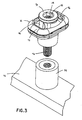
- FIG. 5 is an exploded top perspective view of the mount of FIG. 3 , shown positioned above a first mount secured to a mounting structure.
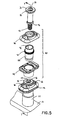
- FIG. 6 is an enlarged view of FIG. 5 , showing the hub assembly.
- FIG. 7 is a cross-sectional view taken along lines 7-7 of FIG. 5 .
- FIG. 8 is a cross-sectional view taken along lines 8-8 of FIG. 1 .
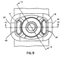
- FIG. 9 is a top view of the mount of FIG. 3 .
- FIG. 10 is a cross-sectional view taken along lines 10-10 of FIG. 9 , showing the mount in an "open" position.
- FIG. 11 is an enlarged view of FIG. 10 , showing the locking teeth.
- FIG. 12 is a cross-sectional view taken along lines 12-12 of FIG. 11 , showing the locking teeth.
- FIG. 13 is a cross-sectional view taken along lines 13-13 of FIG. 9 .
- FIG. 14 is an enlarged view of FIG. 13 , showing the indexing teeth.
- FIG. 15 is a cross-sectional view taken along lines 15-15 of FIG. 14 , showing the indexing teeth.
- FIG. 16 is a cross-sectional view taken along lines 16-16 of FIG. 10 .
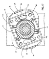
- FIG. 17 is a cross-sectional view similar to FIG. 16 , showing the rung components rotated counterclockwise about the sleeve.
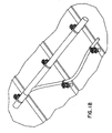
- FIG. 18 is a top front perspective view of an exemplary wiring configuration, including a breakout.
- FIG. 19 is a top view of the mount of FIG. 3 , showing the optional spring arms.
- FIG. 20 is an enlarged view of FIG. 5 , showing the optional spring arms.
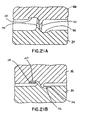
- FIGS. 21A-B are cross-section views taken along lines 21-21 of FIG. 19 , showing the optional spring arms collapsing into shallow pockets.
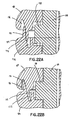
- FIGS. 22A-B are cross-section views similar to FIGS. 21A-B , showing the optional spring arms collapsing into deep pockets.
- FIG. 23 is an enlarged view of FIG. 5 , showing the optional rung teeth.
- FIGS. 24A-B are top front perspective views of the first mount utilized in the stackable mount assembly of FIG. 1 , showing the optional rung teeth in "open” and “closed” positions.
- FIGS. 25-26 illustrate a mount according to an alternative embodiment of the present invention.
- the illustrated embodiments of the present invention are directed to a stackable mount assembly that includes indexing and/or locking features.
- FIGS. 1-2 show a fully assembled stackable mount assembly 20.
- the stackable mount assembly 20 includes a mounting structure 22 having a base 24, a first mount 26, a second mount 28, a third mount 30, a first cable tie 32, a first wire bundle 34, a second cable tie 36, and a second wire bundle 38.
- the first mount 26, the second mount 28, and the third mount 30 are substantially identical. It is likewise contemplated that the stackable mount assembly 20 may include any number of stackable mounts.
- the first cable tie 32 secures the first wire bundle 34 to one rung of the second mount 28, and the second cable tie 36 secures the second wire bundle 38 to one rung of the second mount 28 and one rung of the third mount 30.
- the cable tie should pass through one rung on each of two adjacent mounts.
- the cable tie should only pass through one rung on one mount. Therefore, as shown in FIGS. 1-2 , the first wire bundle 34 is an example of a small wire bundle, and the second wire bundle 38 is an example of a large wire bundle. It is likewise contemplated that stackable mount assembly 20 may include any number of cable ties and wire bundles.
- FIGS. 3-4 show the first mount 26 prior to attachment to the mounting structure 22, and FIG. 5 shows the first mount 26 after attachment to the mounting structure 22.
- the first mount 26 includes a fastener 40 snap-fitted within a hub assembly 42.
- the fastener 40 is a threaded fastener made of titanium, and the hub assembly 42 is made of plastic.
- the titanium fastener 40 is lighter than a fastener having a steel socket and a titanium stud, and thus provides a weight advantage over existing mounts.
- each of the second mount 28 and the third mount 30 includes a fastener snap-fitted within a hub assembly.
- the fastener 40 includes a head 52 and a shoulder 66, which retain the hub assembly 42.
- the head 52 includes a hex pocket 54 for receiving an allen head tool (not shown) utilized to tighten the first mount 26 to the mounting structure 22.
- An aperture 56 runs down the primary axis of the fastener 40, and the fastener 40 has internal threads 58 to facilitate engagement with a stud 60 of a fastener 62 protruding from the second mount 28, as shown in FIG. 7 .
- the shoulder 66 of the fastener 40 extends just below the bottom of the hub assembly 42 so as to allow rotation and/or indexing of the hub assembly 42 and/or the components thereof after the fastener 40 is torqued down to the mounting structure 22.
- the shoulder 66 may be even with the bottom of the hub assembly 42, while still allowing rotation and/or indexing of the hub assembly 42 and/or the components thereof after the fastener 40 is torqued down to the mounting structure 22.
- the hub assembly 42 includes a first rung component 84, a second rung component 86, and a sleeve 88.
- the rung components 84, 86 encapsulate the sleeve 88 to form the hub assembly 42.
- the fastener 40 is snap-fitted within the hub assembly 42. More particularly, the sleeve 88 is rotatably connected to the fastener 40 via snap-fit features 92, as best seen in FIG. 11 .
- the sleeve 88 and the fastener 40 include flats 96, which prevent the sleeve 88 from rotating about the fastener 40.
- the rung components 84, 86 are adapted to rotate about the longitudinal axis of the sleeve 88.
- the first rung component 84 is rotatably connected to one end of the sleeve 88, and is supported by snap-fit features 94 on the first rung component 84 and the sleeve 88, as best seen in FIG. 11 .
- the second rung component 86 is rotatably connected to the other end of the sleeve 88, and is supported by a circumferential rib 98 on the sleeve 88, as best seen in FIG. 7 .
- the rung components 84, 86 include alignment features, such as tapered bosses 104 and pockets 108.
- the alignment features prevent the rung components 84, 86 from rotating independently about the sleeve 88.
- the tapered bosses 104 on the first rung component 84 engage the corresponding pockets 108 on the second rung component 86
- the tapered bosses 104 on the second rung component 86 engage the corresponding pockets 108 on the first rung component 84, thereby preventing the rung components 84, 86 from rotating independently about the sleeve 88.
- the rung components 84, 86 and the sleeve 88 include indexing teeth 114 and 118, respectively.
- the indexing teeth 114 on the rung components 84, 86 engage the corresponding indexing teeth 118 on the sleeve 88, thereby preventing the rung components 84, 86 from freely rotating about the sleeve 88, but allowing the rung components 84, 86 to index or rotate about the sleeve 88 at an index angle, for example, 7.5°, 15°, 30°, 45°, 90°, 180°, or 360°.
- the index angle is determined based at least in part on the number of and/or spacing between the indexing teeth 114, 118, and may vary between 0° and 360°.
- the rung components 84, 86 and the sleeve 88 include locking teeth 124 and 128, respectively.
- a wire bundle such as the first wire bundle 34 or the second wire bundle 38
- a cable tie such as the first cable tie 32 or the second cable tie 36
- the locking teeth 124 on the rung components 84, 86 may engage the corresponding locking teeth 128 on the sleeve 88, thereby preventing the rung components 84, 86 from rotating and/or indexing about the sleeve 88, and thus, locking the hub assembly 42 in a desired position and/or orientation.
- the interior surfaces 154 of the rung components 84, 86 may be curved, as best seen in FIG. 10 , to shift the point of contact between the rung components 84, 86 closest to the rungs 46 and cable ties 32, 36, which may enhance the engagement force applied to the locking teeth 124, 128.
- the rung components 84, 86 may include optional spring arms 132 to separate the rung components 84, 86.
- the optional spring arms 132 prevent the locking teeth 124 on the rung components 84, 86 from engaging the locking teeth 128 on the sleeve, thereby allowing the rung components 84, 86 to rotate and/or index about the sleeve 88, as described above.
- the spring arms 132 may collapse into shallow pockets 134, as best seen in FIGS. 21A-B , and/or tapered pockets 136, as best seen in FIGS. 22A-B .
- the rung components 84, 86 may include optional rung teeth 144.
- the rung teeth 144 are adapted to at least partially cover the gap between the rung components 84, 86 when the rung components 84, 86 are separated (e.g., when the rung components 84, 86 are not bound together by a cable tie, such as the first cable tie 32 or the second cable tie 36), thereby preventing wires or other objects from getting caught between the rung components 84, 86, which could damage the wires and/or cause a potential safety hazard. Additionally, the rung teeth 144 may act as alignment features, thereby preventing the rung components 84, 86 from independently rotating and/or indexing about the sleeve 88.
- the hub assembly 42 includes two rungs 46, each adapted to receive one or more cable ties, such as cable ties 32, 36, for securing one or more wire bundles, such as wire bundles 34, 38. It is likewise contemplated that the hub assembly 42 may have any number of rungs 46, for example, three rungs, four rungs, six rungs, or eight rungs.
- the outer edge 164 of the rungs 46 may be straight to more closely match the shape of the wire bundles 34, 38, and thus, provide more uniform loading on the wire bundles 34, 38, thereby reducing stress in the wire bundles 34, 38 at the point of attachment to the rungs 46.
- the inner edge 168 of the rungs 46 may be straight, as best seen in FIG. 11 .
- the inner edge 168 of the rungs 46 may be angled, as best seen in FIG. 19 , and/or curved (not shown) to enhance the clamping force applied to the rung components 84, 86, and thus, the engagement force applied to the locking teeth 124, 128.
- the rungs 46 may be aligned in a variety of positions and/or orientations to accommodate a variety of wiring configurations, including horizontal and/or vertical breakouts.
- FIGS. 25-26 illustrate a mount 200 according to an alternative embodiment of the present invention.
- Mount 200 is similar to mounts 26, 28, 30. That is, mount 200 includes fastener 210 and hub 220, which are similar to fastener 40 and hub assembly 42, respectively. Fastener 210 is snap-fitted within hub 220. Hub 220 is adapted to rotate about fastener 210.
- Mount 200 includes indexing features (e.g., indexing teeth 114, 118), which are described in more detail below. However, unlike mounts 26, 28, 30, mount 200 does not include locking features (e.g., locking teeth 124, 128).
- the fastener 210 is similar to the fastener 40. That is, the fastener 210 includes head 211, shoulder 212, hex pocket 213, aperture 214, internal threads 215, and snap-fit features 230, which are similar to head 52, shoulder 66, hex pocket 54, aperture 56, internal threads 58, and snap-fit features 94, respectively. Unlike the fastener 40, the fastener 210 includes two ribs 216, which are described in more detail below. It is likewise contemplated that the fastener 210 may include any number of ribs 216.
- the hub 220 is similar to the hub assembly 42. That is, the hub 220 includes two rungs 221 and snap-fit features 230 (e.g., a rib), which are similar to rungs 46 and rib 48, respectively. It is likewise contemplated that the hub 220 may include any number of rungs 221, for example, three rungs, four rungs, six rungs, or eight rungs. Unlike the hub assembly 42, which includes rung components 84, 86 and sleeve 88, the hub 220 is one piece and includes a plurality of slots 222, which are described in more detail below.
- ribs 216 on fastener 210 are adapted to engage slots 222 on hub 220, thereby preventing hub 220 from freely rotating about fastener 210, but allowing hub 220 to index or rotate about fastener 210 at an index angle, for example, 7.5°, 15°, 30°, 45°, 90°, 180°, or 360°.
- the index angle is determined based at least in part on the number of and/or spacing between the slots 222, and may vary between 0° and 360°.
- Mount 200 is interchangeable with mounts 26, 28, 30, and may be attached to mounting structure 22, as well as additional mounts 200, to build a stackable mount assembly similar to stackable mount assembly 20, as described above.
- the disclosed invention provides a stackable mount assembly that includes indexing and/or locking features. It should be noted that the above-described and illustrated embodiments and preferred embodiments of the invention are not an exhaustive listing of the forms such a stackable mount assembly in accordance with the invention might take; rather, they serve as exemplary and illustrative of embodiments of the invention as presently understood. By way of example, and without limitation, a stackable mount assembly having more than three mounts is contemplated to be within the scope of the invention. Many other forms of the invention are believed to exist.
Landscapes
- Engineering & Computer Science (AREA)
- General Engineering & Computer Science (AREA)
- Mechanical Engineering (AREA)
- Architecture (AREA)
- Civil Engineering (AREA)
- Structural Engineering (AREA)
- Clamps And Clips (AREA)
- Stackable Containers (AREA)
- Buffer Packaging (AREA)
Applications Claiming Priority (2)
| Application Number | Priority Date | Filing Date | Title |
|---|---|---|---|
| US97793007P | 2007-10-05 | 2007-10-05 | |
| US12/242,155 US7770852B2 (en) | 2007-10-05 | 2008-09-30 | Stackable mount assembly including indexing/locking features |
Publications (2)
| Publication Number | Publication Date |
|---|---|
| EP2045475A2 true EP2045475A2 (de) | 2009-04-08 |
| EP2045475A3 EP2045475A3 (de) | 2011-04-27 |
Family
ID=40380329
Family Applications (1)
| Application Number | Title | Priority Date | Filing Date |
|---|---|---|---|
| EP08253244A Withdrawn EP2045475A3 (de) | 2007-10-05 | 2008-10-06 | Stapelbare Halterungsanordnung mit Anzeige-/Schließfunktionen |
Country Status (2)
| Country | Link |
|---|---|
| US (1) | US7770852B2 (de) |
| EP (1) | EP2045475A3 (de) |
Cited By (4)
| Publication number | Priority date | Publication date | Assignee | Title |
|---|---|---|---|---|
| EP2398121A2 (de) * | 2010-06-15 | 2011-12-21 | Airbus Operations Limited | Haltesystem für einen Flugzeugleitungsgurt |
| CN103629220A (zh) * | 2012-08-20 | 2014-03-12 | S-紧固件股份有限公司 | 绳索支撑装置 |
| ITUA20163593A1 (it) * | 2016-05-19 | 2017-11-19 | Fi Mo Tec Spa | Sella impilabile di tipo perfezionato per il supporto di corpi lungiformi |
| WO2017199083A1 (en) * | 2016-05-19 | 2017-11-23 | Fi.Mo.Tec. S.P.A. | Stackable saddle of the perfected type for supporting elongated bodies |
Families Citing this family (24)
| Publication number | Priority date | Publication date | Assignee | Title |
|---|---|---|---|---|
| US8171673B2 (en) * | 2008-08-26 | 2012-05-08 | Ibis Tek, Llc | Motorized door opener for a vehicle |
| DE102009022796B4 (de) * | 2009-05-27 | 2015-12-03 | Airbus Operations Gmbh | Vorrichtung zum Verlegen eines in einem Flugzeug installierten Kabelstrangs |
| US8490928B2 (en) * | 2010-06-28 | 2013-07-23 | Ford Global Technologies, Llc | Grommet |
| US9556972B2 (en) * | 2011-07-15 | 2017-01-31 | Commscope Technologies Llc | Adjustable cable manager |
| USD723361S1 (en) | 2013-03-08 | 2015-03-03 | Hellermanntyton Corporation | Offset cable tie |
| USD741691S1 (en) | 2013-03-08 | 2015-10-27 | Hellermanntyton Corporation | Offset cable tie |
| USD698633S1 (en) | 2013-03-08 | 2014-02-04 | Hellermanntyton Corporation | Offset cable tie |
| ES2707730T3 (es) | 2013-09-13 | 2019-04-04 | Te Connectivity Corp | Gestores de cable ajustables |
| US9377135B2 (en) * | 2014-04-17 | 2016-06-28 | Nmc Group, Inc. | Stackable fastener |
| US9470252B2 (en) | 2014-04-17 | 2016-10-18 | Nmc Group, Inc. | Stackable fastener |
| US9693472B2 (en) * | 2014-06-10 | 2017-06-27 | Vertiv Energy Systems, Inc. | Cable management systems for enclosures |
| EP3224489B1 (de) | 2014-11-26 | 2023-06-28 | NMC Group, Inc. | Stapelbarer befestiger |
| KR101662535B1 (ko) * | 2015-02-24 | 2016-10-14 | 현대자동차주식회사 | 베어링브라켓 |
| US9689511B1 (en) * | 2016-06-16 | 2017-06-27 | The Monadnock Company | Tie wrap plastic anchor assemblies and methods of assembly |
| US10029835B1 (en) * | 2017-04-28 | 2018-07-24 | The Boeing Company | Tool-free cable mounting device |
| US20180356007A1 (en) * | 2017-06-13 | 2018-12-13 | The Boeing Company | Snap and stack ring post |
| US10096934B1 (en) * | 2017-09-25 | 2018-10-09 | Amphenol Corporation | Cable support and attachment device |
| US10663089B2 (en) * | 2017-11-03 | 2020-05-26 | Panduit Corp. | Universal cable tie mount |
| JP6830916B2 (ja) * | 2018-03-08 | 2021-02-17 | 住友電装株式会社 | 連結具 |
| US11180299B1 (en) * | 2019-10-09 | 2021-11-23 | Raul E. Montejo | Rotatable multipositional fasteners |
| FR3130088B1 (fr) * | 2021-12-02 | 2023-12-29 | Amphenol Air Lb | Dispositif de fixation d’un objet sur une structure |
| US11906089B2 (en) * | 2022-05-28 | 2024-02-20 | The Boeing Company | Co-molded snap-on support base, and support system and method of using the same |
| US12275359B2 (en) * | 2023-06-16 | 2025-04-15 | The Boeing Company | One-piece co-molded snap-on apparatus, and support system and method of using the same |
| US20260035063A1 (en) * | 2024-08-01 | 2026-02-05 | The Boeing Company | Snap-on support assembly and method |
Citations (5)
| Publication number | Priority date | Publication date | Assignee | Title |
|---|---|---|---|---|
| USD496851S1 (en) | 2002-07-30 | 2004-10-05 | Robert Stephen | Ring-post fastener |
| USD497100S1 (en) | 2002-07-30 | 2004-10-12 | Robert Stephen | Ring-post fastener |
| US20040206855A1 (en) | 2003-02-21 | 2004-10-21 | Caveney Jack E. | Ringpost assembly |
| US6880788B2 (en) | 2002-07-31 | 2005-04-19 | Nmc Group, Inc. | Ring-post fastener |
| US6880787B2 (en) | 2002-07-30 | 2005-04-19 | Nmc Group, Inc. | Ring-post fastener |
Family Cites Families (43)
| Publication number | Priority date | Publication date | Assignee | Title |
|---|---|---|---|---|
| US1062015A (en) | 1912-06-18 | 1913-05-20 | Nathan C Lane | Pipe-coupling. |
| US3172071A (en) | 1962-08-28 | 1965-03-02 | Bourns Inc | Rotary instrument brake |
| US3250505A (en) | 1965-09-28 | 1966-05-10 | Gen Electric | Tie block |
| US3486725A (en) * | 1968-05-17 | 1969-12-30 | Thomas & Betts Corp | Article lashing support |
| US3633605A (en) | 1969-03-18 | 1972-01-11 | Robertshaw Controls Co | Pneumatic control system and pneumatic control device therefor or the like |
| US3630252A (en) | 1970-04-27 | 1971-12-28 | Rosan Eng Corp | Stud fastener assembly with integral lockring |
| US3711226A (en) | 1971-02-25 | 1973-01-16 | Robertshaw Controls Co | Pneumatic pump construction and method for making the same or the like |
| JPS5230661B2 (de) | 1973-09-12 | 1977-08-09 | ||
| DE3002031C2 (de) | 1980-01-21 | 1982-07-15 | United-Carr Gmbh, 6000 Frankfurt | Halteelement für mindestens eine Rohrleitung, insbesondere Benzinleitung bei einem Kraftfahrzeug |
| US4534471A (en) | 1983-04-27 | 1985-08-13 | Schwaab Inc. | Stamp holding clip and rack therefor |
| US4562982A (en) | 1984-02-15 | 1986-01-07 | Panduit Corp. | Stackable cable spacer |
| US4547092A (en) * | 1984-02-21 | 1985-10-15 | Hamilton Industries | Accessory clamp for medical table |
| DE3503211A1 (de) * | 1985-01-31 | 1986-08-07 | Artur Dr.H.C. 7244 Waldachtal Fischer | Bausatz bestehend aus spielbauteilen mit bohrungen und rohrfoermigen verbindungselementen |
| NZ213967A (en) * | 1985-09-16 | 1988-10-28 | Read Eze Systems Ltd | Adjustable support for document holder with adjustable cursor |
| DE3644334A1 (de) | 1986-12-23 | 1989-03-23 | United Carr Gmbh Trw | Halteeinrichtung in einem bauteil aus kunststoff |
| US4763855A (en) | 1987-02-05 | 1988-08-16 | Divincenzo Maureen | Floss bobbin holding device |
| EP0316606B1 (de) | 1987-11-14 | 1991-12-11 | A. Raymond & Cie | Leitungshalter zur Befestigung von Versorgungsleitungen an Kraftfahrzeugen |
| US4960253A (en) * | 1989-05-04 | 1990-10-02 | Frederick Perrault | Compact lightweight wireway |
| US5098241A (en) | 1991-02-05 | 1992-03-24 | Xyzyx International Corp. | Variable length telescopic connector and method for use |
| US5052842A (en) * | 1991-03-27 | 1991-10-01 | Pitney Bowes Inc. | Secure locking means for mechanical drive components |
| DE4206573A1 (de) | 1992-01-25 | 1993-07-29 | Peri Gmbh | Hoehenverstellbare stuetze |
| US5288161A (en) | 1992-02-14 | 1994-02-22 | The Wooster Brush Company | Quick release lock mechanisms |
| US5238152A (en) | 1992-02-24 | 1993-08-24 | Afa Products Inc. | Quick-locking child resistant bottle cap assembly |
| US5505411A (en) | 1992-10-29 | 1996-04-09 | Tyton Corporation | Harness fixing device |
| DE4305963C2 (de) | 1993-02-26 | 1995-04-27 | Deutsche Aerospace Airbus | Abstandhalter für Leitungen, insbesondere für elektrische Leitungsbündel in Flugzeugen |
| US5520474A (en) * | 1994-09-19 | 1996-05-28 | Liu; Yang-Ting | Adjustable coupling |
| US5547305A (en) * | 1995-03-02 | 1996-08-20 | The Whitaker Corporation | Rapid, tool-less adjusting system for hotstick tooling |
| US5653409A (en) | 1995-07-25 | 1997-08-05 | Panduit Corp. | Standoff |
| USD379424S (en) | 1996-01-25 | 1997-05-27 | Panduit Corp. | Standoff |
| US5730399A (en) | 1996-02-21 | 1998-03-24 | Volvo Gm Heavy Truck Corporation | Method and assembly for mounting service lines |
| US5692856A (en) | 1996-03-14 | 1997-12-02 | Robert D. Newman, Sr. | Lock assembly for extension handle |
| US6129317A (en) | 1996-05-20 | 2000-10-10 | Thomas & Betts International, Inc. | Support spacer for aerial cable |
| US6196751B1 (en) | 1998-09-11 | 2001-03-06 | Thomas & Betts International, Inc. | Stud mounted fastener for routing wire |
| US6409411B1 (en) * | 1999-12-13 | 2002-06-25 | Norgren Automotive, Inc. | Modular tooling coupling apparatus |
| US6575652B2 (en) * | 2001-01-16 | 2003-06-10 | Kurt F. Krauss | Structural couplings and system |
| SG101965A1 (en) | 2001-04-05 | 2004-02-27 | Show Than Industry Co Ltd | Bolt structure for fastening truck wheel |
| EP1248177B1 (de) | 2001-04-05 | 2007-12-05 | Alps Electric Co., Ltd. | Verbindungsvorrichtung für einen Knopf |
| US6884014B2 (en) | 2001-04-23 | 2005-04-26 | The Gates Corporation | Tolerance compensating mounting device |
| GB2381197A (en) | 2001-10-25 | 2003-04-30 | Corin Surgical Ltd | A surgical implant |
| US6598837B1 (en) * | 2001-12-06 | 2003-07-29 | Morris J. Howard | Infant nursing bottle holder and mobile support |
| US7726922B2 (en) * | 2003-12-09 | 2010-06-01 | The Boeing Company | Quick release support post and associated method |
| DE202005015875U1 (de) * | 2005-10-07 | 2007-02-15 | S-Fasteners Gmbh | Halter-Anordnung für Kabel o.ä. mit einstellbaren Dreh-Rast-Positionen |
| US7373861B2 (en) * | 2006-01-17 | 2008-05-20 | Chih-Ching Hsieh | Pivoting assembly of a hand tool |
-
2008
- 2008-09-30 US US12/242,155 patent/US7770852B2/en not_active Expired - Fee Related
- 2008-10-06 EP EP08253244A patent/EP2045475A3/de not_active Withdrawn
Patent Citations (5)
| Publication number | Priority date | Publication date | Assignee | Title |
|---|---|---|---|---|
| USD496851S1 (en) | 2002-07-30 | 2004-10-05 | Robert Stephen | Ring-post fastener |
| USD497100S1 (en) | 2002-07-30 | 2004-10-12 | Robert Stephen | Ring-post fastener |
| US6880787B2 (en) | 2002-07-30 | 2005-04-19 | Nmc Group, Inc. | Ring-post fastener |
| US6880788B2 (en) | 2002-07-31 | 2005-04-19 | Nmc Group, Inc. | Ring-post fastener |
| US20040206855A1 (en) | 2003-02-21 | 2004-10-21 | Caveney Jack E. | Ringpost assembly |
Cited By (8)
| Publication number | Priority date | Publication date | Assignee | Title |
|---|---|---|---|---|
| EP2398121A2 (de) * | 2010-06-15 | 2011-12-21 | Airbus Operations Limited | Haltesystem für einen Flugzeugleitungsgurt |
| CN103629220A (zh) * | 2012-08-20 | 2014-03-12 | S-紧固件股份有限公司 | 绳索支撑装置 |
| EP2701253A3 (de) * | 2012-08-20 | 2014-03-19 | S-Fasteners GmbH | Kabelhalter-Anordnung |
| US8829353B2 (en) | 2012-08-20 | 2014-09-09 | S-Fasteners Gmbh | Cable-support arrangement |
| CN103629220B (zh) * | 2012-08-20 | 2016-01-20 | S-紧固件股份有限公司 | 绳索支撑装置 |
| ITUA20163593A1 (it) * | 2016-05-19 | 2017-11-19 | Fi Mo Tec Spa | Sella impilabile di tipo perfezionato per il supporto di corpi lungiformi |
| WO2017199083A1 (en) * | 2016-05-19 | 2017-11-23 | Fi.Mo.Tec. S.P.A. | Stackable saddle of the perfected type for supporting elongated bodies |
| US10707658B2 (en) | 2016-05-19 | 2020-07-07 | Fi.Mo.Tec. S.P.A. | Stackable saddle of the perfected type for supporting elongated bodies |
Also Published As
| Publication number | Publication date |
|---|---|
| EP2045475A3 (de) | 2011-04-27 |
| US20090101765A1 (en) | 2009-04-23 |
| US7770852B2 (en) | 2010-08-10 |
Similar Documents
| Publication | Publication Date | Title |
|---|---|---|
| US7770852B2 (en) | Stackable mount assembly including indexing/locking features | |
| US7686259B2 (en) | Ringpost assembly | |
| EP2750901B1 (de) | Behälter mit kunststoffgriff | |
| US8387222B2 (en) | Pen barrel assembling device | |
| US8616905B2 (en) | Connector having a top cap to create an electrical connection between an electrical cable and an electrical contact | |
| US20130240550A1 (en) | Handle assembly for plastic container | |
| US9416698B2 (en) | Fastening method, assembly and structure of engine oil fill extension tube | |
| EP3480910A1 (de) | Universelle kabelbinderhalterung | |
| CN101451571B (zh) | 锁合装置 | |
| EP1945069B1 (de) | Vertikale werkzeuglagervorrichtung mit einem gebogenen griff | |
| US9470252B2 (en) | Stackable fastener | |
| EP3132172B1 (de) | Stapelbarer befestiger | |
| US7066701B2 (en) | Fastener for variously sized studs | |
| US8297560B2 (en) | Line-management assembly | |
| WO2018031335A1 (en) | Segmented tube carrier | |
| US20130291846A1 (en) | Device for holding a bow upright | |
| WO2007039213A1 (en) | Clamping part and retention device having a clamping part of this type | |
| US20180206457A1 (en) | Bird feeder cable lid lock and bird feeder with the same | |
| US20140110421A1 (en) | Magnetic drain plug holder | |
| EP1566872A1 (de) | Ringmastzusammenbau | |
| US20060266908A1 (en) | Retractable hanger | |
| CN217081105U (zh) | 一种悬臂支架 | |
| CN221423630U (zh) | 多材质多配件式挂件 | |
| EP2095709A2 (de) | Gelenk | |
| EP3224489B1 (de) | Stapelbarer befestiger |
Legal Events
| Date | Code | Title | Description |
|---|---|---|---|
| PUAI | Public reference made under article 153(3) epc to a published international application that has entered the european phase |
Free format text: ORIGINAL CODE: 0009012 |
|
| AK | Designated contracting states |
Kind code of ref document: A2 Designated state(s): AT BE BG CH CY CZ DE DK EE ES FI FR GB GR HR HU IE IS IT LI LT LU LV MC MT NL NO PL PT RO SE SI SK TR |
|
| AX | Request for extension of the european patent |
Extension state: AL BA MK RS |
|
| PUAL | Search report despatched |
Free format text: ORIGINAL CODE: 0009013 |
|
| AK | Designated contracting states |
Kind code of ref document: A3 Designated state(s): AT BE BG CH CY CZ DE DK EE ES FI FR GB GR HR HU IE IS IT LI LT LU LV MC MT NL NO PL PT RO SE SI SK TR |
|
| AX | Request for extension of the european patent |
Extension state: AL BA MK RS |
|
| AKY | No designation fees paid | ||
| REG | Reference to a national code |
Ref country code: DE Ref legal event code: R108 |
|
| REG | Reference to a national code |
Ref country code: DE Ref legal event code: R108 Effective date: 20120104 |
|
| STAA | Information on the status of an ep patent application or granted ep patent |
Free format text: STATUS: THE APPLICATION IS DEEMED TO BE WITHDRAWN |
|
| 18D | Application deemed to be withdrawn |
Effective date: 20111028 |