EP2045399A2 - Heavy equipment having tool box opening in forward direction of the equipment - Google Patents
Heavy equipment having tool box opening in forward direction of the equipment Download PDFInfo
- Publication number
- EP2045399A2 EP2045399A2 EP08016936A EP08016936A EP2045399A2 EP 2045399 A2 EP2045399 A2 EP 2045399A2 EP 08016936 A EP08016936 A EP 08016936A EP 08016936 A EP08016936 A EP 08016936A EP 2045399 A2 EP2045399 A2 EP 2045399A2
- Authority
- EP
- European Patent Office
- Prior art keywords
- tool box
- box door
- upper frame
- equipment
- heavy equipment
- Prior art date
- Legal status (The legal status is an assumption and is not a legal conclusion. Google has not performed a legal analysis and makes no representation as to the accuracy of the status listed.)
- Granted
Links
Images

Classifications
-
- E—FIXED CONSTRUCTIONS
- E02—HYDRAULIC ENGINEERING; FOUNDATIONS; SOIL SHIFTING
- E02F—DREDGING; SOIL-SHIFTING
- E02F9/00—Component parts of dredgers or soil-shifting machines, not restricted to one of the kinds covered by groups E02F3/00 - E02F7/00
- E02F9/08—Superstructures; Supports for superstructures
- E02F9/0858—Arrangement of component parts installed on superstructures not otherwise provided for, e.g. electric components, fenders, air-conditioning units
- E02F9/0891—Lids or bonnets or doors or details thereof
-
- E—FIXED CONSTRUCTIONS
- E02—HYDRAULIC ENGINEERING; FOUNDATIONS; SOIL SHIFTING
- E02F—DREDGING; SOIL-SHIFTING
- E02F9/00—Component parts of dredgers or soil-shifting machines, not restricted to one of the kinds covered by groups E02F3/00 - E02F7/00
- E02F9/08—Superstructures; Supports for superstructures
-
- E—FIXED CONSTRUCTIONS
- E02—HYDRAULIC ENGINEERING; FOUNDATIONS; SOIL SHIFTING
- E02F—DREDGING; SOIL-SHIFTING
- E02F9/00—Component parts of dredgers or soil-shifting machines, not restricted to one of the kinds covered by groups E02F3/00 - E02F7/00
-
- E—FIXED CONSTRUCTIONS
- E02—HYDRAULIC ENGINEERING; FOUNDATIONS; SOIL SHIFTING
- E02F—DREDGING; SOIL-SHIFTING
- E02F9/00—Component parts of dredgers or soil-shifting machines, not restricted to one of the kinds covered by groups E02F3/00 - E02F7/00
- E02F9/08—Superstructures; Supports for superstructures
- E02F9/0833—Improving access, e.g. for maintenance, steps for improving driver's access, handrails
Definitions
- the present invention relates to heavy equipment having a tool box opening in forward direction of the equipment, in which a toll box door mounted on an upper frame can be easily opened and closed, and an auxiliary structure, such as a handrail that is used when an operator ascent toward an engine room, is not required to reduce the manufacturing cost.
- the present invention relates to heavy equipment having a tool box opening in forward direction of the equipment, in which a tool box door can be simply opened and closed through pressing of a button, and the shape of the tool box door can be freely designed to sufficiently secure storage space.
- a caterpillar excavator includes a lower driving structure 1; an upper frame 2 mounted on the lower driving structure 1 to be swiveled; a cap 3 and an engine room 4 mounted in front and in the rear of the upper frame 2; working devices 11 including a boom 5 fixed to the upper frame 2, an arm 6, a bucket 7, and hydraulic cylinders 8, 9, and 10 for driving the boom, the arm, and the bucket, respectively; and a counter weight 12 mounted in the rear of the upper frame 2 to keep the balance of the equipment during working.
- a tool box door 13 is mounted on the upper frame 2 to open from the front to the rear side of the equipment, and a hand rail 16 and an anti-slip plate 17 are installed so that an operator can safely ascend and descend by stepping on the tool box door 13.
- unexplained reference numeral "14" denotes a catch for detachably fixing the tool box door 13 to a tool box body 15 so as to prevent the movement and vibration of the tool box door 13 during traveling or working of the equipment.
- the tool box door 13 is used as a movement path, and thus an upper surface of the tool box door 13, on which an operator steps, is kept as a plane while a section of the tool box is in the form of steps. Accordingly, the tool box door 13 is mounted on the upper frame 2 with limited size and shape.
- the tool box door 13 opens from the front to the rear of the equipment (i.e. it opens from the bottom to the upside of the equipment), the tool box door 13 is restricted by structure when it is mounted on the upper frame 2.
- the tool box door 13 may be simply opened at any time, contrary to the operator's intention, and this may cause the damage of the tool box door.
- an object of the present invention is to provide heavy equipment having a tool box opening in forward direction of the equipment, in which a tool box door mounted on an upper frame can be opened and closed using a button and a gas spring, and the shape of the tool box door can be freely designed to sufficiently secure storage space, so that convenience can be provided to a user.
- Another object of the present invention is to provide heavy equipment having a tool box opening in forward direction of the equipment, in which an operator can ascend toward an engine room without stepping on a tool box door to prevent the damage and deformation of the tool box door, and an auxiliary structure, such as a handrail, an anti-slip plate, and the like, is unnecessary to reduce the manufacturing cost.
- heavy equipment having a tool box opening in forward direction of the equipment, according to an embodiment of the present invention, which includes a lower driving structure; an upper frame mounted on the lower driving structure to be swiveled; a cap and an engine room mounted in front and in the rear of the upper frame; working devices including a boom fixed to the upper frame, an arm, a bucket, and hydraulic cylinders for driving the boom, the arm, and the bucket, respectively; a counter weight mounted in the rear of the upper frame to keep the balance of the equipment during working; a tool box door mounted on the upper frame to open from the rear to the front side of the equipment, and forming storage space; and a gas spring for opening the tool box door when a button mounted on an external surface of the tool box door is pressed.
- the equipment according to an embodiment of the present invention may further include a damping elastic member for preventing an abrupt opening of the tool box door when the tool box door is opened by the gas spring.
- the equipment according to an embodiment of the present invention may further include a protection member mounted on the upper frame to prevent the gas spring and the damping elastic member from being damaged by an external impact.
- the equipment according to an embodiment of the present invention may further include a foothold for ascending and descending formed on the upper frame so that an operator can ascend to the engine room through stepping on the foothold when the tool box door is opened.
- the equipment according to an embodiment of the present invention may further include a handle for ascending and descending formed on one side of the foothold.
- the equipment according to an embodiment of the present invention may further include an embossing part formed to project from an upper surface of the foothold to prevent slipping during ascending or descending.
- Through holes may be formed on the embossing part.
- heavy equipment having a tool box opening in forward direction of the equipment includes a lower driving structure 1; an upper frame 2 mounted on the lower driving structure 1 to be swiveled; a cap 3 and an engine room 4 mounted in front and in the rear of the upper frame 2; working devices 11 including a boom 5 fixed to the upper frame 2, an arm 6, a bucket 7, and hydraulic cylinders 8, 9, and 10 for driving the boom, the arm, and the bucket, respectively; a counter weight 12 mounted in the rear of the upper frame 2 to keep the balance of the equipment during working; a tool box door 13 mounted on the upper frame 2 to open from the rear to the front side of the equipment, and forming storage space 18; and a gas spring 20 for opening the tool box door 13 when a button 19 mounted on an external surface of the tool box door 13 is pressed.
- the equipment according to an embodiment of the present invention further includes a damping elastic member 21 (e.g. a tension spring) for preventing an abrupt opening of the tool box door 13 when the tool box door 13 is opened by the gas spring 20.
- a damping elastic member 21 e.g. a tension spring
- the equipment according to an embodiment of the present invention further includes a protection member and an auxiliary handle 22 mounted on the upper frame 2 to prevent the gas spring 20 and the damping elastic member 21 from being damaged by an external impact.
- the equipment according to an embodiment of the present invention further includes a foothold 23 for ascending and descending formed on the upper frame 2 so that an operator can ascend to the engine room 4 through stepping on the foothold 23 when the tool box door 13 is opened.
- the equipment according to an embodiment of the present invention further includes an embossing part 24 formed to project from an upper surface of the foothold 23 to prevent slipping during ascending or descending.
- Through holes 25 are formed on the embossing part 24.
- the equipment according to an embodiment of the present invention further includes a handle 26 for ascending and descending formed on one side of the foothold 23 (or fixed to a side surface of a hydraulic fluid tank).
- the gas spring 20 is extended during the pressing of the button 19 installed on the outer surface of the tool box door 13, and thus the tool box door 13 is rotated (clockwise) around a hinge part (e.g. a hinge) fixed to the upper frame 2, and thus the tool box door 13 is opened from the rear to the front side of the equipment.
- a hinge part e.g. a hinge
- the tool box door 13 which is opened by the gas spring 20, is prevented from being abruptly opened by a tension force of the elastic member (e.g. tension spring) 21.
- the elastic member e.g. tension spring
- the operator can ascend to an upper part of the engine room 4 by stepping on the lower driving structure 1 and the foothold 23 installed on the upper frame 2 in order.
- the operator can hold on to the handle 26 installed on one side of the foothold 23, the protection member, and the auxiliary handle 22 to keep safely in ascending.
- the operator In the case of ascending the engine room 4 in the winter season or in the rainy season, the operator is prevented from slipping on the foothold 23 by the embossing part 24 projected from the upper surface of the foothold 23 and the through holes 25 formed in the center of the embossing part 24.
- the foothold 23 and the handle 26 for ascending and descending are accommodated and concealed in the storage space 18 of the tool box door 13. Accordingly, it is restricted for the operator to ascend to the upper part of the engine room 4 by stepping on the tool box contrary to the operator's intention.
- the " ⁇ " -shaped protection member and the auxiliary handle 22 are installed on the outside of the elastic member 21 and the gas spring 20, the elastic member 21 and the gas spring 20 are prevented from being damaged by an external impact. Also, in the case of ascending toward the engine room 4 by stepping on the lower driving structure 1, the operator can hold on to the protection member and the auxiliary handle 22 to keep safety in ascending.
- the tool box door 13 Since it is possible for the operator to ascend to the upper part of the engine room 4 without stepping on the tool box door 13 (i.e. the tool box door 13 does not serve as a foothold), the tool box door 13 can be prevented from being damaged or deformed.
- the size and shape of the tool box door 13 mounted on the upper frame 2 can be freely changed, and thus the external appearance of the whole equipment can be improved.
- the tool box door 13 can be locked. Accordingly, even in the case of pressing the button 19, the gas spring 20 is prevented from being extended, and thus the tool box door 13 cannot be opened.
- the heavy equipment having a tool box opening in forward direction of the equipment has the following advantages.
- the tool box door mounted on the upper frame can be opened and closed by the button and the gas spring, and the shape of the tool box door can be freely designed to sufficiently secure storage space, so that convenience can be provided to a user.
- the operator can ascend toward the engine room without directly stepping on the tool box door to prevent the damage and deformation of the tool box door and to lengthen the life span of the tool box door, and an auxiliary structure for safety, such as a handrail, an anti-slip plate, and the like, is unnecessary to reduce the manufacturing cost.
Landscapes
- Engineering & Computer Science (AREA)
- Mining & Mineral Resources (AREA)
- Civil Engineering (AREA)
- General Engineering & Computer Science (AREA)
- Structural Engineering (AREA)
- Component Parts Of Construction Machinery (AREA)
- Fittings On The Vehicle Exterior For Carrying Loads, And Devices For Holding Or Mounting Articles (AREA)
- Superstructure Of Vehicle (AREA)
Abstract
Description
- This application is based on and claims priority from Korean Patent Application No.
10-2007-0099269, filed on October 2, 2007 - The present invention relates to heavy equipment having a tool box opening in forward direction of the equipment, in which a toll box door mounted on an upper frame can be easily opened and closed, and an auxiliary structure, such as a handrail that is used when an operator ascent toward an engine room, is not required to reduce the manufacturing cost.
- More particularly, the present invention relates to heavy equipment having a tool box opening in forward direction of the equipment, in which a tool box door can be simply opened and closed through pressing of a button, and the shape of the tool box door can be freely designed to sufficiently secure storage space.
- As illustrated in
FIG. 1 , a caterpillar excavator includes alower driving structure 1; anupper frame 2 mounted on thelower driving structure 1 to be swiveled; acap 3 and anengine room 4 mounted in front and in the rear of theupper frame 2;working devices 11 including aboom 5 fixed to theupper frame 2, anarm 6, abucket 7, andhydraulic cylinders counter weight 12 mounted in the rear of theupper frame 2 to keep the balance of the equipment during working. - As illustrated in
FIG. 1 , in a conventional tool box for heavy equipment, atool box door 13 is mounted on theupper frame 2 to open from the front to the rear side of the equipment, and ahand rail 16 and ananti-slip plate 17 are installed so that an operator can safely ascend and descend by stepping on thetool box door 13. - In the drawing, unexplained reference numeral "14" denotes a catch for detachably fixing the
tool box door 13 to atool box body 15 so as to prevent the movement and vibration of thetool box door 13 during traveling or working of the equipment. - In the conventional tool box structure, in order to repair or replace a component installed in the
engine room 4 for the purpose of checking the performance of the corresponding component, an operator should step on thetool box door 13 to ascend toward theengine room 4. In this case, it is required that separate auxiliary structures, such as thehand rail 16, theanti-slip plate 17, and the like, are used, and this causes the manufacturing cost to be increased. - Also, when an operator ascends toward the
engine room 4, thetool box door 13 is used as a movement path, and thus an upper surface of thetool box door 13, on which an operator steps, is kept as a plane while a section of the tool box is in the form of steps. Accordingly, thetool box door 13 is mounted on theupper frame 2 with limited size and shape. - Also, since the
tool box door 13 opens from the front to the rear of the equipment (i.e. it opens from the bottom to the upside of the equipment), thetool box door 13 is restricted by structure when it is mounted on theupper frame 2. - Also, after the
catch 14 is unlocked, thetool box door 13 may be simply opened at any time, contrary to the operator's intention, and this may cause the damage of the tool box door. - Accordingly, the present invention has been made to solve the above-mentioned problems occurring in the prior art, and an object of the present invention is to provide heavy equipment having a tool box opening in forward direction of the equipment, in which a tool box door mounted on an upper frame can be opened and closed using a button and a gas spring, and the shape of the tool box door can be freely designed to sufficiently secure storage space, so that convenience can be provided to a user.
- Another object of the present invention is to provide heavy equipment having a tool box opening in forward direction of the equipment, in which an operator can ascend toward an engine room without stepping on a tool box door to prevent the damage and deformation of the tool box door, and an auxiliary structure, such as a handrail, an anti-slip plate, and the like, is unnecessary to reduce the manufacturing cost.
- In order to accomplish these objects, there is provided heavy equipment having a tool box opening in forward direction of the equipment, according to an embodiment of the present invention, which includes a lower driving structure; an upper frame mounted on the lower driving structure to be swiveled; a cap and an engine room mounted in front and in the rear of the upper frame; working devices including a boom fixed to the upper frame, an arm, a bucket, and hydraulic cylinders for driving the boom, the arm, and the bucket, respectively; a counter weight mounted in the rear of the upper frame to keep the balance of the equipment during working; a tool box door mounted on the upper frame to open from the rear to the front side of the equipment, and forming storage space; and a gas spring for opening the tool box door when a button mounted on an external surface of the tool box door is pressed.
- The equipment according to an embodiment of the present invention may further include a damping elastic member for preventing an abrupt opening of the tool box door when the tool box door is opened by the gas spring.
- The equipment according to an embodiment of the present invention may further include a protection member mounted on the upper frame to prevent the gas spring and the damping elastic member from being damaged by an external impact.
- The equipment according to an embodiment of the present invention may further include a foothold for ascending and descending formed on the upper frame so that an operator can ascend to the engine room through stepping on the foothold when the tool box door is opened.
- The equipment according to an embodiment of the present invention may further include a handle for ascending and descending formed on one side of the foothold.
- The equipment according to an embodiment of the present invention may further include an embossing part formed to project from an upper surface of the foothold to prevent slipping during ascending or descending.
- Through holes may be formed on the embossing part.
- The above and other objects, features and advantages of the present invention will be more apparent from the following detailed description taken in conjunction with the accompanying drawings, in which:
-
FIG. 1 is a perspective view of a caterpillar excavator; -
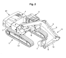
FIG. 2 is a view illustrating the use state of heavy equipment having a tool box opening in forward direction of the equipment according to an embodiment of the present invention; -
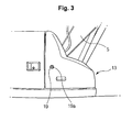
FIG. 3 is a schematic view illustrating the closed state of a tool box door as illustrated inFIG. 2 ; and -
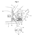
FIG. 4 is a view illustrating the open state of a tool box door as illustrated inFIG. 2 . - Hereinafter, preferred embodiments of the present invention will be described with reference to the accompanying drawings. The matters defined in the description, such as the detailed construction and elements, are nothing but specific details provided to assist those of ordinary skill in the art in a comprehensive understanding of the invention, and thus the present invention is not limited thereto.
- As shown in
FIGS. 2 to 4 , heavy equipment having a tool box opening in forward direction of the equipment according to an embodiment of the present invention includes alower driving structure 1; anupper frame 2 mounted on thelower driving structure 1 to be swiveled; acap 3 and anengine room 4 mounted in front and in the rear of theupper frame 2;working devices 11 including aboom 5 fixed to theupper frame 2, anarm 6, abucket 7, andhydraulic cylinders counter weight 12 mounted in the rear of theupper frame 2 to keep the balance of the equipment during working; atool box door 13 mounted on theupper frame 2 to open from the rear to the front side of the equipment, and formingstorage space 18; and agas spring 20 for opening thetool box door 13 when abutton 19 mounted on an external surface of thetool box door 13 is pressed. - The equipment according to an embodiment of the present invention further includes a damping elastic member 21 (e.g. a tension spring) for preventing an abrupt opening of the
tool box door 13 when thetool box door 13 is opened by thegas spring 20. - The equipment according to an embodiment of the present invention further includes a protection member and an
auxiliary handle 22 mounted on theupper frame 2 to prevent thegas spring 20 and the dampingelastic member 21 from being damaged by an external impact. - The equipment according to an embodiment of the present invention further includes a
foothold 23 for ascending and descending formed on theupper frame 2 so that an operator can ascend to theengine room 4 through stepping on thefoothold 23 when thetool box door 13 is opened. - The equipment according to an embodiment of the present invention further includes an
embossing part 24 formed to project from an upper surface of thefoothold 23 to prevent slipping during ascending or descending. - Through
holes 25 are formed on theembossing part 24. - The equipment according to an embodiment of the present invention further includes a
handle 26 for ascending and descending formed on one side of the foothold 23 (or fixed to a side surface of a hydraulic fluid tank). - Since the construction including the
lower driving structure 1, theupper frame 2, theengine room 4, theworking devices 11, and the like, is substantially the same as that as illustrated inFIG. 1 , the detailed description thereof will be omitted. In the description of the present invention, the same drawing reference numerals are used for the same elements among/across various figures. - Hereinafter, the operation of the heavy equipment having a tool box opening in forward direction of the equipment according to an embodiment of the present invention will be described with reference to accompanying drawings.
- As illustrated in
FIG. 4 , when an operator ascends to an upper part of theengine room 4 in order to confirm the performance of a hydraulic pump and so on installed in theengine room 4 or to repair or replace the corresponding component, thegas spring 20 is extended during the pressing of thebutton 19 installed on the outer surface of thetool box door 13, and thus thetool box door 13 is rotated (clockwise) around a hinge part (e.g. a hinge) fixed to theupper frame 2, and thus thetool box door 13 is opened from the rear to the front side of the equipment. - At this time, the
tool box door 13, which is opened by thegas spring 20, is prevented from being abruptly opened by a tension force of the elastic member (e.g. tension spring) 21. - Accordingly, the operator can ascend to an upper part of the
engine room 4 by stepping on thelower driving structure 1 and thefoothold 23 installed on theupper frame 2 in order. In this case, the operator can hold on to thehandle 26 installed on one side of thefoothold 23, the protection member, and theauxiliary handle 22 to keep safely in ascending. - In the case of ascending the
engine room 4 in the winter season or in the rainy season, the operator is prevented from slipping on thefoothold 23 by the embossingpart 24 projected from the upper surface of thefoothold 23 and the throughholes 25 formed in the center of the embossingpart 24. - In the case of closing the
tool box door 13, thefoothold 23 and thehandle 26 for ascending and descending are accommodated and concealed in thestorage space 18 of thetool box door 13. Accordingly, it is restricted for the operator to ascend to the upper part of theengine room 4 by stepping on the tool box contrary to the operator's intention. - On the other hand, as the "∩" -shaped protection member and the
auxiliary handle 22 are installed on the outside of theelastic member 21 and thegas spring 20, theelastic member 21 and thegas spring 20 are prevented from being damaged by an external impact. Also, in the case of ascending toward theengine room 4 by stepping on thelower driving structure 1, the operator can hold on to the protection member and theauxiliary handle 22 to keep safety in ascending. - As the
tool box door 13 is opened toward the equipment by thegas spring 20 as described above, extendedstorage space 18 can be secured. Voluminous tool box and so on can be accommodated in thestorage space 18 to provide convenience to the operator. - Since it is possible for the operator to ascend to the upper part of the
engine room 4 without stepping on the tool box door 13 (i.e. thetool box door 13 does not serve as a foothold), thetool box door 13 can be prevented from being damaged or deformed. - Also, the size and shape of the
tool box door 13 mounted on theupper frame 2 can be freely changed, and thus the external appearance of the whole equipment can be improved. - On the other hand, by manipulating a key coupled to a
key insertion hole 19a formed in the center of thebutton 19, thetool box door 13 can be locked. Accordingly, even in the case of pressing thebutton 19, thegas spring 20 is prevented from being extended, and thus thetool box door 13 cannot be opened. - As described above, the heavy equipment having a tool box opening in forward direction of the equipment has the following advantages.
- The tool box door mounted on the upper frame can be opened and closed by the button and the gas spring, and the shape of the tool box door can be freely designed to sufficiently secure storage space, so that convenience can be provided to a user.
- In addition, the operator can ascend toward the engine room without directly stepping on the tool box door to prevent the damage and deformation of the tool box door and to lengthen the life span of the tool box door, and an auxiliary structure for safety, such as a handrail, an anti-slip plate, and the like, is unnecessary to reduce the manufacturing cost.
- Although preferred embodiments of the present invention have been described for illustrative purposes, those skilled in the art will appreciate that various modifications, additions and substitutions are possible, without departing from the scope and spirit of the invention as disclosed in the accompanying claims.
Claims (7)
- Heavy equipment having a tool box opening in forward direction of the equipment, comprising:a lower driving structure;an upper frame mounted on the lower driving structure to be swiveled;a cap and an engine room mounted in front and in the rear of the upper frame;working devices including a boom fixed to the upper frame, an arm, a bucket, and hydraulic cylinders for driving the boom, the arm, and the bucket, respectively;a counter weight mounted in the rear of the upper frame to keep the balance of the equipment during working;a tool box door mounted on the upper frame to open from the rear to the front side of the equipment, and forming storage space; anda gas spring for opening the tool box door when a button mounted on an external surface of the tool box door is pressed.
- The heavy equipment of claim 1, further comprising a damping elastic member for preventing an abrupt opening of the tool box door when the tool box door is opened by the gas spring.
- The heavy equipment of claim 2, further comprising a protection member and an auxiliary handle mounted on the upper frame to prevent the gas spring and the damping elastic member from being damaged by an external impact.
- The heavy equipment of claim 3, further comprising a foothold for ascending and descending formed on the upper frame so that an operator can ascend to the engine room through stepping on the foothold when the tool box door is opened.
- The heavy equipment of claim 4, further comprising a handle for ascending and descending formed on one side of the foothold.
- The heavy equipment of claim 5, further comprising an embossing part formed to project from an upper surface of the foothold to prevent slipping during ascending or descending.
- The heavy equipment of claim 6, wherein through holes are formed on the embossing part.
Applications Claiming Priority (1)
| Application Number | Priority Date | Filing Date | Title |
|---|---|---|---|
| KR1020070099269A KR100945190B1 (en) | 2007-10-02 | 2007-10-02 | Heavy equipment with toolbox opening in the forward direction of the machine |
Publications (3)
| Publication Number | Publication Date |
|---|---|
| EP2045399A2 true EP2045399A2 (en) | 2009-04-08 |
| EP2045399A3 EP2045399A3 (en) | 2017-03-01 |
| EP2045399B1 EP2045399B1 (en) | 2023-07-26 |
Family
ID=40262038
Family Applications (1)
| Application Number | Title | Priority Date | Filing Date |
|---|---|---|---|
| EP08016936.0A Ceased EP2045399B1 (en) | 2007-10-02 | 2008-09-26 | Heavy equipment having tool box opening in forward direction of the equipment |
Country Status (5)
| Country | Link |
|---|---|
| US (1) | US7780213B2 (en) |
| EP (1) | EP2045399B1 (en) |
| JP (1) | JP5192959B2 (en) |
| KR (1) | KR100945190B1 (en) |
| CN (1) | CN101403219B (en) |
Cited By (2)
| Publication number | Priority date | Publication date | Assignee | Title |
|---|---|---|---|---|
| EP2474672A4 (en) * | 2009-09-02 | 2017-01-18 | Hitachi Construction Machinery Co., Ltd. | Wheel type working vehicle |
| WO2019038347A1 (en) * | 2017-08-24 | 2019-02-28 | Caterpillar Sarl | Hydraulic shovel |
Families Citing this family (21)
| Publication number | Priority date | Publication date | Assignee | Title |
|---|---|---|---|---|
| JP5152027B2 (en) * | 2009-02-13 | 2013-02-27 | コベルコ建機株式会社 | Toolbox structure |
| CN102667011B (en) * | 2010-01-26 | 2014-07-30 | 株式会社小松制作所 | Engine hood for construction machine |
| KR101037948B1 (en) * | 2010-08-13 | 2011-05-30 | 김석곤 | Car crane driver's seat Kevin |
| JP5600050B2 (en) * | 2010-11-29 | 2014-10-01 | 日立建機株式会社 | Construction machine side camera mounting structure |
| US9366007B2 (en) * | 2012-03-16 | 2016-06-14 | Hitachi Construction Machinery Co., Ltd. | Construction machine |
| RU2601634C1 (en) * | 2012-11-05 | 2016-11-10 | Дир Энд Компани | Integrated door control system and its control method |
| KR101575704B1 (en) * | 2012-11-13 | 2015-12-08 | 가부시키가이샤 고마쓰 세이사쿠쇼 | Hydraulic shovel |
| JP5315481B1 (en) * | 2012-11-13 | 2013-10-16 | 株式会社小松製作所 | Excavator |
| WO2014076764A1 (en) * | 2012-11-13 | 2014-05-22 | 株式会社小松製作所 | Hydraulic shovel |
| JP5949793B2 (en) * | 2014-01-17 | 2016-07-13 | コベルコ建機株式会社 | Construction machinery |
| US9404238B1 (en) * | 2015-01-10 | 2016-08-02 | Bauer Maschinen Gmbh | Construction machine |
| JP6339948B2 (en) * | 2015-02-18 | 2018-06-06 | 住友建機株式会社 | Excavator |
| US9677249B2 (en) * | 2015-02-19 | 2017-06-13 | Komatsu Ltd. | Work vehicle with stowable user support member |
| JP6495082B2 (en) * | 2015-04-17 | 2019-04-03 | 日立建機株式会社 | Construction machinery |
| JP6286101B1 (en) * | 2016-12-27 | 2018-02-28 | 株式会社小松製作所 | Work vehicle |
| CN106968286A (en) * | 2017-03-29 | 2017-07-21 | 湖南高福星智能科技有限公司 | It is a kind of that there is the digging engineering machine for efficiently climbing function |
| DE202017104124U1 (en) | 2017-07-11 | 2017-10-13 | Rheinmetall Landsysteme Gmbh | Storage box for an armored vehicle |
| KR20190002885U (en) | 2018-05-14 | 2019-11-22 | 주식회사구보 | A ToolBox Assembly for Heavy Industry |
| CN110656673A (en) * | 2019-11-12 | 2020-01-07 | 徐州菲诺特德机械设备有限公司 | Excavator toolbox installation mechanism |
| US11525240B2 (en) * | 2020-07-23 | 2022-12-13 | Caterpillar Underground Mining Pty. Ltd. | Storage assembly for battery energizing switches of electric machines |
| JP7622921B2 (en) * | 2021-03-31 | 2025-01-28 | 住友建機株式会社 | Excavator |
Family Cites Families (22)
| Publication number | Priority date | Publication date | Assignee | Title |
|---|---|---|---|---|
| JP2895284B2 (en) * | 1991-10-31 | 1999-05-24 | ヤンマーディーゼル株式会社 | Turning work vehicle |
| JP2591064Y2 (en) * | 1993-03-30 | 1999-02-24 | 油谷重工株式会社 | Tank equipment for construction machinery |
| US5439150A (en) * | 1993-10-21 | 1995-08-08 | Trahms; Kurt R. | Rear window accessible pick up truck storage box |
| JP3107984B2 (en) * | 1994-11-14 | 2000-11-13 | 日立建機株式会社 | Construction machinery |
| JP3288912B2 (en) * | 1995-12-22 | 2002-06-04 | 日立建機株式会社 | Storage box for construction machinery |
| JPH10266264A (en) * | 1997-03-24 | 1998-10-06 | Shin Caterpillar Mitsubishi Ltd | Storage box in construction machine |
| JPH1193215A (en) * | 1997-09-18 | 1999-04-06 | Yutani Heavy Ind Ltd | Step structure of construction machine |
| JP4032106B2 (en) * | 1998-08-31 | 2008-01-16 | ヤンマー株式会社 | Ultra-small turning machine |
| CA2261907A1 (en) * | 1999-02-05 | 2000-08-05 | Joseph Brady | Truck storage box |
| JP3673683B2 (en) * | 1999-09-24 | 2005-07-20 | 株式会社クボタ | Swivel work machine |
| JP2002266377A (en) * | 2001-03-09 | 2002-09-18 | Komatsu Ltd | Fuel supply device for construction machinery |
| JP2004052360A (en) * | 2002-07-19 | 2004-02-19 | Sumitomo (Shi) Construction Machinery Manufacturing Co Ltd | Tool box mounting structure for hydraulic back hoe |
| JP2004116102A (en) * | 2002-09-25 | 2004-04-15 | Komatsu Ltd | Hydraulic excavator tool storage device |
| JP3809954B2 (en) * | 2002-10-23 | 2006-08-16 | 株式会社小松製作所 | Work vehicle with tilt floor |
| US6929303B1 (en) * | 2002-11-21 | 2005-08-16 | Thomas M. Sharples | Truck bed storage apparatus and tonneau cover |
| JP2004190276A (en) * | 2002-12-10 | 2004-07-08 | Shin Caterpillar Mitsubishi Ltd | Handrail in construction machine |
| JP2005112146A (en) * | 2003-10-07 | 2005-04-28 | Ishikawajima Constr Mach Co | Opening/closing cover of fuel tank of work machine |
| KR100541568B1 (en) * | 2003-11-13 | 2006-01-11 | 호봉식 | Work chair safety cover for crane |
| JP2006001597A (en) * | 2004-06-17 | 2006-01-05 | Sumitomo (Shi) Construction Machinery Manufacturing Co Ltd | Storage box |
| US7237636B2 (en) * | 2004-07-01 | 2007-07-03 | Cnh America Llc | Vehicle drive access and storage device |
| US20070158154A1 (en) * | 2006-01-12 | 2007-07-12 | Avm, Inc. | Piston assembly with reduced shuttle |
| JP2007186170A (en) * | 2006-01-16 | 2007-07-26 | Shin Caterpillar Mitsubishi Ltd | Hood opening/closing assistance device |
-
2007
- 2007-10-02 KR KR1020070099269A patent/KR100945190B1/en not_active Expired - Fee Related
-
2008
- 2008-09-24 JP JP2008244788A patent/JP5192959B2/en not_active Expired - Fee Related
- 2008-09-24 US US12/236,713 patent/US7780213B2/en active Active
- 2008-09-26 EP EP08016936.0A patent/EP2045399B1/en not_active Ceased
- 2008-09-27 CN CN2008101671031A patent/CN101403219B/en not_active Expired - Fee Related
Non-Patent Citations (1)
| Title |
|---|
| None * |
Cited By (5)
| Publication number | Priority date | Publication date | Assignee | Title |
|---|---|---|---|---|
| EP2474672A4 (en) * | 2009-09-02 | 2017-01-18 | Hitachi Construction Machinery Co., Ltd. | Wheel type working vehicle |
| WO2019038347A1 (en) * | 2017-08-24 | 2019-02-28 | Caterpillar Sarl | Hydraulic shovel |
| CN111032965A (en) * | 2017-08-24 | 2020-04-17 | 卡特彼勒Sarl | hydraulic excavator |
| CN111032965B (en) * | 2017-08-24 | 2022-03-22 | 卡特彼勒Sarl | Hydraulic excavator |
| US11525241B2 (en) | 2017-08-24 | 2022-12-13 | Caterpillar Sarl | Hydraulic shovel |
Also Published As
| Publication number | Publication date |
|---|---|
| CN101403219A (en) | 2009-04-08 |
| EP2045399B1 (en) | 2023-07-26 |
| EP2045399A3 (en) | 2017-03-01 |
| JP5192959B2 (en) | 2013-05-08 |
| KR20090034103A (en) | 2009-04-07 |
| US7780213B2 (en) | 2010-08-24 |
| US20090084004A1 (en) | 2009-04-02 |
| KR100945190B1 (en) | 2010-03-03 |
| JP2009084999A (en) | 2009-04-23 |
| CN101403219B (en) | 2012-06-20 |
Similar Documents
| Publication | Publication Date | Title |
|---|---|---|
| EP2045399B1 (en) | Heavy equipment having tool box opening in forward direction of the equipment | |
| EP1982864A2 (en) | Seat for heavy equipment having buffer means in forward and backward directions | |
| CN1898447B (en) | construction machinery | |
| US11773566B2 (en) | Cab for work machine and work machine | |
| EP1635016A3 (en) | Vehicle door handle assembly resisting opening under inertial forces | |
| US20110018308A1 (en) | Dressing cover structure in construction machine | |
| KR101831479B1 (en) | Side camera attachment structure for construction machinery | |
| US20150211208A1 (en) | Emergency egress system for a construction machine | |
| US20080251305A1 (en) | Engine hood door including variable door handle | |
| JP7049920B2 (en) | Work machine cab, and work machine | |
| KR101778827B1 (en) | Construction machinery | |
| EP2821567B1 (en) | Cab for construction machine, and construction machine | |
| EP2192240B1 (en) | Footstep for excavator | |
| WO2002070827A1 (en) | Lifting/lowering step structure for construction machines | |
| KR20070037673A (en) | Working machine | |
| US20060261599A1 (en) | Cover lock mechanism | |
| JP4875643B2 (en) | Construction machinery | |
| KR20090034102A (en) | Excavator with hoist installed behind cab | |
| JP2007030602A (en) | Opening/closing hood unlocking device | |
| JPH10292429A (en) | Handrail for construction machine | |
| KR100934946B1 (en) | Excavator with Cab Cap Riser | |
| KR200371342Y1 (en) | Locking device for a front-window of a cap of heavy equipment | |
| KR20090080353A (en) | Heavy construction equipment with a box formed outside the cab | |
| JP4703369B2 (en) | Work machine | |
| KR20100059397A (en) | Lower-frame of excavator of having storage space |
Legal Events
| Date | Code | Title | Description |
|---|---|---|---|
| PUAI | Public reference made under article 153(3) epc to a published international application that has entered the european phase |
Free format text: ORIGINAL CODE: 0009012 |
|
| AK | Designated contracting states |
Kind code of ref document: A2 Designated state(s): AT BE BG CH CY CZ DE DK EE ES FI FR GB GR HR HU IE IS IT LI LT LU LV MC MT NL NO PL PT RO SE SI SK TR |
|
| AX | Request for extension of the european patent |
Extension state: AL BA MK RS |
|
| PUAL | Search report despatched |
Free format text: ORIGINAL CODE: 0009013 |
|
| AK | Designated contracting states |
Kind code of ref document: A3 Designated state(s): AT BE BG CH CY CZ DE DK EE ES FI FR GB GR HR HU IE IS IT LI LT LU LV MC MT NL NO PL PT RO SE SI SK TR |
|
| AX | Request for extension of the european patent |
Extension state: AL BA MK RS |
|
| RIC1 | Information provided on ipc code assigned before grant |
Ipc: E02F 9/08 20060101AFI20170126BHEP |
|
| STAA | Information on the status of an ep patent application or granted ep patent |
Free format text: STATUS: REQUEST FOR EXAMINATION WAS MADE |
|
| 17P | Request for examination filed |
Effective date: 20170818 |
|
| RBV | Designated contracting states (corrected) |
Designated state(s): AT BE BG CH CY CZ DE DK EE ES FI FR GB GR HR HU IE IS IT LI LT LU LV MC MT NL NO PL PT RO SE SI SK TR |
|
| AKX | Designation fees paid |
Designated state(s): DE FR GB IT |
|
| AXX | Extension fees paid |
Extension state: AL Extension state: BA Extension state: MK Extension state: RS |
|
| STAA | Information on the status of an ep patent application or granted ep patent |
Free format text: STATUS: EXAMINATION IS IN PROGRESS |
|
| 17Q | First examination report despatched |
Effective date: 20201119 |
|
| GRAP | Despatch of communication of intention to grant a patent |
Free format text: ORIGINAL CODE: EPIDOSNIGR1 |
|
| STAA | Information on the status of an ep patent application or granted ep patent |
Free format text: STATUS: GRANT OF PATENT IS INTENDED |
|
| INTG | Intention to grant announced |
Effective date: 20230214 |
|
| GRAS | Grant fee paid |
Free format text: ORIGINAL CODE: EPIDOSNIGR3 |
|
| GRAA | (expected) grant |
Free format text: ORIGINAL CODE: 0009210 |
|
| STAA | Information on the status of an ep patent application or granted ep patent |
Free format text: STATUS: THE PATENT HAS BEEN GRANTED |
|
| AK | Designated contracting states |
Kind code of ref document: B1 Designated state(s): DE FR GB IT |
|
| REG | Reference to a national code |
Ref country code: DE Ref legal event code: R096 Ref document number: 602008064821 Country of ref document: DE |
|
| U01 | Request for unitary effect filed |
Effective date: 20230824 |
|
| RAP4 | Party data changed (patent owner data changed or rights of a patent transferred) |
Owner name: VOLVO CONSTRUCTION EQUIPMENT AB |
|
| U04 | Request for unitary effect rejected |
Effective date: 20231019 |
|
| REG | Reference to a national code |
Ref country code: DE Ref legal event code: R097 Ref document number: 602008064821 Country of ref document: DE |
|
| PGFP | Annual fee paid to national office [announced via postgrant information from national office to epo] |
Ref country code: DE Payment date: 20231002 Year of fee payment: 16 |
|
| PG25 | Lapsed in a contracting state [announced via postgrant information from national office to epo] |
Ref country code: IT Free format text: LAPSE BECAUSE OF FAILURE TO SUBMIT A TRANSLATION OF THE DESCRIPTION OR TO PAY THE FEE WITHIN THE PRESCRIBED TIME-LIMIT Effective date: 20230726 |
|
| PLBE | No opposition filed within time limit |
Free format text: ORIGINAL CODE: 0009261 |
|
| STAA | Information on the status of an ep patent application or granted ep patent |
Free format text: STATUS: NO OPPOSITION FILED WITHIN TIME LIMIT |
|
| GBPC | Gb: european patent ceased through non-payment of renewal fee |
Effective date: 20231026 |
|
| 26N | No opposition filed |
Effective date: 20240429 |
|
| PG25 | Lapsed in a contracting state [announced via postgrant information from national office to epo] |
Ref country code: GB Free format text: LAPSE BECAUSE OF NON-PAYMENT OF DUE FEES Effective date: 20231026 |
|
| PG25 | Lapsed in a contracting state [announced via postgrant information from national office to epo] |
Ref country code: GB Free format text: LAPSE BECAUSE OF NON-PAYMENT OF DUE FEES Effective date: 20231026 |
|
| PG25 | Lapsed in a contracting state [announced via postgrant information from national office to epo] |
Ref country code: FR Free format text: LAPSE BECAUSE OF NON-PAYMENT OF DUE FEES Effective date: 20230926 |
|
| PG25 | Lapsed in a contracting state [announced via postgrant information from national office to epo] |
Ref country code: FR Free format text: LAPSE BECAUSE OF NON-PAYMENT OF DUE FEES Effective date: 20230926 |
|
| REG | Reference to a national code |
Ref country code: DE Ref legal event code: R119 Ref document number: 602008064821 Country of ref document: DE |
|
| PG25 | Lapsed in a contracting state [announced via postgrant information from national office to epo] |
Ref country code: DE Free format text: LAPSE BECAUSE OF NON-PAYMENT OF DUE FEES Effective date: 20250401 |