EP2045147A1 - Seat belt system for adults and children - Google Patents
Seat belt system for adults and children Download PDFInfo
- Publication number
- EP2045147A1 EP2045147A1 EP08009918A EP08009918A EP2045147A1 EP 2045147 A1 EP2045147 A1 EP 2045147A1 EP 08009918 A EP08009918 A EP 08009918A EP 08009918 A EP08009918 A EP 08009918A EP 2045147 A1 EP2045147 A1 EP 2045147A1
- Authority
- EP
- European Patent Office
- Prior art keywords
- seat belt
- belt webbing
- strap
- vehicle
- movable
- Prior art date
- Legal status (The legal status is an assumption and is not a legal conclusion. Google has not performed a legal analysis and makes no representation as to the accuracy of the status listed.)
- Granted
Links
- 230000007246 mechanism Effects 0.000 claims description 17
- 230000000452 restraining effect Effects 0.000 claims description 11
- 230000001133 acceleration Effects 0.000 claims description 4
- 239000000463 material Substances 0.000 description 7
- 238000004873 anchoring Methods 0.000 description 3
- 230000000295 complement effect Effects 0.000 description 3
- 239000000853 adhesive Substances 0.000 description 2
- 230000001070 adhesive effect Effects 0.000 description 2
- 239000003302 ferromagnetic material Substances 0.000 description 2
- 238000007373 indentation Methods 0.000 description 2
- 238000009434 installation Methods 0.000 description 2
- 230000000670 limiting effect Effects 0.000 description 2
- 239000002184 metal Substances 0.000 description 2
- 229910052751 metal Inorganic materials 0.000 description 2
- 230000009471 action Effects 0.000 description 1
- 230000008901 benefit Effects 0.000 description 1
- 239000003086 colorant Substances 0.000 description 1
- 230000001010 compromised effect Effects 0.000 description 1
- 230000006378 damage Effects 0.000 description 1
- 230000003116 impacting effect Effects 0.000 description 1
- 230000001771 impaired effect Effects 0.000 description 1
- 230000013011 mating Effects 0.000 description 1
- 150000002739 metals Chemical class 0.000 description 1
- 239000004033 plastic Substances 0.000 description 1
- 229920003023 plastic Polymers 0.000 description 1
- 230000002829 reductive effect Effects 0.000 description 1
- 230000000284 resting effect Effects 0.000 description 1
- 238000000926 separation method Methods 0.000 description 1
- 238000006467 substitution reaction Methods 0.000 description 1
- 230000032258 transport Effects 0.000 description 1
- 238000003466 welding Methods 0.000 description 1
Images


Classifications
-
- B—PERFORMING OPERATIONS; TRANSPORTING
- B60—VEHICLES IN GENERAL
- B60R—VEHICLES, VEHICLE FITTINGS, OR VEHICLE PARTS, NOT OTHERWISE PROVIDED FOR
- B60R22/00—Safety belts or body harnesses in vehicles
- B60R22/18—Anchoring devices
- B60R22/20—Anchoring devices adjustable in position, e.g. in height
Definitions
- the present invention relates to a vehicle occupant safety restraint, particularly a seat belt system that is suitable for restraining vehicle occupants of a wide range of heights including both children and adults.
- a conventional seat belt system comprises a length of seat belt webbing connected at three-points to load-bearing parts of a vehicle.
- the webbing is arranged to have a lap portion that passes laterally across the hips of a seat occupant, and a torso portion that passes diagonally across the torso of the seat occupant from one hip to the opposite shoulder.
- one end of the webbing is attached to a sill anchor that is bolted to a load-bearing longitudinal structural member on one side of the vehicle seat, usually between the vehicle seat and an adjacent door.
- the lap and torso portions join at a buckle mechanism on the opposite side of the vehicle seat.
- the shoulder end of the webbing is attached to a seat belt retractor mounted to a load-bearing part of the vehicle, for example a side pillar or sill, or directly to a load-bearing seat component, optionally via a webbing guide.
- the seat belt retractor increases comfort for the seat occupant restrained by the seat belt by allowing the webbing to pay out under relatively low loads to enable limited movement of the restrained seat occupant, for example to reach in-car entertainment controls or storage compartments.
- the seat belt retractor is biased to keep the webbing relatively taut about the seat occupant and a locking element locks the seat belt retractor against webbing payout in the event an acceleration sensor senses rapid acceleration or deceleration indicative of a vehicle crash.
- the belt webbing is fastened to the buckle mechanism by a buckle tongue that is attached to the webbing such that the buckle tongue can slide along the belt webbing.
- the proportions of the belt webbing making up the lap and torso portions can easily be varied to suit the size of a seat occupant.
- Conventional seat belt systems of this sort tend to be unsuitable for vehicle seat occupants of shorter than average stature, particularly for children, because the shoulder fastening point is fixed at or above the height of the back of the vehicle seat to accommodate an average size person. This is particularly so in seat belt systems for locations in a vehicle other than the front vehicle seats.
- the torso portion of the seat belt tends to be badly positioned for a child or short person and usually passes too close or adjacent to the child's neck. Because the child does not fit into the adult seat belt properly the child's shoulder can roll out of the seat belt during a crash effectively making the seat belt a two-point lap belt only. This is dangerous because the lap portion alone will then take more force in a crash and will be more likely to inflict injuries than when a torso belt section is combined. In addition there is a danger of the child sliding forward under the lap portion.
- GB 2 015 321 A A solution to this problem was proposed in GB 2 015 321 A for a seat belt system product commercially marketed as "The Generation Belt".
- the seat belt system taught in GB 2 015 321 A was designed to improve the comfort of a seat belt system for a child and does not comply with the latest safety regulations of which at least one is ECE 44/03.
- the seat belt system taught in GB 2 015 321 A provides poor comfort for adults because the seat belt webbing cannot be positioned in a direct line across the shoulder of an adult seat occupant without the seat belt webbing being redirected through a movable seat belt webbing guide.
- Fig. 1 is an exploded perspective view of a prior art seat belt system according to GB 2 015 321 A .
- Fig. 2 is a fragmentary sectional side view on a larger scale of a connector of the prior art seat belt system of Fig. 1 .
- Fig. 3 is a diagrammatic side elevation view of the prior art seat belt system of Fig. 1 .
- Fig. 4 is a diagrammatic side elevation view of a seat belt system according to the present invention configured for use by an adult occupying a vehicle seat.
- Fig. 5 is a diagrammatic side elevation view of a seat belt system according to the present invention configured for use by a child occupying a vehicle seat.
- Figs. 6 and 7 are side elevation views of seat belt systems according to the present invention restraining an adult occupying a vehicle seat.
- Fig. 8 is a side elevation view of a seat belt system according to the present invention restraining a child occupying a vehicle seat.
- Fig. 9 is an enlarged cross-sectional view of the movable seat belt webbing guide shown in Figs. 4 through 7 in a locked configuration.
- Fig. 10 is an enlarged cross-sectional view of the movable seat belt webbing guide of in a released configuration.
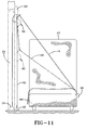
- Fig. 11 is a schematic front elevation view of a seat belt system according to the present invention with some of the components mounted to a side structure of the vehicle rather than to a vehicle seat.
- Fig. 12 is a schematic side elevation view of the prior art seat belt system of Figs. 1 - 3 used by a child during a rapid deceleration of a vehicle.
- Fig. 13 is a schematic side elevation view of a seat belt system of the present invention used by a child during a rapid deceleration of a vehicle.
- Figs. 14-17 are side elevation views, in section, showing the fixation of the movable seat belt webbing guide to the stationary seat belt webbing guide when the seat belt system is configured for use by an adult.
- Fig. 18 is a front perspective view of a stationary seat belt webbing guide of the present invention.
- Fig. 19 is a rear perspective view of a stationary seat belt webbing guide of the present invention.
- Fig. 20 is a perspective view of a movable seat belt webbing guide of the present invention.
- Fig. 20A is an exploded view showing the components of the movable seat belt webbing guide.
- Fig. 21 is a perspective view of the components of another embodiment of the present invention wherein the strap is not permanently attached to a structural member of the seat.
- Fig. 22 shows the embodiment of Fig. 21 with the strap attached to a structural member of the vehicle seat in a detachable manner.
- Fig. 23 shows the embodiment of Figs. 21 and 22 wherein the movable belt webbing guide is spaced from the stationary seat belt webbing guide.
- Fig. 24 is a frontal the embodiment of Figs. 21 and 22 wherein the stationary seat belt webbing guide is mounted to a component of the vehicle other than the vehicle seat such as a pillar supporting the roof of the vehicle with the strap retracted and the seat belt webbing and movable seat belt webbing guide not shown for clarity.
- Fig. 25 shows the embodiment of Fig. 23 with the strap attached to a structural member of the vehicle seat in a detachable manner.
- Fig. 26 is a diagrammatic side view of the seatbelt system of Figs. 21 - 23 .
- Fig 27 is a diagrammatic side view of the seatbelt system of Fig. 25 .
- Fig. 28 is a diagrammatic representation of a portion of a strap with markings indicating proper use of the seat belt system for a child.
- FIG. 1 is an exploded perspective view of a seat belt system 10 having a shoulder belt height adjustment device 11
- Fig. 2 is a sectional side view of the height adjustment device.
- Fig. 3 is a diagrammatic side elevation view of the prior art seat belt system 10 of Fig. 1 .
- a vehicle seat 12 of a typical passenger vehicle in this example a seat other than a front seat, has a seat base 13 and a backrest 14.
- the vehicle seat 12 is provided with a three-point seat belt system 10 having a conventional seat belt retractor 15 secured to any appropriate component of the vehicle, such as the floor 24, a side pillar, the frame of the seat or a parcel shelf located behind the seat.
- the seat belt retractor 15 has a rotatable spool 22 to which a first end 23 of a seat belt webbing 19 is anchored.
- a stationary seat belt webbing guide 16 is secured to any appropriate component of the vehicle by an appropriate fixing means such as a bolt 17, and has a stationary seat belt webbing passageway 18 through which the seat belt webbing 19 passes and is redirected.
- a second end 20 of the seat belt webbing 19 is secured to any appropriate component of the vehicle, such as the floor or the frame of the vehicle seat by an anchor 21.
- the seat belt webbing 19 extends from the rotatable spool 22 such that the seat belt webbing can be wound onto or protracted from the rotatable spool and the length of the seat belt webbing 19 between the rotatable spool 22 and the second end 20 of the seat belt webbing can be varied.
- a seat belt buckle tongue 25 is attached to the seat belt webbing 19 such that the seat belt buckle tongue 25 can slide along the seat belt webbing.
- a seat belt buckle 26 is anchored to any appropriate component of the vehicle, such as the floor.
- the seat belt buckle tongue 25 can mate with the seat belt buckle 26 to provide a three-point seat belt system having a torso portion and a lap portion.
- the upper end of the torso portion of the seat belt webbing 19 is located at the stationary seat belt webbing guide 16. This is appropriate for the shoulder heights of average sized adults, but not to the lesser shoulder heights of children.
- the prior art seat belt system 10 of GB 2 015 321 A provides an adjustment device comprising a strap 27 that may or may not be the same material as the seat belt webbing 19.
- the strap 27 is secured to appropriate components of the vehicle by anchors.
- An upper portion of the strap 27 is secured to the stationary seat belt webbing guide 16.
- a lower portion of the strap 27 is secured to the floor of the vehicle or the vehicle seat frame by the anchor 21 for the second end 20 of the seat belt webbing 19.
- the strap 27 extends along a surface of the backrest 14 in a substantially vertical orientation and is pulled against the backrest 14 using a length adjusting means 28, which can be of any suitable type, provided with the strap in the proximity of the upper anchor for the strap. It is a potential fault of this prior art seat belt system that the strap may not be sufficiently restrained by the length adjusting means, which may prevent the strap from properly restraining a seat occupant in a crash. As will be disclosed herein the seat belt system of the present invention solves this problem.
- a shoulder belt height adjustment device 11 in the form of a four bar link is threaded on the strap 27 as shown in Fig. 2 between the length adjusting means 28 and the anchor 21 at the lower portion of the strap.
- One bar 29 of the shoulder belt height adjustment device 11, which is split, is out of the plane of the other three bars 30, 31, 32 and is placed above the other three bars so as to be placed forwardly of the back rest 14.
- the strap 27 is received over the outer two 30, 32 of the co-planar bars and under the bar 31 between them.
- the shoulder belt height adjustment device 11 is moved along the strap 27, ideally to a suitable height that is just above the shoulder of a seat occupant.
- the diagonally oriented torso portion of the seat belt webbing 19 is then threaded beneath the split bar 29 as shown in Figs.
- the uppermost 30 of the co-planar bars provides a position from which the torso portion of the seat belt webbing extends.
- the position of the shoulder belt height adjustment device 11 would be selectively adjustable along the length of the strap 27 to suit both adult and child seat occupants.
- the prior art seat belt system of GB 2 015 321 A was intended as an aftermarket product to be retrofitted to existing vehicles.
- the comfort for an adult was compromised because the seat belt webbing had to go through the stationary seat belt webbing guide and the shoulder belt height adjustment device that were never vertically aligned.
- This problem has potentially dangerous implications if this prior art seat belt system is installed in a public conveyance, such as a mini-bus that commonly transports both children and adults, because any obstacle to the use of a seat belt system can result in non-use of the seat belt system.
- the seat belt system of the present invention solves this problem.
- FIG. 4 is a diagrammatic side elevation view of the new seat belt system 40 configured for use by an adult occupying a vehicle seat.
- Figs. 6 and 7 are side elevation views of embodiments of the new seat belt system 40 restraining an adult 41 occupying a vehicle seat 12.
- the vehicle seat 12 is a vehicle seat other than a front vehicle seat of a vehicle.
- Fig. 11 is a frontal view of yet another embodiment and may be referred to for understanding the arrangement of the seat belt webbing when the webbing is fixed to a buckle mechanism for a three-point seat belt system.
- a conventional seat belt retractor 15 is attached to a suitable component of a vehicle.
- the seat belt retractor 15 is attached to the floor 24 of the vehicle and in Fig. 6 the seat belt retractor 15 is attached to the framework of a backrest 14 of a vehicle seat 12.
- the seat belt retractor 15 has a rotatable spool 22 to which a first end 23 of a seat belt webbing 19 is anchored.
- a second end 20 of the seat belt webbing 19 is anchored to another component of the vehicle, most commonly the floor 24, by an anchor member 42.
- the seat belt webbing 19 extends from the rotatable spool 22 such that the seat belt webbing can be wound onto or protracted from the rotatable spool and the length of the seat belt webbing between the rotatable spool 22 and the second end 20 of the seat belt webbing 19 can be varied.
- a seat belt buckle tongue 25 is attached to the seat belt webbing 19 such that the seat belt buckle tongue can slide along the seat belt webbing.
- a seat belt buckle 26 is anchored to a component of the vehicle such that the seat belt buckle tongue 25 can mate with the seat belt buckle 26 to provide a three-point seat belt system.
- a stationary seat belt webbing guide 50 is attached to a suitable component of the vehicle.
- Fig. 18 is a front perspective view and Fig. 19 is a rear perspective view of an exemplary stationary seat belt webbing guide 50.
- the stationary seat belt webbing guide 50 is attached to the metal frame of the backrest 14 by a suitable means of attachment such as a bolt 51. Depending upon the particular installation a nut 54 may be used with the bolt 51.
- the stationary seat belt webbing guide 50 is located in the interior of the backrest at the top of the backrest.
- Fig. 7 the stationary seat belt webbing guide 50 is located on the exterior of the backrest at the top of the backrest.
- the stationary seat belt webbing guide 50 has a stationary seat belt webbing passageway 53 through which the seat belt webbing 19 and a strap 55 pass.
- the orientation of the stationary seat belt webbing guide 50 can be adapted by an engineer to be appropriate for the location chosen for the stationary seat belt webbing guide.
- a strap 55 extends substantially vertically along a front surface of the backrest 14, that is to say the surface of the backrest against which the back of a seat occupant rests.
- the strap 55 is preferably the same material as the seat belt webbing 19, but this is not a requirement and the strap may comprise any suitable material.
- An upper end portion 56 of the strap 55 is attached to the stationary seat belt webbing guide 50 at a first anchor 57.
- the first anchor 57 is a rod having its ends firmly fixed to the stationary seat belt webbing guide 50 and the upper end portion 56 of the strap 55 is folded around the rod and the folds of the strap are secured to one another by appropriate means for attachment such as stitching or an adhesive.
- the rod is not shown in Fig. 19 , but it is understood that the ends of the rod would be fit into the slots 61.
- the first anchor 57 that attaches the upper end portion 56 of the strap 55 to the stationary seat belt webbing guide 50 is located vertically lower than the stationary seat belt webbing passageway 53 of the stationary seat belt webbing guide 50 and the strap extends from the first anchor through the seat belt webbing passageway 53.
- a lower end portion 58 of the strap 55 is attached to a component of the vehicle at the anchor member 42. While any suitable means may be employed for attaching the lower end portion 5 of the strap 55 to the anchor member 42, in the illustrated embodiments the anchor member 42 has a slot 59 therein and the lower end portion 58 of the strap 55 extends through the slot.
- the lower end portion 58 of the strap 55 is folded around a portion of the second anchor and the folds of the strap are secured to one another by appropriate means for attachment such as stitching or an adhesive.
- the second anchor 42 is secured to the floor 24 of the vehicle and the anchor member 42 is adapted to serve as an anchor for both the lower end portion 58 of the strap 55 and the second end 20 of the seat belt webbing 19 as shown in Figs. 6 - 8 .
- a central portion 60 of the strap between the anchors 57, 42 is taut.
- the length of the central portion 60 of the strap 55 cannot be adjusted as disclosed in GB 2 015 321 A .
- Fig. 20 is a perspective view of a movable seat belt webbing guide 65.
- a guide element 66 is located at the top of the movable seat belt webbing guide 65.
- the guide element 66 has a seat belt webbing passageway 67 through which the seat belt webbing 19 passes.
- the guide element 66 may be either an extension of, or attached to a backing plate 70, but in the illustrated embodiment the guide element and backing plate are shown as a single piece.
- the angular orientation of the guide element 66 with respect to the backing plate 70 is a function of the configuration of a vehicle in which the new seat belt system is installed and the location in the vehicle where the components of the new seat belt system are installed, so that orientation is best determined by a designer in accordance with good engineering practices.
- the strap 55 extends through the movable seat belt webbing guide 65 via openings 78, 79, 80 provided by the guide element 66, backing plate 70 and housing 77 and is interposed between the backing plate 70 and a movable clamping member 71 that in this exemplary embodiment can pivot about an axis.
- a kinematic design for moving the movable clamping member into and out of a clamping relationship with the strap and backing member may be employed in the new seat belt system.
- the housing 77 is secured to the backing plate 70 by any suitable means for attachment such as screws 68.
- Fig. 9 is an enlarged cross-sectional view of the movable seat belt webbing guide 65 in a locked configuration
- Fig. 10 is an enlarged cross-sectional view of the movable seat belt webbing guide 65 in a released configuration.
- At least one torsion spring 72 provides the clamping force between a serrated clamping surface 75 of the movable clamping member 71 and the backing plate 70 so that the movable clamping member is biased toward the vertically extending strap 55.
- the movable clamping member 71 is pivoted toward the backing plate 70 to clamp the vertically extending strap 55 and secure the movable seat belt webbing guide 65 in an appropriate location above the shoulder of a seat occupant.
- the clamping member 71 is movable between a first position where the strap 55 is not clamped between the clamping member 71 and the backing plate 70 and a second position where the strap is clamped between the clamping member 71 and the backing plate 70.
- the movable seat belt webbing guide 65 is movable along the strap 55 when the clamping member 71 is in the first position. In Fig.
- the movable seat belt webbing guide 65 is shown from the side in a cross-section view, with force being applied to the lever 76 of the movable clamping member 71 such that the movable clamping member 71 is pivoted away from the backing plate 70 toward the housing 77 and no clamping force applied to the substantially vertically extending strap 55, allowing the movable seat belt webbing guide 65 to be moved vertically along the strap 55.
- Fig. 9 shows the movable seat belt webbing guide 65 when no force is applied to the lever 76.
- the movable seat belt webbing guide 65 can move along the strap 55 to such an extent that the seat belt webbing passageway 67 of the movable seat belt webbing guide 65 can be vertically aligned with the stationary seat belt webbing passageway 53 of the stationary seat belt webbing guide 50 as shown in Figs. 4 and 6 to accommodate an adult by allowing the seat belt webbing 19 to pass in a comfortable manner above the shoulder of an adult occupying the vehicle seat 12.
- movable seat belt webbing guide 65 is secured to the stationary seat belt webbing guide 50 in an easily detachable manner when the seat belt webbing passageway 67 of the movable seat belt webbing guide 65 is vertically aligned with the stationary seat belt webbing passageway 53 of the stationary seat belt webbing guide 50.
- Figs. 14 - 17 are side elevation views, in section, showing exemplary features for the fixation of the movable seat belt webbing guide to the stationary seat belt webbing guide when the seat belt system is configured for use by an adult.
- Fig. 14 at least one protrusion 81 on the backing plate engages a complementary indentation 82 on a mating surface of the stationary seat belt webbing guide 50. A small pulling force in the direction indicated by the arrow A will free the movable seat belt webbing guide 65 from the stationary seat belt webbing guide 50.
- a magnet 83 affixed to the stationary seat belt webbing guide 50 holds the backing plate 70 the movable seat belt webbing guide 65 in place when the backing plate comprises a ferromagnetic material.
- the magnet could be affixed to the backing plate and the stationary seat belt webbing guide 50 can comprise a ferromagnetic material. A small pulling force in the direction indicated by the arrow A will free the movable seat belt webbing guide 65 from the stationary seat belt webbing guide 50.
- a catch 85 on the backing plate mates with a complementary ledge 86 on the stationary seat belt webbing guide 50.
- a small rotating and lifting force as indicated by the arrow B will free the movable seat belt webbing guide 65 from the stationary seat belt webbing guide 50.
- a spring 87 biases a latch 88 into a complementary indentation 89 in the backing plate 70 of the movable seat belt webbing guide 65.
- a small pulling force in the direction indicated by the arrow A will free the movable seat belt webbing guide 65 from the stationary seat belt webbing guide 50.
- the force required for separation of the movable seat belt webbing guide 65 from the stationary seat belt webbing guide 50 in each of the foregoing examples be relatively small so that a child occupying a vehicle seat can easily move the movable seat belt webbing guide 65 from the adult configuration to a child accommodating configuration. It follows that the operation of the clamping and unclamping features of the movable seat belt webbing guide 65 should require minimal force for the same reason. Of course, these minimal force requirements will make the new seat belt system more accessible for persons that may have impaired use of their hands.
- Fig. 5 is a diagrammatic side elevation view of the new seat belt system configured for use by a child occupying a vehicle seat.
- Fig. 8 is a side elevation view of the new seat belt system restraining a child 43 occupying a vehicle seat 12.
- the movable seat belt webbing guide 65 can be moved along the strap 55, as described above, such that the seat belt webbing passageway of the movable seat belt webbing guide 65 is vertically spaced from the seat belt webbing passageway 53 of the stationary seat belt webbing guide 50.
- the new seat belt system can restrain seat occupants of varying heights in a comfortable manner regardless of the height of a shoulder of the seat occupant by adjusting the location of the movable seat belt webbing guide 65 along the strap 55.
- a seat belt system of the present invention provides not only increased comfort for a seat occupant but also prevents the seat belt webbing from resting against the neck area of a child or small seat occupant. This is critical when the seat belt system includes a retractor pretensioner that when activated in a crash very rapidly winds up part of the seat belt webbing, which action would otherwise cause the seat belt webbing to abrade the skin of the seat occupant's neck during the pretensioning operation.
- both the stationary seat belt webbing guide 50 and the anchor member 42, to which the lower end portion 58 of the strap 55 is attached are both attached to a structural component 91 of the vehicle located at a longitudinally extending side of the vehicle.
- the structural component 91 of the vehicle located at a longitudinally extending side of the vehicle may be a pillar supporting the roof of the vehicle displaced laterally from the vehicle seat 12.
- the second end of the seat belt webbing 19 is anchored to a structural member of the vehicle seat 12 by a separate anchor member 90.
- the components of the new seat belt system in this side mounted embodiment are substantially the same as in the other embodiments and function in the same manner.
- the configuration for an adult is shown with solid lines while the configuration for a child is shown with dashed lines.
- Fig. 12 shows a child 43 restrained by the prior art seat belt system of GB 2 015 321 A . Because the prior art seat belt system of GB 2 015 321 A uses a four bar shoulder belt height adjustment device 11 the strap 27 has to be loose so that the shoulder belt height adjustment device can easily be moved along the strap. The loose strap 27 allows seat belt webbing 19 restraining the child 43 to move forward in the vehicle seat 12 an excessive distance to possibly impact a structure of the interior of the vehicle with a possibility that the child's shoulder may roll out of the seat belt. These same phenomena may occur with an adult seat occupant. However, in Fig.
- the strap 55 of the new seat belt system is taut and anchored in a non-adjustable manner so the forward movement of the child 43 in the vehicle seat 12, or adult seat occupant, is more restricted by the seat belt webbing 19 to prevent the seat occupant from possibly impacting a structure of the interior of the vehicle.
- the strap may be made a variable feature of the seat belt system as illustrated in Figs. 21 to 27 .
- This issue can be addressed by a seat belt system wherein the first anchor to which the upper end portion of the strap 55 is attached is a strap retractor mechanism 63 and the lower end portion of the strap 55 is attached to a fastening member 34, 44 that is detachably fixed to a second anchor 37, 48 which is attached to a structural member 73 of the vehicle seat 12 or a structural member 84 of the vehicle and the strap is be retracted towards the strap retractor mechanism 63 when the fastening member 34, 44 is detached from the second anchor 37, 48.
- the strap retractor mechanism preferably should have automatic locking and emergency locking features known from seat belt retractors as disclosed for example in GB 2 131 279 A or EP 0 267 294 A1 .
- the strap retractor mechanism 63 is installed at a location below the stationary seat belt webbing guide 50.
- the strap 55 is wound upon a rotatable spool of the strap retractor mechanism 63.
- a strap passageway in the stationary seat belt webbing guide 50 directs the strap in a substantially vertical orientation.
- a fastening member 34, 44 is attached to an end of the strap. When the strap is protracted from the spool of the strap retractor mechanism 63 it is pulled downward to allow the fastening member 34, 44 to mate with a second anchor 37, 48 in a removable manner.
- the fastening member at the end of the strap 55 is a strap anchor plate 44 having a keyhole shaped opening therein 45.
- the keyhole shaped opening 45 is an opening having a portion that is a slot in communication with a portion that is wider than the slot.
- the second anchor is a rivet type anchor peg 48 with an annular groove 49 and enlarged head 49 is fixed to either a structural member 75 of the seat or a structural member of the vehicle, such as the floor.
- a closed loop 47 in the strap 55 extends through a strap receiving slot 46 in the strap anchor plate 44 to attach the strap 55 to the strap anchor plate 44.
- the strap 55 may be retracted by the strap retractor mechanism 63 as shown in Fig. 21 if the seat occupant so desires for reasons of personal preference.
- the lower end 30 of the seat belt webbing fixed to an anchor member 42 that is in turn fixed to the floor 84 of the vehicle.
- a seat belt buckle tongue 25 can slide along the seat belt webbing to an appropriate location.
- the movable seat belt webbing guide 65 is adjacent to and fixed to the stationary seat belt webbing guide 50 as described above and the seat belt webbing 19 can be protracted from the seat belt retractor 15 to provide a three point seat belt as described above.
- the strap 55 may be protracted from the strap retractor mechanism 63 as shown in Fig. 22 .
- the wide portion of the keyhole shaped opening 45 in the strap anchor plate 44 is slipped over the head 39 of the anchor peg 48 and aligned with the annular groove 49 in the anchor peg which is secured to the seat belt frame 75 in any appropriate manner such as welding or a threaded fastener mechanism.
- the strap retractor mechanism 63 retracts a portion of the strap to remove slack and the narrow portion of the keyhole shaped slot 45 the strap anchor plate 44 mates with the annular groove 49 of the anchor peg 48 to secure the strap in a substantially vertical orientation.
- the seat belt webbing guide 65 can then be slid along the strap 55 to direct the seat belt webbing 19 in the manner described above regarding other embodiments.
- the fastening member at the end of the strap is a buckle tongue 34 that may be inserted into a buckle 37 for the strap and secured in the buckle.
- the buckle tongue 34 may be released from the buckle 37 using a release mechanism activated by a button 90.
- a closed loop 35 in the strap 55 extends through a strap receiving slot 36 in the buckle tongue 34 to attach the strap 55 to the buckle tongue.
- a buckle anchor strap 35 has a loop 38 that extends through a slot 38 in a portion of the buckle 37.
- the buckle anchor strap 35 is shown fixed to a strap anchor member 52 that is in turn fixed to the floor 84 of the vehicle. With the exception of the substitution of the tongue and buckle as an anchoring system for the strap, this embodiment functions like the embodiment of Figs. 21 - 24 and 26 .
- a tongue receiving passage of the strap buckle 37 should be of a size that will not mate with the buckle tongue 25 of the seat belt in a locking manner, and the buckle tongue 34 fixed to the strap 55 should be of a size that it cannot be accommodated by the buckle of the seat belt in a locking manner.
- the movable seat belt webbing guide interacts with the strap in the same manner described with respect to Figs. 4 10 and 12 - 20A . If the occupant of a seat equipped with the new seat belt system is large enough that the movable seat belt webbing guide can be secured to the stationary seat belt webbing guide as described above with respect to Figs. 14 - 17 , the strap can be unfastened from the anchoring member and allowed to be wound up on the retractor with only a short length of the strap extending through the strap passageway in the stationary seat belt webbing guide as shown in Fig. 21 .
- the seat belt system can then function as a well known three point seat belt system as described above with respect to Figs. 4 , 6 and 7 .
- the strap can easily be withdrawn from the spool of the retractor and the fastening member fixed to the anchoring member in a removable manner.
- the movable seat belt webbing guide can then be moved along the strap as described with respect to Figs. 4-10 and 12 - 20A .
- a seat belt system of any embodiment of the present invention may be provided with a pretensioning device that reduces slack from the seat belt webbing when a significant deceleration of the vehicle is detected by an acceleration sensor.
- Pretensioning can be provided by a retractor pretensioner which is a seat belt retractor provided with a pretensioning mechanism as taught for example in EP 0 952 049 B1 and EP 0 827 883 B1 .
- the seat belt system could be provided with a buckle pretensioner that reduces slack from the seat belt webbing by pulling on the seat belt buckle, as taught for example in EP 0 984 875 B1 .
- a seat belt system of any embodiment of the present invention may be provided with a load limiting feature that reduces the load placed on a seat occupant by the seat belt webbing during a crash when the seat belt retractor spool has been locked against rotation.
- a way of providing the seat belt system with a load limiting capability is to have at least a part of the strap 55 comprised of a load levelling extendable material.
- the generally vertically extending strap 55 comprises two sections 91, 92.
- the lower section 91 is formed of extendable material such as will extend elastically or alternatively plastically under a predetermined force.
- the upper section 92 is non-extendable, for example conventional seat belt webbing material.
- Extendable webbing for safety restraint seat belts usable for the lower extendable portion 91 is disclosed for example, yarn as taught for example in WO 98/41427 A1 , WO 2005/071147 A1 , US 4 710 423 A and US 5 830 811 A .
- Such elongatable webbing can be woven, knitted or sewn to conventional non-extendable webbing to make a generally vertically extending strap according to the invention.
- Fig. 28 shows a portion 74 of a strap 55 with provided with markings 74, such as colours or symbols or words, or a combination thereof, that indicate the location on the strap to which the movable seat belt webbing guide 65 may be attached when the seat belt system is restraining a child, especially a child that is not seated upon a booster cushion.
- a stop 62 is formed on the strap 55 to serve as an indicator of the lower limit of the intended range of locations for the movable seat belt webbing guide 65.
- the components of the new seat belt system can be made of any suitable materials, such as metals or plastics, selected in accordance with good engineering practices.
Landscapes
- Engineering & Computer Science (AREA)
- Mechanical Engineering (AREA)
- Automotive Seat Belt Assembly (AREA)
Abstract
Description
- The present invention relates to a vehicle occupant safety restraint, particularly a seat belt system that is suitable for restraining vehicle occupants of a wide range of heights including both children and adults.
- A conventional seat belt system comprises a length of seat belt webbing connected at three-points to load-bearing parts of a vehicle. The webbing is arranged to have a lap portion that passes laterally across the hips of a seat occupant, and a torso portion that passes diagonally across the torso of the seat occupant from one hip to the opposite shoulder.
- Typically one end of the webbing is attached to a sill anchor that is bolted to a load-bearing longitudinal structural member on one side of the vehicle seat, usually between the vehicle seat and an adjacent door. The lap and torso portions join at a buckle mechanism on the opposite side of the vehicle seat. The shoulder end of the webbing is attached to a seat belt retractor mounted to a load-bearing part of the vehicle, for example a side pillar or sill, or directly to a load-bearing seat component, optionally via a webbing guide.
- The seat belt retractor increases comfort for the seat occupant restrained by the seat belt by allowing the webbing to pay out under relatively low loads to enable limited movement of the restrained seat occupant, for example to reach in-car entertainment controls or storage compartments. The seat belt retractor is biased to keep the webbing relatively taut about the seat occupant and a locking element locks the seat belt retractor against webbing payout in the event an acceleration sensor senses rapid acceleration or deceleration indicative of a vehicle crash.
- The belt webbing is fastened to the buckle mechanism by a buckle tongue that is attached to the webbing such that the buckle tongue can slide along the belt webbing. The proportions of the belt webbing making up the lap and torso portions can easily be varied to suit the size of a seat occupant.
- Conventional seat belt systems of this sort tend to be unsuitable for vehicle seat occupants of shorter than average stature, particularly for children, because the shoulder fastening point is fixed at or above the height of the back of the vehicle seat to accommodate an average size person. This is particularly so in seat belt systems for locations in a vehicle other than the front vehicle seats. The torso portion of the seat belt tends to be badly positioned for a child or short person and usually passes too close or adjacent to the child's neck. Because the child does not fit into the adult seat belt properly the child's shoulder can roll out of the seat belt during a crash effectively making the seat belt a two-point lap belt only. This is dangerous because the lap portion alone will then take more force in a crash and will be more likely to inflict injuries than when a torso belt section is combined. In addition there is a danger of the child sliding forward under the lap portion.
- It is well known that a child may feel uncomfortable with adult seat belt restraints and may position the torso portion behind their back to reduce discomfort. A solution to this problem was proposed in
GB 2 015 321 A GB 2 015 321 A GB 2 015 321 A - The need for a seat belt system for restraining both adults and children in a convenient and comfortable manner is met by a seat belt system according to the present invention as set forth in
Claim 1. -
Fig. 1 is an exploded perspective view of a prior art seat belt system according toGB 2 015 321 A -
Fig. 2 is a fragmentary sectional side view on a larger scale of a connector of the prior art seat belt system ofFig. 1 . -
Fig. 3 is a diagrammatic side elevation view of the prior art seat belt system ofFig. 1 . -
Fig. 4 is a diagrammatic side elevation view of a seat belt system according to the present invention configured for use by an adult occupying a vehicle seat. -
Fig. 5 is a diagrammatic side elevation view of a seat belt system according to the present invention configured for use by a child occupying a vehicle seat. -
Figs. 6 and7 are side elevation views of seat belt systems according to the present invention restraining an adult occupying a vehicle seat. -
Fig. 8 is a side elevation view of a seat belt system according to the present invention restraining a child occupying a vehicle seat. -
Fig. 9 is an enlarged cross-sectional view of the movable seat belt webbing guide shown inFigs. 4 through 7 in a locked configuration. -
Fig. 10 is an enlarged cross-sectional view of the movable seat belt webbing guide of in a released configuration. -
Fig. 11 is a schematic front elevation view of a seat belt system according to the present invention with some of the components mounted to a side structure of the vehicle rather than to a vehicle seat. -
Fig. 12 is a schematic side elevation view of the prior art seat belt system ofFigs. 1 - 3 used by a child during a rapid deceleration of a vehicle. -
Fig. 13 is a schematic side elevation view of a seat belt system of the present invention used by a child during a rapid deceleration of a vehicle. -
Figs. 14-17 are side elevation views, in section, showing the fixation of the movable seat belt webbing guide to the stationary seat belt webbing guide when the seat belt system is configured for use by an adult. -
Fig. 18 is a front perspective view of a stationary seat belt webbing guide of the present invention. -
Fig. 19 is a rear perspective view of a stationary seat belt webbing guide of the present invention. -
Fig. 20 is a perspective view of a movable seat belt webbing guide of the present invention. -
Fig. 20A is an exploded view showing the components of the movable seat belt webbing guide. -
Fig. 21 is a perspective view of the components of another embodiment of the present invention wherein the strap is not permanently attached to a structural member of the seat. -
Fig. 22 shows the embodiment ofFig. 21 with the strap attached to a structural member of the vehicle seat in a detachable manner. -
Fig. 23 shows the embodiment ofFigs. 21 and22 wherein the movable belt webbing guide is spaced from the stationary seat belt webbing guide. -
Fig. 24 is a frontal the embodiment ofFigs. 21 and22 wherein the stationary seat belt webbing guide is mounted to a component of the vehicle other than the vehicle seat such as a pillar supporting the roof of the vehicle with the strap retracted and the seat belt webbing and movable seat belt webbing guide not shown for clarity. -
Fig. 25 shows the embodiment ofFig. 23 with the strap attached to a structural member of the vehicle seat in a detachable manner. -
Fig. 26 is a diagrammatic side view of the seatbelt system ofFigs. 21 - 23 . -
Fig 27 is a diagrammatic side view of the seatbelt system ofFig. 25 . -
Fig. 28 is a diagrammatic representation of a portion of a strap with markings indicating proper use of the seat belt system for a child. - A currently commercially marketed seat belt system according to
GB 2 015 321 A Figs. 1 - 3 .Fig. 1 is an exploded perspective view of aseat belt system 10 having a shoulder beltheight adjustment device 11, andFig. 2 is a sectional side view of the height adjustment device.Fig. 3 is a diagrammatic side elevation view of the prior artseat belt system 10 ofFig. 1 . - A
vehicle seat 12 of a typical passenger vehicle, in this example a seat other than a front seat, has aseat base 13 and abackrest 14. Thevehicle seat 12 is provided with a three-pointseat belt system 10 having a conventionalseat belt retractor 15 secured to any appropriate component of the vehicle, such as thefloor 24, a side pillar, the frame of the seat or a parcel shelf located behind the seat. Theseat belt retractor 15 has arotatable spool 22 to which afirst end 23 of aseat belt webbing 19 is anchored. - A stationary seat
belt webbing guide 16 is secured to any appropriate component of the vehicle by an appropriate fixing means such as abolt 17, and has a stationary seatbelt webbing passageway 18 through which the seat belt webbing 19 passes and is redirected. Asecond end 20 of theseat belt webbing 19 is secured to any appropriate component of the vehicle, such as the floor or the frame of the vehicle seat by ananchor 21. Theseat belt webbing 19 extends from therotatable spool 22 such that the seat belt webbing can be wound onto or protracted from the rotatable spool and the length of theseat belt webbing 19 between therotatable spool 22 and thesecond end 20 of the seat belt webbing can be varied. A seatbelt buckle tongue 25 is attached to theseat belt webbing 19 such that the seatbelt buckle tongue 25 can slide along the seat belt webbing. Aseat belt buckle 26 is anchored to any appropriate component of the vehicle, such as the floor. The seatbelt buckle tongue 25 can mate with theseat belt buckle 26 to provide a three-point seat belt system having a torso portion and a lap portion. - In the prior art seat belt system of
Fig. 1 the upper end of the torso portion of theseat belt webbing 19 is located at the stationary seatbelt webbing guide 16. This is appropriate for the shoulder heights of average sized adults, but not to the lesser shoulder heights of children. The prior artseat belt system 10 ofGB 2 015 321 A strap 27 that may or may not be the same material as theseat belt webbing 19. Thestrap 27 is secured to appropriate components of the vehicle by anchors. An upper portion of thestrap 27 is secured to the stationary seatbelt webbing guide 16. A lower portion of thestrap 27 is secured to the floor of the vehicle or the vehicle seat frame by theanchor 21 for thesecond end 20 of theseat belt webbing 19. Thestrap 27 extends along a surface of thebackrest 14 in a substantially vertical orientation and is pulled against thebackrest 14 using a length adjusting means 28, which can be of any suitable type, provided with the strap in the proximity of the upper anchor for the strap. It is a potential fault of this prior art seat belt system that the strap may not be sufficiently restrained by the length adjusting means, which may prevent the strap from properly restraining a seat occupant in a crash. As will be disclosed herein the seat belt system of the present invention solves this problem. - A shoulder belt
height adjustment device 11 in the form of a four bar link is threaded on thestrap 27 as shown inFig. 2 between the length adjusting means 28 and theanchor 21 at the lower portion of the strap. Onebar 29 of the shoulder beltheight adjustment device 11, which is split, is out of the plane of the other threebars back rest 14. Thestrap 27 is received over the outer two 30, 32 of the co-planar bars and under thebar 31 between them. In use the shoulder beltheight adjustment device 11 is moved along thestrap 27, ideally to a suitable height that is just above the shoulder of a seat occupant. The diagonally oriented torso portion of theseat belt webbing 19 is then threaded beneath thesplit bar 29 as shown inFigs. 1 and 2 . The uppermost 30 of the co-planar bars provides a position from which the torso portion of the seat belt webbing extends. Ideally the position of the shoulder beltheight adjustment device 11 would be selectively adjustable along the length of thestrap 27 to suit both adult and child seat occupants. - The prior art seat belt system of
GB 2 015 321 A - A seat belt system according to the present invention is shown in
Figs. 4-8 .Fig. 4 is a diagrammatic side elevation view of the newseat belt system 40 configured for use by an adult occupying a vehicle seat.Figs. 6 and7 are side elevation views of embodiments of the newseat belt system 40 restraining anadult 41 occupying avehicle seat 12. In all of the examples presented herein thevehicle seat 12 is a vehicle seat other than a front vehicle seat of a vehicle.Fig. 11 is a frontal view of yet another embodiment and may be referred to for understanding the arrangement of the seat belt webbing when the webbing is fixed to a buckle mechanism for a three-point seat belt system. A conventionalseat belt retractor 15 is attached to a suitable component of a vehicle. InFigs. 4 and7 theseat belt retractor 15 is attached to thefloor 24 of the vehicle and inFig. 6 theseat belt retractor 15 is attached to the framework of abackrest 14 of avehicle seat 12. Theseat belt retractor 15 has arotatable spool 22 to which afirst end 23 of aseat belt webbing 19 is anchored. Asecond end 20 of theseat belt webbing 19 is anchored to another component of the vehicle, most commonly thefloor 24, by ananchor member 42. Theseat belt webbing 19 extends from therotatable spool 22 such that the seat belt webbing can be wound onto or protracted from the rotatable spool and the length of the seat belt webbing between therotatable spool 22 and thesecond end 20 of theseat belt webbing 19 can be varied. A seatbelt buckle tongue 25 is attached to theseat belt webbing 19 such that the seat belt buckle tongue can slide along the seat belt webbing. Aseat belt buckle 26 is anchored to a component of the vehicle such that the seatbelt buckle tongue 25 can mate with theseat belt buckle 26 to provide a three-point seat belt system. - A stationary seat
belt webbing guide 50 is attached to a suitable component of the vehicle.Fig. 18 is a front perspective view andFig. 19 is a rear perspective view of an exemplary stationary seatbelt webbing guide 50. In the embodiments ofFigs. 6 and7 the stationary seatbelt webbing guide 50 is attached to the metal frame of thebackrest 14 by a suitable means of attachment such as abolt 51. Depending upon the particular installation anut 54 may be used with thebolt 51. InFig. 6 the stationary seatbelt webbing guide 50 is located in the interior of the backrest at the top of the backrest. InFig. 7 the stationary seatbelt webbing guide 50 is located on the exterior of the backrest at the top of the backrest. - The stationary seat
belt webbing guide 50 has a stationary seatbelt webbing passageway 53 through which theseat belt webbing 19 and astrap 55 pass. The orientation of the stationary seatbelt webbing guide 50 can be adapted by an engineer to be appropriate for the location chosen for the stationary seat belt webbing guide. - In the embodiments of
Figs. 4 - 8 , astrap 55 extends substantially vertically along a front surface of thebackrest 14, that is to say the surface of the backrest against which the back of a seat occupant rests. Thestrap 55 is preferably the same material as theseat belt webbing 19, but this is not a requirement and the strap may comprise any suitable material. Anupper end portion 56 of thestrap 55 is attached to the stationary seatbelt webbing guide 50 at afirst anchor 57. While any suitable means may be employed for attaching theupper end portion 56 of thestrap 55 to the stationary seatbelt webbing guide 50, in the illustrated embodiment thefirst anchor 57 is a rod having its ends firmly fixed to the stationary seatbelt webbing guide 50 and theupper end portion 56 of thestrap 55 is folded around the rod and the folds of the strap are secured to one another by appropriate means for attachment such as stitching or an adhesive. The rod is not shown inFig. 19 , but it is understood that the ends of the rod would be fit into theslots 61. In these embodiments thefirst anchor 57 that attaches theupper end portion 56 of thestrap 55 to the stationary seatbelt webbing guide 50 is located vertically lower than the stationary seatbelt webbing passageway 53 of the stationary seatbelt webbing guide 50 and the strap extends from the first anchor through the seatbelt webbing passageway 53. Alower end portion 58 of thestrap 55 is attached to a component of the vehicle at theanchor member 42. While any suitable means may be employed for attaching the lower end portion 5 of thestrap 55 to theanchor member 42, in the illustrated embodiments theanchor member 42 has aslot 59 therein and thelower end portion 58 of thestrap 55 extends through the slot. Thelower end portion 58 of thestrap 55 is folded around a portion of the second anchor and the folds of the strap are secured to one another by appropriate means for attachment such as stitching or an adhesive. In these embodiments thesecond anchor 42 is secured to thefloor 24 of the vehicle and theanchor member 42 is adapted to serve as an anchor for both thelower end portion 58 of thestrap 55 and thesecond end 20 of theseat belt webbing 19 as shown inFigs. 6 - 8 . - In the present invention a
central portion 60 of the strap between theanchors central portion 60 of thestrap 55 cannot be adjusted as disclosed inGB 2 015 321 A - The working of the movable seat
belt webbing guide 65 shown inFigs. 4 through 7 is best described with reference toFigs. 9 ,10 and20A . For clarityFig. 20 is a perspective view of a movable seatbelt webbing guide 65. Aguide element 66 is located at the top of the movable seatbelt webbing guide 65. Theguide element 66 has a seatbelt webbing passageway 67 through which theseat belt webbing 19 passes. Theguide element 66 may be either an extension of, or attached to abacking plate 70, but in the illustrated embodiment the guide element and backing plate are shown as a single piece. The angular orientation of theguide element 66 with respect to thebacking plate 70 is a function of the configuration of a vehicle in which the new seat belt system is installed and the location in the vehicle where the components of the new seat belt system are installed, so that orientation is best determined by a designer in accordance with good engineering practices. As best shown inFigs. 9 and10 thestrap 55 extends through the movable seatbelt webbing guide 65 viaopenings guide element 66, backingplate 70 andhousing 77 and is interposed between thebacking plate 70 and amovable clamping member 71 that in this exemplary embodiment can pivot about an axis. However, it should be understood that any kinematic design for moving the movable clamping member into and out of a clamping relationship with the strap and backing member may be employed in the new seat belt system. Thehousing 77 is secured to thebacking plate 70 by any suitable means for attachment such as screws 68.Fig. 9 is an enlarged cross-sectional view of the movable seatbelt webbing guide 65 in a locked configuration andFig. 10 is an enlarged cross-sectional view of the movable seatbelt webbing guide 65 in a released configuration. At least onetorsion spring 72 provides the clamping force between aserrated clamping surface 75 of themovable clamping member 71 and thebacking plate 70 so that the movable clamping member is biased toward the vertically extendingstrap 55. Themovable clamping member 71 is pivoted toward thebacking plate 70 to clamp the vertically extendingstrap 55 and secure the movable seatbelt webbing guide 65 in an appropriate location above the shoulder of a seat occupant. The clampingmember 71 is movable between a first position where thestrap 55 is not clamped between the clampingmember 71 and thebacking plate 70 and a second position where the strap is clamped between the clampingmember 71 and thebacking plate 70. The movable seatbelt webbing guide 65 is movable along thestrap 55 when the clampingmember 71 is in the first position. InFig. 10 the movable seatbelt webbing guide 65 is shown from the side in a cross-section view, with force being applied to thelever 76 of themovable clamping member 71 such that themovable clamping member 71 is pivoted away from thebacking plate 70 toward thehousing 77 and no clamping force applied to the substantially vertically extendingstrap 55, allowing the movable seatbelt webbing guide 65 to be moved vertically along thestrap 55.Fig. 9 shows the movable seatbelt webbing guide 65 when no force is applied to thelever 76. - It is essential that the movable seat
belt webbing guide 65 can move along thestrap 55 to such an extent that the seatbelt webbing passageway 67 of the movable seatbelt webbing guide 65 can be vertically aligned with the stationary seatbelt webbing passageway 53 of the stationary seatbelt webbing guide 50 as shown inFigs. 4 and6 to accommodate an adult by allowing theseat belt webbing 19 to pass in a comfortable manner above the shoulder of an adult occupying thevehicle seat 12. - Preferably the movable seat
belt webbing guide 65 is secured to the stationary seatbelt webbing guide 50 in an easily detachable manner when the seatbelt webbing passageway 67 of the movable seatbelt webbing guide 65 is vertically aligned with the stationary seatbelt webbing passageway 53 of the stationary seatbelt webbing guide 50.Figs. 14 - 17 are side elevation views, in section, showing exemplary features for the fixation of the movable seat belt webbing guide to the stationary seat belt webbing guide when the seat belt system is configured for use by an adult. - In
Fig. 14 at least oneprotrusion 81 on the backing plate engages acomplementary indentation 82 on a mating surface of the stationary seatbelt webbing guide 50. A small pulling force in the direction indicated by the arrow A will free the movable seat belt webbing guide 65 from the stationary seatbelt webbing guide 50. - In
Fig. 15 amagnet 83 affixed to the stationary seatbelt webbing guide 50 holds thebacking plate 70 the movable seatbelt webbing guide 65 in place when the backing plate comprises a ferromagnetic material. Of course, the magnet could be affixed to the backing plate and the stationary seatbelt webbing guide 50 can comprise a ferromagnetic material. A small pulling force in the direction indicated by the arrow A will free the movable seat belt webbing guide 65 from the stationary seatbelt webbing guide 50. - In
Fig. 16 acatch 85 on the backing plate mates with acomplementary ledge 86 on the stationary seatbelt webbing guide 50. A small rotating and lifting force as indicated by the arrow B will free the movable seat belt webbing guide 65 from the stationary seatbelt webbing guide 50. - In
Fig. 17 aspring 87 biases alatch 88 into acomplementary indentation 89 in thebacking plate 70 of the movable seatbelt webbing guide 65. A small pulling force in the direction indicated by the arrow A will free the movable seat belt webbing guide 65 from the stationary seatbelt webbing guide 50. - It is important that the force required for separation of the movable seat belt webbing guide 65 from the stationary seat
belt webbing guide 50 in each of the foregoing examples be relatively small so that a child occupying a vehicle seat can easily move the movable seat belt webbing guide 65 from the adult configuration to a child accommodating configuration. It follows that the operation of the clamping and unclamping features of the movable seatbelt webbing guide 65 should require minimal force for the same reason. Of course, these minimal force requirements will make the new seat belt system more accessible for persons that may have impaired use of their hands. - The use of a seat belt system according to the present invention for a child, or shorter adult is best explained with reference to
Figs. 5 and8 .Fig. 5 is a diagrammatic side elevation view of the new seat belt system configured for use by a child occupying a vehicle seat.Fig. 8 is a side elevation view of the new seat belt system restraining achild 43 occupying avehicle seat 12. As shown the movable seatbelt webbing guide 65 can be moved along thestrap 55, as described above, such that the seat belt webbing passageway of the movable seatbelt webbing guide 65 is vertically spaced from the seatbelt webbing passageway 53 of the stationary seatbelt webbing guide 50. The new seat belt system can restrain seat occupants of varying heights in a comfortable manner regardless of the height of a shoulder of the seat occupant by adjusting the location of the movable seatbelt webbing guide 65 along thestrap 55. - An important advantage of a seat belt system of the present invention is that it provides not only increased comfort for a seat occupant but also prevents the seat belt webbing from resting against the neck area of a child or small seat occupant. This is critical when the seat belt system includes a retractor pretensioner that when activated in a crash very rapidly winds up part of the seat belt webbing, which action would otherwise cause the seat belt webbing to abrade the skin of the seat occupant's neck during the pretensioning operation.
- While the embodiments of the new seat belt system shown in
Figs. 4 through 8 have the stationary seatbelt webbing guide 50 attached to the frame of a backrest of a vehicle seat, in an alternative embodiment shown inFig. 11 both the stationary seatbelt webbing guide 50 and theanchor member 42, to which thelower end portion 58 of thestrap 55 is attached, are both attached to astructural component 91 of the vehicle located at a longitudinally extending side of the vehicle. For example, thestructural component 91 of the vehicle located at a longitudinally extending side of the vehicle may be a pillar supporting the roof of the vehicle displaced laterally from thevehicle seat 12. In this exemplary embodiment the second end of theseat belt webbing 19 is anchored to a structural member of thevehicle seat 12 by aseparate anchor member 90. The components of the new seat belt system in this side mounted embodiment are substantially the same as in the other embodiments and function in the same manner. The configuration for an adult is shown with solid lines while the configuration for a child is shown with dashed lines. - The criticality of the taut condition of the
central portion 60 of thestrap 55 is best understood by referring briefly toFigs 12 and 13. Fig. 12 shows achild 43 restrained by the prior art seat belt system ofGB 2 015 321 A GB 2 015 321 A height adjustment device 11 thestrap 27 has to be loose so that the shoulder belt height adjustment device can easily be moved along the strap. Theloose strap 27 allowsseat belt webbing 19 restraining thechild 43 to move forward in thevehicle seat 12 an excessive distance to possibly impact a structure of the interior of the vehicle with a possibility that the child's shoulder may roll out of the seat belt. These same phenomena may occur with an adult seat occupant. However, inFig. 13 , thestrap 55 of the new seat belt system is taut and anchored in a non-adjustable manner so the forward movement of thechild 43 in thevehicle seat 12, or adult seat occupant, is more restricted by theseat belt webbing 19 to prevent the seat occupant from possibly impacting a structure of the interior of the vehicle. - Some persons may find the permanent installation of the strap to be unfashionable or undesirable for any reason, the strap may be made a variable feature of the seat belt system as illustrated in
Figs. 21 to 27 . This issue can be addressed by a seat belt system wherein the first anchor to which the upper end portion of thestrap 55 is attached is astrap retractor mechanism 63 and the lower end portion of thestrap 55 is attached to afastening member second anchor structural member 73 of thevehicle seat 12 or astructural member 84 of the vehicle and the strap is be retracted towards thestrap retractor mechanism 63 when thefastening member second anchor - The strap retractor mechanism preferably should have automatic locking and emergency locking features known from seat belt retractors as disclosed for example in
GB 2 131 279 A EP 0 267 294 A1strap retractor mechanism 63 is installed at a location below the stationary seatbelt webbing guide 50. Thestrap 55 is wound upon a rotatable spool of thestrap retractor mechanism 63. A strap passageway in the stationary seatbelt webbing guide 50 directs the strap in a substantially vertical orientation. Afastening member strap retractor mechanism 63 it is pulled downward to allow thefastening member second anchor - In the embodiment of
Figs. 21 - 24 and 26 the fastening member at the end of thestrap 55 is astrap anchor plate 44 having a keyhole shaped opening therein 45. The keyhole shapedopening 45 is an opening having a portion that is a slot in communication with a portion that is wider than the slot. The second anchor is a rivettype anchor peg 48 with anannular groove 49 andenlarged head 49 is fixed to either astructural member 75 of the seat or a structural member of the vehicle, such as the floor. Aclosed loop 47 in thestrap 55 extends through astrap receiving slot 46 in thestrap anchor plate 44 to attach thestrap 55 to thestrap anchor plate 44. When a person of sufficient height, usually an adult, is occupying a vehicle seat fitted with this embodiment of the invention thestrap 55 may be retracted by thestrap retractor mechanism 63 as shown inFig. 21 if the seat occupant so desires for reasons of personal preference. Thelower end 30 of the seat belt webbing fixed to ananchor member 42 that is in turn fixed to thefloor 84 of the vehicle. A seatbelt buckle tongue 25 can slide along the seat belt webbing to an appropriate location. The movable seatbelt webbing guide 65 is adjacent to and fixed to the stationary seatbelt webbing guide 50 as described above and theseat belt webbing 19 can be protracted from theseat belt retractor 15 to provide a three point seat belt as described above. - When a shorter person, usually a child, is occupying a vehicle seat fitted with this embodiment of the invention the
strap 55 may be protracted from thestrap retractor mechanism 63 as shown inFig. 22 . The wide portion of the keyhole shapedopening 45 in thestrap anchor plate 44 is slipped over thehead 39 of theanchor peg 48 and aligned with theannular groove 49 in the anchor peg which is secured to theseat belt frame 75 in any appropriate manner such as welding or a threaded fastener mechanism. When the protracting force on the strap is reduced thestrap retractor mechanism 63 retracts a portion of the strap to remove slack and the narrow portion of the keyhole shapedslot 45 thestrap anchor plate 44 mates with theannular groove 49 of theanchor peg 48 to secure the strap in a substantially vertical orientation. As shown inFigs. 23 and26 the seatbelt webbing guide 65 can then be slid along thestrap 55 to direct theseat belt webbing 19 in the manner described above regarding other embodiments. - Alternatively, as shown in
Figs. 25 and27 , the fastening member at the end of the strap is abuckle tongue 34 that may be inserted into abuckle 37 for the strap and secured in the buckle. Thebuckle tongue 34 may be released from thebuckle 37 using a release mechanism activated by abutton 90. Aclosed loop 35 in thestrap 55 extends through astrap receiving slot 36 in thebuckle tongue 34 to attach thestrap 55 to the buckle tongue. Abuckle anchor strap 35 has aloop 38 that extends through aslot 38 in a portion of thebuckle 37. Thebuckle anchor strap 35 is shown fixed to astrap anchor member 52 that is in turn fixed to thefloor 84 of the vehicle. With the exception of the substitution of the tongue and buckle as an anchoring system for the strap, this embodiment functions like the embodiment ofFigs. 21 - 24 and 26 . - A tongue receiving passage of the
strap buckle 37 should be of a size that will not mate with thebuckle tongue 25 of the seat belt in a locking manner, and thebuckle tongue 34 fixed to thestrap 55 should be of a size that it cannot be accommodated by the buckle of the seat belt in a locking manner. - The movable seat belt webbing guide interacts with the strap in the same manner described with respect to
Figs. 4 10 and 12 - 20A . If the occupant of a seat equipped with the new seat belt system is large enough that the movable seat belt webbing guide can be secured to the stationary seat belt webbing guide as described above with respect toFigs. 14 - 17 , the strap can be unfastened from the anchoring member and allowed to be wound up on the retractor with only a short length of the strap extending through the strap passageway in the stationary seat belt webbing guide as shown inFig. 21 . The seat belt system can then function as a well known three point seat belt system as described above with respect toFigs. 4 ,6 and7 . However, if the seat occupant is smaller the strap can easily be withdrawn from the spool of the retractor and the fastening member fixed to the anchoring member in a removable manner. The movable seat belt webbing guide can then be moved along the strap as described with respect toFigs. 4-10 and 12 - 20A . - A seat belt system of any embodiment of the present invention may be provided with a pretensioning device that reduces slack from the seat belt webbing when a significant deceleration of the vehicle is detected by an acceleration sensor. Pretensioning can be provided by a retractor pretensioner which is a seat belt retractor provided with a pretensioning mechanism as taught for example in
EP 0 952 049 B1EP 0 827 883 B1EP 0 984 875 B1 - A seat belt system of any embodiment of the present invention may be provided with a load limiting feature that reduces the load placed on a seat occupant by the seat belt webbing during a crash when the seat belt retractor spool has been locked against rotation. A way of providing the seat belt system with a load limiting capability is to have at least a part of the
strap 55 comprised of a load levelling extendable material. InFig. 28 the generally vertically extendingstrap 55 comprises twosections lower section 91 is formed of extendable material such as will extend elastically or alternatively plastically under a predetermined force. Theupper section 92 is non-extendable, for example conventional seat belt webbing material. Extendable webbing for safety restraint seat belts usable for the lowerextendable portion 91 is disclosed for example, yarn as taught for example inWO 98/41427 A1 WO 2005/071147 A1 ,US 4 710 423 AUS 5 830 811 A . Such elongatable webbing can be woven, knitted or sewn to conventional non-extendable webbing to make a generally vertically extending strap according to the invention. -
Fig. 28 shows aportion 74 of astrap 55 with provided withmarkings 74, such as colours or symbols or words, or a combination thereof, that indicate the location on the strap to which the movable seatbelt webbing guide 65 may be attached when the seat belt system is restraining a child, especially a child that is not seated upon a booster cushion. Astop 62 is formed on thestrap 55 to serve as an indicator of the lower limit of the intended range of locations for the movable seatbelt webbing guide 65. - The components of the new seat belt system can be made of any suitable materials, such as metals or plastics, selected in accordance with good engineering practices.
Claims (13)
- A seat belt system comprising:(a) a seat belt retractor (15) attached to a component of a vehicle, the seat belt retractor (15) having a rotatable spool (22) to which a first end (23) of a seat belt webbing (19) is anchored, a second end (20) of the seat belt webbing (19) being anchored to a component of the vehicle, the seat belt webbing (19) extending from the rotatable spool (22) such that the seat belt webbing (19) can be wound onto or protracted from the rotatable spool (22) and the length of the seat belt webbing (19) between the rotatable spool (22) and the second end (20) of the seat belt webbing (19) can be varied;(b) a stationary seat belt webbing guide (50) attached to a component of the vehicle and having a stationary seat belt webbing passageway (53) through which the seat belt webbing (19) passes;(c) a strap (55) that extends substantially vertically, an upper end portion (56) of the strap (55) being attached to the stationary seat belt webbing guide (50) at a first anchor (57) and a lower end portion (58) of the strap (55) attached to a component of the vehicle at a second anchor (37; 42; 48) such that a central portion (60) of the strap (55) is taut and the length of the central portion (60) of the strap (55) cannot be adjusted; and(d) a movable seat belt webbing guide (65) that is movable along the strap (55);characterized by the movable seat belt webbing guide (65) having a backing plate (70) a movable clamping member (71), and a guide element (66) at the top of the movable seat belt webbing guide (65), the guide element (66) having a seat belt webbing passageway (67) through which the seat belt webbing (19) passes, the strap (55) extending through the movable seat belt webbing guide (65) and interposed between the backing plate (70) and the movable clamping member (71), the movable seat belt webbing guide (65) being movable along the strap (55), the movable clamping member (71) being movable between a first position where the strap (55) is not clamped between the movable clamping member (71) and the backing plate (70) and a second position where the strap (55) is clamped between the movable clamping member (71) and the backing plate (70), the movable seat belt webbing guide (65) being movable along the strap (55) when the movable clamping member (71) is in the first position to such an extent that the seat belt webbing passageway of the movable seat belt webbing guide (65) can be vertically aligned with the stationary seat belt webbing passageway (53) of the stationary seat belt webbing guide (50) and the seat belt webbing passageway of the movable seat belt webbing guide (65) can be vertically spaced from the seat belt webbing passageway of the stationary seat belt webbing guide (50), wherein the movable seat belt webbing guide (65) is secured to the stationary seat belt webbing guide (50) in a detachable manner when the seat belt webbing passageway of the movable seat belt webbing guide (65) is vertically aligned with the stationary seat belt webbing passageway (53) of the stationary seat belt webbing guide (50).
- A seat belt system according to Claim 1 wherein the first anchor (57) that attaches the upper end portion (56) of the strap (55) to the stationary seat belt webbing guide (50) is located vertically lower than the seat belt webbing passageway of the stationary seat belt webbing guide.
- A seat belt system according to Claim 1 or 2 wherein both the stationary seat belt webbing guide (50) and the second anchor (42), to which the lower end portion (58) of the strap (55) is attached, are both attached to a structural component (91) of the vehicle located at a longitudinally extending side of the vehicle.
- A seat belt system according to Claim 3 wherein the structural component (91) of the vehicle located at a longitudinally extending side of the vehicle is a pillar.
- A seat belt system according to Claim 1 or 2 wherein the stationary seat belt webbing guide (50) is attached to a backrest (14) of a vehicle seat (12) and the central portion (60) of the strap (55) extends along a surface of the backrest (14).
- A seat belt system according to claim 5 wherein the second anchor (42), to which the lower end portion (58) of the strap (55) is attached to a floor (24) of the vehicle.
- A seat belt system according to Claim 5 wherein the second anchor (42), to which the lower end portion (58) of the strap (55) is attached to a structural member of the vehicle seat (12).
- A seat belt system according to Claim 5 wherein the first anchor to which the upper end portion (56) of the strap (55) is attached is a strap retractor mechanism (63) and the lower end portion of the strap (55) is attached to a fastening member (34; 44) that is fixed to the second anchor (37; 48) in a removable manner, the second anchor (37; 48)being attached to a structural member (75) of the vehicle seat (12) or a structural member (84) of the vehicle, and the strap (55) is retracted towards the strap retractor mechanism (63) when the fastening member (34; 44) is detached from the second anchor (37; 48).
- A seat belt system according to any of claims 1, 2, 5, 6, 7 or 8 wherein the strap (55) is provided with visible markings (74) that indicates the location on the strap to which the movable seat belt webbing guide (65) may be attached when the seat belt system is restraining a child.
- A seat belt system according to any of claims 1, 2, 5, 6, 7, 8 or 9 wherein the seat belt system further comprises a seat belt buckle tongue (25) attached to the seat belt webbing (19) such that the seat belt buckle tongue (25) can slide along the seat belt webbing (19), and a seat belt buckle (26) that is anchored to a component of the vehicle such that the seat belt buckle tongue (25) can mate with the seat belt buckle (26) to provide a three-point seat belt system for restraining a seat occupant.
- A seat belt system according to any of claims 1, 2, 5, 6, 7, 8, 9 or 10 wherein the seat belt system includes a means for reducing slack from the seat belt webbing when a significant deceleration of a vehicle is detected by an acceleration sensor.
- A seat belt system according to any of claims 1, 2, 5, 6, 7, 8, 9 10, or 11 wherein the seat belt system includes a means for reducing the load placed on a seat occupant by the seat belt webbing during a crash when the rotatable spool (22) has been locked against rotation.
- A seat belt system according to any of claims 1, 2, 5, 6, 7, 8, 9, 10, 11 or 12 assembled with a vehicle seat (12).
Priority Applications (3)
| Application Number | Priority Date | Filing Date | Title |
|---|---|---|---|
| EP08009918A EP2045147B1 (en) | 2007-10-03 | 2008-05-30 | Seat belt system for adults and children |
| PCT/US2008/010535 WO2009045261A1 (en) | 2007-10-03 | 2008-09-09 | Seat belt system for adults and children |
| US12/212,751 US7571934B2 (en) | 2007-10-03 | 2008-09-18 | Seat belt system for adults and children |
Applications Claiming Priority (2)
| Application Number | Priority Date | Filing Date | Title |
|---|---|---|---|
| EP07019391 | 2007-10-03 | ||
| EP08009918A EP2045147B1 (en) | 2007-10-03 | 2008-05-30 | Seat belt system for adults and children |
Publications (2)
| Publication Number | Publication Date |
|---|---|
| EP2045147A1 true EP2045147A1 (en) | 2009-04-08 |
| EP2045147B1 EP2045147B1 (en) | 2012-05-02 |
Family
ID=38893492
Family Applications (1)
| Application Number | Title | Priority Date | Filing Date |
|---|---|---|---|
| EP08009918A Not-in-force EP2045147B1 (en) | 2007-10-03 | 2008-05-30 | Seat belt system for adults and children |
Country Status (5)
| Country | Link |
|---|---|
| US (1) | US7571934B2 (en) |
| EP (1) | EP2045147B1 (en) |
| AT (1) | ATE555953T1 (en) |
| ES (1) | ES2385367T3 (en) |
| WO (1) | WO2009045261A1 (en) |
Cited By (2)
| Publication number | Priority date | Publication date | Assignee | Title |
|---|---|---|---|---|
| EP3594074A1 (en) * | 2018-07-12 | 2020-01-15 | Liang-Hsiung Wang | Webbing height adjustment device |
| EP4410608A1 (en) * | 2023-02-03 | 2024-08-07 | B/E Aerospace, Inc. | Seat belt assemblies for mitigating spinal tension during free-flail |
Families Citing this family (18)
| Publication number | Priority date | Publication date | Assignee | Title |
|---|---|---|---|---|
| US8371425B2 (en) * | 2008-10-30 | 2013-02-12 | Ford Global Technologies, Llc | Dynamic displacement energy management device |
| US8336663B2 (en) * | 2008-12-31 | 2012-12-25 | Schramm Michael R | Adaptive seatbelt apparatus |
| KR101284239B1 (en) | 2011-02-21 | 2013-07-09 | 주식회사 디비아이 | Road limiter |
| JP5679065B2 (en) * | 2011-08-29 | 2015-03-04 | トヨタ自動車株式会社 | Vehicle seat structure |
| US20130127230A1 (en) * | 2011-11-21 | 2013-05-23 | Anthony Fini | Vehicle shoulder belt extension |
| NL2009626C2 (en) | 2012-10-12 | 2014-04-15 | Tribus B V | Vehicle with an adjustable seat belt system and a seat belt system. |
| EP2925573B1 (en) * | 2012-11-28 | 2017-05-03 | Key Safety Systems, Inc. | Safety belt |
| US9725067B2 (en) | 2015-10-29 | 2017-08-08 | Ford Global Technologies, Llc | Spring loaded web guide |
| US9725022B2 (en) | 2015-10-29 | 2017-08-08 | Ford Global Technologies, Llc | Pivoting spring loaded web guide |
| TWM523328U (en) * | 2016-03-16 | 2016-06-11 | Liang-Xiong Wang | Woven band adjustment device of safety belt |
| PL231845B1 (en) * | 2016-09-01 | 2019-04-30 | Galuszewski Norbert | A device that works with a safety belt in a vehicle |
| US20190077363A1 (en) * | 2017-09-12 | 2019-03-14 | Ford Global Technologies, Llc | Seatbelt assembly |
| TWI640444B (en) * | 2017-11-20 | 2018-11-11 | 王亮雄 | Webbing adjustment device |
| US10513241B2 (en) | 2017-12-21 | 2019-12-24 | Toyota Motor Engineering & Manufacturing North America, Inc. | Compact force limiter for automotive safety restraints |
| US10919418B2 (en) | 2018-04-18 | 2021-02-16 | Wonderland Switzerland Ag | Car seat with belt guide |
| US20200086822A1 (en) * | 2018-09-19 | 2020-03-19 | GM Global Technology Operations LLC | Safety restraint system and method |
| CN114834364B (en) * | 2022-04-27 | 2025-07-11 | 延锋国际汽车技术有限公司 | Arrangement structure for vehicle |
| US12103489B2 (en) * | 2022-10-21 | 2024-10-01 | James Oliver HONG | Universal vehicle passenger restraint system |
Citations (11)
| Publication number | Priority date | Publication date | Assignee | Title |
|---|---|---|---|---|
| GB2015321A (en) | 1978-02-22 | 1979-09-12 | Kangol Magnet Ltd | Seat belt arrangements |
| GB2131279A (en) | 1982-11-29 | 1984-06-20 | Tokai Rika Co Ltd | Webbing retractor |
| US4710423A (en) | 1985-11-11 | 1987-12-01 | Teijin Limited | Woven polyester webbing for safety belts |
| EP0267294A1 (en) | 1986-04-24 | 1988-05-18 | Ashimori Kogyo Kabushiki Kaisha | Retractor for seat belt of automatic/emergency lock type |
| GB2230938A (en) * | 1989-05-06 | 1990-11-07 | David Partridge | Seat belt adjuster |
| WO1998041427A1 (en) | 1997-03-18 | 1998-09-24 | Alliedsignal Inc. | Load leveling yarns and webbings |
| EP0888936A2 (en) * | 1997-07-03 | 1999-01-07 | INDIANA MILLS & MANUFACTURING, INC. | Vehicle occupant restraint having an adjustable web tether |
| EP0827883B1 (en) | 1996-08-13 | 2002-10-09 | Breed Automotive Technology, Inc. | Pretensioner |
| EP0984875B1 (en) | 1997-06-02 | 2003-03-26 | Breed Automotive Technology, Inc. | Buckle pretensioner |
| EP0952049B1 (en) | 1998-04-22 | 2005-07-13 | Key Safety Systems, Inc. | Pretensioner |
| WO2005071147A1 (en) | 2004-01-09 | 2005-08-04 | Performance Fibers, Inc. | Load leveling yarns and webbings |
Family Cites Families (20)
| Publication number | Priority date | Publication date | Assignee | Title |
|---|---|---|---|---|
| JPS5537141Y2 (en) * | 1976-07-26 | 1980-09-01 | ||
| JPH0414289Y2 (en) * | 1986-07-22 | 1992-03-31 | ||
| US5020856A (en) * | 1986-11-18 | 1991-06-04 | Volvo Gm Heavy Truck Corporation | Three-point seat belt |
| US4799737A (en) * | 1987-03-16 | 1989-01-24 | Greene Marc B | Shoulder belt adjuster |
| KR970002656B1 (en) * | 1992-10-08 | 1997-03-07 | 삼성전자 주식회사 | Thermal recording element with multiple common wirings |
| US5733013A (en) * | 1996-11-19 | 1998-03-31 | Trw Vehicle Safety Systems Inc | Vehicle occupant restraint apparatus |
| US6631926B2 (en) * | 1997-11-05 | 2003-10-14 | Indiana Mills & Manufacturing, Inc. | Clamp for retractor belt with actuator |
| US6065706A (en) * | 1998-04-14 | 2000-05-23 | Breed Automotive Technology, Inc. | Energy absorbing seat belt retractor having a torsion bar |
| US5899402A (en) * | 1998-04-14 | 1999-05-04 | Breed Automotive Technology, Inc. | Torsion bar with sharp, rapid onset property and retractor |
| DE10117682A1 (en) * | 2001-04-09 | 2002-10-10 | Breed Automotive Tech | Force limitation in a retractor for a seat belt system |
| US7004503B2 (en) * | 2001-05-01 | 2006-02-28 | Takata-Petri (Ulm) Gmbh | Safety belt arrangement in vehicles |
| US6782587B2 (en) * | 2002-03-15 | 2004-08-31 | William Reilly | Seat belt adjuster clip |
| DE10216862B4 (en) * | 2002-04-16 | 2005-07-07 | Key Safety Systems, Inc., Sterling Heights | Belt retractor for a vehicle seat belt |
| JP3907658B2 (en) * | 2002-05-13 | 2007-04-18 | キー セーフティー システムズ、 インコーポレイテッド | Seat belt height adjuster |
| US6676219B1 (en) * | 2003-01-03 | 2004-01-13 | Christine Brewer | Passenger restraint assembly for school buses |
| US6969022B2 (en) * | 2003-10-14 | 2005-11-29 | Key Safety Systems, Inc. | Seat belt retractor |
| GB2441496B (en) | 2006-09-07 | 2011-04-13 | Rescroft Ltd | Vehicle seat with seat belt |
| GB2441520A (en) | 2006-09-07 | 2008-03-12 | Rescroft Ltd | Vehicle seat with adjustable seat belt. |
| EP1918163B1 (en) * | 2006-10-30 | 2009-12-16 | Key Safety Systems, Inc. | Child safety restraint |
| DE602006007157D1 (en) * | 2006-11-29 | 2009-07-16 | Key Safety Systems Inc | Safety restraint system for a child |
-
2008
- 2008-05-30 EP EP08009918A patent/EP2045147B1/en not_active Not-in-force
- 2008-05-30 AT AT08009918T patent/ATE555953T1/en active
- 2008-05-30 ES ES08009918T patent/ES2385367T3/en active Active
- 2008-09-09 WO PCT/US2008/010535 patent/WO2009045261A1/en not_active Ceased
- 2008-09-18 US US12/212,751 patent/US7571934B2/en not_active Expired - Fee Related
Patent Citations (12)
| Publication number | Priority date | Publication date | Assignee | Title |
|---|---|---|---|---|
| GB2015321A (en) | 1978-02-22 | 1979-09-12 | Kangol Magnet Ltd | Seat belt arrangements |
| GB2131279A (en) | 1982-11-29 | 1984-06-20 | Tokai Rika Co Ltd | Webbing retractor |
| US4710423A (en) | 1985-11-11 | 1987-12-01 | Teijin Limited | Woven polyester webbing for safety belts |
| EP0267294A1 (en) | 1986-04-24 | 1988-05-18 | Ashimori Kogyo Kabushiki Kaisha | Retractor for seat belt of automatic/emergency lock type |
| GB2230938A (en) * | 1989-05-06 | 1990-11-07 | David Partridge | Seat belt adjuster |
| EP0827883B1 (en) | 1996-08-13 | 2002-10-09 | Breed Automotive Technology, Inc. | Pretensioner |
| WO1998041427A1 (en) | 1997-03-18 | 1998-09-24 | Alliedsignal Inc. | Load leveling yarns and webbings |
| US5830811A (en) | 1997-03-18 | 1998-11-03 | Alliedsignal Inc. | Load leveling yarns and webbings |
| EP0984875B1 (en) | 1997-06-02 | 2003-03-26 | Breed Automotive Technology, Inc. | Buckle pretensioner |
| EP0888936A2 (en) * | 1997-07-03 | 1999-01-07 | INDIANA MILLS & MANUFACTURING, INC. | Vehicle occupant restraint having an adjustable web tether |
| EP0952049B1 (en) | 1998-04-22 | 2005-07-13 | Key Safety Systems, Inc. | Pretensioner |
| WO2005071147A1 (en) | 2004-01-09 | 2005-08-04 | Performance Fibers, Inc. | Load leveling yarns and webbings |
Cited By (6)
| Publication number | Priority date | Publication date | Assignee | Title |
|---|---|---|---|---|
| EP3594074A1 (en) * | 2018-07-12 | 2020-01-15 | Liang-Hsiung Wang | Webbing height adjustment device |
| EP3594073A1 (en) * | 2018-07-12 | 2020-01-15 | Liang-Hsiung Wang | Webbing height adjustment device |
| JP2020011717A (en) * | 2018-07-12 | 2020-01-23 | 宏霖工業股▲フン▼有限公司 | Webbing height adjustment device |
| US10994694B2 (en) | 2018-07-12 | 2021-05-04 | Liang Hsiung Wang | Webbing height adjustment device |
| US11014527B2 (en) | 2018-07-12 | 2021-05-25 | Liang Hsiung Wang | Webbing height adjustment device |
| EP4410608A1 (en) * | 2023-02-03 | 2024-08-07 | B/E Aerospace, Inc. | Seat belt assemblies for mitigating spinal tension during free-flail |
Also Published As
| Publication number | Publication date |
|---|---|
| ATE555953T1 (en) | 2012-05-15 |
| WO2009045261A1 (en) | 2009-04-09 |
| US7571934B2 (en) | 2009-08-11 |
| EP2045147B1 (en) | 2012-05-02 |
| US20090091115A1 (en) | 2009-04-09 |
| ES2385367T3 (en) | 2012-07-23 |
Similar Documents
| Publication | Publication Date | Title |
|---|---|---|
| EP2045147B1 (en) | Seat belt system for adults and children | |
| EP1918163B1 (en) | Child safety restraint | |
| EP1918164B1 (en) | Device for stepwise height adjustment of vehicle seat belt | |
| US7703806B2 (en) | Seat belt system for a motor vehicle | |
| US5609367A (en) | Adjustable three-point restraint seat belt system for children and adults | |
| EP2000371B1 (en) | Four point seat belt system | |
| US6846020B2 (en) | Seat belt restraint system for both adults and children | |
| EP0447364A1 (en) | Seat integrated seat belt system | |
| US6116696A (en) | Interlocking detachable seat belt system | |
| EP1752340A1 (en) | Seatbelt pretensioner | |
| US6155601A (en) | Seat-mounted occupant crash protection system | |
| EP2925573B1 (en) | Safety belt | |
| CA2623111A1 (en) | Seat assembly for a vehicle | |
| WO2004069594A2 (en) | Seat belt restraint system with double shoulder belts | |
| WO2005102112A2 (en) | Adjustable height vehicle seat bottom | |
| US5590907A (en) | Seat belt positioning device and system | |
| GB2414442A (en) | Three point seat belt with additional fixed two point belt | |
| CN111016843A (en) | Restraint system | |
| US6899353B2 (en) | Vehicle seat belt device | |
| WO2005118330A2 (en) | A seat belt arrangement | |
| US5927818A (en) | Traveling buckle and retractor assembly | |
| JP7739875B2 (en) | seat belt device | |
| KR100429021B1 (en) | Structure for installing a buckle for rear seat belt of automobiles | |
| GB2336136A (en) | A seat arrangement and a harness therefor | |
| KR200143429Y1 (en) | Installation Structure of Automobile Seat Belt |
Legal Events
| Date | Code | Title | Description |
|---|---|---|---|
| PUAI | Public reference made under article 153(3) epc to a published international application that has entered the european phase |
Free format text: ORIGINAL CODE: 0009012 |
|
| 17P | Request for examination filed |
Effective date: 20080915 |
|
| AK | Designated contracting states |
Kind code of ref document: A1 Designated state(s): AT BE BG CH CY CZ DE DK EE ES FI FR GB GR HR HU IE IS IT LI LT LU LV MC MT NL NO PL PT RO SE SI SK TR |
|
| AX | Request for extension of the european patent |
Extension state: AL BA MK RS |
|
| AKX | Designation fees paid |
Designated state(s): AT BE BG CH CY CZ DE DK EE ES FI FR GB GR HR HU IE IS IT LI LT LU LV MC MT NL NO PL PT RO SE SI SK TR |
|
| 17Q | First examination report despatched |
Effective date: 20100212 |
|
| GRAP | Despatch of communication of intention to grant a patent |
Free format text: ORIGINAL CODE: EPIDOSNIGR1 |
|
| GRAJ | Information related to disapproval of communication of intention to grant by the applicant or resumption of examination proceedings by the epo deleted |
Free format text: ORIGINAL CODE: EPIDOSDIGR1 |
|
| GRAP | Despatch of communication of intention to grant a patent |
Free format text: ORIGINAL CODE: EPIDOSNIGR1 |
|
| GRAS | Grant fee paid |
Free format text: ORIGINAL CODE: EPIDOSNIGR3 |
|
| GRAA | (expected) grant |
Free format text: ORIGINAL CODE: 0009210 |
|
| AK | Designated contracting states |
Kind code of ref document: B1 Designated state(s): AT BE BG CH CY CZ DE DK EE ES FI FR GB GR HR HU IE IS IT LI LT LU LV MC MT NL NO PL PT RO SE SI SK TR |
|
| REG | Reference to a national code |
Ref country code: GB Ref legal event code: FG4D |
|
| REG | Reference to a national code |
Ref country code: AT Ref legal event code: REF Ref document number: 555953 Country of ref document: AT Kind code of ref document: T Effective date: 20120515 Ref country code: CH Ref legal event code: EP |
|
| REG | Reference to a national code |
Ref country code: IE Ref legal event code: FG4D |
|
| REG | Reference to a national code |
Ref country code: DE Ref legal event code: R082 Ref document number: 602008015286 Country of ref document: DE Representative=s name: MARKS & CLERK (LUXEMBOURG) LLP, LU |
|
| REG | Reference to a national code |
Ref country code: DE Ref legal event code: R096 Ref document number: 602008015286 Country of ref document: DE Effective date: 20120705 |
|
| REG | Reference to a national code |
Ref country code: ES Ref legal event code: FG2A Ref document number: 2385367 Country of ref document: ES Kind code of ref document: T3 Effective date: 20120723 |
|
| REG | Reference to a national code |
Ref country code: NL Ref legal event code: VDEP Effective date: 20120502 |
|
| REG | Reference to a national code |
Ref country code: LT Ref legal event code: MG4D Effective date: 20120502 |
|
| PG25 | Lapsed in a contracting state [announced via postgrant information from national office to epo] |
Ref country code: CY Free format text: LAPSE BECAUSE OF FAILURE TO SUBMIT A TRANSLATION OF THE DESCRIPTION OR TO PAY THE FEE WITHIN THE PRESCRIBED TIME-LIMIT Effective date: 20120502 Ref country code: SE Free format text: LAPSE BECAUSE OF FAILURE TO SUBMIT A TRANSLATION OF THE DESCRIPTION OR TO PAY THE FEE WITHIN THE PRESCRIBED TIME-LIMIT Effective date: 20120502 Ref country code: NO Free format text: LAPSE BECAUSE OF FAILURE TO SUBMIT A TRANSLATION OF THE DESCRIPTION OR TO PAY THE FEE WITHIN THE PRESCRIBED TIME-LIMIT Effective date: 20120802 Ref country code: LT Free format text: LAPSE BECAUSE OF FAILURE TO SUBMIT A TRANSLATION OF THE DESCRIPTION OR TO PAY THE FEE WITHIN THE PRESCRIBED TIME-LIMIT Effective date: 20120502 Ref country code: FI Free format text: LAPSE BECAUSE OF FAILURE TO SUBMIT A TRANSLATION OF THE DESCRIPTION OR TO PAY THE FEE WITHIN THE PRESCRIBED TIME-LIMIT Effective date: 20120502 Ref country code: IS Free format text: LAPSE BECAUSE OF FAILURE TO SUBMIT A TRANSLATION OF THE DESCRIPTION OR TO PAY THE FEE WITHIN THE PRESCRIBED TIME-LIMIT Effective date: 20120902 Ref country code: PL Free format text: LAPSE BECAUSE OF FAILURE TO SUBMIT A TRANSLATION OF THE DESCRIPTION OR TO PAY THE FEE WITHIN THE PRESCRIBED TIME-LIMIT Effective date: 20120502 |
|
| PG25 | Lapsed in a contracting state [announced via postgrant information from national office to epo] |
Ref country code: SI Free format text: LAPSE BECAUSE OF FAILURE TO SUBMIT A TRANSLATION OF THE DESCRIPTION OR TO PAY THE FEE WITHIN THE PRESCRIBED TIME-LIMIT Effective date: 20120502 Ref country code: GR Free format text: LAPSE BECAUSE OF FAILURE TO SUBMIT A TRANSLATION OF THE DESCRIPTION OR TO PAY THE FEE WITHIN THE PRESCRIBED TIME-LIMIT Effective date: 20120803 Ref country code: PT Free format text: LAPSE BECAUSE OF FAILURE TO SUBMIT A TRANSLATION OF THE DESCRIPTION OR TO PAY THE FEE WITHIN THE PRESCRIBED TIME-LIMIT Effective date: 20120903 Ref country code: HR Free format text: LAPSE BECAUSE OF FAILURE TO SUBMIT A TRANSLATION OF THE DESCRIPTION OR TO PAY THE FEE WITHIN THE PRESCRIBED TIME-LIMIT Effective date: 20120502 Ref country code: LV Free format text: LAPSE BECAUSE OF FAILURE TO SUBMIT A TRANSLATION OF THE DESCRIPTION OR TO PAY THE FEE WITHIN THE PRESCRIBED TIME-LIMIT Effective date: 20120502 |
|
| PG25 | Lapsed in a contracting state [announced via postgrant information from national office to epo] |
Ref country code: MC Free format text: LAPSE BECAUSE OF NON-PAYMENT OF DUE FEES Effective date: 20120531 Ref country code: BE Free format text: LAPSE BECAUSE OF FAILURE TO SUBMIT A TRANSLATION OF THE DESCRIPTION OR TO PAY THE FEE WITHIN THE PRESCRIBED TIME-LIMIT Effective date: 20120502 |
|
| REG | Reference to a national code |
Ref country code: CH Ref legal event code: PL |
|
| PG25 | Lapsed in a contracting state [announced via postgrant information from national office to epo] |
Ref country code: LI Free format text: LAPSE BECAUSE OF NON-PAYMENT OF DUE FEES Effective date: 20120531 Ref country code: SK Free format text: LAPSE BECAUSE OF FAILURE TO SUBMIT A TRANSLATION OF THE DESCRIPTION OR TO PAY THE FEE WITHIN THE PRESCRIBED TIME-LIMIT Effective date: 20120502 Ref country code: NL Free format text: LAPSE BECAUSE OF FAILURE TO SUBMIT A TRANSLATION OF THE DESCRIPTION OR TO PAY THE FEE WITHIN THE PRESCRIBED TIME-LIMIT Effective date: 20120502 Ref country code: CZ Free format text: LAPSE BECAUSE OF FAILURE TO SUBMIT A TRANSLATION OF THE DESCRIPTION OR TO PAY THE FEE WITHIN THE PRESCRIBED TIME-LIMIT Effective date: 20120502 Ref country code: RO Free format text: LAPSE BECAUSE OF FAILURE TO SUBMIT A TRANSLATION OF THE DESCRIPTION OR TO PAY THE FEE WITHIN THE PRESCRIBED TIME-LIMIT Effective date: 20120502 Ref country code: CH Free format text: LAPSE BECAUSE OF NON-PAYMENT OF DUE FEES Effective date: 20120531 Ref country code: EE Free format text: LAPSE BECAUSE OF FAILURE TO SUBMIT A TRANSLATION OF THE DESCRIPTION OR TO PAY THE FEE WITHIN THE PRESCRIBED TIME-LIMIT Effective date: 20120502 Ref country code: DK Free format text: LAPSE BECAUSE OF FAILURE TO SUBMIT A TRANSLATION OF THE DESCRIPTION OR TO PAY THE FEE WITHIN THE PRESCRIBED TIME-LIMIT Effective date: 20120502 |
|
| REG | Reference to a national code |
Ref country code: IE Ref legal event code: MM4A |
|
| PLBE | No opposition filed within time limit |
Free format text: ORIGINAL CODE: 0009261 |
|
| STAA | Information on the status of an ep patent application or granted ep patent |
Free format text: STATUS: NO OPPOSITION FILED WITHIN TIME LIMIT |
|
| 26N | No opposition filed |
Effective date: 20130205 |
|
| PG25 | Lapsed in a contracting state [announced via postgrant information from national office to epo] |
Ref country code: IE Free format text: LAPSE BECAUSE OF NON-PAYMENT OF DUE FEES Effective date: 20120530 |
|
| REG | Reference to a national code |
Ref country code: DE Ref legal event code: R097 Ref document number: 602008015286 Country of ref document: DE Effective date: 20130205 |
|
| PG25 | Lapsed in a contracting state [announced via postgrant information from national office to epo] |
Ref country code: BG Free format text: LAPSE BECAUSE OF FAILURE TO SUBMIT A TRANSLATION OF THE DESCRIPTION OR TO PAY THE FEE WITHIN THE PRESCRIBED TIME-LIMIT Effective date: 20120802 Ref country code: MT Free format text: LAPSE BECAUSE OF FAILURE TO SUBMIT A TRANSLATION OF THE DESCRIPTION OR TO PAY THE FEE WITHIN THE PRESCRIBED TIME-LIMIT Effective date: 20120502 |
|
| PG25 | Lapsed in a contracting state [announced via postgrant information from national office to epo] |
Ref country code: TR Free format text: LAPSE BECAUSE OF FAILURE TO SUBMIT A TRANSLATION OF THE DESCRIPTION OR TO PAY THE FEE WITHIN THE PRESCRIBED TIME-LIMIT Effective date: 20120502 |
|
| PG25 | Lapsed in a contracting state [announced via postgrant information from national office to epo] |
Ref country code: LU Free format text: LAPSE BECAUSE OF NON-PAYMENT OF DUE FEES Effective date: 20120530 |
|
| PG25 | Lapsed in a contracting state [announced via postgrant information from national office to epo] |
Ref country code: HU Free format text: LAPSE BECAUSE OF FAILURE TO SUBMIT A TRANSLATION OF THE DESCRIPTION OR TO PAY THE FEE WITHIN THE PRESCRIBED TIME-LIMIT Effective date: 20080530 |
|
| REG | Reference to a national code |
Ref country code: FR Ref legal event code: PLFP Year of fee payment: 9 |
|
| REG | Reference to a national code |
Ref country code: FR Ref legal event code: PLFP Year of fee payment: 10 |
|
| REG | Reference to a national code |
Ref country code: FR Ref legal event code: PLFP Year of fee payment: 11 |
|
| PGFP | Annual fee paid to national office [announced via postgrant information from national office to epo] |
Ref country code: GB Payment date: 20180328 Year of fee payment: 11 |
|
| PGFP | Annual fee paid to national office [announced via postgrant information from national office to epo] |
Ref country code: ES Payment date: 20180604 Year of fee payment: 11 |
|
| PGFP | Annual fee paid to national office [announced via postgrant information from national office to epo] |
Ref country code: AT Payment date: 20180425 Year of fee payment: 11 Ref country code: IT Payment date: 20180517 Year of fee payment: 11 Ref country code: FR Payment date: 20180416 Year of fee payment: 11 |
|
| REG | Reference to a national code |
Ref country code: AT Ref legal event code: MM01 Ref document number: 555953 Country of ref document: AT Kind code of ref document: T Effective date: 20190530 |
|
| GBPC | Gb: european patent ceased through non-payment of renewal fee |
Effective date: 20190530 |
|
| PG25 | Lapsed in a contracting state [announced via postgrant information from national office to epo] |
Ref country code: AT Free format text: LAPSE BECAUSE OF NON-PAYMENT OF DUE FEES Effective date: 20190530 |
|
| PG25 | Lapsed in a contracting state [announced via postgrant information from national office to epo] |
Ref country code: IT Free format text: LAPSE BECAUSE OF NON-PAYMENT OF DUE FEES Effective date: 20190530 Ref country code: GB Free format text: LAPSE BECAUSE OF NON-PAYMENT OF DUE FEES Effective date: 20190530 |
|
| PG25 | Lapsed in a contracting state [announced via postgrant information from national office to epo] |
Ref country code: FR Free format text: LAPSE BECAUSE OF NON-PAYMENT OF DUE FEES Effective date: 20190531 |
|
| PGFP | Annual fee paid to national office [announced via postgrant information from national office to epo] |
Ref country code: DE Payment date: 20200417 Year of fee payment: 13 |
|
| REG | Reference to a national code |
Ref country code: ES Ref legal event code: FD2A Effective date: 20201001 |
|
| PG25 | Lapsed in a contracting state [announced via postgrant information from national office to epo] |
Ref country code: ES Free format text: LAPSE BECAUSE OF NON-PAYMENT OF DUE FEES Effective date: 20190531 |
|
| REG | Reference to a national code |
Ref country code: DE Ref legal event code: R119 Ref document number: 602008015286 Country of ref document: DE |
|
| PG25 | Lapsed in a contracting state [announced via postgrant information from national office to epo] |
Ref country code: DE Free format text: LAPSE BECAUSE OF NON-PAYMENT OF DUE FEES Effective date: 20211201 |