EP2045020A2 - Device and method for delivering a fluid, in particular hot-melt adhesive - Google Patents
Device and method for delivering a fluid, in particular hot-melt adhesive Download PDFInfo
- Publication number
- EP2045020A2 EP2045020A2 EP08165725A EP08165725A EP2045020A2 EP 2045020 A2 EP2045020 A2 EP 2045020A2 EP 08165725 A EP08165725 A EP 08165725A EP 08165725 A EP08165725 A EP 08165725A EP 2045020 A2 EP2045020 A2 EP 2045020A2
- Authority
- EP
- European Patent Office
- Prior art keywords
- heat transfer
- fluid
- set forth
- transfer means
- plates
- Prior art date
- Legal status (The legal status is an assumption and is not a legal conclusion. Google has not performed a legal analysis and makes no representation as to the accuracy of the status listed.)
- Granted
Links
- 239000012530 fluid Substances 0.000 title claims abstract description 100
- 239000004831 Hot glue Substances 0.000 title claims abstract description 12
- 238000000034 method Methods 0.000 title claims abstract description 8
- 238000012546 transfer Methods 0.000 claims abstract description 94
- 238000010438 heat treatment Methods 0.000 claims abstract description 20
- 238000001816 cooling Methods 0.000 claims abstract description 9
- 238000007789 sealing Methods 0.000 claims description 11
- 230000007423 decrease Effects 0.000 claims description 8
- 239000000463 material Substances 0.000 claims description 7
- 239000000853 adhesive Substances 0.000 claims description 4
- 230000001070 adhesive effect Effects 0.000 claims description 4
- RYGMFSIKBFXOCR-UHFFFAOYSA-N Copper Chemical compound [Cu] RYGMFSIKBFXOCR-UHFFFAOYSA-N 0.000 claims description 2
- XAGFODPZIPBFFR-UHFFFAOYSA-N aluminium Chemical compound [Al] XAGFODPZIPBFFR-UHFFFAOYSA-N 0.000 claims description 2
- 229910052782 aluminium Inorganic materials 0.000 claims description 2
- 239000004020 conductor Substances 0.000 claims description 2
- 229910052802 copper Inorganic materials 0.000 claims description 2
- 239000010949 copper Substances 0.000 claims description 2
- 230000008878 coupling Effects 0.000 claims description 2
- 238000010168 coupling process Methods 0.000 claims description 2
- 238000005859 coupling reaction Methods 0.000 claims description 2
- 230000003628 erosive effect Effects 0.000 claims description 2
- 239000000758 substrate Substances 0.000 description 6
- 238000011161 development Methods 0.000 description 3
- 230000018109 developmental process Effects 0.000 description 3
- 239000007789 gas Substances 0.000 description 3
- 239000007788 liquid Substances 0.000 description 3
- 238000004519 manufacturing process Methods 0.000 description 3
- 230000007246 mechanism Effects 0.000 description 3
- 238000013021 overheating Methods 0.000 description 3
- 239000003566 sealing material Substances 0.000 description 3
- 238000010008 shearing Methods 0.000 description 3
- 230000008859 change Effects 0.000 description 2
- 238000010276 construction Methods 0.000 description 2
- 238000013461 design Methods 0.000 description 2
- 238000009434 installation Methods 0.000 description 2
- 235000018734 Sambucus australis Nutrition 0.000 description 1
- 244000180577 Sambucus australis Species 0.000 description 1
- 239000011324 bead Substances 0.000 description 1
- 230000003247 decreasing effect Effects 0.000 description 1
- 230000001627 detrimental effect Effects 0.000 description 1
- 238000001914 filtration Methods 0.000 description 1
- 230000006872 improvement Effects 0.000 description 1
- 239000003973 paint Substances 0.000 description 1
- 239000002985 plastic film Substances 0.000 description 1
- 229920006255 plastic film Polymers 0.000 description 1
- 230000008569 process Effects 0.000 description 1
- 238000012545 processing Methods 0.000 description 1
- 238000005245 sintering Methods 0.000 description 1
- 238000005507 spraying Methods 0.000 description 1
- 229920001169 thermoplastic Polymers 0.000 description 1
- 239000012815 thermoplastic material Substances 0.000 description 1
- 239000004416 thermosoftening plastic Substances 0.000 description 1
Images


Classifications
-
- B—PERFORMING OPERATIONS; TRANSPORTING
- B29—WORKING OF PLASTICS; WORKING OF SUBSTANCES IN A PLASTIC STATE IN GENERAL
- B29B—PREPARATION OR PRETREATMENT OF THE MATERIAL TO BE SHAPED; MAKING GRANULES OR PREFORMS; RECOVERY OF PLASTICS OR OTHER CONSTITUENTS OF WASTE MATERIAL CONTAINING PLASTICS
- B29B13/00—Conditioning or physical treatment of the material to be shaped
- B29B13/02—Conditioning or physical treatment of the material to be shaped by heating
- B29B13/022—Melting the material to be shaped
-
- B—PERFORMING OPERATIONS; TRANSPORTING
- B05—SPRAYING OR ATOMISING IN GENERAL; APPLYING FLUENT MATERIALS TO SURFACES, IN GENERAL
- B05C—APPARATUS FOR APPLYING FLUENT MATERIALS TO SURFACES, IN GENERAL
- B05C11/00—Component parts, details or accessories not specifically provided for in groups B05C1/00 - B05C9/00
- B05C11/10—Storage, supply or control of liquid or other fluent material; Recovery of excess liquid or other fluent material
- B05C11/1042—Storage, supply or control of liquid or other fluent material; Recovery of excess liquid or other fluent material provided with means for heating or cooling the liquid or other fluent material in the supplying means upstream of the applying apparatus
-
- B—PERFORMING OPERATIONS; TRANSPORTING
- B29—WORKING OF PLASTICS; WORKING OF SUBSTANCES IN A PLASTIC STATE IN GENERAL
- B29K—INDEXING SCHEME ASSOCIATED WITH SUBCLASSES B29B, B29C OR B29D, RELATING TO MOULDING MATERIALS OR TO MATERIALS FOR MOULDS, REINFORCEMENTS, FILLERS OR PREFORMED PARTS, e.g. INSERTS
- B29K2105/00—Condition, form or state of moulded material or of the material to be shaped
- B29K2105/0097—Glues or adhesives, e.g. hot melts or thermofusible adhesives
Definitions
- the present invention relates to a device for delivering a fluid, in particular hot-melt adhesive, comprising a base member having an inlet opening for receiving the fluid from a fluid source and an outlet opening for delivering the fluid to a nozzle arrangement, a nozzle arrangement which is associated with the base member and which has a discharge passage with a discharge opening for delivery of the fluid, and a heat transfer means according to the invention for heating or cooling the fluid, having a heat transfer passage through which the fluid can flow.
- the invention also relates to a corresponding method for delivering a fluid.
- free-flowing materials are delivered with the aid of fluid delivery devices and placed or dispensed onto substrates.
- the fluids may be adhesives, paints, sealing materials or gases, for example, and the substrates may be sanitary articles, plastic films, furniture or machine parts and the like.
- the fluids may be delivered in the form of beads, strips or films, for example, or the material may be sprayed, if necessary, with the aid of a gaseous stream that influences the fluid.
- the fluid delivery devices are connected to a fluid source, for example a container for adhesives, and the fluid is transported with the aid of a pump to a discharge opening that is circular or slot-shaped, for example.
- the fluid be heated before it is delivered.
- a fluid delivery device with an integrated heat transfer chamber is known from the applicant's patent EP 1 419 826 A2 , for example, in which it was proposed that a structure with cavities, made in particular of a sintering material, be disposed in a heat transfer chamber in order to influence the transfer of heat in advantageous manner.
- the object of the present invention is to specify a device and a method for delivering a fluid, and a heat transfer means for a fluid delivery device, which take up relatively little installation space and/or which are suitable for processing temperature-sensitive fluids, particularly hot-melt adhesives, and/or are fluidically optimized, especially with regard to changing viscosities of the fluids.
- the invention achieves this object, according to a first aspect of the invention, with a device of the kind specified at the outset, in which the heat transfer passage is of a flow cross-section which changes in the flow direction.
- the heat transfer means is fluidically optimized due to the flow cross-section of the heat transfer passage changing in the flow direction of the fluid.
- the viscosity of the fluid changes during heating or cooling.
- the inventive heat transfer passage having a flow cross-section that changes and is adapted to the respective application conditions, the flow speed and/or shearing forces or other parameters can be adapted or positively affected, depending on the specific application, so that the fluid is gently heated or cooled.
- the heat transfer passage has a flow cross-section which decreases, at least in sections thereof, in the direction of fluid flow.
- the viscosity usually decreases with increasing fluid temperature.
- Flow cross-sections which decrease in this manner result in a substantially uniform flow resistance and possibly also in uniform flow speed and shearing forces in the fluid.
- Another preferred embodiment of the invention is characterized in that the heat transfer passage is defined by heat transfer surfaces which are arranged in substantially mutually parallel relationship, and the mutual spacing of which decreases in the direction of the intended preferred flow of material. A decreasing flow cross-section is therefore realized with this relatively simple design measure.
- the object is achieved, and the invention is advantageously developed, by a device of the kind specified at the outset in which the heat transfer passage is of a substantially meander-shaped configuration, at least portion-wise.
- the heat transfer means comprise a base member through which the heat transfer passage defined by the heat transfer surfaces extends along a curved path disposed between two closure elements, and that the base member is configured at at least one closure element to receive a heating or cooling element.
- the fluid thus flows in a meandering manner along a curved path, thus achieving efficient heat transfer within a small installation space. It is advantageous when at least one closure element of the base member, or the base member itself, is adapted to receive a sealing element.
- the invention achieves its object in a device of the kind specified at the outset, and/or is advantageously developed, in that the heat transfer means has a plurality of plates which each have at least one respective contact face and are so arranged that the contact faces of two adjacent plates are respectively connected to each other, wherein a continuous heat transfer passage extends through the entirety of the plates in their connected state, and the plates have apertures, in particular through openings, for receiving heating elements.
- the heat transfer means Due to the plurality of plates, the heat transfer means has a sandwich construction which provides advantages in production engineering, especially. If so required, the size and thermal capacity of the heat transfer means can be adapted in a simple manner by selecting the appropriate number of plates.
- the plates have an aperture which does not extend completely through the thickness of a plate, and that the apertures have at least one through opening in an end portion of an aperture, which through opening is adapted for the through flow of fluid from one aperture into the aperture in an adjacent plate, so that the entire heat transfer passage is embodied by coupling the apertures. It is advantageous when the plates are adapted at at least one contact face to receive a sealing element.
- the outer plates of an assembly of plates can preferably be closed by means of closure elements.
- the object of a device of the kind specified at the outset is achieved, and the invention developed, in that the heat transfer surfaces of the heat transfer means are configured so that a reference output temperature of the fluid can be set, and that the heat transfer surfaces of the heat transfer means are designed with a surface area of such magnitude as to permit the attainment of the reference temperature by a heating temperature of the heat transfer surfaces, which is substantially equal to the reference temperature of the fluid.
- the invention likewise achieves its object, according to this aspect, with a method of the kind initially specified, in that the reference temperature of the fluid is reached when the fluid flows over the heat transfer surfaces of the heat transfer means, and in that a heating temperature which is substantially equal to the reference temperature of the fluid obtains at heat transfer surfaces.
- the actual or reference temperature of the fluid is substantially equal to the heating temperature of the heat transfer surfaces i.e. the fluid has reached their surface temperature; particularly gentle heating (or cooling) of the fluid can thus be achieved, which is advantageous in the case of temperature-sensitive fluids, and particularly of thermoplastic adhesives, and any (local) damage due to overheating is prevented.
- the selected surface temperature is so low that overheating or excessive temperature gradients in the fluid are effectively prevented.
- the heat transfer means is essentially produced from a strongly heat-conducting material, in particular copper or aluminum. It is particularly advantageous for the production process when the heat transfer passage is produced by wire erosion.
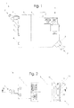
- Fig. 1 shows a device 1 according to the invention for delivering fluid.
- Said device may also be referred to as dispensing head 1.
- Fluid in particular a liquid hot-melt adhesive
- the fluid flows through a heat transfer means 3 which is fixed to a base member 5 with fixing means 4.
- fixing means 4 In the embodiment shown, screw connections are provided as fixing means 4, but other, preferably releasable connections, such as plug connections or the sliding of parts into one another by means of rails, can likewise be considered advantageous.
- heat transfer means 3 the fluid flowing therethrough is brought to a desired, and in particular a selectable reference temperature which is substantially identical to the discharge temperature of the fluid.
- a control unit 6 is likewise fixed to base member 5. Control unit 6 co-operates with a valve mechanism and controls the selectably intermittent or continuous delivery of fluid and application of the fluid to a substrate.
- a nozzle arrangement 7 is also fixed to base member 5. Fluid is received by nozzle arrangement 7 from base member 5 and dispensed through a discharge opening 9.
- Nozzle arrangement 5 also has a mouthpiece holder 10 and a mouthpiece 11, which is fixed to mouthpiece holder 10 with fixing means 8.
- Discharge opening 9 may be wholly or partially embodied in mouthpiece holder 10 or in mouthpiece 11.
- Fig. 2 shows a plan view from below of device 1 in Fig. 1 . It shows inlet opening 2 through which fluid is supplied to device 1, heat transfer means 3, base member 5 and nozzle arrangement 7 mounted on base member 5. Mouthpiece holder 10 is connected to base member 5 by fixing means 13. The discharge opening 9 of nozzle arrangement 7 is configured as a slot nozzle 9'. Mouthpiece 11 extends along the entire length of mouthpiece holder 10. A cross-sectional plane A-A is laid substantially symmetrical through device 1, such that inlet opening 2, heat transfer means 3, base member 5, control unit 6 and nozzle arrangement 7 are shown in cross-section.
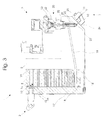
- Fig. 3 shows a cross-section of device 1 through sectional plane A-A.
- the path taken by the fluid until it is delivered to the substrate can readily be seen from the Figure.
- Said heat transfer means 3 has a heat transfer passage 14 which has a plurality of parallel sub-sections defined by two opposite heat transfer surfaces 15, 16.
- heat transfer passage 14 has a meander-shaped configuration which is also shown in Fig. 5 to aid understanding.
- the flow cross-section of the heat transfer passage is not constant. Due to the changing distance between the heat transfer surfaces, the flow cross-section decreases in the direction of flow.
- Heat transfer means 3 is closed on one side by a closure element 17 and on the opposite side abuts base member 5.
- Heat transfer means 3 has apertures 18 on the surfaces which are in contact with closure element 17 and base member 5, said apertures being configured to receive sealing elements or a sealing material.
- Control unit 6 has a valve mechanism 20 which is configured to move a valve piston 21.
- valve piston 21 performs a vertical movement and causes closure or opening of a through opening 23.
- fluid is fed to a discharge passage 25.
- discharge passage 25 which in the chosen embodiment is partially disposed in mouthpiece holder 10 and in mouthpiece 11, fluid is fed to a discharge opening 9 and delivered therethrough onto the substrate.
- Valve mechanism 20 is connected to base member 5 and partially extends into the interior of base member 5. Sealing elements 22 are provided in apertures and prevent the discharge of fluid at those locations.
- the nozzle arrangement likewise has apertures 24 which are configured to receive sealing elements or sealing material.
- Fig. 4 shows an alternative embodiment of a heat transfer means 3, which is connected in appropriate manner to a base member 5 as shown in Fig. 3 , and which also co-operates functionally with the components thereof.
- This embodiment has a plurality of individual plates 26 with apertures 14' that are embodied in a surface of the plates and which form a heat transfer passage - in sandwich construction - in that a through opening 27 extending from the surface of apertures 14' through the thickness of plate 26 is provided in a portion of each plate, thus forming a passage for the fluid from one aperture 14' to the next.
- Heat transfer means 3 is closed on one side by a closure element 17'.
- a second closure element 28 configured to receive a filter arrangement 20' is provided on the opposite side.
- Filter arrangement 20' partially extends into the interior of second closure element 28.
- a filter element 21' extends in the vertical direction in the heat transfer means 3 oriented as shown.
- a through opening 23' through which fluid can pass after filtration is connected to a through passage 19 which is not shown here but corresponds to the one shown in Fig. 3 .
- Plates 26 each have apertures 18' on a contact surface 29 for receiving a sealing element.
- the seco,nd closure element 28 likewise has an aperture 18' for receiving a sealing element.
- Filter arrangement 20' likewise has an aperture 22' for a sealing element.
- Fig. 5 shows a perspective view of an integral embodiment of a heat transfer means 3 as shown in Fig. 3 .
- Flow channel 14 is disposed inside heat transfer means 3 and has a meander-shaped configuration. The flow cross-section decreases in the direction of flow - which runs from top to bottom when the heat transfer means 3 is oriented as shown in Fig. 5 .
- the fluid leaves heat transfer means 3 through an opening 32.
- Aperture 18 for receiving a sealing element is embodied in the form of a circumferential groove.
- Heat transfer means 30 also has through bores 30 through which fixing means 4 (not shown) extend.
- heating elements is shown by way of example in Fig. 6 for an embodiment comprising a plurality of individual plates 26.
- plates 26 and second closure element 28 In a cross-sectional plane parallel to and in the vicinity of the lateral surfaces of the heat transfer means, plates 26 and second closure element 28 have bores 33 configured to receive fixing means.
- Closure element 17' has threaded bores 35 in which screws for fixing plates 26 and closure elements 17', 28 can engage with each other.
- the second closure element 28 and plates 26 also have bores 34 which are configured to receive substantially cylindrical heating elements. Plates 26 are arranged in relation to each other in such a way that bores 33, 34 of the respective plates are coaxial to each other, with the result that the screws and inserted heating elements can extend through the plates.
Landscapes
- Physics & Mathematics (AREA)
- Thermal Sciences (AREA)
- Engineering & Computer Science (AREA)
- Mechanical Engineering (AREA)
- Coating Apparatus (AREA)
- Application Of Or Painting With Fluid Materials (AREA)
- Adhesives Or Adhesive Processes (AREA)
Abstract
Description
- The present invention relates to a device for delivering a fluid, in particular hot-melt adhesive, comprising a base member having an inlet opening for receiving the fluid from a fluid source and an outlet opening for delivering the fluid to a nozzle arrangement, a nozzle arrangement which is associated with the base member and which has a discharge passage with a discharge opening for delivery of the fluid, and a heat transfer means according to the invention for heating or cooling the fluid, having a heat transfer passage through which the fluid can flow. The invention also relates to a corresponding method for delivering a fluid.
- In many industrial applications, free-flowing materials (fluids) are delivered with the aid of fluid delivery devices and placed or dispensed onto substrates. The fluids may be adhesives, paints, sealing materials or gases, for example, and the substrates may be sanitary articles, plastic films, furniture or machine parts and the like. Depending on the specific application, the fluids may be delivered in the form of beads, strips or films, for example, or the material may be sprayed, if necessary, with the aid of a gaseous stream that influences the fluid. The fluid delivery devices are connected to a fluid source, for example a container for adhesives, and the fluid is transported with the aid of a pump to a discharge opening that is circular or slot-shaped, for example.
- In some applications, it is advantageous or necessary that the fluid be heated before it is delivered. In the case of spraying methods, it may be advantageous to heat a gas that affects a liquid to be delivered. In many applications, it may be necessary to heat a liquid to be delivered, in particular a fluid hot-melt adhesive prior to delivery and application to a substrate or material. A fluid delivery device with an integrated heat transfer chamber is known from the applicant's patent
EP 1 419 826 A2 , for example, in which it was proposed that a structure with cavities, made in particular of a sintering material, be disposed in a heat transfer chamber in order to influence the transfer of heat in advantageous manner. - There is a need for further improvement of fluid delivery devices which have a heat transfer means. There is therefore a need to optimize the fluid mechanics of heat transfer means for heating or also for cooling a fluid, so that they can be better adapted to changing viscosities of the fluid, for example. There is also a need to reduce the geometrical dimensions of the fluid delivery device as a whole. In many cases, it is also necessary to process and apply temperature-sensitive fluids, particularly hot-melt adhesives or thermoplastic materials which must be gently heated, without causing temporary local overheating and hence detrimental impacts on the properties of the material.
- The object of the present invention is to specify a device and a method for delivering a fluid, and a heat transfer means for a fluid delivery device, which take up relatively little installation space and/or which are suitable for processing temperature-sensitive fluids, particularly hot-melt adhesives, and/or are fluidically optimized, especially with regard to changing viscosities of the fluids.
- The invention achieves this object, according to a first aspect of the invention, with a device of the kind specified at the outset, in which the heat transfer passage is of a flow cross-section which changes in the flow direction.
- The heat transfer means is fluidically optimized due to the flow cross-section of the heat transfer passage changing in the flow direction of the fluid. Depending on the respective fluid temperature, the viscosity of the fluid changes during heating or cooling. As a result of such change, there is also a change in the flow resistances, flow speeds and shearing forces within the fluid. By virtue of the inventive heat transfer passage having a flow cross-section that changes and is adapted to the respective application conditions, the flow speed and/or shearing forces or other parameters can be adapted or positively affected, depending on the specific application, so that the fluid is gently heated or cooled.
- In one particularly preferred embodiment in which, for example, hot-melt adhesive or other fluid or gases are to be delivered, it is proposed that the heat transfer passage has a flow cross-section which decreases, at least in sections thereof, in the direction of fluid flow. In this way, consideration is given to the fact that the viscosity usually decreases with increasing fluid temperature. Flow cross-sections which decrease in this manner result in a substantially uniform flow resistance and possibly also in uniform flow speed and shearing forces in the fluid.
- Another preferred embodiment of the invention is characterized in that the heat transfer passage is defined by heat transfer surfaces which are arranged in substantially mutually parallel relationship, and the mutual spacing of which decreases in the direction of the intended preferred flow of material. A decreasing flow cross-section is therefore realized with this relatively simple design measure.
- According to another aspect of the invention, the object is achieved, and the invention is advantageously developed, by a device of the kind specified at the outset in which the heat transfer passage is of a substantially meander-shaped configuration, at least portion-wise.
- By means of such a meander-shaped configuration, the design and production of a fluid delivery device can be made especially compact.
- In one advantageous development of the invention, it is proposed that the heat transfer means comprise a base member through which the heat transfer passage defined by the heat transfer surfaces extends along a curved path disposed between two closure elements, and that the base member is configured at at least one closure element to receive a heating or cooling element. The fluid thus flows in a meandering manner along a curved path, thus achieving efficient heat transfer within a small installation space. It is advantageous when at least one closure element of the base member, or the base member itself, is adapted to receive a sealing element.
- According to a further aspect, the invention achieves its object in a device of the kind specified at the outset, and/or is advantageously developed, in that the heat transfer means has a plurality of plates which each have at least one respective contact face and are so arranged that the contact faces of two adjacent plates are respectively connected to each other, wherein a continuous heat transfer passage extends through the entirety of the plates in their connected state, and the plates have apertures, in particular through openings, for receiving heating elements.
- Due to the plurality of plates, the heat transfer means has a sandwich construction which provides advantages in production engineering, especially. If so required, the size and thermal capacity of the heat transfer means can be adapted in a simple manner by selecting the appropriate number of plates.
- According to one development of the invention in respect of a preferred meander-shaped configuration of the flow passage, it is proposed that, on at least one face, the plates have an aperture which does not extend completely through the thickness of a plate, and that the apertures have at least one through opening in an end portion of an aperture, which through opening is adapted for the through flow of fluid from one aperture into the aperture in an adjacent plate, so that the entire heat transfer passage is embodied by coupling the apertures. It is advantageous when the plates are adapted at at least one contact face to receive a sealing element. The outer plates of an assembly of plates can preferably be closed by means of closure elements.
- According to one other aspect of the invention, the object of a device of the kind specified at the outset is achieved, and the invention developed, in that the heat transfer surfaces of the heat transfer means are configured so that a reference output temperature of the fluid can be set, and that the heat transfer surfaces of the heat transfer means are designed with a surface area of such magnitude as to permit the attainment of the reference temperature by a heating temperature of the heat transfer surfaces, which is substantially equal to the reference temperature of the fluid.
- The invention likewise achieves its object, according to this aspect, with a method of the kind initially specified, in that the reference temperature of the fluid is reached when the fluid flows over the heat transfer surfaces of the heat transfer means, and in that a heating temperature which is substantially equal to the reference temperature of the fluid obtains at heat transfer surfaces.
- By dimensioning the heat transfer passage in the manner of the invention such that, when the fluid is flowing through or has finishing flowing through the heat transfer means, the actual or reference temperature of the fluid is substantially equal to the heating temperature of the heat transfer surfaces i.e. the fluid has reached their surface temperature; particularly gentle heating (or cooling) of the fluid can thus be achieved, which is advantageous in the case of temperature-sensitive fluids, and particularly of thermoplastic adhesives, and any (local) damage due to overheating is prevented. In other words, by dimensioning the passage in the manner of the invention, the selected surface temperature is so low that overheating or excessive temperature gradients in the fluid are effectively prevented.
- According to one preferred embodiment of the invention, it is proposed that the heat transfer means is essentially produced from a strongly heat-conducting material, in particular copper or aluminum. It is particularly advantageous for the production process when the heat transfer passage is produced by wire erosion.
- Finally, the invention proposes a heat transfer means having the features as specified in the claims. Advantageous developments are specified in the subclaims.
- The invention shall now be described on the basis of embodiments and with reference to the Figures, in which
- Fig. 1
- shows a side elevation view of a dispensing head according to the invention,
- Fig. 2
- shows a view from below of the dispensing head in
Fig. 1 , - Fig. 3
- shows a cross-section of a side elevation view of the dispenser head in
Fig. 1 and 2 , in the sectional plane A-A as shown inFig. 2 , - Fig. 4
- shows a cross-sectional view of another embodiment of a heat transfer means;
- Fig. 5
- shows a perspective view of an embodiment of a heat transfer means, and
- Fig. 6
- shows a cross-sectional view of an embodiment of a heat transfer means with apertures for heating elements.
-
Fig. 1 shows a device 1 according to the invention for delivering fluid. Said device may also be referred to as dispensing head 1. Fluid, in particular a liquid hot-melt adhesive, is supplied to device 1 through aninlet opening 2. The fluid flows through a heat transfer means 3 which is fixed to abase member 5 withfixing means 4. In the embodiment shown, screw connections are provided as fixing means 4, but other, preferably releasable connections, such as plug connections or the sliding of parts into one another by means of rails, can likewise be considered advantageous. In heat transfer means 3, the fluid flowing therethrough is brought to a desired, and in particular a selectable reference temperature which is substantially identical to the discharge temperature of the fluid. A control unit 6 is likewise fixed tobase member 5. Control unit 6 co-operates with a valve mechanism and controls the selectably intermittent or continuous delivery of fluid and application of the fluid to a substrate. - A
nozzle arrangement 7 is also fixed tobase member 5. Fluid is received bynozzle arrangement 7 frombase member 5 and dispensed through adischarge opening 9.Nozzle arrangement 5 also has amouthpiece holder 10 and amouthpiece 11, which is fixed tomouthpiece holder 10 with fixing means 8.Discharge opening 9 may be wholly or partially embodied inmouthpiece holder 10 or inmouthpiece 11. -
Fig. 2 shows a plan view from below of device 1 inFig. 1 . It shows inlet opening 2 through which fluid is supplied to device 1, heat transfer means 3,base member 5 andnozzle arrangement 7 mounted onbase member 5.Mouthpiece holder 10 is connected tobase member 5 by fixingmeans 13. Thedischarge opening 9 ofnozzle arrangement 7 is configured as a slot nozzle 9'.Mouthpiece 11 extends along the entire length ofmouthpiece holder 10. A cross-sectional plane A-A is laid substantially symmetrical through device 1, such thatinlet opening 2, heat transfer means 3,base member 5, control unit 6 andnozzle arrangement 7 are shown in cross-section. -
Fig. 3 shows a cross-section of device 1 through sectional plane A-A. The path taken by the fluid until it is delivered to the substrate can readily be seen from the Figure. After entering throughinlet opening 2, the fluid is fed to heat transfer means 3. Said heat transfer means 3 has aheat transfer passage 14 which has a plurality of parallel sub-sections defined by two opposite heat transfer surfaces 15, 16. In the embodiment shown,heat transfer passage 14 has a meander-shaped configuration which is also shown inFig. 5 to aid understanding. The flow cross-section of the heat transfer passage is not constant. Due to the changing distance between the heat transfer surfaces, the flow cross-section decreases in the direction of flow. - Heat transfer means 3 is closed on one side by a
closure element 17 and on the opposite side abutsbase member 5. Heat transfer means 3 hasapertures 18 on the surfaces which are in contact withclosure element 17 andbase member 5, said apertures being configured to receive sealing elements or a sealing material. - The fluid is fed from
heat transfer passage 14 to a through-channel 19 inbase member 5, and passes through said channel to control unit 6. Control unit 6 has avalve mechanism 20 which is configured to move avalve piston 21. In the selected orientation of device 1,valve piston 21 performs a vertical movement and causes closure or opening of a throughopening 23. Whenvalve piston 21 is in the open position, fluid is fed to adischarge passage 25. Throughdischarge passage 25, which in the chosen embodiment is partially disposed inmouthpiece holder 10 and inmouthpiece 11, fluid is fed to adischarge opening 9 and delivered therethrough onto the substrate. -
Valve mechanism 20 is connected tobase member 5 and partially extends into the interior ofbase member 5.Sealing elements 22 are provided in apertures and prevent the discharge of fluid at those locations. The nozzle arrangement likewise hasapertures 24 which are configured to receive sealing elements or sealing material. -
Fig. 4 shows an alternative embodiment of a heat transfer means 3, which is connected in appropriate manner to abase member 5 as shown inFig. 3 , and which also co-operates functionally with the components thereof. This embodiment has a plurality ofindividual plates 26 with apertures 14' that are embodied in a surface of the plates and which form a heat transfer passage - in sandwich construction - in that a throughopening 27 extending from the surface of apertures 14' through the thickness ofplate 26 is provided in a portion of each plate, thus forming a passage for the fluid from one aperture 14' to the next. Heat transfer means 3 is closed on one side by a closure element 17'. In the chosen embodiment, a second closure element 28 configured to receive a filter arrangement 20' is provided on the opposite side. Filter arrangement 20' partially extends into the interior of second closure element 28. A filter element 21' extends in the vertical direction in the heat transfer means 3 oriented as shown. A through opening 23' through which fluid can pass after filtration is connected to a throughpassage 19 which is not shown here but corresponds to the one shown inFig. 3 . -
Plates 26 each have apertures 18' on acontact surface 29 for receiving a sealing element. The seco,nd closure element 28 likewise has an aperture 18' for receiving a sealing element. Filter arrangement 20' likewise has an aperture 22' for a sealing element. -
Fig. 5 shows a perspective view of an integral embodiment of a heat transfer means 3 as shown inFig. 3 .Flow channel 14 is disposed inside heat transfer means 3 and has a meander-shaped configuration. The flow cross-section decreases in the direction of flow - which runs from top to bottom when the heat transfer means 3 is oriented as shown inFig. 5 . The fluid leaves heat transfer means 3 through anopening 32.Aperture 18 for receiving a sealing element is embodied in the form of a circumferential groove. Heat transfer means 30 also has throughbores 30 through which fixing means 4 (not shown) extend. - The arrangement of heating elements is shown by way of example in
Fig. 6 for an embodiment comprising a plurality ofindividual plates 26. In a cross-sectional plane parallel to and in the vicinity of the lateral surfaces of the heat transfer means,plates 26 and second closure element 28 havebores 33 configured to receive fixing means. Closure element 17' has threadedbores 35 in which screws for fixingplates 26 and closure elements 17', 28 can engage with each other. The second closure element 28 andplates 26 also havebores 34 which are configured to receive substantially cylindrical heating elements.Plates 26 are arranged in relation to each other in such a way that bores 33, 34 of the respective plates are coaxial to each other, with the result that the screws and inserted heating elements can extend through the plates.
Claims (16)
- A device for delivering a fluid, in particular hot-melt adhesive, comprising a base member having an inlet opening for receiving the fluid from a fluid source and an outlet opening for delivering the fluid to a nozzle arrangement,
a nozzle arrangement which is associated with the base member and which has a discharge passage with a discharge opening for delivery of the fluid, and a heat transfer means for heating or cooling the fluid, having a heat transfer passage through which fluid can flow,
characterized in that the heat transfer passage is of a flow cross-section which changes in the direction of flow. - A device as set forth in claim 1,
characterized in that the heat transfer passage at least portion-wise is of a flow cross-section which decreases in the flow direction. - A device as set forth in claim 1 or claim 2,
characterized in that the heat transfer passage is defined by heat transfer surfaces which are arranged in substantially mutually parallel relationship and the mutual spacing of which decreases in the direction of the intended preferred flow of material. - A device as set forth in the preamble of claim 1 or in one of the preceding claims,
characterized in that the heat transfer passage is at least portion-wise of a substantially meander-shaped configuration. - A device as set forth in claim 4,
characterized in that the heat transfer means has a base member through which the heat transfer passage which is defined by the heat transfer surfaces extends along a curved path disposed between two closure elements, and
the base member is designed at at least one closure element to receive a heating element or cooling element. - A device as set forth in claim 5,
characterized in that at least one closure element of the base member, or the base member itself, is adapted to receive a sealing element. - A device as set forth in the preamble of claim 1 or in one of the preceding claims,
characterized in that the heat transfer means has a plurality of plates which each have at least one respective contact face and are so arranged that the contact faces of two adjacent plates are respectively connected to each other, wherein a continuous heat transfer passage extends through the entirety of the plates in their connected state, and the plates have apertures, in particular through openings, for receiving heating elements. - A device as set forth in claim 7,
characterized in that on at least one face the plates have an aperture which does not extend completely through the thickness of a plate and the apertures have at least one through opening in an end portion of an aperture, said through opening being adapted for the through flow of fluid from one aperture into the aperture in an adjacent plate, so that the entire heat transfer passage is embodied by coupling the apertures. - A device as set forth in claim 7 or claim 8,
characterized in that at at least one contact face the plates are adapted to receive a sealing element. - A device as set forth in one of claims 7 through 9,
characterized in that the outer plates of an assembly of plates can be closed with closure elements. - A device as set forth in the preamble of claim 1 or in one of the preceding claims,
characterized in that the heat transfer means is adapted to set a reference outlet temperature for the fluid, and
the heat transfer surfaces of the heat transfer means are of a surface area of such a magnitude as to permit the attainment of the reference temperature by a heating temperature of the heat transfer surfaces which is substantially equal to the reference temperature of the fluid. - A device as set forth in one of the preceding claims,
characterized in that the heat transfer means is produced substantially from a heat-conducting material, in particular copper or aluminum. - A device as set forth in one of the preceding claims,
characterized in that the heat transfer passage is produced by wire erosion. - A method of delivering a fluid,
wherein fluid from a fluid source is fed to a device for delivering a fluid, in particular a hot-melt adhesive, through an inlet opening, and the fluid then flows through a heat transfer means, as a result of which a reference temperature is produced in the fluid,
and the fluid is then fed from the heat transfer means through a discharge passage to a discharge opening of a nozzle arrangement for delivery of the fluid,
characterized in that the reference temperature of the fluid is reached when flowing over the heat transfer surfaces of the heat transfer means, and
a heating temperature which is substantially equal to the reference temperature of the fluid obtains at heat transfer surfaces. - A method as set forth in claim 14,
characterized in that the fluid to be delivered is an adhesive, in particular a hot-melt adhesive. - A heat transfer device for heating or cooling a fluid, in particular hot-melt adhesive, suitable in particular for use in a device as set forth in claim 1 or claim 4 and having the characterizing features of one or more of claims 1 through 13.
Applications Claiming Priority (1)
| Application Number | Priority Date | Filing Date | Title |
|---|---|---|---|
| DE102007048046A DE102007048046A1 (en) | 2007-10-05 | 2007-10-05 | Apparatus and method for dispensing a fluid, in particular hot-melt adhesive |
Publications (3)
| Publication Number | Publication Date |
|---|---|
| EP2045020A2 true EP2045020A2 (en) | 2009-04-08 |
| EP2045020A3 EP2045020A3 (en) | 2013-08-28 |
| EP2045020B1 EP2045020B1 (en) | 2020-02-19 |
Family
ID=40262251
Family Applications (1)
| Application Number | Title | Priority Date | Filing Date |
|---|---|---|---|
| EP08165725.6A Not-in-force EP2045020B1 (en) | 2007-10-05 | 2008-10-02 | Device and method for delivering a fluid, in particular hot-melt adhesive |
Country Status (6)
| Country | Link |
|---|---|
| US (1) | US8348100B2 (en) |
| EP (1) | EP2045020B1 (en) |
| JP (1) | JP2009160571A (en) |
| CN (1) | CN101402081B (en) |
| DE (1) | DE102007048046A1 (en) |
| ES (1) | ES2787227T3 (en) |
Cited By (1)
| Publication number | Priority date | Publication date | Assignee | Title |
|---|---|---|---|---|
| JP2017532394A (en) * | 2014-08-17 | 2017-11-02 | フォーマティック, エルエルシー | Self-foaming hot melt adhesive composition and method for making and using the same |
Families Citing this family (8)
| Publication number | Priority date | Publication date | Assignee | Title |
|---|---|---|---|---|
| US20130112710A1 (en) * | 2011-11-07 | 2013-05-09 | Graco Minnesota Inc. | Cooling system and method |
| US9615405B2 (en) * | 2013-09-16 | 2017-04-04 | Nordson Corporation | Heat exchange devices, liquid adhesive systems, and related methods |
| DE102014001897A1 (en) | 2014-02-14 | 2015-08-20 | Focke & Co. (Gmbh & Co. Kg) | Valve arrangement for applying flowable media to surfaces |
| US10279361B2 (en) | 2014-08-17 | 2019-05-07 | Foammatick, Llc | Self-foaming hot melt adhesive compositions and methods of making and using same |
| CN105562296A (en) * | 2014-11-05 | 2016-05-11 | 诺信公司 | System and method for filling a hot melt adhesive tank |
| MX395393B (en) * | 2015-03-16 | 2025-03-25 | Nordson Corp | HEAT EXCHANGE DEVICE WITH THIN RING-SHAPED SLIT SECTION FOR USE IN LIQUID ADHESIVE SYSTEMS AND RELATED METHODS. |
| JP6878731B2 (en) * | 2019-06-20 | 2021-06-02 | アイイーシー ファブリケーション | Methods and equipment for discharging temperature-controlled automotive body sealants |
| EP4032620B1 (en) * | 2021-01-22 | 2023-08-09 | Robatech AG | Melting apparatus for providing a molten medium |
Citations (1)
| Publication number | Priority date | Publication date | Assignee | Title |
|---|---|---|---|---|
| EP1419826A2 (en) | 2002-11-15 | 2004-05-19 | Nordson Corporation | Method, device and cartridge for dispensing a fluid |
Family Cites Families (15)
| Publication number | Priority date | Publication date | Assignee | Title |
|---|---|---|---|---|
| US2060440A (en) * | 1935-03-28 | 1936-11-10 | Rosenblad Curt Fredrik | Heat exchange apparatus |
| GB1469656A (en) * | 1974-03-14 | 1977-04-06 | Ciba Geigy Ag | Heat exchangers |
| US4679710A (en) * | 1981-06-22 | 1987-07-14 | Nordson Corporation | Hot melt foam adhesive system |
| US4485942A (en) * | 1981-09-14 | 1984-12-04 | Nordson Corporation | Apparatus for melting and dispensing thermoplastic material |
| US4667852A (en) * | 1983-09-29 | 1987-05-26 | Bernd Siemann | Apparatus for preparing and dispensing thermoplastic resin |
| JPS6191368U (en) * | 1984-11-21 | 1986-06-13 | ||
| DE3514053A1 (en) * | 1985-04-18 | 1986-10-23 | Lacrex Brevetti S.A., Orselina | DEVICE FOR PREHEATING LIQUIDS, ESPECIALLY LIQUID FUEL OR FUEL |
| US4782212A (en) * | 1986-11-17 | 1988-11-01 | Bakke Allan P | Electric blood warmer utilizing a metallic ribbon-flow cartridge |
| US5133483A (en) * | 1990-08-23 | 1992-07-28 | Viking Industries | Metering system |
| US5353868A (en) * | 1993-04-19 | 1994-10-11 | Abbott Roy W | Integral tube and strip fin heat exchanger circuit |
| CN2221198Y (en) * | 1994-09-13 | 1996-02-28 | 刘崇华 | Spiral plate heat exchanger |
| JP4608763B2 (en) * | 2000-11-09 | 2011-01-12 | 日本電気株式会社 | Semiconductor device |
| US6669057B2 (en) * | 2001-10-31 | 2003-12-30 | Nordson Corporation | High-speed liquid dispensing modules |
| US6938688B2 (en) * | 2001-12-05 | 2005-09-06 | Thomas & Betts International, Inc. | Compact high efficiency clam shell heat exchanger |
| US20060097010A1 (en) * | 2004-10-28 | 2006-05-11 | Nordson Corporation | Device for dispensing a heated liquid |
-
2007
- 2007-10-05 DE DE102007048046A patent/DE102007048046A1/en not_active Withdrawn
-
2008
- 2008-10-01 US US12/243,395 patent/US8348100B2/en not_active Expired - Fee Related
- 2008-10-02 ES ES08165725T patent/ES2787227T3/en active Active
- 2008-10-02 EP EP08165725.6A patent/EP2045020B1/en not_active Not-in-force
- 2008-10-03 JP JP2008258095A patent/JP2009160571A/en active Pending
- 2008-10-06 CN CN200810168982.XA patent/CN101402081B/en not_active Expired - Fee Related
Patent Citations (1)
| Publication number | Priority date | Publication date | Assignee | Title |
|---|---|---|---|---|
| EP1419826A2 (en) | 2002-11-15 | 2004-05-19 | Nordson Corporation | Method, device and cartridge for dispensing a fluid |
Cited By (2)
| Publication number | Priority date | Publication date | Assignee | Title |
|---|---|---|---|---|
| JP2017532394A (en) * | 2014-08-17 | 2017-11-02 | フォーマティック, エルエルシー | Self-foaming hot melt adhesive composition and method for making and using the same |
| JP2020041155A (en) * | 2014-08-17 | 2020-03-19 | フォーマティック, エルエルシー | Self-foaming hot melt adhesive compositions and methods of making and using the same |
Also Published As
| Publication number | Publication date |
|---|---|
| CN101402081B (en) | 2014-10-29 |
| EP2045020A3 (en) | 2013-08-28 |
| JP2009160571A (en) | 2009-07-23 |
| US8348100B2 (en) | 2013-01-08 |
| ES2787227T3 (en) | 2020-10-15 |
| DE102007048046A1 (en) | 2009-04-09 |
| US20090098287A1 (en) | 2009-04-16 |
| CN101402081A (en) | 2009-04-08 |
| EP2045020B1 (en) | 2020-02-19 |
Similar Documents
| Publication | Publication Date | Title |
|---|---|---|
| EP2045020B1 (en) | Device and method for delivering a fluid, in particular hot-melt adhesive | |
| US8453880B2 (en) | Process air-assisted dispensing systems and methods | |
| ES3035649T3 (en) | Liquid material dispensing system having a sleeve heater | |
| US7861666B2 (en) | Width adjustable multi slot gun | |
| CN104661759B (en) | Apparatus for coating and coating method | |
| CN103168351B (en) | Method and apparatus for fabricating metal contact structures for electrically connecting photovoltaic solar cells | |
| JPH06227651A (en) | Device for classifying and passing over material which can flow | |
| EP2857111B1 (en) | Heat exchange devices, liquid adhesive systems, and related methods | |
| JP2002180321A5 (en) | ||
| CN1108880C (en) | Hot-melt binder spraying system fitted with laminated thin-sheet air heater | |
| JP6794367B2 (en) | Heat exchangers with narrow ring-shaped slit compartments and related methods used in liquid adhesive systems. | |
| JP2008161865A (en) | Device having slotted nozzle assembly for dispensing fluid | |
| TW201801801A (en) | Applicator and application device | |
| JP2011092934A (en) | Apparatus for guiding substrate and apparatus for dispensing fluid | |
| CN104093496B (en) | Foam heat exchangers for hot melt adhesive or other thermoplastic dispensing applicators | |
| EP1902787B1 (en) | Apparatus for applying fluids such as adhesive, in particular hot melt adhesive | |
| JP5693045B2 (en) | Valve device with integrated mixer element | |
| JP3989931B2 (en) | Electrostatic coating device for food | |
| CN110494268A (en) | Fluid channel, method of making fluid channel, and container handling system |
Legal Events
| Date | Code | Title | Description |
|---|---|---|---|
| PUAI | Public reference made under article 153(3) epc to a published international application that has entered the european phase |
Free format text: ORIGINAL CODE: 0009012 |
|
| AK | Designated contracting states |
Kind code of ref document: A2 Designated state(s): AT BE BG CH CY CZ DE DK EE ES FI FR GB GR HR HU IE IS IT LI LT LU LV MC MT NL NO PL PT RO SE SI SK TR |
|
| AX | Request for extension of the european patent |
Extension state: AL BA MK RS |
|
| RIC1 | Information provided on ipc code assigned before grant |
Ipc: B05C 11/10 20060101ALI20130327BHEP Ipc: B05C 5/00 20060101AFI20130327BHEP Ipc: B29B 13/02 20060101ALN20130327BHEP |
|
| PUAL | Search report despatched |
Free format text: ORIGINAL CODE: 0009013 |
|
| AK | Designated contracting states |
Kind code of ref document: A3 Designated state(s): AT BE BG CH CY CZ DE DK EE ES FI FR GB GR HR HU IE IS IT LI LT LU LV MC MT NL NO PL PT RO SE SI SK TR |
|
| AX | Request for extension of the european patent |
Extension state: AL BA MK RS |
|
| RIC1 | Information provided on ipc code assigned before grant |
Ipc: B05C 5/00 20060101AFI20130725BHEP Ipc: B29B 13/02 20060101ALN20130725BHEP Ipc: B05C 11/10 20060101ALI20130725BHEP |
|
| 17P | Request for examination filed |
Effective date: 20140228 |
|
| RBV | Designated contracting states (corrected) |
Designated state(s): AT BE BG CH CY CZ DE DK EE ES FI FR GB GR HR HU IE IS IT LI LT LU LV MC MT NL NO PL PT RO SE SI SK TR |
|
| AKX | Designation fees paid |
Designated state(s): DE ES IT |
|
| 17Q | First examination report despatched |
Effective date: 20151119 |
|
| GRAP | Despatch of communication of intention to grant a patent |
Free format text: ORIGINAL CODE: EPIDOSNIGR1 |
|
| RIC1 | Information provided on ipc code assigned before grant |
Ipc: B29B 13/02 20060101ALN20190918BHEP Ipc: B05C 11/10 20060101ALI20190918BHEP Ipc: B05C 5/00 20060101AFI20190918BHEP |
|
| INTG | Intention to grant announced |
Effective date: 20191001 |
|
| GRAS | Grant fee paid |
Free format text: ORIGINAL CODE: EPIDOSNIGR3 |
|
| GRAA | (expected) grant |
Free format text: ORIGINAL CODE: 0009210 |
|
| AK | Designated contracting states |
Kind code of ref document: B1 Designated state(s): DE ES IT |
|
| REG | Reference to a national code |
Ref country code: DE Ref legal event code: R096 Ref document number: 602008062150 Country of ref document: DE |
|
| REG | Reference to a national code |
Ref country code: ES Ref legal event code: FG2A Ref document number: 2787227 Country of ref document: ES Kind code of ref document: T3 Effective date: 20201015 |
|
| REG | Reference to a national code |
Ref country code: DE Ref legal event code: R097 Ref document number: 602008062150 Country of ref document: DE |
|
| PLBE | No opposition filed within time limit |
Free format text: ORIGINAL CODE: 0009261 |
|
| STAA | Information on the status of an ep patent application or granted ep patent |
Free format text: STATUS: NO OPPOSITION FILED WITHIN TIME LIMIT |
|
| 26N | No opposition filed |
Effective date: 20201120 |
|
| PGFP | Annual fee paid to national office [announced via postgrant information from national office to epo] |
Ref country code: DE Payment date: 20201022 Year of fee payment: 13 Ref country code: IT Payment date: 20201026 Year of fee payment: 13 Ref country code: ES Payment date: 20201224 Year of fee payment: 13 |
|
| REG | Reference to a national code |
Ref country code: DE Ref legal event code: R119 Ref document number: 602008062150 Country of ref document: DE |
|
| PG25 | Lapsed in a contracting state [announced via postgrant information from national office to epo] |
Ref country code: DE Free format text: LAPSE BECAUSE OF NON-PAYMENT OF DUE FEES Effective date: 20220503 |
|
| PG25 | Lapsed in a contracting state [announced via postgrant information from national office to epo] |
Ref country code: IT Free format text: LAPSE BECAUSE OF NON-PAYMENT OF DUE FEES Effective date: 20211002 |
|
| REG | Reference to a national code |
Ref country code: ES Ref legal event code: FD2A Effective date: 20230203 |
|
| PG25 | Lapsed in a contracting state [announced via postgrant information from national office to epo] |
Ref country code: ES Free format text: LAPSE BECAUSE OF NON-PAYMENT OF DUE FEES Effective date: 20211003 |