EP1419826A2 - Method, device and cartridge for dispensing a fluid - Google Patents
Method, device and cartridge for dispensing a fluid Download PDFInfo
- Publication number
- EP1419826A2 EP1419826A2 EP03025921A EP03025921A EP1419826A2 EP 1419826 A2 EP1419826 A2 EP 1419826A2 EP 03025921 A EP03025921 A EP 03025921A EP 03025921 A EP03025921 A EP 03025921A EP 1419826 A2 EP1419826 A2 EP 1419826A2
- Authority
- EP
- European Patent Office
- Prior art keywords
- fluid
- heat transfer
- permeable structure
- transfer chamber
- dispensing
- Prior art date
- Legal status (The legal status is an assumption and is not a legal conclusion. Google has not performed a legal analysis and makes no representation as to the accuracy of the status listed.)
- Withdrawn
Links
Images


Classifications
-
- H—ELECTRICITY
- H05—ELECTRIC TECHNIQUES NOT OTHERWISE PROVIDED FOR
- H05B—ELECTRIC HEATING; ELECTRIC LIGHT SOURCES NOT OTHERWISE PROVIDED FOR; CIRCUIT ARRANGEMENTS FOR ELECTRIC LIGHT SOURCES, IN GENERAL
- H05B3/00—Ohmic-resistance heating
- H05B3/40—Heating elements having the shape of rods or tubes
- H05B3/42—Heating elements having the shape of rods or tubes non-flexible
-
- B—PERFORMING OPERATIONS; TRANSPORTING
- B05—SPRAYING OR ATOMISING IN GENERAL; APPLYING FLUENT MATERIALS TO SURFACES, IN GENERAL
- B05C—APPARATUS FOR APPLYING FLUENT MATERIALS TO SURFACES, IN GENERAL
- B05C5/00—Apparatus in which liquid or other fluent material is projected, poured or allowed to flow on to the surface of the work
- B05C5/001—Apparatus in which liquid or other fluent material is projected, poured or allowed to flow on to the surface of the work incorporating means for heating or cooling the liquid or other fluent material
-
- B—PERFORMING OPERATIONS; TRANSPORTING
- B05—SPRAYING OR ATOMISING IN GENERAL; APPLYING FLUENT MATERIALS TO SURFACES, IN GENERAL
- B05C—APPARATUS FOR APPLYING FLUENT MATERIALS TO SURFACES, IN GENERAL
- B05C5/00—Apparatus in which liquid or other fluent material is projected, poured or allowed to flow on to the surface of the work
- B05C5/02—Apparatus in which liquid or other fluent material is projected, poured or allowed to flow on to the surface of the work the liquid or other fluent material being discharged through an outlet orifice by pressure, e.g. from an outlet device in contact or almost in contact, with the work
- B05C5/027—Coating heads with several outlets, e.g. aligned transversally to the moving direction of a web to be coated
-
- H—ELECTRICITY
- H05—ELECTRIC TECHNIQUES NOT OTHERWISE PROVIDED FOR
- H05B—ELECTRIC HEATING; ELECTRIC LIGHT SOURCES NOT OTHERWISE PROVIDED FOR; CIRCUIT ARRANGEMENTS FOR ELECTRIC LIGHT SOURCES, IN GENERAL
- H05B2203/00—Aspects relating to Ohmic resistive heating covered by group H05B3/00
- H05B2203/021—Heaters specially adapted for heating liquids
Definitions
- the invention relates to a method for dispensing a fluid, in which the fluid from a fluid source of a device for dispensing the Fluids supplied and through one assigned to the dispensing device Exit opening is released.
- the invention relates to a device for dispensing fluid, with a connectable to a fluid source and into a dispensing opening for dispensing the fluid flow channel.
- Flowable materials are used in many industrial applications (Fluids) dispensed and applied using fluid dispensers Deposited or applied substrates.
- the flowable materials can be, for example, adhesives, varnishes, sealing materials and for the substrates around hygiene articles, plastic films, furniture or Act machine parts or the like.
- the delivery of the flowable Depending on the application, materials can, for example, be strip or foil-shaped, or the material is optionally sprayed with the help of a gas jet influencing the fluid.
- the fluid dispensers are to a fluid source, for example an adhesive container is connected and the fluid is removed using a Pump with the interposition of so-called order valves for example a circular or slot-shaped outlet opening promoted.
- the fluid before Levy is heated.
- a to heat gas acting on the fluid to be dispensed a base body of the dispenser to be electrically heated, so that formed in the base body Liquid flowing through flow channels or gas flowing therethrough is heated by the Flow channel limiting inner wall to a Heat transfer comes through convection.
- a gas in a fluid dispenser it is known to be a zigzag training flow channel for the gas.
- the zigzag Design serves the purpose that for a Heat transfer available flow path too extend and thereby improve the heat transfer.
- the disadvantage of this is that the design effort for one Production of such a flow course is very complex and is therefore expensive.
- the object of the present invention is a method and a Specify the device of the type mentioned and a cartridge, with which the heat transfer is improved.
- the invention solves the problem with an input method mentioned type in that the fluid prior to delivery by the Outlet opening for heating or cooling by a Heat transfer chamber flows in which a fluid-permeable, structure having a plurality of communicating cavities is formed, which is flowed around by the fluid.
- the invention also achieves the object in an input device mentioned type by a heat transfer chamber for heating or cooling the fluid in which a fluid permeable, a Large number of communicating cavities structure is trained.
- the advantages of the method and the Device according to the invention consist in that the Heat transfer for heating or alternatively for cooling a liquid and / or a gas prior to delivery from the Dispensing device can be significantly improved by the Provision of the fluid-permeable structure according to the invention, the is flowed around by the fluid.
- the fluid permeable structure is preferably a sintered material, particularly preferably a Sintered metal, which is essentially rigid and a variety of interconnected cavities through which the fluid can flow through.
- the heat transfer is due to the fluid permeable, in the flow channel of the heat transfer chamber lying structure improved that the for Relevant surface heat transfer between the structure and the fluid to be heated and possibly also cooled is significantly enlarged, reproduced.
- the structure is closer to below described way heated so that heat is given off to the fluid can be over the large surface of the structure. Furthermore the heat transfer is improved in that the fluid during the flow through the structure is deflected in many ways and thereby a certain amount of turbulence arises, which improves the Ensures heat transfer.
- Heat transfer such as heating a liquid or a Gases improved significantly and the device can be relative be built compact. Especially when heating Pressurized gas for dispensing devices for spraying liquids they are like hot melt adhesive due to the fluid permeability Structure enlarged compared to a free flow channel Flow resistances negligible.
- the preferred sintered metal has the advantage that it is a large inner Has heat transfer surface, is dimensionally stable, easy manufacture and process and thus to the respective applications can be adjusted.
- others can also be used according to the invention open-pore, preferably essentially rigid structures such as Fabrics, metal mesh or rigid, open-cell foams be used.
- the fluid can advantageously flow through the Heat transfer chamber heated or cooled and at the same time be filtered through the fluid permeable structure, so that in addition for heating a cleaning of a gas or a liquid is made.
- the fluid-permeable structure is preferably in contact with the fluid inner surface of the heat transfer chamber. This takes one efficient heat transfer instead.
- the fluid is a liquid, is in particular a flowable plastic such as hot melt adhesive and by flowing through the heat transfer chamber is heated. It is equally preferred that the fluid is a gas, is preferably air and by flowing through it Heat transfer chamber is heated, resulting in spray applications is advantageous.
- the device according to the invention is thereby constructive simply trained that the heat transfer chamber is formed by a section of the flow channel in which the fluid permeable structure is used.
- the heat transfer chamber is formed by a section of the flow channel in which the fluid permeable structure is used.
- the fluid-permeable structure in the is essentially designed as a cylindrical body which in a essential cylindrical bore is used because such a simple Production and assembly and also replacement of the fluid-permeable Structure is possible.
- the fluid-permeable Structure is a mechanically refurbished sintered metal part, preferably a turned sintered metal part.
- a mechanical Machining such as turning one with the heat transfer chamber in Contact surface of the sintered metal part Heat transfer between the sintered metal part and Heat transfer chamber further improved.
- By turning the outer pores are partially closed and a larger one Made contact area without the internal flow of fluid Structure is adversely affected.
- the heat transfer chamber is expediently in one Metal formed housing and are in the housing Heating means arranged for heating the housing.
- the fluid-permeable structure is part a cartridge that can be inserted into the device is designed to be detachable can be attached to the device and the fluid flows through it. This allows an exchange to be carried out quickly and easily become.
- the cartridge expediently has at least one Heating element on.
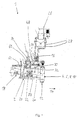
- the device 1 shown in Figures 1-3 which also as Application head or fluid delivery device is used for Dispensing and applying liquids such as adhesives, Hot melt adhesive, cold glue, sealants or the like on various Substrates.
- the device 1 comprises a metallic base body 2 and four delivery or order modules 4, 6, 8, 10, each with are screwed to the base body 2 and each of them by at least one outlet opening 12 the fluid is dispensed.
- the Order modules 4-10 can also be supplied with compressed gas Area of the outlet openings 12 exits and on through compressed gas nozzles the fluid released acts in such a way that it sprays or swirls becomes.
- the substrate to be coated is below the Outlet openings by means of conveyors, not shown, on the Device 1 guided past, for example in the direction of arrow 14.
- the device 1 can be attached to the base body 2 Fastening screws 16 are attached to support structures.
- a hose connector 18 is used to produce a Connection of the device 1 to a fluid source, not shown, such as an adhesive container for liquid adhesive.
- the adhesive is one of several Composed flow channel through the sections Base body 2 in the order modules 4-10 passed to the Outlet openings 12.
- the adhesive flow channel has a first Bore 20, which is only schematic by the dashed line is shown, a transverse distribution channel 22, with this communicating, leading to the respective modules 4-10 Oblique bores 24 and others within the order modules 4-10 trained channels that open into the outlet opening 12.
- Valve arrangement shown in detail, which a pneumatically movable from an open to a closed position Has valve body which cooperates with a valve seat.
- Actuation of the valve arrangement serves an electrically controllable Solenoid valve 26 and control air lines 28 connected to it and in the base body 2 formed compressed gas channels, which only are indicated by the dashed lines 30, 32 and for introduction serve from compressed gas in the order modules 4-10.
- compressed gas is on the Base body 2 an air connector 34 is mounted.
- the compressed gas flows through several compressed gas channels described in more detail below and serves to spray or swirl the by the Outlet opening 12 dispensed fluid.
- the Base body 2 To heat the spray gas, preferably air, are within the Base body 2 several heat transfer chambers 36, 38, 40, 42, 44, 46 formed, through which the gas flows in the direction the arrows.
- two are in series switched preheat heat transfer chambers 36, 38 and four further and parallel, one each Order module 4-10 associated heat transfer chambers 40-46 intended.
- the Heat transfer chambers 36-46 are in one plane upper section of the base body and parallel to each other arranged.
- the base body 2 is made of composed of several housing sections, which means Screw connections are attached to each other.
- everyone Housing section takes at least one heat transfer chamber and is used to attach one order module 4-10 at a time.
- each heat transfer chamber 36-46 is a fluid permeable, structure having a plurality of communicating cavities formed in the embodiment by cylindrical Sintered metal parts 48 is formed.
- the heat transfer chamber with the Fluid-permeable structures arranged therein serve primarily for Improvement of heat transfer, in the embodiment of the Heating of the fluid permeable structure flowing gas.
- the sintered sintered metal parts are in the essentially rigid and can for example be made of a bronze-copper alloy consist.
- the fluid permeable structure but also as a metal mesh, metal mesh or an open-pore rigid foam material, through which gas or Liquid can flow through.
- the sintered metal parts 48 are each cylindrical in shape and in each cylindrical bores 50 formed in the base body 2 used and fitted. The heat supply or removal is below explained in more detail.
- Each hole 50 is a through hole in the Base body 2, more precisely the housing sections formed.
- the sintered metal parts 48 are well recognizable from those in FIG. 3 Inlet ends 52 of the bores 50 insertable. Both the entrants 52 and the opposite ends 54 of the bores 50 provided with an internal thread and are in a manner not shown gas-tight in the operating state with screw-in sealing plugs locked.
- the gas introduced through the inlet port 34 flows through the heat transfer chamber 36, then through a Cross bore 56 in the heat transfer chamber 38, then through a Cross bore 58 in the heat transfer chamber 40 in the Order module 4.
- coolants could be used to cool the Base body 2 and thus to reduce the temperature of the Heat transfer chambers 36-46 and the fluid permeable structure be provided, for example by inserting into the bores 58, 60 Coolant, for example a cooled gas or a liquid Coolant is introduced.
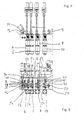
- Figure 4 shows a sectional view of an alternative Embodiment of a device 1, which is substantially similar is designed like the one previously described with reference to FIGS. 1-3 Contraption. The following are the differences from that in Figure 1-3 described device 1 is explained and otherwise Full reference to the above descriptions.
- the in Figure 4 basic body 2 takes three, not shown Order modules on which three heat transfer chambers 42, 44, 46 are assigned and can be attached in the same way, as shown with reference to Figure 3.
- Housing section 64 are two connected in series Heat transfer chambers 36, 38 formed.
- the fluid permeable Structures in the form of sintered metal parts 50 are also shown in FIG cylindrical bores 48 used.
- inlet ends 52 provided by plugs, not shown can be closed.
- the introduction of to be warmed Gas occurs through the inlet opening 66. Through cross bores 56, 58, 60 and 62 the gas can continue to the downstream Flow heat transfer chambers 42-48.
- Figure 5 shows an alternative embodiment of a Device according to the invention for dispensing fluid, in which a Liquid such as hot melt adhesive using a Heat transfer chamber 68 and one formed therein fluid permeable structure is heated or cooled.
- the fluid permeable structure is preferred, as detailed above is designed as a sintered metal part 70 in a cylindrical shape, which in a cylindrical formed in a base body 2 Bore 72 is inserted so that contact between the Sintered metal part 40 and the inner surface of the bore 72.
- the base body 2 in a manner not shown in Figure 5 with the help heated by heating means, preferably electrical heating elements or be cooled with the help of coolants, so that in the Heat transfer chamber 68 also using the sintered metal part 70 heating of the fluid-permeable structure Adhesive or cooling occurs while the adhesive is in Direction of arrows 74 from one by means of a connecting piece 18 connected fluid source through the heat transfer chamber 68 and through a downstream bore 76 to at least one Order module 4 flows, which has an outlet opening 12 for dispensing of the fluid.
- heating means preferably electrical heating elements or be cooled with the help of coolants
- Figure 6 illustrates a fluid permeable according to the invention Structure in the form of a cylindrical sintered metal part, which in one Flow channel for dispensing by means of a dispensing device 1
- Liquid or a gas can be used and for heat transfer, is preferably used for heating.
- the sintered metal part 48 can be mechanically attached to it after sintering machined outer cylinder surface, preferably turned be so that partially the pores on the lateral surface be closed due to deformation, causing a enlarged contact area is formed, which is in contact with the Inner wall of a hole is in which the sintered metal part 48th is used. This further improves the heat transfer.
- several separate ones can be used in a manner not shown Sections of sintered metal parts in a row in a row Heat transfer chamber to be placed.
- FIG. 7 shows a cartridge 71 according to the invention which is provided for this into a fluid delivery device 1, for example a device according to the descriptions above.
- the bullet 71 can be releasably attached to a heat transfer chamber 36-46 , for example with the help of sealing plugs, Bayonet locks, screw connections or the like.
- the cartridge 71 has an outer heating element 72 in the form of a hollow cylinder.
- the Heater 72 is provided with a variety of electrical conductors (not shown), which flows through the flow of an electric current Generate heat. For this purpose, electrical connections (not shown) available.
- the heating element 72 Inside the heating element 72 is the one according to the invention Fluid permeable structure in the form of a cylindrical body 74 formed, preferably as a sintered metal part, which in the inner Cavity of the hollow cylinder is fitted.
- the Cartridge 71 flows through one in the manner described above heating liquid, for example hot melt adhesive or a Gas to be heated, for example compressed air, the fluid-permeable Structure of the body 74 so that heating takes place.
- Cartridge 71 differs from that previously 7 described cartridge in that no Heating element is provided, but instead a housing in the form a tube 73 is provided, which is designed as a sintered metal part fluid permeable structure.
- the tube 73 is off, for example Made of aluminum or another good heat-conducting material.
- Grooves 76 formed in the sealing rings not shown, For example, O-rings can be inserted around one in a base body 2 formed bore Heat transfer chamber is sealed, so that too Heating fluid defined by the sintered metal part 74 fluid permeable structure flows.
- the alternative cartridge 78 shown in FIG. 9 has a center arranged electric heating element 80 and one as a hollow cylinder 82 trained fluid-permeable structure in the form of a sintered metal part on, in the inner cavity of the heating element 80 is firmly fitted.
- the cartridge 78 is equally in one Base body of a fluid delivery device 1 placed and detachable attached and the sintered metal part 80 is flowed around by fluid, so that heating takes place.
- the hot melt adhesive is in the heat transfer chamber 68 is heated and into the application module 4 initiated.
- liquid flows through the Connection piece 18 in the base body 2 and the modules 4-10 to be discharged from the outlet opening 12.
- the inner Wall of the heat transfer chambers 36-46 and the fluid permeable structure heated by means of heating means or in the case cooling with the help of coolants heated by means of heating means or in the case cooling with the help of coolants. That warmed up or cooled gas then continues to flow through the base body 2 in the Order modules 4-10 and is then heated to the the liquid to be dispensed acts as a spray, a swirl or the like.
Abstract
Description
Die Erfindung betrifft ein Verfahren zum Abgeben eines Fluids, bei dem das Fluid aus einer Fluidquelle einer Vorrichtung zum Abgeben des Fluids zugeführt und durch eine der Abgabevorrichtung zugeordneten Austrittsöffnung abgegeben wird.The invention relates to a method for dispensing a fluid, in which the fluid from a fluid source of a device for dispensing the Fluids supplied and through one assigned to the dispensing device Exit opening is released.
Die Erfindung betrifft eine Vorrichtung zum Abgeben von Fluid, mit einem mit einer Fluidquelle verbindbaren und in eine Abgabeöffnung zum Abgeben des Fluids mündenden Strömungskanal.The invention relates to a device for dispensing fluid, with a connectable to a fluid source and into a dispensing opening for dispensing the fluid flow channel.
In vielen industriellen Anwendungen werden fließfähige Materialen (Fluide) mithilfe von Fluid-Abgabevorrichtungen abgegeben und auf Substrate abgelegt oder aufgetragen. Bei den fließfähigen Materialen kann es sich beispielsweise um Klebstoffe, Lacke, Dichtungsmaterialen und bei den Substraten um Hygieneartikel, Kunststofffolien, Möbel oder Maschinenteile oder dgl. handeln. Die Abgabe der fließfähigen Materialen kann je nach Anwendungsfall beispielsweise raupen-, streifen- oder folienförmig sein, oder das Material wird gegebenenfalls mit Hilfe von einem das Fluid beeinflussenden Gasstrahl aufgesprüht. Die Fluid-Abgabevorrichtungen sind an eine Fluidquelle, beispielsweise einen Klebstoffbehälter angeschlossen und das Fluid wird mit Hilfe einer Pumpe unter Zwischenschaltung von sogenannten Auftragsventilen zu einer beispielsweise kreisförmigen oder schlitzförmigen Austrittsöffnung gefördert.Flowable materials are used in many industrial applications (Fluids) dispensed and applied using fluid dispensers Deposited or applied substrates. With the flowable materials can be, for example, adhesives, varnishes, sealing materials and for the substrates around hygiene articles, plastic films, furniture or Act machine parts or the like. The delivery of the flowable Depending on the application, materials can, for example, be strip or foil-shaped, or the material is optionally sprayed with the help of a gas jet influencing the fluid. The fluid dispensers are to a fluid source, for example an adhesive container is connected and the fluid is removed using a Pump with the interposition of so-called order valves for example a circular or slot-shaped outlet opening promoted.
Bei einigen Anwendungen ist es vorteilhaft, dass das Fluid vor der Abgabe erwärmt wird. Bei Sprühverfahren kann es vorteilhaft sein, ein auf das abzugebende Fluid einwirkendes Gas zu erwärmen. Zu diesem Zweck ist es bekannt, einen Grundkörper der Abgabevorrichtung elektrisch zu beheizen, so dass durch in dem Grundkörper ausgebildete Strömungskanäle hindurchströmende Flüssigkeit oder hindurchströmendes Gas erwärmt wird, indem es an der dem Strömungskanal begrenzenden Innenwandung zu einem Wärmeübergang durch Konvektion kommt. Zur Erwärmung eines Gases in einer Fluid-Abgabevorrichtung ist es bekannt, einen zick-zack-artig verlaufenden Strömungskanal für das Gas auszubilden. Die zick-zackartige Gestaltung dient dabei dem Zweck, den für eine Wärmeübertragung zur Verfügung stehenden Strömungsweg zu verlängern und dadurch die Wärmeübertragung zu verbessern. Nachteilig hieran ist jedoch, dass der konstruktive Aufwand für eine Herstellung eines derartigen Strömungsverlaufs sehr aufwändig und somit teuer ist.In some applications, it is advantageous that the fluid before Levy is heated. In spraying processes it can be advantageous to use a to heat gas acting on the fluid to be dispensed. To this Purpose is known, a base body of the dispenser to be electrically heated, so that formed in the base body Liquid flowing through flow channels or gas flowing therethrough is heated by the Flow channel limiting inner wall to a Heat transfer comes through convection. For heating a gas in a fluid dispenser it is known to be a zigzag training flow channel for the gas. The zigzag Design serves the purpose that for a Heat transfer available flow path too extend and thereby improve the heat transfer. The disadvantage of this, however, is that the design effort for one Production of such a flow course is very complex and is therefore expensive.
Aufgabe der vorliegenden Erfindung ist es, ein Verfahren und eine Vorrichtung der Eingangs genannten Art sowie eine Patrone anzugeben, mit denen die Wärmeübertragung verbessert wird.The object of the present invention is a method and a Specify the device of the type mentioned and a cartridge, with which the heat transfer is improved.
Die Erfindung löst die Aufgabe bei einem Verfahren der Eingangs genannten Art dadurch, dass das Fluid vor der Abgabe durch die Austrittsöffnung zur Erwärmung oder Abkühlung durch eine Wärmeübertragungskammer strömt, in welcher eine fluiddurchlässige, eine Vielzahl von kommunizierenden Hohlräumen aufweisende Struktur ausgebildet ist, die von dem Fluid umströmt wird.The invention solves the problem with an input method mentioned type in that the fluid prior to delivery by the Outlet opening for heating or cooling by a Heat transfer chamber flows in which a fluid-permeable, structure having a plurality of communicating cavities is formed, which is flowed around by the fluid.
Die Erfindung löst die Aufgabe ferner bei einer Vorrichtung der Eingangs genannten Art durch eine Wärmeübertragungskammer zum Erwärmen oder Abkühlen des Fluids, in welcher eine fluiddurchlässige, eine Vielzahl von kommunizierenden Hohlräumen aufweisende Struktur ausgebildet ist.The invention also achieves the object in an input device mentioned type by a heat transfer chamber for heating or cooling the fluid in which a fluid permeable, a Large number of communicating cavities structure is trained.
Die Vorteile des erfindungsgemäßen Verfahrens und der erfindungsgemäßen Vorrichtung bestehen darin, dass die Wärmeübertragung zum Erwärmen oder alternativ auch zum Abkühlen einer Flüssigkeit und/oder eines Gases vor der Abgabe von der Abgabevorrichtung deutlich verbessert werden kann durch die Bereitstellung der erfindungsgemäßen fluiddurchlässigen Struktur, die von dem Fluid umströmt wird. Die fluiddurchlässige Struktur ist vorzugsweise ein gesintertes Material, besonders bevorzugt ein Sintermetall, welches im wesentlichen starr ist und eine Vielzahl von miteinander verbundenen Hohlräumen aufweist, durch die das Fluid hindurchströmen kann. Der Wärmeübergang wird aufgrund der fluiddurchlässigen, im Strömungskanal der Wärmeübertragungskammer liegenden Struktur dadurch verbessert, dass die für den Wärmeübergang maßgebliche Oberfläche zwischen der Struktur und dem zu erwärmenden und gegebenenfalls auch abzukühlenden Fluid deutlich vergrößert ist, vervielfältigt ist. Die Struktur wird auf unter näher beschriebene Weise erwärmt, so dass Wärme auf das Fluid abgegeben werden kann über die große Oberfläche der Struktur. Darüber hinaus wird der Wärmeübergang dadurch verbessert, dass das Fluid während der Durchströmung der Struktur vielfach umgelenkt wird und dadurch eine gewisse Turbulenz entsteht, die für eine Verbesserung der Wärmeübertragung sorgt. Erfindungsgemäß wird somit die Wärmeübertragung, etwa die Erwärmung einer Flüssigkeit oder eines Gases deutlich verbessert und die Vorrichtung kann dadurch relativ kompakt gebaut werden. Insbesondere bei der Erwärmung von Druckgas für Abgabevorrichtungen zum Versprühen von Flüssigkeiten wie Heißschmelzklebstoff sind die aufgrund der fluiddurchlässigen Struktur gegenüber einem freien Strömungskanal vergrößerten Strömungswiderstände vernachlässigbar. Das bevorzugte Sintermetall weist den Vorteil auf, dass es eine große innere Wärmeübertragungsoberfläche aufweist, formstabil ist, sich einfach herstellen und verarbeiten und somit an die jeweiligen Anwendungsfälle anpassen lässt. Alternativ können aber erfindungsgemäß auch andere offenporige vorzugsweise im wesentlichen starre Strukturen wie Gewebe, Metallgeflechte oder starre, offenporige Schaumstoffe eingesetzt werden.The advantages of the method and the Device according to the invention consist in that the Heat transfer for heating or alternatively for cooling a liquid and / or a gas prior to delivery from the Dispensing device can be significantly improved by the Provision of the fluid-permeable structure according to the invention, the is flowed around by the fluid. The fluid permeable structure is preferably a sintered material, particularly preferably a Sintered metal, which is essentially rigid and a variety of interconnected cavities through which the fluid can flow through. The heat transfer is due to the fluid permeable, in the flow channel of the heat transfer chamber lying structure improved that the for Relevant surface heat transfer between the structure and the fluid to be heated and possibly also cooled is significantly enlarged, reproduced. The structure is closer to below described way heated so that heat is given off to the fluid can be over the large surface of the structure. Furthermore the heat transfer is improved in that the fluid during the flow through the structure is deflected in many ways and thereby a certain amount of turbulence arises, which improves the Ensures heat transfer. According to the invention Heat transfer, such as heating a liquid or a Gases improved significantly and the device can be relative be built compact. Especially when heating Pressurized gas for dispensing devices for spraying liquids they are like hot melt adhesive due to the fluid permeability Structure enlarged compared to a free flow channel Flow resistances negligible. The preferred sintered metal has the advantage that it is a large inner Has heat transfer surface, is dimensionally stable, easy manufacture and process and thus to the respective applications can be adjusted. Alternatively, however, others can also be used according to the invention open-pore, preferably essentially rigid structures such as Fabrics, metal mesh or rigid, open-cell foams be used.
In vorteilhafter Weise kann das Fluid bei Durchströmen der Wärmeübertragungskammer erwärmt oder gekühlt und gleichzeitig durch die fluiddurchlässige Struktur gefiltert werden, so dass zusätzlich zur Erwärmung eine Reinigung eines Gases oder einer Flüssigkeit vorgenommen wird.The fluid can advantageously flow through the Heat transfer chamber heated or cooled and at the same time be filtered through the fluid permeable structure, so that in addition for heating a cleaning of a gas or a liquid is made.
Zur Einbringung von Wärme bzw. Abtransport von Wärme von dem Fluid steht die fluiddurchlässige Struktur vorzugsweise in Kontakt mit der inneren Oberfläche der Wärmeübertragungskammer. Dadurch findet ein effizienter Wärmetransport statt.For the introduction of heat or removal of heat from the The fluid-permeable structure is preferably in contact with the fluid inner surface of the heat transfer chamber. This takes one efficient heat transfer instead.
Besonders bevorzugt ist es, dass das Fluid eine Flüssigkeit, insbesondere ein fließfähiger Kunststoff wie Heißschmelzklebstoff ist und durch Durchströmen durch die Wärmeübertragungskammer erwärmt wird. Gleichermaßen bevorzugt ist, dass das Fluid ein Gas, vorzugsweise Luft ist und durch Durchströmen durch die Wärmeübertragungskammer erwärmt wird, was bei Sprühapplikationen vorteilhaft ist.It is particularly preferred that the fluid is a liquid, is in particular a flowable plastic such as hot melt adhesive and by flowing through the heat transfer chamber is heated. It is equally preferred that the fluid is a gas, is preferably air and by flowing through it Heat transfer chamber is heated, resulting in spray applications is advantageous.
Die erfindungsgemäße Vorrichtung wird dadurch auf konstruktiv einfache Weise weitergebildet, dass die Wärmeübertragungskammer durch einen Abschnitt des Strömungskanals gebildet ist, in welchen die fluiddurchlässige Struktur eingesetzt ist. Somit kann in einem in einem Gehäuse oder Grundkörper der Abgabevorrichtung ausgebildeten Strömungskanal durch Einsetzen einer erfindungsgemäßen fluiddurchlässigen Struktur auf einfache Weise die Wärmeübertragung verbessert werden.The device according to the invention is thereby constructive simply trained that the heat transfer chamber is formed by a section of the flow channel in which the fluid permeable structure is used. Thus, in one in one Housing or base body of the dispenser Flow channel by inserting an inventive fluid-permeable structure to easily transfer heat be improved.
Besonders bevorzugt ist es, dass die fluiddurchlässige Struktur im wesentlichen als zylindrischer Körper ausgebildet ist, der in eine im wesentlichen zylindrische Bohrung eingesetzt ist, weil so eine einfache Herstellung und Montage und auch Austausch der fluiddurchlässigen Struktur möglich ist.It is particularly preferred that the fluid-permeable structure in the is essentially designed as a cylindrical body which in a essential cylindrical bore is used because such a simple Production and assembly and also replacement of the fluid-permeable Structure is possible.
Ein weiterer Vorteil ergibt sich dadurch, dass die fluiddurchlässige Struktur ein mechanisch nachbearbeitetes Sintermetallteil ist, vorzugsweise ein gedrehtes Sintermetallteil. Durch eine mechanische Bearbeitung, etwa Drehen einer mit der Wärmeübertragungskammer in Kontakt stehenden Oberfläche des Sintermetallteils wird der Wärmeübergang zwischen Sintermetallteil und Wärmeübertragungskammer weiter verbessert. Durch das Drehen werden die äußeren Poren teilweise verschlossen und eine größere Kontaktfläche hergestellt, ohne das die innere von Fluid durchströmte Struktur nachteilig beeinflusst wird.Another advantage results from the fact that the fluid-permeable Structure is a mechanically refurbished sintered metal part, preferably a turned sintered metal part. By a mechanical Machining, such as turning one with the heat transfer chamber in Contact surface of the sintered metal part Heat transfer between the sintered metal part and Heat transfer chamber further improved. By turning the outer pores are partially closed and a larger one Made contact area without the internal flow of fluid Structure is adversely affected.
Zweckmäßigerweise ist die Wärmeübertragungskammer in einem aus Metall bestehenden Gehäuse ausgebildet und sind in dem Gehäuse Heizmittel zum Beheizen des Gehäuses angeordnet.The heat transfer chamber is expediently in one Metal formed housing and are in the housing Heating means arranged for heating the housing.
Besonders bevorzugt ist es, dass die fluiddurchlässige Struktur als Teil einer in die Vorrichtung einsetzbaren Patrone ausgebildet ist, die lösbar an der Vorrichtung befestigbar ist und von dem Fluid durchströmt wird. Dadurch kann auf einfache Weise rasch ein Austausch vorgenommen werden. Zweckmäßigerweise weist die Patrone mindestens ein Heizelement auf.It is particularly preferred that the fluid-permeable structure is part a cartridge that can be inserted into the device is designed to be detachable can be attached to the device and the fluid flows through it. This allows an exchange to be carried out quickly and easily become. The cartridge expediently has at least one Heating element on.
Gemäß einer alternativen Ausführungsform wird vorgeschlagen, dass sie einen Grundkörper aufweist, in dem die eine oder mehrere Wärmeübertragungskammer / Wärmeübertragungskammern angeordnet sind und mindestens ein oder mehrere an dem Grundkörper montierte Auftragsmodule vorgesehen sind, die die Austrittsöffnung zum Abgeben des Fluids aufweisen. Bei Bedarf können mehrere Wärmeübertragungskammern in Reihe oder parallel geschaltet werden, die vorzugsweise in separaten Gehäuseabschnitten angeordnet sind, die aneinander befestigbar sind.According to an alternative embodiment, it is proposed that it has a base body in which the one or more Heat transfer chamber / heat transfer chambers arranged are and at least one or more mounted on the base body Order modules are provided, which the outlet opening for dispensing of the fluid. If necessary, several Heat transfer chambers can be connected in series or in parallel, which are preferably arranged in separate housing sections, that can be attached to each other.
Weitere vorteilhafte Weiterbildungen sind in den Unteransprüchen angegeben.Further advantageous developments are in the subclaims specified.
Die Erfindung ist nachstehend anhand von bevorzugten Ausführungsbeispielen unter Bezugnahme auf die beigefügten Zeichnungen beschrieben. Es zeigen:
- Figur 1
- eine erfindungsgemäße Fluid-Abgabevorrichtung in einer Seitenansicht;
Figur 2- die Vorrichtung gemäß Figur 1 in einer weiteren Seitenansicht;
- Figur 3
- die Vorrichtung gemäß Figur 1 in einer Teilschnittdarstellung;
Figur 4- eine alternative Ausführungsform von mehreren Wärmeübertragungskammern für eine Vorrichtung gemäß Figur 1;
- Figur 5
- eine alternative Ausführungsform einer Vorrichtung zum Abgeben von Fluid, welches erfindungsgemäß erwärmt werden kann;
Figur 6- ein zylindrisches Seitenmetallteil in perspektivischer Darstellung;
Figur 7- eine Patrone für die Fluid-Abgabevorrichtung in perspektivischer Darstellung;
Figur 8- eine alternative Ausführungsform einer Patrone in perspektivischer Darstellung; und
- Figur 9
- eine weitere alternative Ausführungsform einer Patrone
- Figure 1
- a fluid delivery device according to the invention in a side view;
- Figure 2
- the device of Figure 1 in a further side view;
- Figure 3
- the device of Figure 1 in a partial sectional view;
- Figure 4
- an alternative embodiment of several heat transfer chambers for a device according to Figure 1;
- Figure 5
- an alternative embodiment of a device for dispensing fluid which can be heated according to the invention;
- Figure 6
- a cylindrical side metal part in a perspective view;
- Figure 7
- a cartridge for the fluid dispenser in perspective;
- Figure 8
- an alternative embodiment of a cartridge in perspective; and
- Figure 9
- another alternative embodiment of a cartridge
Die in den Figuren 1-3 dargestellte Vorrichtung 1, die auch als
Auftragskopf oder Fluid-Abgabevorrichtung bezeichnet wird, dient zum
Abgeben und Auftragen von Flüssigkeiten wie Klebstoffen,
Heißschmelzklebstoff, Kaltleim, Dichtstoffen oder dgl. auf verschiedene
Substrate. Die Vorrichtung 1 umfasst einen metallischen Grundkörper 2
und vier Abgabe- oder Auftragsmodule 4, 6, 8, 10 auf, die jeweils mit
dem Grundkörper 2 verschraubt sind und von denen jeweils durch
mindestens eine Austrittsöffnung 12 das Fluid abgegeben wird. Den
Auftragsmodulen 4-10 kann auch Druckgas zugeführt werden, das im
Bereich der Austrittsöffnungen 12 durch Druckgasdüsen austritt und auf
das abgegebene Fluid so einwirkt, dass es versprüht oder verwirbelt
wird. Das zu beschichtende Substrat wird unterhalb der
Austrittsöffnungen mittels nicht dargestellter Fördereinrichtungen an der
Vorrichtung 1 vorbeigeführt, beispielsweise in Richtung des Pfeils 14.
Die Vorrichtung 1 kann mittels an dem Grundkörper 2 befestigter
Befestigungsschrauben 16 an Tragstrukturen befestigt werden.The device 1 shown in Figures 1-3, which also as
Application head or fluid delivery device is used for
Dispensing and applying liquids such as adhesives,
Hot melt adhesive, cold glue, sealants or the like on various
Substrates. The device 1 comprises a
Ein Schlauchanschlussstutzen 18 dient zur Herstellung einer
Verbindung der Vorrichtung 1 mit einer nicht dargestellten Fluidquelle,
etwa einem Klebstoffbehälter für flüssigen Klebstoff. In an sich
bekannter Weise wird der Klebstoff durch einen aus mehreren
Abschnitten zusammengesetzten Strömungskanal durch den
Grundkörper 2 in die Auftragsmodule 4-10 geleitet bis hin zu den
Austrittsöffnungen 12. Der Klebstoff-Strömungskanal weist eine erste
Bohrung 20 auf, die lediglich schematisch durch die gestrichelte Linie
dargestellt ist, einen Querverteilungskanal 22, mit diesem
kommunizierende, zu den jeweiligen Modulen 4-10 führende
Schrägbohrungen 24 sowie weitere innerhalb der Auftragsmodule 4-10
ausgebildete Kanäle, die in die Austrittsöffnung 12 münden.A
Zur wahlweisen Unterbrechung bzw. Freigabe der Strömung des
Klebstoffs innerhalb der Vorrichtung 1 ist in jedem Modul 4-10 eine nicht
näher dargestellte Ventilanordnung ausgebildet, welche einen
pneumatisch aus einer Öffnungs- in eine Schließstellung bewegbaren
Ventilkörper aufweist, der mit einem Ventilsitz zusammenwirkt. Zur
Betätigung der Ventilanordnung dient ein elektrisch ansteuerbares
Magnetventil 26 sowie mit diesem verbundene Steuerluftleitungen 28
sowie in dem Grundkörper 2 ausgebildete Druckgaskanäle, die lediglich
durch die gestrichelten Linien 30, 32 angedeutet sind und zur Einleitung
von Druckgas in die Auftragsmodule 4-10 dienen.For optional interruption or release of the flow of the
Adhesive within device 1 is not one in each module 4-10
Valve arrangement shown in detail, which a
pneumatically movable from an open to a closed position
Has valve body which cooperates with a valve seat. to
Actuation of the valve arrangement serves an electrically
Zur Zuführung von Gas, im Ausführungsbeispiel Druckgas ist an dem
Grundkörper 2 ein Luftanschlussstutzen 34 montiert. Das Druckgas
durchströmt mehrere nachfolgend näher beschriebene Druckgaskanäle
und dient zum Versprühen oder Verwirbeln des durch die
Austrittsöffnung 12 abgegebenen Fluids.For supplying gas, in the exemplary embodiment compressed gas is on the
Zur Erwärmung des Sprüh-Gases, vorzugsweise Luft, sind innerhalb des
Grundkörpers 2 mehrere Wärmeübertragungskammern 36, 38, 40, 42,
44, 46 ausgebildet, die von dem Gas durchströmt werden in Richtung
der eingezeichneten Pfeile. Im Ausführungsbeispiel sind zwei in Reihe
geschaltete Vorwärm-Wärmeübertragungskammern 36, 38 und vier
weitere sowie parallel zueinander geschaltete, jeweils einem
Auftragsmodul 4-10 zugeordnete Wärmeübertragungskammern 40-46
vorgesehen. Alternativ können jedoch je nach Anwendungsfall
unterschiedlich viele in Reihe oder parallel geschalteter
Wärmeübertragungskammern oder auch eine einzelne
Wärmeübertragungskammer vorgesehen sein. Die
Wärmeübertragungskammern 36-46 sind in einer Ebene liegend im
oberen Abschnitt des Grundkörpers und jeweils parallel zueinander
angeordnet. Wie die Figuren 2 und 3 zeigen, ist der Grundkörper 2 aus
mehreren Gehäuseabschnitten zusammengesetzt, die mittels
Schraubverbindungen aneinander befestigt sind. Jeder
Gehäuseabschnitt nimmt mindestens eine Wärmeübertragungskammer
auf und dient zur Befestigung jeweils eines Auftragsmoduls 4-10.To heat the spray gas, preferably air, are within the
In jeder Wärmeübertragungskammer 36-46 ist eine fluiddurchlässige,
eine Vielzahl von kommunizierenden Hohlräumen aufweisende Struktur
ausgebildet, die im Ausführungsbeispiel durch zylindrische
Sintermetallteile 48 gebildet ist. Die Wärmeübertragungskammer mit den
darin angeordneten fluiddurchlässigen Strukturen dienen primär zur
Verbesserung der Wärmeübertragung, im Ausführungsbeispiel der
Erwärmung des durch die fluiddurchlässige Struktur
hindurchströmenden Gases. Die gesinterten Sintermetallteile sind im
wesentlichen starr und können beispielsweise aus einer Bronze-Kupfer-Legierung
bestehen. Alternativ kann die fluiddurchlässige Struktur
jedoch auch als Metallgewebe, Metallgeflecht oder einem offenporigen
starren Schaumstoffmaterial bestehen, durch welches Gas oder
Flüssigkeit hindurchströmen kann.In each heat transfer chamber 36-46 is a fluid permeable,
structure having a plurality of communicating cavities
formed in the embodiment by cylindrical
Die Sintermetallteile 48 sind jeweils zylindrisch geformt und in jeweils
zylindrische, in dem Grundkörper 2 ausgebildete Bohrungen 50
eingesetzt und eingepasst. Die Wärmezufuhr bzw. Abfuhr ist unten
näher erläutert. Jede Bohrung 50 ist als Durchgangsbohrung in dem
Grundkörper 2, genauer gesagt deren Gehäuseabschnitten ausgebildet.
Die Sintermetallteile 48 sind von den in Figur 3 gut erkennbaren
Einlassenden 52 der Bohrungen 50 einführbar. Sowohl die Einlassenden
52 als auch die gegenüberliegenden Enden 54 der Bohrungen 50 sind
mit einem Innengewinde versehen und sind in nicht dargestellter Weise
im Betriebszustand mit einschraubbaren Verschlussstopfen gasdicht
verschlossen. Das durch den Einlassstutzen 34 eingeleitete Gas strömt
durch die Wärmeübertragungskammer 36, dann durch eine
Querbohrung 56 in die Wärmeübertragungskammer 38, dann durch eine
Querbohrung 58 in die Wärmeübertragungskammer 40 in das
Auftragsmodul 4. Ferner strömt Gas weiter durch die weiteren
Querbohrungen 60, 62, 64 jeweils in die Wärmeübertragungskammern
42, 44 bzw. 46 und dann in die jeweils zugehörigen Auftragsmodule 6, 8,
10. Zum Austauschen der Sintermetallteile 48 werden die in die
Einlassenden 52 eingeschraubten Verschlussstopfen entfernt und die
Sintermetallteile herausgeholt, gegebenenfalls unter zu Hilfenahme von
Werkzeugen, die durch die gegenüberliegenden Enden 54 eingeführt
werden können, um die Sintermetallteile 48 herauszudrücken.The
Zur Zuführung von Wärme zu den Wärmeübertragungskammern 36-46
und den fluiddurchlässigen Strukturen (Sintermetallteile 48) sind
elektrische Widerstandsheizungen innerhalb des Grundkörpers 2
angeordnet, namentlich innerhalb von mehreren Heiz-Bohrungen 58, 60,
wie Figur 1 zeigt. In nicht dargestellter Weise sind elektrische
Widerstandsheizungen in zylindrischer Form in die Bohrungen 58, 60
eingesetzt und werden von elektrischem Strom durchflossen, der durch
Anschlüsse 62 zu den Bohrungen 58, 60 geführt wird. Die
Widerstandsheizungen bilden Heizmittel zum Beheizen des
Grundkörpers 2. Durch Wärmeleitung wird Wärmeenergie durch den
Grundkörper 2 transportiert, so dass auch die jeweiligen
Wärmeübertragungskammern 36-46 und die in diese eingesetzten
fluiddurchlässigen Strukturen auf eine solche Temperatur erwärmt
werden können, dass Wärmeenergie auf das durch die fluiddurchlässige
Struktur hindurchströmende Gas übergeht und dieses erwärmt wird.
Durch die fluiddurchlässige Struktur wird der Wärmeübergang deutlich
verbessert, da die für die Wärmeübertragung zur Verfügung stehende
Oberfläche erheblich vergrößert ist und das die Struktur umströmende
Gas umgelenkt und dadurch verwirbelt wird, was gewisse Turbulenzen
verursacht, die den Wärmeübergang fördern. In nicht dargestellter
Weise könnten anstelle der Heizmittel Kühlmittel zum Kühlen des
Grundkörpers 2 und somit zum Verringern der Temperatur der
Wärmeübertragungskammern 36-46 und der fluiddurchlässigen Struktur
vorgesehen sein, beispielsweise indem in die Bohrungen 58, 60 ein
Kühlmittel, beispielsweise ein gekühltes Gas oder ein flüssiges
Kühlmittel eingeführt wird.For supplying heat to the heat transfer chambers 36-46
and the fluid permeable structures (sintered metal parts 48)
electrical resistance heating within the
Figur 4 zeigt eine Schnittdarstellung eines alternativen
Ausführungsbeispiels einer Vorrichtung 1, die im wesentlichen ähnlich
gestaltet ist wie die zuvor anhand der Figuren 1-3 beschriebene
Vorrichtung. Nachfolgend sind die Unterschiede zu der in Figur 1-3
beschriebenen Vorrichtung 1 erläutert und ansonsten wird
vollumfänglich auf die obigen Beschreibungen Bezug genommen. Der in
Figur 4 dargestellte Grundkörper 2 nimmt drei nicht dargestellte
Auftragsmodule auf, denen drei Wärmeübertragungskammern 42, 44,
46 zugeordnet sind und auf dieselbe Weise befestigt werden können,
wie anhand von Figur 3 dargestellt ist. In einem in Figur 4 linken
Gehäuseabschnitt 64 sind zwei in Reihe hintereinander geschaltete
Wärmeübertragungskammern 36, 38 ausgebildet. Die fluiddurchlässigen
Strukturen in Form von Sintermetallteilen 50 sind ebenfalls in
zylindrische Bohrungen 48 eingesetzt. Hierzu sind Einlass-Enden 52
vorgesehen, die durch nicht dargestellte Verschlussstopfen
verschlossen werden können. Die Einführung von zu erwärmenden
Gases erfolgt durch die Eintassöffnung 66. Durch Querbohrungen 56,
58, 60 und 62 kann das Gas weiter zu den jeweils nachgeschalteten
Wärmeübertragungskammern 42-48 strömen.Figure 4 shows a sectional view of an alternative
Embodiment of a device 1, which is substantially similar
is designed like the one previously described with reference to FIGS. 1-3
Contraption. The following are the differences from that in Figure 1-3
described device 1 is explained and otherwise
Full reference to the above descriptions. The in
Figure 4
Figur 5 zeigt ein alternatives Ausführungsbeispiel einer
erfindungsgemäßen Vorrichtung zum Abgeben von Fluid, bei der eine
Flüssigkeit wie Heißschmelzklebstoff mittels einer
Wärmeübertragungskammer 68 und einer darin ausgebildeten
fluiddurchlässigen Struktur erwärmt oder abgekühlt wird. Die
fluiddurchlässige Struktur ist vorzugsweise, wie oben ausführlich
erläutert ist, als Sintermetallteil 70 in zylindrischer Form ausgebildet,
welches in eine in einem Grundkörper 2 ausgebildeten zylindrischen
Bohrung 72 eingesetzt ist, so dass ein Kontakt zwischen dem
Sintermetallteil 40 und der inneren Oberfläche der Bohrung 72 besteht.
Wie ebenfalls zuvor anhand des ersten Ausführungsbeispiels erläutert
ist, auf dessen Beschreibungen vollumfänglich Bezug genommen wird,
kann der Grundkörper 2 in in Figur 5 nicht dargestellter Weise mit Hilfe
von Heizmitteln, vorzugsweise elektrischen Heizelementen erwärmt oder
mit Hilfe von Kühlmitteln gekühlt werden, so dass in der
Wärmeübertragungskammer 68 auch mit Hilfe des Sintermetallteils 70
eine Erwärmung des die fluiddurchlässige Struktur umströmenden
Klebstoffs oder eine Abkühlung erfolgt, während der Klebstoff in
Richtung der Pfeile 74 aus einer mittels einer Anschlussstutzens 18
verbundenen Fluidquelle durch die Wärmeübertragungskammer 68 und
durch eine nachgeschaltete Bohrung 76 zu mindestens einem
Auftragsmodul 4 strömt, welches eine Austrittsöffnung 12 zum Abgeben
des Fluids aufweist.Figure 5 shows an alternative embodiment of a
Device according to the invention for dispensing fluid, in which a
Liquid such as hot melt adhesive using a
Figur 6 veranschaulicht eine erfindungsgemäße, fluiddurchlässige
Struktur in Form eines zylindrischen Sintermetallteils, welches in einen
Strömungskanal für mittels einer Abgabevorrichtung 1 abzugebenen
Flüssigkeit oder eines Gases einsetzbar ist und zur Wärmeübertragung,
vorzugsweise zum Erwärmen verwendet wird. Gleichzeitig kann auch
eine Filterung der Flüssigkeit oder des Gases vorgenommen werden.
Das Sintermetallteil 48 kann nach der Sinterung mechanisch an seiner
äußeren Zylindermantelfläche bearbeitet, vorzugsweise gedreht worden
sein, so dass teilweise die an der Mantelfläche befindlichen Poren
aufgrund von Verformungen geschlossen werden, wodurch eine
vergrößerte Kontaktfläche gebildet ist, die in Kontakt mit der
Innenwandung einer Bohrung steht, in die das Sintermetallteil 48
eingesetzt ist. Dadurch wird der Wärmeübergang weiter verbessert.
Alternativ können in nicht dargestellter Weise auch mehrere separate
Abschnitte von Sintermetallteilen hintereinander in Reihe in einer
Wärmeübertragungskammer platziert werden.Figure 6 illustrates a fluid permeable according to the invention
Structure in the form of a cylindrical sintered metal part, which in one
Flow channel for dispensing by means of a dispensing device 1
Liquid or a gas can be used and for heat transfer,
is preferably used for heating. At the same time, too
filtering the liquid or the gas.
The
Figur 7 zeigt eine erfindungsgemäße Patrone 71, die dafür vorgesehen
ist, in eine Fluid-Abgabevorrichtung 1, beispielsweise eine Vorrichtung
gemäß den obigen Beschreibungen, eingesetzt zu werden. Die Patrone
71 kann lösbar in einer Wärmeübertragungskammer 36-46 befestigt
werden, beispielsweise auch mit Hilfe von Verschlussstopfen,
Bajonettverschlüssen, Verschraubungen oder dgl. Die Patrone 71 weist
ein äußeres Heizelement 72 in Form eines Hohlzylinders auf. Das
Heizelement 72 ist mit einer Vielzahl von elektrischen Leitern (nicht
dargestellt) durchzogen, die bei Strömung eines elektrischen Stroms
Wärme erzeugen. Hierzu sind elektrische Anschlüsse (nicht dargestellt)
vorhanden. Im inneren des Heizelements 72 ist die erfindungsgemäße
fluiddurchlässige Struktur in Form eines zylindrischen Körpers 74
ausgebildet, vorzugsweise als Sintermetallteil, welches in den inneren
Hohlraum des Hohlzylinders eingepasst ist. Im eingesetzten Zustand der
Patrone 71 durchströmt auf die zuvor beschriebene Weise eine zu
erwärmende Flüssigkeit, beispielsweise Heißschmelzklebstoff oder ein
zu erwärmendes Gas, beispielsweise Druckluft die fluiddurchlässige
Struktur des Körpers 74, so dass eine Erwärmung erfolgt.FIG. 7 shows a
Das in Figur 8 dargestellte alternative Ausführungsbeispiel einer
erfindungsgemäßen Patrone 71 unterscheidet sich von der zuvor
anhand von Figur 7 beschriebenen Patrone 70 dadurch, dass kein
Heizelement vorgesehen ist, sondern stattdessen ein Gehäuse in Form
einer Röhre 73 vorgesehen ist, die als Sintermetallteil ausgebildete
fluiddurchlässige Struktur aufnimmt. Die Röhre 73 ist beispielsweise aus
Aluminium oder einem anderen gut wärmeleitenden Material hergestellt.
An der äußeren Mantelfläche der Röhre 73 sind in den Endabschnitten 2
Nuten 76 ausgebildet, in die in nicht dargestellter Weise Dichtungsringe,
zum Beispiel O-Ringe eingelegt werden können um gegenüber einer in
einem Grundkörper 2 ausgebildeten Bohrung der
Wärmeübertragungskammer eine Abdichtung erfolgt, so dass das zu
erwärmende Fluid definiert durch die als Sintermetallteil 74 ausgebildete
fluiddurchlässige Struktur strömt.The alternative embodiment shown in Figure 8
Die in Figur 9 dargestellte alternative Patrone 78 weist ein mittig
angeordnetes elektrisches Heizelement 80 und eine als Hohlzylinder 82
ausgebildete fluiddurchlässige Struktur in Form eines Sintermetallteils
auf, in deren inneren Hohlraum das Heizelement 80 fest eingepasst ist.
Wie zuvor erläutert, wird die Patrone 78 gleichermaßen in einem
Grundkörper einer Fluid-Abgabevorrichtung 1 platziert und lösbar
befestigt und das Sintermetallteil 80 wird von Fluid umströmt, so dass
eine Erwärmung erfolgt.The
Bei dem in Figur 5 gezeigten Beispiel wird der Heißschmelzklebstoff in
der Wärmeübertragungskammer 68 erwärmt und in das Auftragsmodul 4
eingeleitet.In the example shown in Figure 5, the hot melt adhesive is in
the
Die Betriebsweise bzw. das erfindungsgemäße Verfahren ist wie folgt:The mode of operation and the method according to the invention are as follows:
Wie in Figur 1-3 veranschaulicht strömt Flüssigkeit durch den
Anschlussstutzen 18 in den Grundkörper 2 und die Module 4-10 ein, um
von der Austrittsöffnung 12 abgegeben zu werden. Gas strömt durch
den Anschlussstutzen 34 in den Grundkörper 2 ein und wird
erfindungsgemäß durch Durchströmen der
Wärmeübertragungskammern 36-46, ggf. unter Verwendung von
Patronen gemäß den Figuren 6-9 erwärmt. Hierzu wird die innere
Wandung der Wärmeübertragungskammern 36-46 und die
fluiddurchlässige Struktur mit Hilfe von Heizmitteln erwärmt oder im Falle
einer Abkühlung mit Hilfe von Kühlmitteln gekühlt. Das erwärmte oder
abgekühlte Gas strömt dann weiter durch den Grundkörper 2 in die
Auftragsmodule 4-10 und wird dann in erwärmter Form auf die
abzugebende Flüssigkeit einwirken, dass ein Versprühen, ein Verwirbeln
oder dgl. erfolgt.As illustrated in Figure 1-3, liquid flows through the
Claims (33)
dadurch gekennzeichnet, dass die fluiddurchlässige Struktur im wesentlichen starr ist und aus einem gesinterten Material, einem Sintermetall, einem gewebten Material, einem Metallgewebe oder einem Schaumstoff besteht.Method according to claim 1,
characterized in that the fluid permeable structure is substantially rigid and consists of a sintered material, a sintered metal, a woven material, a metal mesh or a foam.
dadurch gekennzeichnet, dass das Fluid bei Durchströmen der Wärmeübertragungskammer (36-46) erwärmt oder gekühlt und gleichzeitig durch die fluiddurchlässige Struktur gefiltert wird.Method according to claim 1 or 2,
characterized in that the fluid is heated or cooled as it flows through the heat transfer chamber (36-46) and at the same time is filtered through the fluid-permeable structure.
dadurch gekennzeichnet, dass die innere Oberfläche der Wärmeübertragungskammer (36-46) auf eine gegenüber dem einströmenden Fluid erhöhten oder erniedrigten Temperatur gebracht wird und die fluiddurchlässige Struktur in Kontakt mit der inneren Oberfläche der Wärmeübertragungskammer (36-46) steht.Method according to one of the preceding claims,
characterized in that the inner surface of the heat transfer chamber (36-46) is brought to a temperature which is higher or lower than the inflowing fluid and the fluid-permeable structure is in contact with the inner surface of the heat transfer chamber (36-46).
dadurch gekennzeichnet, dass das Fluid durch mehrere in Reihe oder parallel geschaltete Wärmeübertragungskammern (36-46) strömt, um erwärmt oder gekühlt zu werden. Method according to at least one of the preceding claims,
characterized in that the fluid flows through a plurality of heat transfer chambers (36-46) connected in series or in parallel to be heated or cooled.
dadurch gekennzeichnet, dass das Fluid eine Flüssigkeit, insbesondere ein fließfähiger Kunststoff wie Heißschmelzklebstoff ist und durch Durchströmen durch die Wärmeübertragungskammer (36-46) erwärmt wird.Method according to one of the preceding claims,
characterized in that the fluid is a liquid, in particular a flowable plastic such as hot-melt adhesive, and is heated by flowing through the heat transfer chamber (36-46).
dadurch gekennzeichnet, dass das Fluid ein Gas, vorzugsweise Luft ist und durch Durchströmen durch die Wärmeübertragungskammer (36-46) erwärmt wird.Method according to one of the preceding claims,
characterized in that the fluid is a gas, preferably air, and is heated by flowing through the heat transfer chamber (36-46).
mit einem mit einer Fluidquelle verbindbaren und in eine Austrittsöffnung (12) zum Abgeben des Fluids mündenden Strömungskanal,
gekennzeichnet durch eine Wärmeübertragungskammer (36-46) zum Erwärmen oder Abkühlen des Fluids, in welcher eine fluiddurchlässige, eine Vielzahl von kommunizierenden Hohlräumen aufweisende Struktur ausgebildet ist.Fluid delivery device,
with a flow channel that can be connected to a fluid source and opens into an outlet opening (12) for dispensing the fluid,
characterized by a heat transfer chamber (36-46) for heating or cooling the fluid, in which a fluid-permeable structure having a plurality of communicating cavities is formed.
dadurch gekennzeichnet, dass die fluiddurchlässige Struktur aus einem gesinterten Material, einem Sintermetall, einem gewebten Material, einem Metallgewebe oder einem offenporigen, im wesentlichen starren Schaumstoff besteht.Device according to claim 8,
characterized in that the fluid-permeable structure consists of a sintered material, a sintered metal, a woven material, a metal mesh or an open-pore, essentially rigid foam.
dadurch gekennzeichnet, dass die Wärmeübertragungskammer (36-46) durch einen Abschnitt des Strömungskanals gebildet ist, in welchen die fluiddurchlässige Struktur eingesetzt ist.Device according to claim 9,
characterized in that the heat transfer chamber (36-46) is formed by a section of the flow channel in which the fluid-permeable structure is inserted.
dadurch gekennzeichnet, dass die fluiddurchlässige Struktur im wesentlichen als zylindrischer Körper ausgebildet ist, der in eine im wesentlichen zylindrische Bohrung (50) eingesetzt ist. Device according to claim 10,
characterized in that the fluid-permeable structure is essentially designed as a cylindrical body which is inserted into a substantially cylindrical bore (50).
dadurch gekennzeichnet, dass die fluiddurchlässige Struktur ein mechanisch nachbearbeitetes Sintermetallteil ist, vorzugsweise ein gedrehtes Sintermetallteil.Device according to claim 11,
characterized in that the fluid-permeable structure is a mechanically reworked sintered metal part, preferably a turned sintered metal part.
dadurch gekennzeichnet, dass die Wärmeübertragungskammer (36-46) in einem aus Metall bestehenden Gehäuse (2) ausgebildet ist und in dem Gehäuse (2) Heizmittel zum Beheizen des Gehäuses (2) angeordnet sind.Device according to one of the preceding claims,
characterized in that the heat transfer chamber (36-46) is formed in a housing (2) made of metal and heating means for heating the housing (2) are arranged in the housing (2).
dadurch gekennzeichnet, dass die fluiddurchlässige Struktur in Kontakt mit der Innenwandung der Bohrung (50) steht und in diese eingepasst ist.Device according to one of the preceding claims,
characterized in that the fluid permeable structure is in contact with and is fitted into the inner wall of the bore (50).
dadurch gekennzeichnet, dass die fluiddurchlässige Struktur als Teil einer in die Vorrichtung (1) einsetzbaren Patrone (70, 78) ausgebildet ist, die lösbar an der Vorrichtung (1) befestigbar ist und von dem Fluid durchströmt wird.Device according to at least one of the preceding claims,
characterized in that the fluid-permeable structure is formed as part of a cartridge (70, 78) which can be inserted into the device (1) and which can be detachably attached to the device (1) and through which the fluid flows.
dadurch gekennzeichnet, dass die Patrone (70, 78) mindestens ein Heizelement (80) aufweist.Device according to claim 15,
characterized in that the cartridge (70, 78) has at least one heating element (80).
dadurch gekennzeichnet, dass das Heizelement (80) mittig innerhalb der Patrone (78) angeordnet ist und die fluiddurchlässige Struktur das Heizelement (80) umgibt.Device according to claim 16,
characterized in that the heating element (80) is arranged centrally within the cartridge (78) and the fluid-permeable structure surrounds the heating element (80).
dadurch gekennzeichnet, dass das Heizelement (80) im wesentlichen als zylindrischer Körper und die fluiddurchlässige Struktur als den zylindrischen Körper umschließender Hohlzylinder ausgebildet ist.Device according to claim 17,
characterized in that the heating element (80) is designed essentially as a cylindrical body and the fluid-permeable structure as a hollow cylinder enclosing the cylindrical body.
dadurch gekennzeichnet, dass das Heizelement (72) im wesentlichen als Hohlzylinder ausgebildet ist und die fluiddurchlässige Struktur im inneren des Hohlzylinders angeordnet ist.Device according to claims 17 and 18,
characterized in that the heating element (72) is essentially designed as a hollow cylinder and the fluid-permeable structure is arranged in the interior of the hollow cylinder.
dadurch gekennzeichnet, dass sie einen Grundkörper (2) aufweist, in dem die eine oder mehrere Wärmeübertragungskammer / Wärmeübertragungskammern (36-46) angeordnet sind und mindestens ein oder mehrere an dem Grundkörper (2) montierte Auftragsmodule (4, 6, 8, 10) vorgesehen sind, die die Austrittsöffnung (12) zum Abgeben des Fluids aufweisen.Device according to one of the preceding claims,
characterized in that it has a base body (2) in which the one or more heat transfer chambers / heat transfer chambers (36-46) are arranged and at least one or more application modules (4, 6, 8, 10) mounted on the base body (2) are provided which have the outlet opening (12) for dispensing the fluid.
dadurch gekennzeichnet, dass die die fluiddurchlässige Struktur aufweisende Wärmeübertragungskammer (36-46) in einen für Flüssigkeit vorgesehenen Strömungskanal der Vorrichtung (1) geschaltet ist.Device according to one of the preceding claims,
characterized in that the heat transfer chamber (36-46) having the fluid-permeable structure is connected into a flow channel of the device (1) provided for liquid.
dadurch gekennzeichnet, dass die die fluiddurchlässige Struktur aufweisende Wärmeübertragungskammer (36-46) in einen für Gas vorgesehenen Strömungskanal der Vorrichtung (1) geschaltet ist.Device according to one of the preceding claims,
characterized in that the heat transfer chamber (36-46) having the fluid-permeable structure is connected into a flow channel of the device (1) provided for gas.
dadurch gekennzeichnet, dass das Fluid durch mehrere in Reihe oder parallel geschaltete Wärmeübertragungskammern (36-46) strömt, um erwärmt zu werden. Device according to one of the preceding claims,
characterized in that the fluid flows through a plurality of heat transfer chambers (36-46) connected in series or in parallel to be heated.
dadurch gekennzeichnet, dass mehrere die Wärmeübertragungskammer (36-46) enthaltende Gehäuseabschnitte aneinander befestigt sind, so dass das Fluid nacheinander oder gleichzeitig die mehreren Wärmeübertragungskammern (36-46) durchströmt.Device according to at least one of the preceding claims,
characterized in that a plurality of housing sections containing the heat transfer chamber (36-46) are fastened to one another so that the fluid flows through the plurality of heat transfer chambers (36-46) in succession or simultaneously.
dadurch gekennzeichnet, dass jedem Auftragsmodul (4-10) mindestens eine Wärmeübertragungskammer (36-46) mit der fluiddurchlässigen Struktur zugeordnet ist.Device according to at least one of the preceding claims,
characterized in that each application module (4-10) is assigned at least one heat transfer chamber (36-46) with the fluid-permeable structure.
dadurch gekennzeichnet, dass die Bohrung (50), in welche die fluiddurchlässige Struktur einsetzbar ist, mittels eines Verschlussstopfens verschließbar ist.Device according to at least one of the preceding claims,
characterized in that the bore (50) into which the fluid-permeable structure can be inserted can be closed by means of a sealing plug.
dadurch gekennzeichnet, dass die Patrone (70, 71) ein vorzugsweise hohlzylindrisches Gehäuse (72, 73) aufweist, welches die fluiddurchlässige Struktur aufnimmt.A cartridge according to claim 27,
characterized in that the cartridge (70, 71) has a preferably hollow cylindrical housing (72, 73) which receives the fluid-permeable structure.
dadurch gekennzeichnet, dass die fluiddurchlässige Struktur ein gesintertes Teil, vorzugsweise ein Sintermetallteil (74) ist.Cartridge according to one of the preceding claims,
characterized in that the fluid permeable structure is a sintered part, preferably a sintered metal part (74).
dadurch gekennzeichnet, dass sie nach mindestens einem der Ansprüche 16 bis 18 ausgebildet ist. Cartridge according to one of the preceding claims,
characterized in that it is designed according to at least one of claims 16 to 18.
mit einem Gehäuse (2) und einem in dem Gehäuse (2) ausgebildeten Strömungskanal, durch welchen Fluid hindurchströmen kann,
gekennzeichnet durch eine Wärmeübertragungskammer (36-46) zum Erwärmen oder Abkühlen des Fluids, in welcher eine fluiddurchlässige, eine Vielzahl von kommunizierenden Hohlräumen aufweisende Struktur ausgebildet ist.Heat transfer device for devices for dispensing a fluid,
with a housing (2) and a flow channel formed in the housing (2), through which fluid can flow,
characterized by a heat transfer chamber (36-46) for heating or cooling the fluid, in which a fluid-permeable structure having a plurality of communicating cavities is formed.
dadurch gekennzeichnet, dass die fluiddurchlässige Struktur aus einem gesinterten Material, einem Sintermetall (50), einem gewebten Material, einem Metallgewebe oder einem offenporigen, im wesentlichen starren Schaumstoff besteht.Heat transfer device according to claim 31,
characterized in that the fluid permeable structure consists of a sintered material, a sintered metal (50), a woven material, a metal mesh or an open-pore, essentially rigid foam.
dadurch gekennzeichnet, dass die Wärmeübertragungskammer (36-46) innerhalb des Gehäuses (2) ausgebildet ist.Heat transfer device according to claim 31,
characterized in that the heat transfer chamber (36-46) is formed within the housing (2).
Applications Claiming Priority (2)
| Application Number | Priority Date | Filing Date | Title |
|---|---|---|---|
| DE10253625 | 2002-11-15 | ||
| DE10253625A DE10253625A1 (en) | 2002-11-15 | 2002-11-15 | Method and device for dispensing fluid and cartridge |
Publications (2)
| Publication Number | Publication Date |
|---|---|
| EP1419826A2 true EP1419826A2 (en) | 2004-05-19 |
| EP1419826A3 EP1419826A3 (en) | 2007-04-04 |
Family
ID=32115562
Family Applications (1)
| Application Number | Title | Priority Date | Filing Date |
|---|---|---|---|
| EP03025921A Withdrawn EP1419826A3 (en) | 2002-11-15 | 2003-11-12 | Method, device and cartridge for dispensing a fluid |
Country Status (5)
| Country | Link |
|---|---|
| US (1) | US20050051312A1 (en) |
| EP (1) | EP1419826A3 (en) |
| JP (1) | JP2004167484A (en) |
| CN (1) | CN1500562A (en) |
| DE (1) | DE10253625A1 (en) |
Cited By (1)
| Publication number | Priority date | Publication date | Assignee | Title |
|---|---|---|---|---|
| EP2045020A2 (en) | 2007-10-05 | 2009-04-08 | Nordson Corporation | Device and method for delivering a fluid, in particular hot-melt adhesive |
Families Citing this family (3)
| Publication number | Priority date | Publication date | Assignee | Title |
|---|---|---|---|---|
| US20060157225A1 (en) * | 2005-01-18 | 2006-07-20 | Yves Martin | High turbulence heat exchanger |
| JP6794367B2 (en) * | 2015-03-16 | 2020-12-02 | ノードソン コーポレーションNordson Corporation | Heat exchangers with narrow ring-shaped slit compartments and related methods used in liquid adhesive systems. |
| US9608418B1 (en) * | 2016-03-17 | 2017-03-28 | Elbex Video Ltd. | Decorative covers and keys for electrical wiring devices |
Citations (4)
| Publication number | Priority date | Publication date | Assignee | Title |
|---|---|---|---|---|
| US4121535A (en) * | 1977-03-16 | 1978-10-24 | Inta-Rota, Incorporated | Hot melt pumping apparatus |
| DE4309099A1 (en) * | 1993-03-22 | 1994-09-29 | Nuernberger & Co Gmbh | Nozzle stock with oil preheating for oil burners |
| GB2340590A (en) * | 1998-08-14 | 2000-02-23 | Rosecharm Limited | Electric flow boiler |
| DE20003637U1 (en) * | 2000-02-29 | 2000-07-06 | U E S Klebetechnik Gmbh | Heater for heating flowing media |
Family Cites Families (4)
| Publication number | Priority date | Publication date | Assignee | Title |
|---|---|---|---|---|
| US3359753A (en) * | 1966-02-16 | 1967-12-26 | Arrow Tools Inc | Air dryer |
| US4065057A (en) * | 1976-07-01 | 1977-12-27 | Durmann George J | Apparatus for spraying heat responsive materials |
| DE3576657D1 (en) * | 1985-12-05 | 1990-04-26 | Nordson Corp | DEVICE FOR APPLYING OR SPRAYING VISCOSE MATERIALS. |
| DE4124412A1 (en) * | 1991-07-23 | 1993-01-28 | Kaltenbach & Voigt | MEDIA HEATING |
-
2002
- 2002-11-15 DE DE10253625A patent/DE10253625A1/en not_active Withdrawn
-
2003
- 2003-11-12 CN CNA200310103851A patent/CN1500562A/en active Pending
- 2003-11-12 EP EP03025921A patent/EP1419826A3/en not_active Withdrawn
- 2003-11-13 US US10/712,521 patent/US20050051312A1/en not_active Abandoned
- 2003-11-14 JP JP2003384429A patent/JP2004167484A/en active Pending
Patent Citations (4)
| Publication number | Priority date | Publication date | Assignee | Title |
|---|---|---|---|---|
| US4121535A (en) * | 1977-03-16 | 1978-10-24 | Inta-Rota, Incorporated | Hot melt pumping apparatus |
| DE4309099A1 (en) * | 1993-03-22 | 1994-09-29 | Nuernberger & Co Gmbh | Nozzle stock with oil preheating for oil burners |
| GB2340590A (en) * | 1998-08-14 | 2000-02-23 | Rosecharm Limited | Electric flow boiler |
| DE20003637U1 (en) * | 2000-02-29 | 2000-07-06 | U E S Klebetechnik Gmbh | Heater for heating flowing media |
Cited By (3)
| Publication number | Priority date | Publication date | Assignee | Title |
|---|---|---|---|---|
| EP2045020A2 (en) | 2007-10-05 | 2009-04-08 | Nordson Corporation | Device and method for delivering a fluid, in particular hot-melt adhesive |
| DE102007048046A1 (en) | 2007-10-05 | 2009-04-09 | Nordson Corp., Westlake | Apparatus and method for dispensing a fluid, in particular hot-melt adhesive |
| US8348100B2 (en) | 2007-10-05 | 2013-01-08 | Nordson Corporation | Device and method for delivering a fluid, in particular hot-melt adhesive |
Also Published As
| Publication number | Publication date |
|---|---|
| US20050051312A1 (en) | 2005-03-10 |
| EP1419826A3 (en) | 2007-04-04 |
| JP2004167484A (en) | 2004-06-17 |
| DE10253625A1 (en) | 2004-05-27 |
| CN1500562A (en) | 2004-06-02 |
Similar Documents
| Publication | Publication Date | Title |
|---|---|---|
| DE69917234T2 (en) | SEGMENT MATRIZE FOR APPLYING HOT-GLUE ADHESIVES OR OTHER POLYMER MELTS | |
| DE2349268C2 (en) | Device for dispensing and applying liquid under pressure | |
| EP1658902B1 (en) | Control module for nozzle assembly | |
| EP2145695A1 (en) | Device for applying an adhesive | |
| DE10084237T5 (en) | Cooled injection molding cavity insert | |
| DE3624844A1 (en) | TEMPERATURE DEVICE FOR LIQUID ADHESIVES | |
| DE102008036642A1 (en) | Spray head and CVD apparatus having this | |
| DE2655875B2 (en) | Spray device with pneumatically operated valves | |
| EP3576884B1 (en) | Application device for coating workpieces and coating device | |
| DE2113679A1 (en) | Heating device for circulating fluids | |
| DE19700028A1 (en) | Cooling and forming equipment for corrugated plastic pipes | |
| EP1419826A2 (en) | Method, device and cartridge for dispensing a fluid | |
| DE102007048046A1 (en) | Apparatus and method for dispensing a fluid, in particular hot-melt adhesive | |
| EP0297550B1 (en) | Jet pump | |
| DE202006019724U1 (en) | Device for dispensing especially adhesive onto relatively movable substrate has basic body and/or slotted nozzle arrangement with segments arranged adjacent to one another in direction of longitudinal extent of outlet orifice | |
| EP0366962B1 (en) | Slot nozzle | |
| DE69822835T2 (en) | Fluid discharge device with an air distributor with a threaded bore | |
| WO2011098108A1 (en) | Shaping and cooling device for a flowable, melted food mass | |
| DE102004018597B3 (en) | Application head for producing a liquid film | |
| DE3242286C2 (en) | Screen changing device for extruders with high operating pressures | |
| EP2200801B1 (en) | Mould comprising an integrated injector | |
| DE102005005924B4 (en) | Apparatus for dispensing paint for bonding substrate disks | |
| EP3625511B1 (en) | Device for cooling, heating or transferring heat | |
| EP2452800A1 (en) | Method for tempering a forming tool | |
| DE8317103U1 (en) | MOLDING TOOL FROM AT LEAST THREE PART TOOLS FOR PRODUCING MOLDINGS FROM FOAMABLE PLASTIC |
Legal Events
| Date | Code | Title | Description |
|---|---|---|---|
| PUAI | Public reference made under article 153(3) epc to a published international application that has entered the european phase |
Free format text: ORIGINAL CODE: 0009012 |
|
| AK | Designated contracting states |
Kind code of ref document: A2 Designated state(s): AT BE BG CH CY CZ DE DK EE ES FI FR GB GR HU IE IT LI LU MC NL PT RO SE SI SK TR |
|
| AX | Request for extension of the european patent |
Extension state: AL LT LV MK |
|
| PUAL | Search report despatched |
Free format text: ORIGINAL CODE: 0009013 |
|
| AK | Designated contracting states |
Kind code of ref document: A3 Designated state(s): AT BE BG CH CY CZ DE DK EE ES FI FR GB GR HU IE IT LI LU MC NL PT RO SE SI SK TR |
|
| AX | Request for extension of the european patent |
Extension state: AL LT LV MK |
|
| STAA | Information on the status of an ep patent application or granted ep patent |
Free format text: STATUS: THE APPLICATION IS DEEMED TO BE WITHDRAWN |
|
| AKX | Designation fees paid | ||
| 18D | Application deemed to be withdrawn |
Effective date: 20070603 |
|
| REG | Reference to a national code |
Ref country code: DE Ref legal event code: 8566 |