EP2044854A2 - Helmet - Google Patents
Helmet Download PDFInfo
- Publication number
- EP2044854A2 EP2044854A2 EP08250890A EP08250890A EP2044854A2 EP 2044854 A2 EP2044854 A2 EP 2044854A2 EP 08250890 A EP08250890 A EP 08250890A EP 08250890 A EP08250890 A EP 08250890A EP 2044854 A2 EP2044854 A2 EP 2044854A2
- Authority
- EP
- European Patent Office
- Prior art keywords
- rectifying
- rectifying body
- helmet
- facing
- travelling
- Prior art date
- Legal status (The legal status is an assumption and is not a legal conclusion. Google has not performed a legal analysis and makes no representation as to the accuracy of the status listed.)
- Granted
Links
Images


Classifications
-
- A—HUMAN NECESSITIES
- A42—HEADWEAR
- A42B—HATS; HEAD COVERINGS
- A42B3/00—Helmets; Helmet covers ; Other protective head coverings
- A42B3/04—Parts, details or accessories of helmets
- A42B3/0493—Aerodynamic helmets; Air guiding means therefor
-
- A—HUMAN NECESSITIES
- A42—HEADWEAR
- A42B—HATS; HEAD COVERINGS
- A42B3/00—Helmets; Helmet covers ; Other protective head coverings
- A42B3/04—Parts, details or accessories of helmets
- A42B3/10—Linings
- A42B3/12—Cushioning devices
-
- A—HUMAN NECESSITIES
- A42—HEADWEAR
- A42B—HATS; HEAD COVERINGS
- A42B3/00—Helmets; Helmet covers ; Other protective head coverings
- A42B3/04—Parts, details or accessories of helmets
- A42B3/18—Face protection devices
-
- A—HUMAN NECESSITIES
- A42—HEADWEAR
- A42B—HATS; HEAD COVERINGS
- A42B3/00—Helmets; Helmet covers ; Other protective head coverings
- A42B3/04—Parts, details or accessories of helmets
- A42B3/28—Ventilating arrangements
- A42B3/281—Air ducting systems
- A42B3/283—Air inlets or outlets, with or without closure shutters
Definitions
- the present invention relates to a helmet which is worn to rides on various vehicles, such as a motor cycle, a four-wheel car, a motor boat, a bicycle and so on, and more specifically, to a helmet which has a ventilation structure which ventilates hot air within the helmet and a rectifying structure for separating traveling wind from the surface of the helmet.
- Patent Document 1 As information on a prior-art document related to the present invention, there is provided Patent Document 1, for example.
- Patent Document 1 discloses a helmet which includes a rectifying body which separates traveling wind from the surface of the helmet.
- the rectifying body is provided so as to adjust the angle of a rectifying surface facing the traveling wind in response to unique driving postures of a person wearing the helmet or the speed of a transportation means.
- an advantage of the present invention is that it provides a helmet which has a function of separating traveling wind while enhancing the reliability of angle maintenance of a rectifying body in a rectifying structure, regardless of a difference in unique driving posture of a helmet wearer or speed of a transportation means and can secure the ease of angle change operation.
- a helmet with a rectifying body provided on the surface of the helmet body the rectifying body being involved in maintaining stability of the helmet against airflow when worn during travelling, wherein the angle of a rectifying surface of the rectifying body facing the travelling wind can be adjusted in response to the driving postures of a helmet wearer and/or the speed of a transportation means, the rectifying body is supported so as to be rotatable in a first direction against an airflow of travelling wind and in a reverse direction against the airflow and is supported so as to be slidable from the windward side of the travelling wind to the leeward side thereof, a bearing member is provided which rotatably and slidably supports the rectifying body; a slide biasing means applies a windward biasing force to the rectifying body; and a ratchet mechanism adjusts the facing angle of the rectifying surface in a multistage manner and maintains the facing angle, and when the rectifying body is located at the end on the leeward side in the sliding direction, the
- the rectifying body is supported by a supporting body.
- a helmet includes a rectifying body provided on the surface of a helmet body, the rectifying body being involved in maintaining stability of the helmet against airflow during traveling.
- the angle of a rectifying surface of the rectifying body facing traveling wind can be adjusted in response to unique driving postures of a helmet wearer or the speed of a transportation means.
- the rectifying body is supported through a pair of supporting bodies facing a direction crossing the traveling direction so as to be rotatable in a direction against an airflow of traveling wind and in a direction reverse to the direction against the airflow and is supported so as to be slidable to the windward side of the traveling wind and the leeward side thereof.
- the supporting body includes a bearing member which rotatably and slidably supports the rectifying body; a slide biasing means which applies a windward biasing force to the rectifying body; and a ratchet mechanism which adjusts the facing angle of the rectifying surface in a multistage manner and maintains the facing angle.
- the ratchet mechanism maintains a facing angle holding state in the rectifying surface against a force which rotates the rectifying body in a direction reverse to the direction against the airflow of the traveling wind, and the facing angle holding state is released by sliding the rectifying body in the windward direction.
- the supporting body is integrally provided with a fitting member having a fitting projection which can be fitted into and detached from a side end portion of the rectifying body in a direction crossing the traveling wind direction; and a fitting biasing means which applies a biasing force against a force in a direction crossing the traveling wind direction and in a direction away from a side end portion of the rectifying body to the fitting member.
- the fitting member is supported by the bearing member so as to be rotatable in accordance with the rotation of the rectifying body and to be slidable in accordance with the sliding of the rectifying body.
- the ratchet member is provided across the fitting member and the bearing member.
- the rectifying body is disposed to extend between two ventilation covers parallel to a traveling direction.
- the rectifying body is disposed to extend between two ventilation covers parallel to a traveling direction, and the supporting body is disposed in each of the ventilation covers.
- a through-hole through which the fitting projection passes is formed in a side end portion of the ventilation cover facing the side end portion of the rectifying body such that the fitting projection passing through the through-hole is fitted into the side end portion of the rectifying body.
- the support member including the ratchet mechanism and so on
- the adjustment mechanism which adjusts the facing angle of the rectifying surface in the rectifying body are constructed so as not to be exposed to the outside of the ventilation cover. Therefore, the design of the helmet can be enhanced. Further, since traveling wind does not act on the support member or the adjustment mechanism, wind noise can be reduced.
- a helmet which has a function of separating traveling wind while enhancing the reliability of angle maintenance of a rectifying body in a rectifying structure and can secure the ease of angle change operation of the rectifying body regardless of a difference in unique driving posture of a helmet wearer or speed of a transportation means.
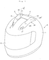
- Figs. 1 to 5 show a helmet according to an embodiment of the present invention.
- a windward side of traveling wind generated during traveling is referred to as the front side
- a leeward side of traveling wind is referred to as the rear side.
- a direction crossing the traveling wind is referred to as the left and right direction.
- the helmet A exemplified in this embodiment includes an impact absorbing liner A1 molded in a predetermined shape using foam polystyrene or a material having the same impact absorbing performance as the foam polystyrene, the impact absorbing liner A1 being mounted on the inside of a helmet body 1 molded in a predetermined shape using fiber-reinforced resin (GFRP, CFRP or the like). Further, the helmet A includes a head-portion interior member (not shown) and a cheek pad (not shown), which are formed of urethane or the like and are arranged on the inside of the inside of the impact absorbing liner A1.
- the helmet body 1 has a shield 2 for opening and closing a front opening portion (not shown) and left and right four ventilation holes 2L, 2R, 2L', and 2R' for discharging hot air within the helmet A.
- a shield 2 for opening and closing a front opening portion (not shown) and left and right four ventilation holes 2L, 2R, 2L', and 2R' for discharging hot air within the helmet A.
- the helmet exemplified in this embodiment is a full face helmet.
- the invention is not limited to the full face helmet, but can be applied to a jet-type helmet or half-type helmet.
- a pair of ventilation covers 3L and 3R for covering the ventilation holes 2L, 2R, 2L', and 2R' are mounted on the surface of the helmet body 1.
- a rectifying body 4 having a rectifying surface 41 is mounted so as to adjust the facing angle of the rectifying surface 41 with respect to traveling wind (refer to Fig. 5 ).
- the rectifying surface 41 rectifies traveling wind while facing the traveling wind acting on the helmet.
- the ventilation covers 3L and 3R are formed of elastic synthetic resin which can be deformed and can be restored from the deformation. Further, the ventilation covers 3L and 3R are formed in a tunnel shape so as to guide traveling wind from the front side to the rear side of the helmet body 1.
- Each of the ventilation covers 3L and 3R has an inlet 31 formed in the front end thereof and an outlet 32 formed in the rear end thereof. By negative pressure generated when traveling wind enters the inlet 31 and then escapes from the outlet 32, hot air within the helmet A is sucked from the ventilation holes 2L, 2R, 2L', and 2R' positioned inside the ventilation covers 3L and 3R so as to be discharged.
- the facing angle adjustment structure is constructed in such a manner that a pair of supporting bodies 5L and 5R fixed to the helmet body 1 support the rectifying body 4.
- the supporting bodies 5L and 5R are formed of the same constituent member. Therefore, in Figs. 3 to 5 , only the supporting body 5L is shown. Further, reference numeral with 'L' will be attached to the respective components associated with the supporting body 5L, and reference numeral with 'R' will be attached to the respective components of the supporting body 5R, which correspond to the respective components of the supporting body 5L.
- the supporting body 5L or 5R is built in the ventilation cover 3L or 3R. Further, the left or right side end portion 42L or 42R of the rectifying body 4 is supported by a fitting projection 61L or 61R which project from a through-hole 31L or 31R opened in a side end portion 30L or 30R of the ventilation cover 3L or 3R.
- the side end portion 42L or 42R of the rectifying body 4 has a fitting concave portion 43L or 43R, into and from which the fitting projection 61L or 61R can be fitted and detached. As the fitting projection 61L or 61R is fitted into the fitting concave portion 43L or 43R, the rectifying body 4 is supported between the ventilation covers 3L and 3R.
- the supporting body 5L or 5R includes a fitting member 6L or 6R having the above-described fitting projection 61L or 61R integrated therewith, and a bearing member 7L or 7R which supports the fitting member 6L or 6R.
- a support portion 8L or 8R and a ratchet mechanism 9L or 9R are provided.
- the support portion 8L or 8R rotatably supports the fitting member 6L or 6R in the same direction as the facing-angle adjustment direction of the rectifying surface 41 in the rectifying body 4, and simultaneously, slidably supports the fitting member 6L or 6R in the front and rear direction.
- the ratchet mechanism 9L or 9R holds the rotational position of the fitting member 6L or 6R, and the holding of the rotational position is released by forward sliding of the fitting member 6L or 6R.
- the facing-angle adjustment direction of the rectifying surface 41 in the rectifying body 4 includes a direction in which the rectifying body 4 is against the airflow of traveling wind, and a direction reverse to the direction against the airflow.
- the rectifying body 4 is supported so as to rotate in both directions.
- the direction against the airflow of traveling wind is referred to as the front direction
- the direction reverse to the direction against the airflow is referred to as the rear direction.
- Reference numerals 10L and 10R represent a slide biasing means which applies a biasing force against the forward sliding of the fitting member 6L or 6R toward the rear side so as to hold the rotational position of the fitting member 6L or 6R with respect to the ratchet mechanism 9L or 9R.
- the slide biasing means 10L or 10R is provided in the bearing member 7L or 7R.
- the fitting member 6L or 6R has a front end formed in a circular arc which is concentric with a rotation orbit, and the fitting projection 61L or 61R is provided to project from the surface of the fitting member 6L or 6R at the rectifying body 4.
- a rotation supporting concave portion 83L or 83R and a rotation guiding concave portion 82L or 82R are provided, which compose one side of the support portion 8L or 8R.
- the rotation supporting concave portion 83L or 83R into which a rotation supporting convex portion 81L or 81R composing the other side of the support portion 8L or 8R is fitted, is formed in the front side of the fitting member 6L or 6R and in an oval shape which is elongated in the front and rear direction.
- the rotation guiding concave portion 82L or 82R into which a rotation guiding convex portion 84L or 84R composing the other side of the support portion 8L or 8R is fitted, is formed in the rear side of the fitting member 6L or 6R.
- the upper side of the rotation guiding concave portion 82L or 82R is opened from the upper end edge toward the lower side thereof, and the length of the rotation guiding concave portion 83L or 83R in the front and rear direction is set to almost the same length as that of the rotation supporting concave portion 83L or 83R in the front and rear direction.
- the fitting member 6L or 6R has a plurality of convex portions 91L or 91R formed in the rear end portion thereof along the vertical direction, the convex portions 91L or 91R composing one side of the ratchet mechanism 9L or 9R.
- Reference numerals 85L and 85R represents a guide plate which guides the rotation of the fitting member 6L or 6R and is held by the bearing member 7L or 7R when the fitting member 6L or 6R rotates or slides in the front and rear direction.
- the bearing member 7L or 7R is integrally provided with a fixing portion 71L or 71R and a bearing portion 72L or 72R.
- the fixing portion 71L or 71R fixes the bearing member 7L or 7R to the helmet body 1 through a fixing screw B, and the bearing portion 72L or 72R supports the fitting member 6L or 6R.
- the fixing portion 71L or 71R is formed of a thin plate with a curved surface which fits into a curved surface of the helmet body 1.
- the fixing screw B is fastened in the front and rear end sides thereof such that the slide biasing means 10L or 10R in the middle of the top surface, the bearing portion 72L or 72R in the rear side of the slide biasing means 10L or 10R, and a plurality of concave portions 92L or 92R in the rear end portion are integrally formed, the concave portion 92L or 92R composing the other side of the ratchet mechanism 9L or 9R.
- the bearing portion 72L or 72R is erected on the edge portion of the fixing portion 71L or 72R at the left or right side end portion 42L or 42R of the rectifying body 4, with the fitting member 6L or 6R interposed therebetween.
- the rotation supporting convex portion 81L or 81R composing the other side of the support portion 8L or 8R is provided to project from a portion of the bearing portion 72L or 72R facing the rotation supporting concave portion 83L or 83R.
- the rotation guiding convex portion 84L or 84R composing the other side of the support portion 8L or 8R is provided to project from a portion of the bearing portion 72L or 72R facing the rotation guiding concave portion 82L or 82R.
- the rotation supporting convex portion 81L or 81R serves as the rotation center of the fitting member 6L or 6R and is formed in a substantially cylindrical shape with a diameter which fits into the vertical width of the rotation supporting concave portion 83L or 83R.
- the rotation guiding convex portion 84L or 84R is moved along the rotation orbit (vertical direction).
- the rotation guiding convex portion 84L or 84R is formed in a substantially square shape.
- the rotation guiding convex portion 84L or 84R has a front and rear width smaller than that of the rotation guiding concave portion 82L or 82R, and the front and rear width is set in such a manner that a space S2 for the forward and rearward sliding of the fitting member 6L or 6R is secured, the space S2 having almost the same width as the front and rear width of the space S1.
- the ratchet mechanism 9L or 9R holds the rotating position of the fitting member 6L or 6R.
- the fitting member 6L or 6R can be rotated.
- the held position (facing angle) of the fitting member 6L or 6R can be changed.
- the convex portion 91L or 91R and the concave portion 92L or 92R are formed in a blade shape such that when the convex portion 91L or 91R and the concave portion 92L or 92R are engaged with each other, the engagement state is maintained against a force which rotates the fitting member 6L or 6R in the rear direction, and the engagement of the convex portion 91L or 91R with the concave portion 92L or 92R can be released with respect to the rotation and sliding of the fitting member 6L or 6R in the front direction (refer to Figs. 4 and 5 ).
- traveling wind acting on the rectifying body 4 serves as a force which rotates the rectifying body 4 in the rear direction and serves to rotate the fitting member 6L or 6R in the rear direction, the fitting member 6L or 6R supporting the rectifying body 4.
- the rotation of the fitting member 6L or 6R in the rear direction is restricted. Therefore, it is possible to prevent the position of the rectifying body 4 from being changed by the traveling wind.
- the slide biasing means 10L or 10R is disposed in the front side of the fitting member 6L or 6R and is formed in a plate spring shape which always comes in contact with the front end portion of the fitting member 6L or 6R.
- the slide biasing means 10L or 10R has a function of applying a biasing force which rearward slides the fitting member 6L or 6R against the forward sliding of the fitting member 6L or 6R.
- the slide biasing means 10L or 10R is pressed against the fitting member 6L or 6R so as to be deformed. Simultaneously, a biasing force is generated, which presses the fitting member 6L or 6R in the rear direction such that the fitting member 6L or 6R is restored.
- the portion of the slide biasing means 10L or 10R, which comes in contact with the front end portion of the fitting member 6L or 6R, is formed in a circular arc which fits into the circular arc of the front end portion.
- the circular arc serves to guide the rotation of the fitting member 6L or 6R.
- the bearing member 7L or 7R is formed of elastic synthetic resin, which can be deformed and restored from the deformation.
- the bearing portion 72L or 72R As a force which expands the bearing portion 72L or 72R in the right and left direction is applied, the bearing portion 72L or 72R is obliquely deformed. Further, as the expanding force is released, the bearing portion 72L or 72R is restored from the oblique deformation such that the fitting concave portion 43L or 43R of the side end portion 42L or 42R in the rectifying body 4 can be engaged with the fitting projection 61L or 61R. In such a manner, a fitting biasing means is constructed.
- slide biasing means 10L or 10R formed of a plate spring, which generates the biasing force, can be formed.
- the side end portion 42R of the rectifying body 4 deforms the side end portion 30R of the ventilation cover 3R in a direction for the supporting body 5R.
- the support portion 72R is pressed toward the right side through the fitting member 6R so as to be obliquely deformed.
- the side end portion 42L of the rectifying body 4 is pulled up and is then moved to the left side such that the fitting concave portion 43R of the right side end portion 42R is removed from the fitting projection 61R. Then, the rectifying body 4 can be detached from the helmet A.
- the attaching can be achieved by performing the detaching operation in the reverse order.
- the supporting body 5L or 5R is built in the ventilation cover 3L or 3R.
- the invention is not limited to this embodiment, but includes an embodiment in which the supporting body 5L or 5R is provided outside the ventilation cover 3L or 3R.
- the slide biasing means 10L or 10R holds the fitting member 6L or 6R in the rear position, and the engagement state between the convex portion 91L or 91R and the concave portion 92L or 92R of the ratchet mechanism 9L or 9R is maintained.
- the engagement between the convex portion 91L or 91R and the concave portion 92L or 92R of the ratchet mechanism 9L or 9R is released by the biasing force of the slide biasing means 10L or 10R. Further, while sliding forward and rearward, the fitting member 6L or 6R is rotated upward. Simultaneously, the rectifying body 4 is forward rotated in accordance with the rotation of the fitting member 6L or 6R.
- the biasing force of the slide biasing means 10L or 10R acts on the fitting member 6L or 6R. Therefore, when the force which rotates the rectifying body 4 upward is released, the concave portion 91L or 91R of the ratchet mechanism 9L or 9R is inevitably restored to the engagement state with respect to the concave portion 92L or 92R. Then, the facing angle of the rectifying body 4 is maintained.
- a force is applied to forward slide the rectifying body 4 from the facing angle holding state of the rectifying body 4. Then, in accordance with the sliding, the fitting member 6L or 6R is forward slid against the biasing force of the slide biasing means 10L or 10R, and the engagement between the concave portion 91L or 91R and the convex portion 92L or 92R of the ratchet mechanism 9L or 9R is released. Then, the rectifying body 4 can be rotated in the rear direction in a state where the rectifying body 4 is forward slid.
- the facing angle of the rectifying body 4 can be arbitrarily adjusted. Further, the rearward rotation of the rectifying body 4 during traveling is prevented by the engagement between the convex portion 91L or 91R and the concave portion 92L or 92R of the ratchet mechanism 9L or 9R. Therefore, although traveling wind acts as a force which rotates the rectifying body 4 in the rearward direction, the angle of the rectifying body 4 is not changed, and the set facing angle can be reliably maintained.
- the rearward rotation of the rectifying body 4 can performed by only the above-described artificial operation with respect to the rectifying body 4.
- the rectifying body 4 In the engagement state between the convex portion 91L or 91R and the concave portion 92L or 92R of the ratchet mechanism 9L or 9R, although an artificial force which rotates the rectifying body 4 in the rear direction is applied, the rectifying body 4 is not rotated. Therefore, although a wearer of the helmet A inadvertently applies an artificial force which rotates the rectifying body 4 in the rear direction, the angle of the rectifying body 4 is not changed, and the set facing angle can be reliably maintained.
- the respective components composing the facing angle adjustment structure of the rectifying body 4 are not seen from the outside of the helmet A. Therefore, the design of the helmet A can be enhanced.
Landscapes
- Physics & Mathematics (AREA)
- Fluid Mechanics (AREA)
- Helmets And Other Head Coverings (AREA)
Abstract
A facing angle of a rectifying surface in a rectifying body 4 is adjusted in a multistage manner, and the adjusted facing angle is maintained.
Description
- The present invention relates to a helmet which is worn to rides on various vehicles, such as a motor cycle, a four-wheel car, a motor boat, a bicycle and so on, and more specifically, to a helmet which has a ventilation structure which ventilates hot air within the helmet and a rectifying structure for separating traveling wind from the surface of the helmet.
- As information on a prior-art document related to the present invention, there is provided
Patent Document 1, for example. - [Patent Document 1] Japanese Unexamined Patent Application Publication No.
2006-299456 -
Patent Document 1 discloses a helmet which includes a rectifying body which separates traveling wind from the surface of the helmet. The rectifying body is provided so as to adjust the angle of a rectifying surface facing the traveling wind in response to unique driving postures of a person wearing the helmet or the speed of a transportation means. - In the helmet disclosed in
Patent Document 1, regardless of a difference in unique driving posture of a helmet wearer or speed of a transportation means, the separation of traveling wind is performed, thereby enhancing a ventilation operation and rectifying operation. However, the present applicant has devoted himself to studies for securing the ease of angle change operation while enhancing the reliability of angle maintenance of the rectifying body in the rectifying structure. As a result, the present application has invented the present invention. - In order to achieve the above-mentioned object, an advantage of the present invention is that it provides a helmet which has a function of separating traveling wind while enhancing the reliability of angle maintenance of a rectifying body in a rectifying structure, regardless of a difference in unique driving posture of a helmet wearer or speed of a transportation means and can secure the ease of angle change operation.
- According to one aspect of the invention there is provided a helmet with a rectifying body provided on the surface of the helmet body, the rectifying body being involved in maintaining stability of the helmet against airflow when worn during travelling,
wherein the angle of a rectifying surface of the rectifying body facing the travelling wind can be adjusted in response to the driving postures of a helmet wearer and/or the speed of a transportation means,
the rectifying body is supported so as to be rotatable in a first direction against an airflow of travelling wind and in a reverse direction against the airflow and is supported so as to be slidable from the windward side of the travelling wind to the leeward side thereof,
a bearing member is provided which rotatably and slidably supports the rectifying body; a slide biasing means applies a windward biasing force to the rectifying body; and a ratchet mechanism adjusts the facing angle of the rectifying surface in a multistage manner and maintains the facing angle, and
when the rectifying body is located at the end on the leeward side in the sliding direction, the ratchet mechanism maintains a facing angle holding state of the rectifying surface and the facing angle holding state is released by sliding the rectifying body in the windward direction. - In one embodiment the rectifying body is supported by a supporting body.
- According to another aspect of the invention, a helmet includes a rectifying body provided on the surface of a helmet body, the rectifying body being involved in maintaining stability of the helmet against airflow during traveling. The angle of a rectifying surface of the rectifying body facing traveling wind can be adjusted in response to unique driving postures of a helmet wearer or the speed of a transportation means. The rectifying body is supported through a pair of supporting bodies facing a direction crossing the traveling direction so as to be rotatable in a direction against an airflow of traveling wind and in a direction reverse to the direction against the airflow and is supported so as to be slidable to the windward side of the traveling wind and the leeward side thereof. The supporting body includes a bearing member which rotatably and slidably supports the rectifying body; a slide biasing means which applies a windward biasing force to the rectifying body; and a ratchet mechanism which adjusts the facing angle of the rectifying surface in a multistage manner and maintains the facing angle. When the rectifying body is located at the end on the leeward side in the sliding direction, the ratchet mechanism maintains a facing angle holding state in the rectifying surface against a force which rotates the rectifying body in a direction reverse to the direction against the airflow of the traveling wind, and the facing angle holding state is released by sliding the rectifying body in the windward direction.
- In whichever aspect, typically the supporting body is integrally provided with a fitting member having a fitting projection which can be fitted into and detached from a side end portion of the rectifying body in a direction crossing the traveling wind direction; and a fitting biasing means which applies a biasing force against a force in a direction crossing the traveling wind direction and in a direction away from a side end portion of the rectifying body to the fitting member. The fitting member is supported by the bearing member so as to be rotatable in accordance with the rotation of the rectifying body and to be slidable in accordance with the sliding of the rectifying body.
- The ratchet member is provided across the fitting member and the bearing member.
- The rectifying body is disposed to extend between two ventilation covers parallel to a traveling direction.
- Further, the rectifying body is disposed to extend between two ventilation covers parallel to a traveling direction, and the supporting body is disposed in each of the ventilation covers. A through-hole through which the fitting projection passes is formed in a side end portion of the ventilation cover facing the side end portion of the rectifying body such that the fitting projection passing through the through-hole is fitted into the side end portion of the rectifying body.
- That is, the support member (including the ratchet mechanism and so on) supporting the rectifying body and the adjustment mechanism which adjusts the facing angle of the rectifying surface in the rectifying body are constructed so as not to be exposed to the outside of the ventilation cover. Therefore, the design of the helmet can be enhanced. Further, since traveling wind does not act on the support member or the adjustment mechanism, wind noise can be reduced.
- In the present invention, the following excellent effects can be expected through the above-described construction.
- It is possible to provide a helmet which has a function of separating traveling wind while enhancing the reliability of angle maintenance of a rectifying body in a rectifying structure and can secure the ease of angle change operation of the rectifying body regardless of a difference in unique driving posture of a helmet wearer or speed of a transportation means.
-
-
Fig. 1 is a perspective view of a helmet according to the present invention. -
Fig. 2 is an expanded plan view ofFig. 2 . -
Fig. 3 is an expanded view of essential parts of the helmet. -
Fig. 4 is a cross-sectional view of line (IV) - (IV) ofFig. 3 . -
Fig. 5 is a cross-sectional view of line (V) - (V) ofFig. 3 . - Hereinafter, a helmet according to an embodiment of the present embodiment will be described with reference to the accompanying drawings.
-
Figs. 1 to 5 show a helmet according to an embodiment of the present invention. - In this embodiment, a windward side of traveling wind generated during traveling is referred to as the front side, and a leeward side of traveling wind is referred to as the rear side.
- Further, a direction crossing the traveling wind is referred to as the left and right direction.
- The helmet A exemplified in this embodiment includes an impact absorbing liner A1 molded in a predetermined shape using foam polystyrene or a material having the same impact absorbing performance as the foam polystyrene, the impact absorbing liner A1 being mounted on the inside of a
helmet body 1 molded in a predetermined shape using fiber-reinforced resin (GFRP, CFRP or the like). Further, the helmet A includes a head-portion interior member (not shown) and a cheek pad (not shown), which are formed of urethane or the like and are arranged on the inside of the inside of the impact absorbing liner A1. Thehelmet body 1 has ashield 2 for opening and closing a front opening portion (not shown) and left and right fourventilation holes - The helmet exemplified in this embodiment is a full face helmet. However, the invention is not limited to the full face helmet, but can be applied to a jet-type helmet or half-type helmet.
- In the helmet A according to this embodiment, a pair of ventilation covers 3L and 3R for covering the
ventilation holes helmet body 1. Between the ventilation covers 3L and 3R, a rectifyingbody 4 having a rectifyingsurface 41 is mounted so as to adjust the facing angle of the rectifyingsurface 41 with respect to traveling wind (refer toFig. 5 ). The rectifyingsurface 41 rectifies traveling wind while facing the traveling wind acting on the helmet. - The ventilation covers 3L and 3R are formed of elastic synthetic resin which can be deformed and can be restored from the deformation. Further, the ventilation covers 3L and 3R are formed in a tunnel shape so as to guide traveling wind from the front side to the rear side of the
helmet body 1. Each of the ventilation covers 3L and 3R has aninlet 31 formed in the front end thereof and anoutlet 32 formed in the rear end thereof. By negative pressure generated when traveling wind enters theinlet 31 and then escapes from theoutlet 32, hot air within the helmet A is sucked from theventilation holes - Hereinafter, the facing angle adjustment structure of the rectifying
body 4 in the helmet A according to this embodiment will be described with reference toFigs. 2 to 5 . - The facing angle adjustment structure is constructed in such a manner that a pair of supporting
bodies helmet body 1 support the rectifyingbody 4. - The supporting
bodies Figs. 3 to 5 , only the supportingbody 5L is shown. Further, reference numeral with 'L' will be attached to the respective components associated with the supportingbody 5L, and reference numeral with 'R' will be attached to the respective components of the supportingbody 5R, which correspond to the respective components of the supportingbody 5L. - The supporting
body ventilation cover side end portion body 4 is supported by afitting projection hole side end portion ventilation cover - The
side end portion body 4 has a fittingconcave portion fitting projection fitting projection concave portion body 4 is supported between the ventilation covers 3L and 3R. - More specifically, the supporting
body fitting member fitting projection member fitting member - Across the
fitting member member support portion ratchet mechanism support portion fitting member surface 41 in the rectifyingbody 4, and simultaneously, slidably supports thefitting member ratchet mechanism fitting member fitting member - Here, the facing-angle adjustment direction of the rectifying
surface 41 in the rectifyingbody 4 includes a direction in which the rectifyingbody 4 is against the airflow of traveling wind, and a direction reverse to the direction against the airflow. The rectifyingbody 4 is supported so as to rotate in both directions. - Hereinafter, the direction against the airflow of traveling wind is referred to as the front direction, and the direction reverse to the direction against the airflow is referred to as the rear direction.
-
Reference numerals fitting member fitting member ratchet mechanism member - In
Figs. 4 and5 , thefitting member fitting projection fitting member body 4. On the surface of thefitting member fitting projection concave portion concave portion support portion - The rotation supporting
concave portion convex portion support portion fitting member - Further, the rotation guiding
concave portion convex portion support portion fitting member concave portion concave portion concave portion - The
fitting member convex portions convex portions ratchet mechanism -
Reference numerals fitting member member fitting member - The bearing
member portion portion portion member helmet body 1 through a fixing screw B, and the bearingportion fitting member - The fixing
portion helmet body 1. The fixing screw B is fastened in the front and rear end sides thereof such that the slide biasing means 10L or 10R in the middle of the top surface, the bearingportion concave portions concave portion ratchet mechanism - The bearing
portion portion side end portion body 4, with thefitting member - The rotation supporting
convex portion support portion portion concave portion convex portion support portion portion concave portion - The rotation supporting
convex portion fitting member concave portion - That is, when the rotation supporting
convex portion concave portion fitting member concave portion - As the
fitting member concave portion convex portion convex portion - The rotation guiding
convex portion concave portion fitting member - As the
convex portions concave portions ratchet mechanism fitting member convex portion concave portion fitting member - As the engagement position of the
convex portion concave portion fitting member - The
convex portion concave portion convex portion concave portion fitting member convex portion concave portion fitting member Figs. 4 and5 ). - According to the
ratchet mechanism body 4 serves as a force which rotates the rectifyingbody 4 in the rear direction and serves to rotate thefitting member fitting member body 4. At this time, however, as the engagement of theconvex portion concave portion fitting member body 4 from being changed by the traveling wind. - Adversely, when an artificial force which rotates the rectifying
body 4 in the front direction is applied, this force acts so as to rotate thefitting member convex portion concave portion body 4 can be rotated in the front direction. - Further, when an artificial force which slides the rectifying
body 4 in the front direction is applied, the engagement of theconvex portion concave portion body 4 can be rotated in the front and rear direction. - The slide biasing means 10L or 10R is disposed in the front side of the
fitting member fitting member fitting member fitting member - That is, as the slide biasing means 10L or 10R holds the
fitting member convex portion concave portion ratchet mechanism - Further, with the forward sliding of the
fitting member fitting member fitting member fitting member - The portion of the slide biasing means 10L or 10R, which comes in contact with the front end portion of the
fitting member fitting member - The bearing
member - According to the bearing
member portion portion portion concave portion side end portion body 4 can be engaged with thefitting projection - Further, the slide biasing means 10L or 10R formed of a plate spring, which generates the biasing force, can be formed.
- That is, as the rectifying
body 4 is pressed toward the left side ofFig. 3 , theside end portion 42R of the rectifyingbody 4 deforms theside end portion 30R of theventilation cover 3R in a direction for the supportingbody 5R. As theside end portion 30R is deformed, thesupport portion 72R is pressed toward the right side through thefitting member 6R so as to be obliquely deformed. - At this time, since the
side end portion 42L of the rectifyingbody 4 is also moved to the right side, the fittingconcave portion 43L of theside end portion 42L is detached from thefitting projection 61L of thefitting member 6L. - In this state, the
side end portion 42L of the rectifyingbody 4 is pulled up and is then moved to the left side such that the fittingconcave portion 43R of the rightside end portion 42R is removed from thefitting projection 61R. Then, the rectifyingbody 4 can be detached from the helmet A. - When the rectifying
body 4 is detached, the bearingportion 72R is restored to the original shape from the deformation by the biasing force of the fitting biasing means. - When the rectifying
body 4 is attached to the helmet A, the attaching can be achieved by performing the detaching operation in the reverse order. - In this embodiment, it has been exemplified that the supporting
body ventilation cover body ventilation cover - Hereinafter, the facing angle adjustment operation of the rectifying
body 4 of the helmet A according to this embodiment will be described. - In an facing angle holding state of the rectifying
body 4, the slide biasing means 10L or 10R holds thefitting member convex portion concave portion ratchet mechanism - Further, as a force in a direction which forward rotates the rectifying
body 4 from the facing angle holding state is applied, the engagement between theconvex portion concave portion ratchet mechanism fitting member body 4 is forward rotated in accordance with the rotation of thefitting member - In the forward rotation of the rectifying
body 4, the biasing force of the slide biasing means 10L or 10R acts on thefitting member body 4 upward is released, theconcave portion ratchet mechanism concave portion body 4 is maintained. - Further, a force is applied to forward slide the rectifying
body 4 from the facing angle holding state of the rectifyingbody 4. Then, in accordance with the sliding, thefitting member concave portion convex portion ratchet mechanism body 4 can be rotated in the rear direction in a state where the rectifyingbody 4 is forward slid. - Further, in a state where the rectifying
body 4 is rotated to a target position, the force applied to the rectifyingbody 4 in the sliding direction is released. Then, thefitting member convex portion ratchet mechanism concave portion body 4 is maintained. - According to the facing angle adjustment structure of the rectifying
body 4, the facing angle of the rectifyingbody 4 can be arbitrarily adjusted. Further, the rearward rotation of the rectifyingbody 4 during traveling is prevented by the engagement between theconvex portion concave portion ratchet mechanism body 4 in the rearward direction, the angle of the rectifyingbody 4 is not changed, and the set facing angle can be reliably maintained. - Further, the rearward rotation of the rectifying
body 4 can performed by only the above-described artificial operation with respect to the rectifyingbody 4. In the engagement state between theconvex portion concave portion ratchet mechanism body 4 in the rear direction is applied, the rectifyingbody 4 is not rotated. Therefore, although a wearer of the helmet A inadvertently applies an artificial force which rotates the rectifyingbody 4 in the rear direction, the angle of the rectifyingbody 4 is not changed, and the set facing angle can be reliably maintained. - As described above, since only the rectifying
body 4 can be attached and detached, an exchange operation of the rectifyingbody 4 can be performed easily. - As the supporting
body ventilation cover body 4 are not seen from the outside of the helmet A. Therefore, the design of the helmet A can be enhanced. - While the present invention has been described with reference to exemplary embodiments thereof, it will be understood by those skilled in the art that various changes and modifications in form and detail may be made therein without departing from the scope of the present invention as defined by the following claims.
-
- A:
- HELMET
- 1:
- HELMET BODY
- 2L:
- VENTILATION HOLE
- 2R:
- VENTILATION HOLE
- 2L':
- VENTILATION HOLE
- 2R':
- VENTILATION HOLE
- 3L:
- VENTILATION COVER
- 3R:
- VENTILATION COVER
- 30L:
- SIDE END PORTION
- 30R:
- SIDE END PORTION
- 31L:
- THROUGH-HOLE
- 31R:
- THROUGH-HOLE
- 4:
- RECTIFYING BODY
- 41:
- RECTIFYING SURFACE
- 42L:
- SIDE END PORTION
- 42R:
- SIDE END PORTION
- 43L:
- FITTING CONCAVE PORTION
- 43R:
- FITTING CONCAVE PORTION
- 5L:
- SUPPORTING BODY
- 5R:
- SUPPORTING BODY
- 6L:
- FITTING MEMBER
- 6R:
- FITTING MEMBER
- 61L:
- FITTING PROJECTION
- 61R:
- FITTING PROJECTION
- 7L:
- SUPPORT MEMBER
- 7R:
- SUPPORT MEMBER
- 81L:
- ROTATION SUPPORTING CONVEX PORTION
- 81R:
- ROTATION SUPPORTING CONVEX PORTION
- 83L:
- ROTATION SUPPORTING CONCAVE PORTION
- 83R:
- ROTATION SUPPORTING CONCAVE PORTION
- 9L:
- RATCHET MECHANISM
- 9R:
- RATCHET MECHANISM
- 91L:
- CONVEX PORTION
- 91R:
- CONVEX PORTION
- 92L:
- CONCAVE PORTION
- 92R:
- CONCAVE PORTION
- 10L:
- SLIDE BIASING MEANS
- 10R:
- SLIDE BIASING MEANS
- S1:
- SPACE
- S2:
- SPACE
Claims (8)
- A helmet with a rectifying body provided on the surface of the helmet body, the rectifying body being involved in maintaining stability of the helmet against airflow when worn during travelling,
wherein the angle of a rectifying surface of the rectifying body facing the travelling wind can be adjusted in response to the driving postures of a helmet wearer and/or the speed of a transportation means,
the rectifying body is supported so as to be rotatable in a first direction against an airflow of travelling wind and in a reverse direction against the airflow and is supported so as to be slidable from the windward side of the travelling wind to the leeward side thereof,
a bearing member is provided which rotatably and slidably supports the rectifying body; a slide biasing means applies a windward biasing force to the rectifying body; and a ratchet mechanism adjusts the facing angle of the rectifying surface in a multistage manner and maintains the facing angle, and
when the rectifying body is located at the end on the leeward side in the sliding direction, the ratchet mechanism maintains a facing angle holding state of the rectifying surface and the facing angle holding state is released by sliding the rectifying body in the windward direction. - The helmet according to claim 1 wherein the rectifying body is supported by a supporting body.
- The helmet according to Claim 2 wherein the supporting body is integrally provided with a fitting member having a fitting projection which can be fitted into and detached from a side end portion of the rectifying body in a direction crossing the travelling wind direction; and a fitting biasing means which applies a biasing force against a force in a direction crossing the travelling wind direction and in a direction away from a side end portion of the rectifying body to the fitting member, and
the fitting member is supported by the bearing member so as to be rotatable in accordance with the rotation of the rectifying body and to be slidable in accordance with the sliding of the rectifying body. - The helmet according to claim 3 wherein the ratchet member is provided across the fitting member and the bearing member.
- The helmet according to claim 2 wherein the support is formed by a pair of supporting bodies facing a direction crossing the travelling direction.
- The helmet according to any one of claims 1 to 5 wherein the rectifying body is disposed to extend between two ventilation covers parallel to a travelling direction.
- The helmet according to any one of claims 1 to 6, wherein the rectifying body is disposed to extend between two ventilation covers parallel to a travelling direction, the supporting body is disposed in each of the ventilation covers, and
a through-hole through which the fitting projection passes is formed in a side end portion of the ventilation cover facing the side end portion of the rectifying body such that the fitting projection passing through the through-hole is fitted into the side end portion of the rectifying body. - A helmet comprising a rectifying body provided on the surface of a helmet body, the rectifying body being involved in maintaining stability of the helmet against airflow during travelling,
wherein the angle of a rectifying surface of the rectifying body facing travelling wind can be adjusted in response to unique driving postures of a helmet wearer or the speed of a transportation means,
the rectifying body is supported through a pair of supporting bodies facing a direction crossing the travelling direction so as to be rotatable in a direction against an airflow of travelling wind and in a direction reverse to the direction against the airflow and is supported so as to be slidable from the windward side of the travelling wind to the leeward side thereof,
the supporting body includes a bearing member which rotatable and slidably supports the rectifying body; a slide biasing means applies a windward biasing force to the rectifying body; and a ratchet mechanism which adjusts the facing angle of the rectifying surface in a multistage manner and maintains the facing angle, and
when the rectifying body is located at the end on the leeward side in the sliding direction, the ratchet mechanism maintains a facing angle holding state in the rectifying surface against a force which rotates the rectifying body, in a direction reverse to the direction against the airflow of the travelling wind, and the facing angle holding state is released by sliding the rectifying body in the windward direction.
Applications Claiming Priority (1)
| Application Number | Priority Date | Filing Date | Title |
|---|---|---|---|
| JP2007260936A JP4533922B2 (en) | 2007-10-04 | 2007-10-04 | helmet |
Publications (3)
| Publication Number | Publication Date |
|---|---|
| EP2044854A2 true EP2044854A2 (en) | 2009-04-08 |
| EP2044854A3 EP2044854A3 (en) | 2009-11-04 |
| EP2044854B1 EP2044854B1 (en) | 2011-04-20 |
Family
ID=40032484
Family Applications (1)
| Application Number | Title | Priority Date | Filing Date |
|---|---|---|---|
| EP08250890A Not-in-force EP2044854B1 (en) | 2007-10-04 | 2008-03-14 | Helmet |
Country Status (8)
| Country | Link |
|---|---|
| US (1) | US7748059B2 (en) |
| EP (1) | EP2044854B1 (en) |
| JP (1) | JP4533922B2 (en) |
| KR (1) | KR101345169B1 (en) |
| CN (1) | CN101401668B (en) |
| AT (1) | ATE505964T1 (en) |
| DE (1) | DE602008006321D1 (en) |
| TW (1) | TWI402043B (en) |
Cited By (1)
| Publication number | Priority date | Publication date | Assignee | Title |
|---|---|---|---|---|
| WO2017032577A1 (en) * | 2015-08-27 | 2017-03-02 | Bayerische Motoren Werke Aktiengesellschaft | Safety helmet with an aerodynamic stabilizing element |
Families Citing this family (14)
| Publication number | Priority date | Publication date | Assignee | Title |
|---|---|---|---|---|
| USD597259S1 (en) * | 2008-07-14 | 2009-07-28 | Gentex Corporation | Roll bar portion of a helmet |
| US11324273B2 (en) | 2011-02-09 | 2022-05-10 | 6D Helmets, Llc | Omnidirectional energy management systems and methods |
| US10561192B2 (en) | 2011-02-09 | 2020-02-18 | 6D Helmets, Llc | Omnidirectional energy management systems and methods |
| US12336585B2 (en) | 2011-02-09 | 2025-06-24 | 6D Helmets, Llc | Omnidirectional energy management systems and methods |
| US11766085B2 (en) | 2011-02-09 | 2023-09-26 | 6D Helmets, Llc | Omnidirectional energy management systems and methods |
| CN103635112B (en) | 2011-02-09 | 2015-12-23 | 6D头盔有限责任公司 | Helmet omnidirectional EMS |
| ITMI20111487A1 (en) * | 2011-08-03 | 2013-02-04 | Opticos Srl | PROTECTIVE HELMET EQUIPPED WITH VENTILATION |
| JP2015098660A (en) * | 2013-11-19 | 2015-05-28 | 株式会社アライヘルメット | Helmet |
| US9975032B2 (en) * | 2014-03-24 | 2018-05-22 | Mark Frey | Concussive helmet |
| US9918509B2 (en) * | 2016-07-08 | 2018-03-20 | Juan Moreno | Ventilated helmet assembly |
| JP2020023774A (en) * | 2018-07-31 | 2020-02-13 | 株式会社オージーケーカブト | Helmet |
| JP7017532B2 (en) * | 2019-02-22 | 2022-02-08 | 株式会社Shoei | Airflow control member for helmet and helmet |
| FR3125685B1 (en) * | 2021-07-30 | 2024-05-31 | Shark | Protective helmet with optimized aerodynamic deflector |
| JP7762547B2 (en) * | 2021-11-17 | 2025-10-30 | 株式会社Shoei | helmet |
Citations (1)
| Publication number | Priority date | Publication date | Assignee | Title |
|---|---|---|---|---|
| JP2006299456A (en) | 2005-04-20 | 2006-11-02 | Arai Helmet Ltd | Helmet |
Family Cites Families (26)
| Publication number | Priority date | Publication date | Assignee | Title |
|---|---|---|---|---|
| JPH0437859Y2 (en) * | 1987-08-26 | 1992-09-04 | ||
| IT1223434B (en) * | 1987-12-15 | 1990-09-19 | Nolan Spa | PROTECTIVE HELMET FOR MOTORCYCLISTS AND SIMILAR EQUIPPED WITH VENTILATION VEHICLES, MANUALLY ADJUSTABLE |
| JPH0350720U (en) * | 1989-09-22 | 1991-05-17 | ||
| JPH06406Y2 (en) | 1989-11-07 | 1994-01-05 | 理夫 新井 | Helmet ventilation system |
| IT220163Z2 (en) * | 1990-09-19 | 1993-06-24 | Nava Pierluigi | FULL-FACE HELMET FOR MOTORCYCLE EQUIPPED WITH MEANS TO PREVENT THE FOGING OF THE VISOR OF THE SAME. |
| JPH0635684B2 (en) * | 1990-10-03 | 1994-05-11 | 昭栄化工株式会社 | Riding helmet |
| US5533500A (en) * | 1992-03-04 | 1996-07-09 | Her-Mou; Lin | Helmet with an air filtering device |
| JPH06102844B2 (en) | 1992-12-07 | 1994-12-14 | 昭栄化工株式会社 | Ventilation device for riding helmet |
| IT230468Y1 (en) * | 1993-10-13 | 1999-06-07 | Carlo Lamattina | HELMET FOR MOTORCYCLISTS EQUIPPED WITH ADJUSTABLE REAR AERODYNAMIC STABILIZER |
| JP2610795B2 (en) | 1995-04-20 | 1997-05-14 | 株式会社アライヘルメット | Helmet ventilation |
| DE19628087A1 (en) | 1996-07-12 | 1998-01-15 | Bayerische Motoren Werke Ag | Protective helmet with ventilation device |
| JP3675976B2 (en) * | 1996-07-30 | 2005-07-27 | 株式会社Shoei | helmet |
| US5855404A (en) * | 1996-11-25 | 1999-01-05 | Saunders; Charles A. | Motorcycle windshield fairing |
| JP3934727B2 (en) * | 1997-02-28 | 2007-06-20 | 株式会社Shoei | helmet |
| JP3050720U (en) * | 1998-01-19 | 1998-07-31 | オージーケー販売株式会社 | Rear rectifier for helmet and helmet with rear rectifier |
| KR200201724Y1 (en) | 1998-04-09 | 2000-11-01 | 박수안 | Rear spoiler for helmet |
| US5996128A (en) * | 1998-12-31 | 1999-12-07 | Korea Ogk Co., Ltd. | Air flow adjusting rear member of the helmet |
| JP3046820B1 (en) * | 1999-05-25 | 2000-05-29 | オージーケー販売株式会社 | Helmet having ventilation function and shutter device for ventilation |
| US6061834A (en) * | 1999-06-14 | 2000-05-16 | Liao; Cheng-An | Air ventilation safety helmet |
| US6347412B1 (en) * | 2000-10-23 | 2002-02-19 | Mark Dorman | Sound reflector for a bicyclist |
| EP1396200B1 (en) * | 2001-06-12 | 2006-12-06 | Shoei Co., Ltd. | Helmet |
| US6973676B1 (en) * | 2003-09-02 | 2005-12-13 | Elwood Jesse Bill Simpson | Protective helmet with integral air supply |
| US20050066416A1 (en) * | 2003-09-29 | 2005-03-31 | Chang-Ching Ma | Air-flow control valve device for a helmet |
| JP4848155B2 (en) * | 2005-08-19 | 2011-12-28 | 株式会社Shoei | helmet |
| KR100661967B1 (en) * | 2006-02-01 | 2006-12-28 | 주식회사 제이텍 | Combination structure of helmet vent |
| JP4125761B2 (en) * | 2006-04-10 | 2008-07-30 | 株式会社アライヘルメット | helmet |
-
2007
- 2007-10-04 JP JP2007260936A patent/JP4533922B2/en not_active Expired - Fee Related
- 2007-10-31 TW TW096140901A patent/TWI402043B/en not_active IP Right Cessation
- 2007-11-20 KR KR1020070118547A patent/KR101345169B1/en not_active Expired - Fee Related
- 2007-12-28 CN CN2007103004682A patent/CN101401668B/en not_active Expired - Fee Related
-
2008
- 2008-01-24 US US12/010,365 patent/US7748059B2/en not_active Expired - Fee Related
- 2008-03-14 EP EP08250890A patent/EP2044854B1/en not_active Not-in-force
- 2008-03-14 AT AT08250890T patent/ATE505964T1/en not_active IP Right Cessation
- 2008-03-14 DE DE602008006321T patent/DE602008006321D1/en active Active
Patent Citations (1)
| Publication number | Priority date | Publication date | Assignee | Title |
|---|---|---|---|---|
| JP2006299456A (en) | 2005-04-20 | 2006-11-02 | Arai Helmet Ltd | Helmet |
Cited By (3)
| Publication number | Priority date | Publication date | Assignee | Title |
|---|---|---|---|---|
| WO2017032577A1 (en) * | 2015-08-27 | 2017-03-02 | Bayerische Motoren Werke Aktiengesellschaft | Safety helmet with an aerodynamic stabilizing element |
| DE102015216436A1 (en) | 2015-08-27 | 2017-03-02 | Bayerische Motoren Werke Aktiengesellschaft | Hard hat with aerodynamic stabilization element |
| US11166509B2 (en) | 2015-08-27 | 2021-11-09 | Bayerische Motoren Werke Aktiengesellschaft | Safety helmet with an aerodynamic stabilizing element |
Also Published As
| Publication number | Publication date |
|---|---|
| KR101345169B1 (en) | 2013-12-26 |
| TW200916010A (en) | 2009-04-16 |
| EP2044854A3 (en) | 2009-11-04 |
| US7748059B2 (en) | 2010-07-06 |
| CN101401668B (en) | 2011-06-08 |
| KR20090034693A (en) | 2009-04-08 |
| CN101401668A (en) | 2009-04-08 |
| EP2044854B1 (en) | 2011-04-20 |
| HK1127980A1 (en) | 2009-10-16 |
| TWI402043B (en) | 2013-07-21 |
| JP2009091675A (en) | 2009-04-30 |
| US20090089918A1 (en) | 2009-04-09 |
| JP4533922B2 (en) | 2010-09-01 |
| DE602008006321D1 (en) | 2011-06-01 |
| ATE505964T1 (en) | 2011-05-15 |
Similar Documents
| Publication | Publication Date | Title |
|---|---|---|
| EP2044854B1 (en) | Helmet | |
| JP2006299456A (en) | Helmet | |
| EP1743538B1 (en) | Full-face-type helmet | |
| EP0474939B1 (en) | Helmet | |
| US5361419A (en) | Helmet with sound ducts | |
| JPH04126813A (en) | Driving helmet | |
| JP5215079B2 (en) | Helmet with shield | |
| EP1844671B1 (en) | Ventilation arrangement for a helmet | |
| TWI253331B (en) | Supporting structure of chin-ventilation shutter for full-face type helmet | |
| DE60109878D1 (en) | Riding helmet with ventilation device | |
| US20090303430A1 (en) | Wind powered sport goggles | |
| HK1127980B (en) | Helmet | |
| ES3035536T3 (en) | Protective helmet with an optimised aerodynamic deflector | |
| JP4374489B2 (en) | helmet | |
| JP2015098660A (en) | Helmet | |
| US8876199B2 (en) | Sunshade apparatus | |
| JP2019085663A (en) | helmet | |
| JPH0466925B2 (en) | ||
| JPH0216971Y2 (en) | ||
| JP2005325461A (en) | Full face helmet |
Legal Events
| Date | Code | Title | Description |
|---|---|---|---|
| PUAI | Public reference made under article 153(3) epc to a published international application that has entered the european phase |
Free format text: ORIGINAL CODE: 0009012 |
|
| AK | Designated contracting states |
Kind code of ref document: A2 Designated state(s): AT BE BG CH CY CZ DE DK EE ES FI FR GB GR HR HU IE IS IT LI LT LU LV MC MT NL NO PL PT RO SE SI SK TR |
|
| AX | Request for extension of the european patent |
Extension state: AL BA MK RS |
|
| PUAL | Search report despatched |
Free format text: ORIGINAL CODE: 0009013 |
|
| AK | Designated contracting states |
Kind code of ref document: A3 Designated state(s): AT BE BG CH CY CZ DE DK EE ES FI FR GB GR HR HU IE IS IT LI LT LU LV MC MT NL NO PL PT RO SE SI SK TR |
|
| AX | Request for extension of the european patent |
Extension state: AL BA MK RS |
|
| RIC1 | Information provided on ipc code assigned before grant |
Ipc: A42B 3/04 20060101AFI20090930BHEP Ipc: A42B 3/28 20060101ALI20090930BHEP |
|
| 17P | Request for examination filed |
Effective date: 20091217 |
|
| 17Q | First examination report despatched |
Effective date: 20100426 |
|
| AKX | Designation fees paid |
Designated state(s): AT BE BG CH CY CZ DE DK EE ES FI FR GB GR HR HU IE IS IT LI LT LU LV MC MT NL NO PL PT RO SE SI SK TR |
|
| GRAP | Despatch of communication of intention to grant a patent |
Free format text: ORIGINAL CODE: EPIDOSNIGR1 |
|
| RIC1 | Information provided on ipc code assigned before grant |
Ipc: A42B 3/28 20060101ALI20101202BHEP Ipc: A42B 3/04 20060101AFI20101202BHEP |
|
| GRAS | Grant fee paid |
Free format text: ORIGINAL CODE: EPIDOSNIGR3 |
|
| GRAA | (expected) grant |
Free format text: ORIGINAL CODE: 0009210 |
|
| AK | Designated contracting states |
Kind code of ref document: B1 Designated state(s): AT BE BG CH CY CZ DE DK EE ES FI FR GB GR HR HU IE IS IT LI LT LU LV MC MT NL NO PL PT RO SE SI SK TR |
|
| REG | Reference to a national code |
Ref country code: GB Ref legal event code: FG4D |
|
| REG | Reference to a national code |
Ref country code: CH Ref legal event code: EP Ref country code: CH Ref legal event code: NV Representative=s name: ABREMA AGENCE BREVET ET MARQUES, GANGUILLET |
|
| REG | Reference to a national code |
Ref country code: IE Ref legal event code: FG4D |
|
| REF | Corresponds to: |
Ref document number: 602008006321 Country of ref document: DE Date of ref document: 20110601 Kind code of ref document: P |
|
| REG | Reference to a national code |
Ref country code: DE Ref legal event code: R096 Ref document number: 602008006321 Country of ref document: DE Effective date: 20110601 |
|
| REG | Reference to a national code |
Ref country code: NL Ref legal event code: T3 |
|
| REG | Reference to a national code |
Ref country code: SE Ref legal event code: TRGR |
|
| LTIE | Lt: invalidation of european patent or patent extension |
Effective date: 20110420 |
|
| PG25 | Lapsed in a contracting state [announced via postgrant information from national office to epo] |
Ref country code: LT Free format text: LAPSE BECAUSE OF FAILURE TO SUBMIT A TRANSLATION OF THE DESCRIPTION OR TO PAY THE FEE WITHIN THE PRESCRIBED TIME-LIMIT Effective date: 20110420 Ref country code: PT Free format text: LAPSE BECAUSE OF FAILURE TO SUBMIT A TRANSLATION OF THE DESCRIPTION OR TO PAY THE FEE WITHIN THE PRESCRIBED TIME-LIMIT Effective date: 20110822 Ref country code: HR Free format text: LAPSE BECAUSE OF FAILURE TO SUBMIT A TRANSLATION OF THE DESCRIPTION OR TO PAY THE FEE WITHIN THE PRESCRIBED TIME-LIMIT Effective date: 20110420 Ref country code: NO Free format text: LAPSE BECAUSE OF FAILURE TO SUBMIT A TRANSLATION OF THE DESCRIPTION OR TO PAY THE FEE WITHIN THE PRESCRIBED TIME-LIMIT Effective date: 20110720 |
|
| PG25 | Lapsed in a contracting state [announced via postgrant information from national office to epo] |
Ref country code: FI Free format text: LAPSE BECAUSE OF FAILURE TO SUBMIT A TRANSLATION OF THE DESCRIPTION OR TO PAY THE FEE WITHIN THE PRESCRIBED TIME-LIMIT Effective date: 20110420 Ref country code: AT Free format text: LAPSE BECAUSE OF FAILURE TO SUBMIT A TRANSLATION OF THE DESCRIPTION OR TO PAY THE FEE WITHIN THE PRESCRIBED TIME-LIMIT Effective date: 20110420 Ref country code: ES Free format text: LAPSE BECAUSE OF FAILURE TO SUBMIT A TRANSLATION OF THE DESCRIPTION OR TO PAY THE FEE WITHIN THE PRESCRIBED TIME-LIMIT Effective date: 20110731 Ref country code: CY Free format text: LAPSE BECAUSE OF FAILURE TO SUBMIT A TRANSLATION OF THE DESCRIPTION OR TO PAY THE FEE WITHIN THE PRESCRIBED TIME-LIMIT Effective date: 20110420 Ref country code: IS Free format text: LAPSE BECAUSE OF FAILURE TO SUBMIT A TRANSLATION OF THE DESCRIPTION OR TO PAY THE FEE WITHIN THE PRESCRIBED TIME-LIMIT Effective date: 20110820 Ref country code: SI Free format text: LAPSE BECAUSE OF FAILURE TO SUBMIT A TRANSLATION OF THE DESCRIPTION OR TO PAY THE FEE WITHIN THE PRESCRIBED TIME-LIMIT Effective date: 20110420 Ref country code: LV Free format text: LAPSE BECAUSE OF FAILURE TO SUBMIT A TRANSLATION OF THE DESCRIPTION OR TO PAY THE FEE WITHIN THE PRESCRIBED TIME-LIMIT Effective date: 20110420 Ref country code: GR Free format text: LAPSE BECAUSE OF FAILURE TO SUBMIT A TRANSLATION OF THE DESCRIPTION OR TO PAY THE FEE WITHIN THE PRESCRIBED TIME-LIMIT Effective date: 20110721 |
|
| PG25 | Lapsed in a contracting state [announced via postgrant information from national office to epo] |
Ref country code: EE Free format text: LAPSE BECAUSE OF FAILURE TO SUBMIT A TRANSLATION OF THE DESCRIPTION OR TO PAY THE FEE WITHIN THE PRESCRIBED TIME-LIMIT Effective date: 20110420 Ref country code: CZ Free format text: LAPSE BECAUSE OF FAILURE TO SUBMIT A TRANSLATION OF THE DESCRIPTION OR TO PAY THE FEE WITHIN THE PRESCRIBED TIME-LIMIT Effective date: 20110420 |
|
| PLBE | No opposition filed within time limit |
Free format text: ORIGINAL CODE: 0009261 |
|
| STAA | Information on the status of an ep patent application or granted ep patent |
Free format text: STATUS: NO OPPOSITION FILED WITHIN TIME LIMIT |
|
| PG25 | Lapsed in a contracting state [announced via postgrant information from national office to epo] |
Ref country code: RO Free format text: LAPSE BECAUSE OF FAILURE TO SUBMIT A TRANSLATION OF THE DESCRIPTION OR TO PAY THE FEE WITHIN THE PRESCRIBED TIME-LIMIT Effective date: 20110420 Ref country code: DK Free format text: LAPSE BECAUSE OF FAILURE TO SUBMIT A TRANSLATION OF THE DESCRIPTION OR TO PAY THE FEE WITHIN THE PRESCRIBED TIME-LIMIT Effective date: 20110420 Ref country code: PL Free format text: LAPSE BECAUSE OF FAILURE TO SUBMIT A TRANSLATION OF THE DESCRIPTION OR TO PAY THE FEE WITHIN THE PRESCRIBED TIME-LIMIT Effective date: 20110420 Ref country code: SK Free format text: LAPSE BECAUSE OF FAILURE TO SUBMIT A TRANSLATION OF THE DESCRIPTION OR TO PAY THE FEE WITHIN THE PRESCRIBED TIME-LIMIT Effective date: 20110420 |
|
| 26N | No opposition filed |
Effective date: 20120123 |
|
| REG | Reference to a national code |
Ref country code: DE Ref legal event code: R097 Ref document number: 602008006321 Country of ref document: DE Effective date: 20120123 |
|
| PG25 | Lapsed in a contracting state [announced via postgrant information from national office to epo] |
Ref country code: MC Free format text: LAPSE BECAUSE OF NON-PAYMENT OF DUE FEES Effective date: 20120331 |
|
| REG | Reference to a national code |
Ref country code: IE Ref legal event code: MM4A |
|
| PG25 | Lapsed in a contracting state [announced via postgrant information from national office to epo] |
Ref country code: IE Free format text: LAPSE BECAUSE OF NON-PAYMENT OF DUE FEES Effective date: 20120314 |
|
| PG25 | Lapsed in a contracting state [announced via postgrant information from national office to epo] |
Ref country code: BG Free format text: LAPSE BECAUSE OF FAILURE TO SUBMIT A TRANSLATION OF THE DESCRIPTION OR TO PAY THE FEE WITHIN THE PRESCRIBED TIME-LIMIT Effective date: 20110720 |
|
| PG25 | Lapsed in a contracting state [announced via postgrant information from national office to epo] |
Ref country code: MT Free format text: LAPSE BECAUSE OF FAILURE TO SUBMIT A TRANSLATION OF THE DESCRIPTION OR TO PAY THE FEE WITHIN THE PRESCRIBED TIME-LIMIT Effective date: 20110420 |
|
| PG25 | Lapsed in a contracting state [announced via postgrant information from national office to epo] |
Ref country code: TR Free format text: LAPSE BECAUSE OF FAILURE TO SUBMIT A TRANSLATION OF THE DESCRIPTION OR TO PAY THE FEE WITHIN THE PRESCRIBED TIME-LIMIT Effective date: 20110420 |
|
| PG25 | Lapsed in a contracting state [announced via postgrant information from national office to epo] |
Ref country code: LU Free format text: LAPSE BECAUSE OF NON-PAYMENT OF DUE FEES Effective date: 20120314 |
|
| PG25 | Lapsed in a contracting state [announced via postgrant information from national office to epo] |
Ref country code: HU Free format text: LAPSE BECAUSE OF FAILURE TO SUBMIT A TRANSLATION OF THE DESCRIPTION OR TO PAY THE FEE WITHIN THE PRESCRIBED TIME-LIMIT Effective date: 20080314 |
|
| PGFP | Annual fee paid to national office [announced via postgrant information from national office to epo] |
Ref country code: CH Payment date: 20150319 Year of fee payment: 8 Ref country code: NL Payment date: 20150319 Year of fee payment: 8 |
|
| PGFP | Annual fee paid to national office [announced via postgrant information from national office to epo] |
Ref country code: SE Payment date: 20150319 Year of fee payment: 8 |
|
| PGFP | Annual fee paid to national office [announced via postgrant information from national office to epo] |
Ref country code: BE Payment date: 20150319 Year of fee payment: 8 |
|
| REG | Reference to a national code |
Ref country code: FR Ref legal event code: PLFP Year of fee payment: 9 |
|
| PG25 | Lapsed in a contracting state [announced via postgrant information from national office to epo] |
Ref country code: BE Free format text: LAPSE BECAUSE OF NON-PAYMENT OF DUE FEES Effective date: 20160331 |
|
| REG | Reference to a national code |
Ref country code: CH Ref legal event code: PL |
|
| REG | Reference to a national code |
Ref country code: SE Ref legal event code: EUG |
|
| REG | Reference to a national code |
Ref country code: NL Ref legal event code: MM Effective date: 20160401 |
|
| PG25 | Lapsed in a contracting state [announced via postgrant information from national office to epo] |
Ref country code: SE Free format text: LAPSE BECAUSE OF NON-PAYMENT OF DUE FEES Effective date: 20160315 |
|
| PG25 | Lapsed in a contracting state [announced via postgrant information from national office to epo] |
Ref country code: LI Free format text: LAPSE BECAUSE OF NON-PAYMENT OF DUE FEES Effective date: 20160331 Ref country code: NL Free format text: LAPSE BECAUSE OF NON-PAYMENT OF DUE FEES Effective date: 20160401 Ref country code: CH Free format text: LAPSE BECAUSE OF NON-PAYMENT OF DUE FEES Effective date: 20160331 |
|
| REG | Reference to a national code |
Ref country code: FR Ref legal event code: PLFP Year of fee payment: 10 |
|
| PGFP | Annual fee paid to national office [announced via postgrant information from national office to epo] |
Ref country code: DE Payment date: 20170322 Year of fee payment: 10 Ref country code: FR Payment date: 20170322 Year of fee payment: 10 |
|
| PGFP | Annual fee paid to national office [announced via postgrant information from national office to epo] |
Ref country code: GB Payment date: 20170322 Year of fee payment: 10 |
|
| PGFP | Annual fee paid to national office [announced via postgrant information from national office to epo] |
Ref country code: IT Payment date: 20170323 Year of fee payment: 10 |
|
| REG | Reference to a national code |
Ref country code: DE Ref legal event code: R119 Ref document number: 602008006321 Country of ref document: DE |
|
| GBPC | Gb: european patent ceased through non-payment of renewal fee |
Effective date: 20180314 |
|
| PG25 | Lapsed in a contracting state [announced via postgrant information from national office to epo] |
Ref country code: DE Free format text: LAPSE BECAUSE OF NON-PAYMENT OF DUE FEES Effective date: 20181002 |
|
| PG25 | Lapsed in a contracting state [announced via postgrant information from national office to epo] |
Ref country code: IT Free format text: LAPSE BECAUSE OF NON-PAYMENT OF DUE FEES Effective date: 20180314 Ref country code: GB Free format text: LAPSE BECAUSE OF NON-PAYMENT OF DUE FEES Effective date: 20180314 |
|
| PG25 | Lapsed in a contracting state [announced via postgrant information from national office to epo] |
Ref country code: FR Free format text: LAPSE BECAUSE OF NON-PAYMENT OF DUE FEES Effective date: 20180331 |