EP2043820B1 - Actuator housing having a releasable actuator cartridge for use on hardwood flooring pneumatic nailers - Google Patents
Actuator housing having a releasable actuator cartridge for use on hardwood flooring pneumatic nailers Download PDFInfo
- Publication number
- EP2043820B1 EP2043820B1 EP06741441.7A EP06741441A EP2043820B1 EP 2043820 B1 EP2043820 B1 EP 2043820B1 EP 06741441 A EP06741441 A EP 06741441A EP 2043820 B1 EP2043820 B1 EP 2043820B1
- Authority
- EP
- European Patent Office
- Prior art keywords
- actuator
- chamber
- casing
- head
- cartridge
- Prior art date
- Legal status (The legal status is an assumption and is not a legal conclusion. Google has not performed a legal analysis and makes no representation as to the accuracy of the status listed.)
- Not-in-force
Links
- 239000011121 hardwood Substances 0.000 title description 8
- 238000009408 flooring Methods 0.000 title description 5
- 238000003780 insertion Methods 0.000 claims description 25
- 230000037431 insertion Effects 0.000 claims description 25
- 238000004891 communication Methods 0.000 claims description 19
- 239000012530 fluid Substances 0.000 claims description 18
- 239000011295 pitch Substances 0.000 claims description 16
- 238000007789 sealing Methods 0.000 claims description 14
- 230000004913 activation Effects 0.000 claims description 5
- 230000002093 peripheral effect Effects 0.000 description 26
- 239000006096 absorbing agent Substances 0.000 description 9
- 230000007246 mechanism Effects 0.000 description 9
- 230000035939 shock Effects 0.000 description 9
- 238000005192 partition Methods 0.000 description 6
- ZZUFCTLCJUWOSV-UHFFFAOYSA-N furosemide Chemical compound C1=C(Cl)C(S(=O)(=O)N)=CC(C(O)=O)=C1NCC1=CC=CO1 ZZUFCTLCJUWOSV-UHFFFAOYSA-N 0.000 description 5
- 238000012423 maintenance Methods 0.000 description 5
- 238000012546 transfer Methods 0.000 description 5
- 239000004033 plastic Substances 0.000 description 4
- 238000004873 anchoring Methods 0.000 description 2
- 239000000470 constituent Substances 0.000 description 2
- 230000001681 protective effect Effects 0.000 description 2
- 238000004080 punching Methods 0.000 description 2
- 230000009471 action Effects 0.000 description 1
- 230000008901 benefit Effects 0.000 description 1
- 230000000295 complement effect Effects 0.000 description 1
- 238000007599 discharging Methods 0.000 description 1
- 238000006073 displacement reaction Methods 0.000 description 1
- 230000013011 mating Effects 0.000 description 1
- 239000002184 metal Substances 0.000 description 1
- 238000000034 method Methods 0.000 description 1
- 239000000203 mixture Substances 0.000 description 1
- 238000012986 modification Methods 0.000 description 1
- 230000004048 modification Effects 0.000 description 1
- 239000011120 plywood Substances 0.000 description 1
- 230000008439 repair process Effects 0.000 description 1
- 230000000284 resting effect Effects 0.000 description 1
Images


Classifications
-
- B—PERFORMING OPERATIONS; TRANSPORTING
- B25—HAND TOOLS; PORTABLE POWER-DRIVEN TOOLS; MANIPULATORS
- B25C—HAND-HELD NAILING OR STAPLING TOOLS; MANUALLY OPERATED PORTABLE STAPLING TOOLS
- B25C1/00—Hand-held nailing tools; Nail feeding devices
- B25C1/04—Hand-held nailing tools; Nail feeding devices operated by fluid pressure, e.g. by air pressure
- B25C1/047—Mechanical details
-
- B—PERFORMING OPERATIONS; TRANSPORTING
- B25—HAND TOOLS; PORTABLE POWER-DRIVEN TOOLS; MANIPULATORS
- B25C—HAND-HELD NAILING OR STAPLING TOOLS; MANUALLY OPERATED PORTABLE STAPLING TOOLS
- B25C1/00—Hand-held nailing tools; Nail feeding devices
- B25C1/04—Hand-held nailing tools; Nail feeding devices operated by fluid pressure, e.g. by air pressure
- B25C1/041—Hand-held nailing tools; Nail feeding devices operated by fluid pressure, e.g. by air pressure with fixed main cylinder
- B25C1/042—Main valve and main cylinder
Description
- The present invention relates to pneumatic nailers, and more particularly to an actuator housing having a releasable actuator cartridge for use on a pneumatic nailer.
- Hardwood flooring generally consists of a number of juxtaposed elongated tongue-and-groove planks interlocked with each other, and then fastened in position to a subjacent subfloor. To fasten these hardwood planks to the subfloor of a room (composed for example of plywood plates and/or floor joists), it is known to use a dedicated pneumatic nailer. A pneumatic nailer for hardwood flooring generally comprises a main body carrying a floor-engageable shoe mounted to its bottom surface, upon which the nailer rests against a hardwood plank prior to discharging a fastener in the latter.
- The pneumatic nailer also comprises an actuator housing on the nailer's main body and connected to a pressurized air source (e.g. an air compressor). The actuator housing has a casing defining a pressurized air chamber therein, the casing carrying a fastener discharge mechanism comprising an actuator head and a piston assembly. The piston assembly comprises a cylinder defining a cylinder chamber, and a plunger mounted inside the cylinder chamber and movable therein between upper and lower limit positions. The plunger in turn comprises a head portion engaging the inner peripheral wall of the cylinder in airtight fashion, and a striking rod carried by the plunger head.
- Moreover, a magazine is mounted to the nailer and serially feeds fasteners, in the form of metallic L- or T-shaped barbed cleats or staples, into a fastener ejection channel defined by the actuator housing.
- At rest, a valve of the actuator head is positioned in a closed position, in which it cuts off fluid communication between the upper portion of the piston's cylinder chamber (the portion located above the plunger head) and the pressurized air chamber. To set off a fastener discharge cycle of the nailer, a workman activates a trigger thereof, which causes the valve to shift to its open position and to enable air to be admitted in the piston's cylinder above of the plunger head, which causes the plunger to move with great force and celerity from its upper limit position to its bottom limit position. As the plunger travels from its upper to its bottom limit position, the striking rod thereof sweeps the fastener ejection channel containing a fastener. The fastener is consequently forced out of the nailer and driven into the subjacent workpiece.
- On certain nailers, the fastener discharge cycle is set off by striking an impact-receiving actuator head with a mallet; on other types of nailers, the fastener discharge cycle is set off when the user pushes a switch on the pneumatic nailer.
- Such nailers are designed to have an extended longevity, and the internal components of the actuator housing of such nailers need to be maintained at regular intervals during their extended lifetime in order to remain in functioning condition. More particularly, the fastener discharge mechanism - composed of an intricate arrangement of movable parts - needs to be regularly accessed in order to be cleaned, lubricated, repaired or generally maintained.
- In prior art devices, performing maintenance tasks on the fastener discharge mechanism can be tedious, and even problematic if the appropriate tools are not handy, as some of the parts of the fastener discharge mechanism cannot be accessed without disassembling and opening up the casing.
-
U.S. patent No. 6,061,901 in the name of Hiroshi TANAKA discloses a pneumatic screw punching machine including a poppet portion at the top of a piston of an air cylinder and a piston catch disposed inside a head cap. In this invention, the head cap is bolted to a housing of the pneumatic screw punching machine and the piston is fixed as the poppet portion fits into the piston catch under a standby state. InU.S. patent No. 6,061,901 a retaining ring is fitted into the head cap to prevent falloff of a head valve and a circumferential groove is formed on the inner peripheral surface of the front of the head cap and a ring-like seal is fitted into the groove. - The present invention relates to an actuator housing, according to claim 1, for use on a pneumatic nailer.
- In one embodiment, said releasable second fastening means connects said actuator head to said casing.
- In one embodiment, said first fastening means are releasable.
- In one embodiment, said actuator head defines an inner portion extending within said casing, said first fastening means are defined by an annular threaded section of said actuator head inner portion and an annular threaded section of said cylinder, to allow said actuator head inner portion and said cylinder to be screwed together.
- In one embodiment, said threaded sections of said first fastening means define a first thread pitch, and said threaded sections of said second fastening means define a second thread pitch greater than said first thread pitch, wherein the difference between said first and second thread pitches provides for a number of turns required to release said first fastening means greater than the number of turns required to release said second fastening means.
- In one embodiment, said actuator head inner portion defines air inlets made therethrough.
- In one embodiment, said casing defines a striking member opening, and said plunger carries a striking member engageable in said striking member opening, said striking member being for striking fasteners.
- In one embodiment, said plunger comprises a plunger head carrying said striking member, said plunger head being slidably movable within said tubular member chamber between a first limit position and a second limit position.
- In one embodiment, said casing comprises a guiding piece defining a slit therethrough, said guiding piece slit forming said striking member opening.
- In one embodiment, said casing defines a pressurized main chamber, and said actuator cartridge further comprises a valve. When said actuator cartridge is at rest, said valve is closed and fluid communication between said pressurized main chamber and a portion of said tubular member chamber above said plunger is prevented. Upon activation of said actuator cartridge, said valve opens and fluid communication between said tubular member chamber above said plunger and said pressurized main chamber is established to enable pressurized air to act on said plunger and urge it from a first limit position towards a second limit position.
- In one embodiment, said actuator head defines a selectively depressurizable head chamber therein in which said valve is movably mounted, and said tubular member chamber defines an air inlet opening. When said actuator cartridge is at rest, said head chamber is pressurized and said valve is moved towards said tubular member air inlet opening and blocks fluid communication between said tubular member chamber above said plunger and said pressurized main chamber, and when said actuator cartridge is activated, said head chamber is depressurized and said valve is moved away from said tubular member air inlet opening and permits fluid communication between said tubular member chamber above said plunger and said pressurized main chamber.
- The present invention also relates to a nailer, according to
claim 12, for driving fasteners. - In the annexed drawings :
-
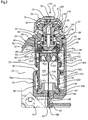
Figure 1 is a front perspective view of a hardwood flooring nailer, comprising a mallet-operated actuator housing according to one embodiment of the present invention; -
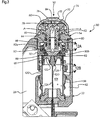
Figures 2-7 are partial sectional elevations of the actuator housing offigure 1 , and show the sequential movement of the components of the actuator cartridge during a fastener discharge cycle of the nailer; -
Figure 8 is a partial sectional elevation of the actuator housing offigure 1 , and shows the actuator cartridge disconnected from the casing and extracted therefrom; -
Figure 9 is a view similar tofigure 8 but showing the actuator head disconnected from the piston assembly, and the plunger of the piston assembly extracted out of the cylinder of same; -
Figure 10 is an enlarged perspective view of the actuator cartridge of the previous figures; -
Figure 11 is an enlarged perspective view of the striking rod and of the fastener receiving assembly; -
Figures 12A and 12B are enlarged partial sectional elevations substantially circumscribed within double-pointed arrows figure 3 , respectively showing the threading engagement of the actuator head in the casing opening, and the threading engagement of actuator head with the piston assembly cylinder; -
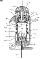
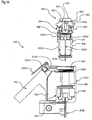
Figure 13 is a sectional perspective view of a switch-operated nailer according to an alternate embodiment of the invention; and -
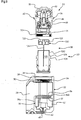
Figure 14 is a sectional elevation of the switch-operated nailer offigure 13 , with the actuator cartridge extracted from the casing. -
Figure 1 shows apneumatic nailer 10. The illustratednailer 10 is of the type used to secure hardwood flooring planks to a subfloor. It is however understood that the present invention could extend to any kind of pneumatic fastener driving tool. - Nailer 10 comprises a C-
shaped frame 12, made of moulded metal for example, carrying ashoe 14 at its bottom end portion.Shoe 14 will rest on a subjacent workpiece, such as a tongue-and-groove hardwood plank P, prior to driving a fastener therein. - C-
shaped frame 12 defines a handle portion 16 integrally carried at one end of anarm portion 18 and extending transversally relative thereto.Arm portion 18 also integrally carries anactuator housing 20 according to the present invention, at its end opposite handle portion 16. -
Actuator housing 20 is best shown infigures 2-9 , although its internal components are only thoroughly numbered infigure 2 .Actuator housing 20 comprises ahollow casing 22, in turn defining amain chamber 23 therein.Main chamber 23, even though it is shown confined withincasing 22, could further extend into other portions of frame 12 (arm portion 18 and handle portion 16). - In the illustrated embodiment,
casing 22 is a moulded section offrame 12. In another embodiment,casing 22 could be distinct fromframe 12 and bolted thereto instead of being a moulded section thereof, as shown for example inUS Patent No. 6,834,789 (from inventors Dion et al. ). - A compressed air source (not shown) feeds compressed air into
main chamber 23 through the instrumentality of a hose (not shown) connected to a conventional compressed air inlet (not shown) made throughcasing 22 and opening intomain chamber 23.Casing 22 further comprises a cartridge insertion opening 24 made in the casing's upper wall. As best seen infigure 9 , opening 24 can be decomposed in three tiers: (1) an outermostannular depression 26 recessed in the outer surface ofcasing 22; (2) a cylindricalintermediate portion 28 juxtaposed to and diametrically smaller thanannular depression 26; and (3) a cylindrical innermost threadedportion 30, opening into the hollow ofcasing 22. -
Main chamber 23 withincasing 22 is separated from anauxiliary chamber 32 by a mouldedpartition 34.Partition 34 defines anupright wall 34a extending upwardly from the internal bottom wall of casing 22, and a top wall 34b transversal toupright wall 34a and having a circularcylinder insertion opening 36 made therethrough, coaxial to the circularcartridge insertion opening 24.Cylinder insertion opening 36 is lined with sealing means in the form of a rubber O-ring 37. - Moreover, a
circular bottom opening 38 and an annular shoulder 40 just abovebottom opening 38, are made on abottom wall 33 ofauxiliary chamber 32.Casing 22 comprises a mushroom-shapedguiding piece 42, a bottom portion of which is snugly inserted in casingbottom opening 38, and a relatively larger head portion thereof abutting on shoulder 40. Guidingpiece 42 defines acentral slit 43, for sliding engagement by astriking rod 124 ofactuator cartridge 50. In addition, withinauxiliary chamber 32 is provided ashock absorber 44 snugly received in annular shoulder 40 and resting against guidingpiece 42. - Just beneath guiding
piece 42 is provided a fastener receiving assembly 138 (best shown infigure 11 ), formed of a bolted assembly of twoplates Plate 140 defines a fastener-shapedopening 144 therein, andplates fastener striking channel 146 extending edge-to-edge acrossplate assembly 138.Fastener striking channel 146 is axially aligned with the longitudinal axis of guiding piece slit 43 and ofstriking rod 124, and opens at afastener ejection opening 148.Fastener striking channel 146, as described hereafter, will be forcibly swept by strikingrod 124. -
Nailer 10 can also be provided with a fastener feeder in the form of an elongated magazine (not shown) affixed to frame 12. The magazine is for holding a supply of fasteners (not shown), e.g. a strip of metallic staples or L- or T-shaped barb-provided cleats commonly used in floor assembling duties, and for loading them serially intofastener striking channel 146 through fastener-shapedopening 144 inplate 140. A fastener loaded inchannel 146 when the latter is swept by striking rod will be struck and thereby and forcibly ejected of the nailer throughfastener ejection opening 148. - An
actuator cartridge 50 according to a first embodiment of the present invention is shown infigures 2-10 .Actuator cartridge 50 is partially inserted incasing 22 and is connected thereto, and is integrally releasable therefrom, as described hereinafter. -
Actuator cartridge 50 is received incasing 22 throughcartridge insertion opening 24.Actuator cartridge 50 comprises anactuator head 54 releasably secured to apiston assembly 58. Aprotective plastic cap 55 is snap-fitted onactuator head 54. -
Actuator head 54 comprises a rigidmetallic shell 60 screwed and thus releasably connected tocartridge insertion opening 24, as best seen infigure 12A . Back tofigure 2 ,shell 60 is partially hollow and defines ahead chamber 64 therein, which opens at opening 61 made across the top wall ofshell 60.Shell 60 also defines anouter portion 62 extending outwardly ofcasing 22, which in turn defines anannular flange 66, received indepression 26 ofcasing 22.Outer shell portion 62, beneathflange 66, integrally merges with anintermediate shell portion 68. An O-ring 27 located at the junction between shellouter portion 62 andintermediate portion 68 ensures airtight interconnection ofactuator head 54 andcasing 22.Intermediate shell portion 68 is received incartridge insertion opening 24, and alower section 69 ofintermediate shell portion 68 is peripherally threaded and can threadingly engage threadedportion 30 ofcartridge insertion opening 24. Fromintermediate shell portion 68 integrally downwardly depends an inner portion, orskirt portion 70.Skirt portion 70, as best shown infigure 10 , is cylindrical and extends within casing 22 towardspiston assembly 58.Skirt portion 70 defines a number of wide, peripherally spaced-apartair inlet windows 72 made therethrough. Thelower rim 71 ofskirt portion 70 has a threaded inner wall, and can be screwed on a correspondingly threadedannular projection 104 on apiston assembly cylinder 100, as further described below. - A number of movable components are nested within
actuator head 64. Abarrel member 74 is slidably received inhead chamber 64.Barrel member 74 comprises anupper stub portion 76 extending and projecting outwardly oftop opening 61 made inshell 60.Upper stub portion 76 carries adiscoid impact plate 75 at its outer free end, which in turn abuts on the inner surface of protectiveplastic cap 55. At its end oppositeimpact plate 75,stub portion 76 merges with a cylindrical and tubular elongated slidingportion 78. Slidingportion 78 is sized to freely and slidably engage the upper, correspondingly cylindrical portion ofhead chamber 64. Anannular depression 79 is made peripherally on the outer peripheral wall of slidingportion 78. Beneath this depression, slidingportion 78 carries annular sealing means in the form of arubber U-cup 80. Furthermore,opposite stub portion 76, slidingportion 78 carries a widened,discoid head portion 82. In one embodiment,head portion 82 is releasable from slidingportion 74. Aroundhead portion 82 is wrapped an annular sealing means in the form of a U-cup 83. - An
air exhaust channel 84 extends acrossbarrel member 74. Exhaust channel opens at the junction betweenhead portion 82 and slidingportion 78, extends longitudinally along slidingportion 78, and opens into the atmosphere through a slanted opening made instub portion 76. - Moreover, a
cylindroid valve 88 is movably slidably received inhead chamber 64, and a U-cup 87 permits airtight engagement of the outer peripheral wall ofvalve 88 on the inner peripheral wall ofhead chamber 64 in all positions ofvalve 88. Compressed air is thus never allowed to flow frommain chamber 23 intohead chamber 64 by seeping through the interstice formed between the outer wall ofvalve 88 and the peripheral wall ofhead chamber 64.Valve 88 is carried at the lower end portion ofbarrel member 74 coaxially thereto, andhead portion 82 ofbarrel member 74 occupies avalve chamber 90 withinvalve 88.Valve chamber 90 is cross-sectionally circular, and defines anupper portion 90a diametrically larger than alower portion 90b thereof. Moreover,valve 88 defines a downwardly dependingskirt portion 91, through which are made elongated, peripherally spaced apart air inlets 92 (figure 10 ).Valve 88 further comprises a number of L-shapedair channels 89, opening on one end inmain chamber 23, and at the other end inhead chamber 64. - As can be seen in the figures,
movable valve 88 is at least partially surrounded byskirt 70 ofactuator head shell 60. Therefore, to preventshell skirt 70 to interfere with the movement ofvalve 88, the outer diameter ofvalve 88 is smaller than the inner diameter ofshell skirt portion 70. - As briefly mentioned above,
actuator head 54 is releasably connected to apiston assembly 58.Piston assembly 58 comprises a tubular member in the form ofcylinder 100, in which is slidably mounted aplunger 120 for reciprocating movement therein.Cylinder 100 defines acylinder chamber 101 therein. -
Cylinder 100 defines anupper rim portion 102 circumscribing a top opening of the cylinder chamber.Skirt portion 91 ofvalve 88 is slidably wrapped aroundupper rim portion 102. Moreover,cylinder 100 integrally defines a radially projectingannular portion 104 having a peripherally threaded outer surface;annular portion 104 is diametrically wider than the adjacentupper rim portion 102. The skirtlower rim 71 ofactuator head shell 60, whose inner surface is threaded, is screwed to annular threadedportion 104, andactuator head 54 andpiston assembly 58 are thereby interconnected in a releasable fashion, as best seen infigure 12B . - Back to
figure 2 , a lower end portion ofcylinder 100 is received inauxiliary chamber 32 ofcasing 22 throughcircular cylinder opening 36 made in partition top wall 34b. The outer surface ofcylinder 100 engagesseal 37 peripherally liningcylinder opening 36, ensuring an airtight connection therebetween. Thelower rim 106 ofcylinder 100 is snugly received in airtight fashion in a gap formed betweenshock absorber 44 and shoulder 40 made on auxiliary chamberbottom wall 33, andshock absorber 44 partly extends intocylinder chamber 101. - Moreover, a number of
exhaust holes 108 are made throughcylinder 100, which are unidirectionally obstructed by anelastic band 110 engaged in a cross-sectionally V-shaped annular and peripheral groove made on theexternal surface cylinder 100. Exhaust holes 108 allow unidirectional radially outward air flow betweencylinder chamber 101 and auxiliary chamber 32: air can flow fromcylinder chamber 101 towardsauxiliary chamber 32 throughexhaust holes 108 by deformingly biasingelastic band 110 radially outwardly and by seeping betweenelastic band 110 and cylinder's outer surface. However, air is prevented from flowing in the opposite, radially inward direction since theelastic band 110 obstructs exhaust holes 108. Furthermore, relative larger unobstructed transfer holes 112 are made below exhaust holes 108, adjacent the lower rim of the cylinder. - As mentioned above, a
plunger 120 is slidably mounted withincylinder 100. As bet seen infigures 2 and9 ,plunger 120 defines adiscoid plunger head 122, whose peripheral wall slidably engages in the inner peripheral wall ofcylinder 100. The slidable engagement ofplunger head 122 on the inner peripheral wall ofcylinder 100 is kept airtight by aperipheral sealing band 123. Furthermore, the shape of the undersurface ofplunger head 122 is made complementary to the shape ofshock absorber 44. - The undersurface of
plunger head 122 centrally carries a cross-sectionally rectangular striking rod 124 (seefigure 11 ).Striking rod 124 extends through the central opening ofshock absorber 44, and slidably engagescentral slit 43 in guidingpiece 42. Asplunger 120 moves downwardly intocylinder chamber 101,striking rod 124 will axially sweepfastener ejection channel 146 inplate assembly 138, in which fasteners are destined to be loaded, as mentioned above. - For more elaborate details concerning the actuator housing and its internal components described above, it is possible to consult
US Patent No. 6,834,789 (from inventors Dion et al .), which describes a similar actuator housing. It is to be noted that US Patent No. 6,834,789 however does not disclose an actuator cartridge releasable "as one" from the actuator casing. It rather discloses an actuator head separate unconnected to and distant from the piston assembly. The piston cylinder inUS patent No. 6,834,789 is permanently affixed to the casing. - To use the nailer,
actuator cartridge 50 must be properly assembled and properly secured tocasing 22. More particularly,actuator head 54 must be properly secured topiston assembly 58 by maximum screwing of shell skirtlower rim 71 onto annular threadedportion 104 ofpiston cylinder 100.Skirt rim 71 should firmly abut against astopper ring 105 projecting integrally radially from the outer surface ofcylinder 100 and located beneath annular threadedportion 104. Moreover,actuator cartridge 50 must be suitably secured to casing 22 by maximal screwing ofactuator head 54 incartridge insertion opening 24, by meshing the threadedsection 69 of shellintermediate portion 68 in threadedportion 30 ofcartridge insertion opening 24. Shellannular flange 66 should be firmly pressed againstannular depression 26 provided aroundopening 24. - In order to use
nailer 10, a compressed air source must be operatively connected to casing 22, and must be activated in order to feed compressed air intomain chamber 23 and keep the latter pressurized. - A workman starts by suitably positioning
nailer shoe 14 above a workpiece to be nailed. Then, to trigger the nailer, the workman must forcibly poundactuator head 54 using a mallet for example. - At rest, all components of the nailer are positioned as shown in
figure 2 . In this configuration: -
barrel member 74 is moved to an upper limit position, andimpact plate 75 is spaced away from the upper surface ofactuator head shell 60. In this upper limit position ofbarrel member 74,U-cup 80 of slidingportion 78 sealing engages the inner wall ofhead chamber 64. This sealing engagement prevents air located intohead chamber 64 to be exhausted out ofhead chamber 64 through slantedopenings 63 made inshell 60, opening intohead chamber 64 at one end and outwardly ofshell 60 into the atmosphere at the other end. In this position ofbarrel member 74, fluid communication betweenhead chamber 64 and the atmosphere is thus blocked; -
plunger 120 is moved to its upper limit position, and the top surface ofplunger head 122 is at the same level than the top circular edge ofcylinder rim portion 102. In this upper limit position,striking rod 124 substantially clearsfastener striking channel 144; -
valve 88 is moved towards cylinderouter rim portion 102 and sealing engages its upper free edge. In this configuration, theair inlets 92 on the side ofvalve skirt 91 are completely covered and obstructed by the outer peripheral surface ofcylinder rim 102, and fluid communication between the pressurizedmain chamber 23 and the top opening ofcylinder 100 is blocked. Moreover, the relative position of barrelmember head portion 82 andvalve 88 is such thathead portion U-cup 83 clears the peripheral wall ofvalve chamber 90. Thus, the entirety ofvalve chamber 90 communicates with the atmosphere throughexhaust channel 84, and atmospheric pressure is applied to the top surface ofplunger head 122. Moreover, in this position,air channels 89 are unobstructed and allow pressurized air to flow from pressurizedmain chamber 23 intohead chamber 64. - When a workman strikes
actuator head 54 with a mallet or any other heavy tool,impact plate 75 is forced downwardly until it abuts against theupper surface shell 60, as shown infigure 3 .Barrel member 74 is thereby axially moved downwardly along withimpact plate 75, which causes U-cup 80 to clear the peripheral wall ofhead chamber 64. This unsealing opens up a passage betweenhead chamber 64 and the atmosphere, and the pressurized air contained inhead chamber 64 is evacuated through slantedopenings 63 as suggest by arrows A infigure 3 . The pressure withinhead chamber 64 thus suddenly drops to atmospheric pressure. The downward motion ofbarrel member 74 also causeshead portion 82 to move within valveinner chamber 90, and U-cup 83 to come in sealing engagement against the peripheral wall of valve chamberlower portion 90b. This interrupts fluid communication between the atmosphere and the volume ofvalve chamber 90 beneath barrelmember head portion 82 and aboveplunger head 122. - The pressure within
head chamber 64 having dropped to atmospheric pressure, the relatively high pressure in main chamber acting upwardly on the horizontal surfaces ofvalve 88, as suggested by arrows B onfigure 4 ,slidably urge valve 88 upwardly. This upward movement ofvalve 88 causesair channels 89 be become almost completely sealed by the inner peripheral wall ofshell skirt 70. Also, asvalve 88 moves upwardly,air inlets 92 onvalve skirt 90 are cleared by the outer peripheral surface ofcylinder rim portion 102, and fluid communication is established between the pressurizedmain chamber 23 and the portion ofcylinder chamber 101 aboveplunger head 122. Pressurized air inmain chamber 23 can thus flow throughshell skirt windows 71, throughair inlets 92 invalve skirt 91, and intocylinder chamber 101, as suggested by arrows C infigure 5 . Pressurized air therefore applies a very important downward pressure on the upper surface ofplunger head 122 as suggested by arrows C' infigure 5 , which causesplunger 120 to be urged downwardly. Plungerstriking rod 124 concomitantly sweeps thefastener striking channel 146 inplate assembly 138, strikes the fastener loaded therein, ejects it through fastener ejection opening 148 and drives it into theworkpiece underlying nailer 10. - As
plunger 120 is urged downwardly, the volume of air incylinder chamber 101 located beneathplunger head 122 is forced into auxiliary chamber principally through unobstructed transfer holes 112, as suggested by arrows D infigure 5 . - Concomitantly, pressurized air acting on the bottom surface of barrel
member head portion 82, as suggested by arrows E infigure 5 , and eventually causesbarrel member 74 to be urged upwardly back to its upper limit position, as shown infigure 6 . Therefore,U-cup 80 on barrelmember sliding portion 78 returns in sealing engagement on the peripheral wall ofhead chamber 64, and fluid communication betweenhead chamber 64 and the atmosphere throughopenings 63 is interrupted. - Displacement of
plunger 120 is stopped when the undersurface ofplunger head 122 impacts and comes in snug engagement against shock absorber 44 (figure 6 ). Whenplunger 120 is in this lower limit position, cylinder chamber abovepiston head 122 is still in fluid communication with pressurizedmain chamber 23, and the upper surface ofplunger head 122 is located below and clears unidirectional exhaust holes 108. Therefore, air flows frompressurized cylinder chamber 101 radially outwardly into the relatively low pressureauxiliary chamber 32 throughexhaust holes 108 as suggested by arrows F infigure 6 , andauxiliary chamber 32 becomes substantially pressurized. - Concomitantly, pressurized air seeps gradually back from
main chamber 23 into the sealedhead chamber 64 through the not-entirely sealedair channels 89 onvalve 88. Indeed, although the end ofair channels 89 is almost entirely obstructed and sealed by the inner peripheral wall ofshell skirt 70, a very narrow clearance remains therebetween allowing compressed air to flow at a very low rate frommain chamber 23 throughair channels 89 and intohead chamber 64, as suggested by arrows G infigure 6 . Ashead chamber 64 slowly but surely pressurizes,valve 88 moves gradually downwardly untilair channels 89 are again completely unobstructed by the inner peripheral wall ofskirt 71. Oncevalve 88 has moved sufficiently downwardly so thatair channels 89 are cleared by the inner peripheral wall ofshell skirt 70, the air flow frommain chamber 23 intohead chamber 64 is greatly accelerated,head chamber 64 becomes instantly pressurized, andvalve 88 is briskly urged downwardly so as to come in pressing and sealing engagement against the upper free edge ofpiston cylinder 100, as shown infigure 7 . At this point, fluid communication betweencylinder chamber 101 andmain chamber 23 is interrupted. Also, in this position ofvalve 88, the U-cup 83 around barrelmember head portion 82 clears the peripheral wall of valveinner chamber 90, and fluid communication betweenvalve chamber 90 and the atmosphere is re-established throughexhaust channel 84. Therefore, the pressurized air that remains incylinder chamber 101 aboveplunger head 122 thus escapes through theexhaust channel 84 into the atmosphere, as indicated by arrows H infigure 7 . - At this point, since atmospheric pressure is now applied on the upper surface of
plunger head 122, the pressurized air into auxiliary chamber can decompress by flowing back intocylinder chamber 101 beneathplunger head 122 throughtransfer holes 112 as indicated by arrows I infigure 7 , thereby urgingplunger 120 back towards its upper limit position. The nailer is then ready to start another nailing cycle. - After repeated uses of the nailer, the necessity of performing maintenance tasks on the actuator mechanism becomes advisable and sometimes mandatory. This is greatly facilitated with the present invention. Indeed, an important advantage of the present invention is that the
actuator cartridge 50 can be very easily extracted from casing 22, as suggested infigure 8-9 . Indeed, to perform maintenance tasks on the actuator mechanism, the user can simply graspactuator head 54 and twist it in the "unscrewing" direction. This causesthreads 69 ofintermediate portion 68 ofactuator head shell 60 to slide against the threads of threadedsection 30 ofcartridge insertion opening 24, and the connection betweenactuator head 54 andcasing 22 to loosen. - To prevent disconnection of
actuator head 54 frompiston assembly 58 when theactuator head 54 is unscrewed from casingopening 24, the thread pitch of both threaded interconnections is different. More particularly, the thread pitch of the cooperating threadedsections actuator head 54 andcasing opening 24 respectively, is greater than the thread pitch of the cooperating threadedsections actuator head 54 andcylinder 100. In practise, this translates in a different number of turns needed for undoing the two threaded interconnections: for example, unscrewing ofactuator head 54 from casingopening 24 may necessitate 5 turns, and unscrewing ofactuator head 54 frompiston assembly 58 may necessitate 10 turns. By providing different thread pitches,actuator head 54 hence cannot be entirely disconnected frompiston assembly 58 asactuator head 54 is rotated and unscrewed from casingopening 24. - It is understood that any other suitable technique could be used to prevent disconnection of
actuator head 54 fromcylinder 100 asactuator head 54 is disconnected from casing 22. For example, a small compressible plastic fitting could be received in a corresponding cavity made in either one of the cooperating threadedsections cylinder 100 oractuator head 54 respectively. Such a plastic fitting would oppose a certain resistance to the sliding of the threads of actuator head threadedsection 71 about those of cylinder threadedsection 104, and thus prevent disconnection ofcylinder 100 fromactuator head 54 asactuator head 54 is unscrewed from casingopening 24. - The threading interconnection of
actuator head 54 withcasing opening 24 is the only connectionfastening actuator cartridge 50 tocasing 22. Thus, whenactuator head 54 is completely unscrewed and thus disconnected from casingopening 24, the only connection ofactuator cartridge 50 tocasing 22 is undone, andactuator cartridge 50 can be entirely extracted from casing 22, as shown infigure 8 . Thus,actuator head 54,piston assembly 58, and their respective constituents can be extracted from casing 22, simply by disconnectingactuator head 54 fromcasing 22. Asactuator cartridge 50 is extracted out ofcasing 22,plunger 120 clings to the inner peripheral wall ofcylinder 100 due to the friction at the contact between sealingband 123 aroundplunger head 122 andcylinder 100. If ever plunger 120 were to accidentally slide out ofcylinder 100 and remain in casing 22 asactuator cartridge 50 is extracted therefrom, the workman could simply insert his hand in the casing or flip the nailer upside down in order to separately extract the plunger from the casing. - Once actuator cartridge has been extracted out of
casing 22, the workman can disconnectactuator head 54 frompiston assembly 58, by graspingactuator head 54 in one hand, andpiston assembly 58 in the other hand and twisting in the "unscrewing" direction. This causes the threads on the inner wall of skirt rim 71 ofactuator head 54 to slide against the threads of cylinderannular portion 104 untilactuator head 54 andpiston assembly 58 detach from each other. Thereafter,actuator head 54 can be further disassembled by sequentially removing its internal constituents (valve, barrel member, etc.), andplunger 120 can be slid out ofcylinder 100. - By providing an assembled
actuator cartridge 50 which can be connected and disconnected "as one" from casing 22, it becomes significantly easier to clean, repair, lubricate, or generally maintain each individual component of the actuator mechanism. With prior art pneumatic nailers, the casing containing the actuator mechanism had to be opened up in order to gain access to certain components of the actuator mechanism. Advantageously, this is not the case with the present invention. - Once the proper maintenance tasks have been performed on the nailer, it is easy to reassemble the nailer in working configuration. The workman must first reassemble
actuator cartridge 50 by following the above disassembly instructions in the reverse order. When actuator cartridge is reassembled, the workman positionsplunger head 122 next to the lower end of thecylinder rim 106 in order for thestriking rod 124 to be extracted as much as possible from thecylinder 100. The workman then takes note of the orientation of cross-sectionally rectangular guiding piece slit 43, and inserts theactuator cartridge 50 incasing 22 throughcartridge insertion opening 24 such that the cross-sectionally rectangularstriking rod 124 be properly angularly lined up with guiding piece slit 43. Ascartridge 50 is progressively inserted incartridge insertion opening 24, the lower portion ofcylinder 100 entersauxiliary chamber 32 throughcircular opening 36 made in partition top wall 34b, and thestriking rod 124 becomes engaged in guiding piece slit 43. The workman then starts to screwactuator head 54 incartridge insertion opening 24. Asactuator head 54 is rotated, all components of the cartridge are rotated therealong with the exception ofplunger 120, since its cross-sectionally rectangularstriking rod 124 is non-rotatably engaged in guiding piece slit 43.Sealing band 123 aroundplunger head 122 therefore slides against the inner wall ofcylinder 100 asactuator head 54 is screwed tocasing 22. The nailer is ready for use whenactuator head 54 is tightly screwed incartridge insertion opening 24. -
Nailer 10, in which selective activation of the actuator cartridge is accomplished by pounding the actuator head with a mallet, is an exemplary embodiment, and the scope of the present invention should extend to other types of pneumatic nailers, such as the switch-activatednailer 310 offigures 13-14 . -
Nailer 310 has certain similarities with nailer 10: it comprises a main frame 312 (shaped differently thanmain frame 12 of nailer 10) in turn defining acasing 322. Afastener receiving assembly 3138 is attached tocasing 322. Casing 322 defines therein amain chamber 323, and anauxiliary chamber 332 separated frommain chamber 323 by apartition 334. Casing 322 further defines a topcircular opening 324 whose peripheral wall inter alia defines a threadedsection 330. Within saidcasing 322 is releasably received anactuator cartridge 350. -
Actuator cartridge 350 is similar tocartridge 50 ofnailer 10, but is not mallet-operated. It comprises anactuator head 354 having ashell 360, in turn defining anouter portion 362, anintermediate portion 368 defining a threadedsection 369 for threading engagement with threadedsection 330 of casingcircular opening 324, and an inner orskirt portion 370 extending withincasing 322.Skirt portion 370 defines alower rim 371 having a threaded inner wall. - Within
actuator head 354 is provided abarrel member 374, which is fixedly or releasably connected to shell 360.Barrel member 374 does not move withinactuator head shell 360 during a fastener discharge cycle, contrarily tobarrel member 74 ofnailer 10. Moreover,valve 388, mounted aroundbarrel member 374 and sliding axially on the upper rim portion ofcylinder 3100, does not present air channels such as the L-shapedchannels 89 invalve 88 ofnailer 10. -
Actuator head 354 is releasably connected to apiston assembly 358 by screwing of skirtlower rim 371 around an annular threadedportion 3104 ofcylinder 3100 of asubjacent piston assembly 358, as inactuator cartridge 50 ofnailer 10 described above. Aplunger 3120 carrying astriking rod 3124 is slidably mounted insidecylinder 3100. - In
nailer 10, downward movement ofbarrel member 74 is provoked when someone strikes the actuator head with a mallet. This downward movement ofbarrel member 74 causes the depressurization of head chamber 64 (as described above), which in turn causesvalve 88 to be urged upwardly and allow pressurized air frommain chamber 23 to access and flow into the cylinder chamber and forcibly drive the plunger towards its bottom limit position. The downward stroke of the plunger drives its striking rod across to the fastener striking channel inplate assembly 138. - In
nailer 310, instead of striking the actuator head with a mallet to trigger a fastener discharge cycle, the workman pushes aswitch lever 3200.Switch lever 3200 acts upon aselector valve 3202 which controls inlet of pressurized air insidehead chamber 364, abovevalve 388, via anelongated air channel 3206 made in the thickness of the top wall ofcasing 322. Whenswitch lever 3200 is not pressed,selector valve 3202 is set to route compressed air from pressurizedmain chamber 323 intohead chamber 364, therefore urgingvalve 388 towards its closed position. To trigger a discharge cycle of the nailer, the workman applies pressure on theswitch lever 3200, which shifts theselector valve 3202 and sets it to cut off communication betweenhead chamber 364 and pressurizedmain chamber 323, and to establish fluid communication between the atmosphere andhead chamber 364. Thus, when a workman depresses theswitch lever 3200,head chamber 364 is depressurized as compressed air is exhausted throughchannel 3206,valve 388 is urged to its open position, and compressed air is thus admitted intocylinder chamber 3101 to urgeplunger 3120 towards its bottom limit position. When the workman releases switchlever 3200,head chamber 364 is re-pressurized,valve 388 is urged towards its closed position, and the pressurized air above the plunger head is exhausted throughexhaust channel 384 made acrossbarrel member 374 and out into the atmosphere throughexhaust holes 363 made acrossshell 360. - Similarly to
actuator cartridge 50 innailer 10,actuator cartridge 350 in nailer 300 is a unitary structure which can be connected and disconnected as one fromcasing 322, in order to easily carry out maintenance thereof. - It is understood that the above-described nailer embodiments are exemplary, and various modifications could be made thereto without departing from the scope of the invention as defined in the appended claims.
- For example, the fastening means allowing the releasable connection of the actuator head to the piston assembly is formed of matching threaded sections on both the actuator head and the piston assembly. It is understood that any other suitable fastening means could be used instead of mutually screwed threaded portions, for example snap-action fastening means. Similarly, any suitable fastening means could be used to ensure the releasable connection of the actuator cartridge to the nailer's casing, for example snap-action fastening means.
- Moreover, in both illustrated embodiments, the actuator cartridge anchoring point to the casing is on the actuator head, i.e. the releasable connection of the actuator cartridge to the casing is achieved by screwing a threaded section of the actuator head shell in a corresponding threaded section of the opening made through the top wall of the casing. It is envisioned that the anchoring point of the cartridge to the casing be located at any other suitable location on the cartridge. The cylinder could for example comprise, on its outer wall, an annular threaded radial projection threadingly engaging mating threads made in the circular opening on the top wall of the partition separating the main chamber from the auxiliary chamber.
- Furthermore, in both illustrated embodiments, the shock absorber (no. 44 in the first embodiment of
figure 2 ), is snugly friction-fitted in the annular shoulder 40 made on thebottom wall 33 of theauxiliary chamber 32. In alternate embodiments, the shock absorber could instead be friction-fitted within the lower rim of the piston assembly cylinder and could freely rest against the auxiliary chamber shoulder. In such an embodiment, the shock absorber would cling to the inner surface of the cylinder chamber as the piston assembly is extracted out of the casing, and would consequently be extracted out of the casing along with the actuator cartridge. - Also, the plunger should not be limited to carrying a striking rod for directly striking and ejecting fasteners. For example, instead of carrying a striking member for directly striking a fastener, the plunger could carry connecting aims transmitting the axial movement of the plunger head to pivotable arms situated outwardly of said casing, as for example disclosed in co-pending international application No.
PCT/CA2005/000804 (inventors Dion et al - The "backstroke" of the plunger, i.e. its return to its upper limit position, was accomplished in the above-described embodiments by providing an auxiliary chamber (chamber 32) separated from
main chamber 23, and communicating withcylinder chamber 101 through unidirectional air exhaust holes 108 and through transfer holes 112. When the plunger reaches its lower limit position, the auxiliary chamber becomes pressurized as compressed air flows from the main chamber into the cylinder chamber, and in turn from the cylinder chamber into the auxiliary chamber through unidirectional air exhaust holes 108. When the pressure above the plunger drops to atmospheric pressure, the compressed air inauxiliary chamber 32 flows back intocylinder chamber 101 beneathplunger head 122 throughtransfer holes 112 and urges the plunger back to its upper limit position. - The nailer casing and the actuator cartridge could be configured differently, such that the "backstroke" of the piston be accomplished as described in the above-mentioned international application No.
PCT/CA2005/000804 US patent No. 3,542,273 (inventor G.R. Hedrick ). In this embodiment, the plunger is composed of a striking rod mounted to a plunger head, the plunger head comprising in turn a discoid member defining a toroidal groove on its upper surface, and a hollow mounting rod mounted to the discoid member and further concentrically and telescopically mounted within a tubular member affixed and depending downwardly from the actuator head.
Claims (17)
- An actuator housing (20) for use on a pneumatic nailer (10), said actuator housing (20) comprising:- a casing (22), at least partially hollow, defining a cartridge insertion opening (24);- a selectively activated actuator cartridge (50) which can be inserted in said casing (22) through said cartridge insertion opening (24),- characterised in that said actuator cartridge (50) comprises:and in that:• an actuator head (54) for sealing engagement with said cartridge insertion opening (24) of said casing (22), said actuator head (54) extending at least partially outwardly of said casing (22),• a piston assembly (100) received at least partially within said casing (22), said piston assembly (100) comprising a tubular member defining a tubular member chamber (101) therein and a plunger (120) at least partially movably mounted within said tubular member chamber;• first fastening means (71, 104) fastening said actuator head (54) to said tubular member of said piston assembly (100); and• releasable second fastening means (24, 54), allowing releasable fastening of said actuator cartridge (50) to said casing (22);- upon selective activation of said actuator cartridge (50), said plunger (120) is actuated along said tubular member chamber (101) for striking a fastener,- said second fastening means (24, 54) can be released to disconnect said actuator cartridge (50) from said casing (22);- said tubular member is a cylinder (100) and said tubular member chamber (101) is a cylinder chamber;- said second fastening means (24, 54) comprise an annular threaded section (104) of said actuator head (54) and an annular threaded section (30) of said cartridge insertion opening (24), to allow said actuator head (54) to be screwed into said cartridge insertion opening (24)
- The actuator housing (20) according to claim 1, wherein said releasable second fastening means (24, 54) connects said actuator head (54) to said casing (22).
- The actuator housing (20) according to claim 1, wherein said first fastening means (71, 104) are releasable.
- The actuator housing (20) according to claim 1, wherein said actuator head (54) defines an inner portion (60) extending within said casing (22), said first fastening means (71, 104) are defined by an annular threaded section (104) of said actuator head inner portion (60) and an annular threaded section (30) of said cylinder (100), to allow said actuator head inner portion (60) and said cylinder (100) to be screwed together.
- The actuator housing (20) according to claim 4, wherein said threaded sections (71, 104) of said first fastening means (71, 104) define a first thread pitch, and said threaded sections (30, 104) of said second fastening means (24, 54) define a second thread pitch greater than said first thread pitch, wherein the difference between said first and second thread pitches provides for a number of turns required to release said first fastening means (71, 104) greater than the number of turns required to release said second fastening means (24, 54).
- The actuator housing (20) according to claim 4, wherein said actuator head inner portion (60) defines air inlets (72) made therethrough.
- The actuator housing (20) according to claim 1, wherein said casing (22) defines a striking member opening (43), and said plunger (120) carries a striking member (124) engageable in said striking member (124) opening (43), said striking member (124) being for striking fasteners.
- The actuator housing (20) according to claim 7, wherein said plunger (120) comprises a plunger head (122) carrying said striking member (124), said plunger head (122) being slidably movable within said tubular member chamber (101) between a first limit position and a second limit position.
- The actuator housing (20) according to claim 7, wherein said casing (22) comprises a guiding piece (42) defining a slit (43) therethrough, said guiding piece slit (43) forming said striking member opening (43).
- The actuator housing (20) according to claim 1, wherein said casing (22) defines a pressurized main chamber (23), and wherein said actuator cartridge (50) further comprises a valve (88); wherein when said actuator cartridge (50) is at rest, said valve (88) is closed and fluid communication between said pressurized main chamber (23) and a portion of said tubular member chamber (101) above said plunger (120) is prevented, and wherein upon activation of said actuator cartridge (50), said valve (88) opens and fluid communication between said tubular member chamber (101) above said plunger (120) and said pressurized main chamber (23) is established to enable pressurized air to act on said plunger (120) and urge it from a first limit position towards a second limit position.
- The actuator housing (20) according to claim 10, wherein said actuator head (54) defines a selectively depressurizable head chamber (64) therein in which said valve (88) is movably mounted, and said tubular member chamber (101) defines an air inlet opening (92), wherein when said actuator cartridge (50) is at rest, said head chamber (64) is pressurized and said valve (88) is moved towards said tubular member air inlet opening (92) and blocks fluid communication between said tubular member chamber (101) above said plunger (120) and said pressurized main chamber (23), and when said actuator cartridge (50) is activated, said head chamber (64) is depressurized and said valve (88) is moved away from said tubular member air inlet opening (92) and permits fluid communication between said tubular member chamber (101) above said plunger (120) and said pressurized main chamber (23).
- A nailer for driving fasteners, comprising :- a frame (12), in turn comprising a casing (22), said casing (22) being at least partially hollow and defining a cartridge insertion opening (24) and a strike member opening (148);- a selectively activated actuator cartridge (50) which can be inserted in said casing (22) through said cartridge insertion opening (24);- a fastener receiving member (138), for receiving loose fasteners to be driven outwardly of said nailer;characterised in that said actuator cartridge (50) comprises:• an actuator head (54) for sealing engagement with said cartridge insertion opening (24) of said casing (22), said actuator head (54) extending at least partially outwardly of said casing (22),• a strike motion assembly received at least partially within said casing (22), said strike motion assembly comprising a chamber member (101) having a wall circumscribing a chamber member enclosure, a strike member mounted to said chamber member, said strike member (124) having a portion engageable in said strike member opening (148), said strike member for striking and ejecting loose fasteners; and a means for mounting said strike member to said chamber member for relative movement of said striking portion into said chamber member enclosure;• first fastening means (71, 104) fastening said actuator head (54) to said chamber member of said piston assembly (58); and• releasable second fastening means (24, 54), allowing releasable fastening of said actuator cartridge (50) to said casing (22);and in that:- upon selective activation of said actuator cartridge (50), said strike member (124) is actuated along said chamber member (101),- said second fastening means (24, 54) can be released to disconnect said actuator cartridge (50) from said casing (22);- said strike motion assembly consists of a piston assembly (58);- said chamber member (101) comprises a cylinder (100);- said strike member (124) is a plunger (120) movably mounted in reciprocating fashion within said cylinder (100);- said second fastening means (24, 54) comprise an annular threaded section (104) of said actuator head (54) and an annular threaded section (30) of said cartridge insertion opening (24), to allow said actuator head (54) to be screwed into said cartridge insertion opening (24)
- A nailer according to claim 12, wherein said releasable second fastening means (24, 54) connects said actuator head (54) to said casing (22).
- A nailer according to claim 12, wherein said first fastening means (71, 104) are releasable.
- A nailer according to claim 12, wherein said actuator head (54) defines an inner portion (60) extending within said casing (22), said first fastening means (71, 104) are defined by an annular threaded section (104) of said actuator head inner portion (60) and an annular threaded section (30) of said cylinder (100), to allow said actuator head inner portion (60) and said cylinder (100) to be screwed together.
- A nailer according to claim 15, wherein said threaded sections (71,104) of said first fastening means (71, 104) define a first thread pitch, and said threaded sections (30, 104) of said second fastening means (24, 54) define a second thread pitch greater than said first thread pitch, wherein the difference between said first and second thread pitches provides for a number of turns required to release said first fastening means (71, 104) greater than the number of turns required to release said second fastening means (24, 54).
- A nailer according to claim 15, wherein said actuator head inner portion (60) defines air inlets (92) made therethrough.
Applications Claiming Priority (1)
| Application Number | Priority Date | Filing Date | Title |
|---|---|---|---|
| PCT/CA2006/000700 WO2007124555A1 (en) | 2006-05-01 | 2006-05-01 | Actuator housing having a releasable actuator cartridge for use on hardwood flooring pneumatic nailers |
Publications (3)
| Publication Number | Publication Date |
|---|---|
| EP2043820A1 EP2043820A1 (en) | 2009-04-08 |
| EP2043820A4 EP2043820A4 (en) | 2010-10-20 |
| EP2043820B1 true EP2043820B1 (en) | 2014-01-01 |
Family
ID=38654997
Family Applications (1)
| Application Number | Title | Priority Date | Filing Date |
|---|---|---|---|
| EP06741441.7A Not-in-force EP2043820B1 (en) | 2006-05-01 | 2006-05-01 | Actuator housing having a releasable actuator cartridge for use on hardwood flooring pneumatic nailers |
Country Status (4)
| Country | Link |
|---|---|
| US (1) | US7946464B2 (en) |
| EP (1) | EP2043820B1 (en) |
| CA (1) | CA2646305C (en) |
| WO (1) | WO2007124555A1 (en) |
Families Citing this family (8)
| Publication number | Priority date | Publication date | Assignee | Title |
|---|---|---|---|---|
| BRPI0923639A2 (en) * | 2008-12-24 | 2017-07-11 | Globalforce Ip Ltd | DRIVE SYSTEM |
| US9662777B2 (en) | 2013-08-22 | 2017-05-30 | Techtronic Power Tools Technology Limited | Pneumatic fastener driver |
| US9618116B2 (en) | 2013-08-27 | 2017-04-11 | Illinois Tool Works Inc. | Ported piston for automatic nailer |
| US10265840B2 (en) | 2014-11-10 | 2019-04-23 | Powernail Company | Adjustable fastener-driving tool support system |
| CN104612386A (en) * | 2015-02-02 | 2015-05-13 | 台州市大江实业有限公司 | Floor gun firing device |
| US20170050304A1 (en) * | 2015-08-19 | 2017-02-23 | Wen-Sheng Huang | Barrel assembly of a nail gun |
| US10926389B2 (en) * | 2018-07-31 | 2021-02-23 | Chung-Heng Lee | Powder-actuated tool |
| EP4211378A1 (en) * | 2020-09-10 | 2023-07-19 | Globalforce IP Limited | Improvements in, or relating to, trigger valves |
Family Cites Families (27)
| Publication number | Priority date | Publication date | Assignee | Title |
|---|---|---|---|---|
| US2353450A (en) * | 1943-01-11 | 1944-07-11 | Chicago Pneumatic Tool Co | Dimpling tool |
| US2881738A (en) * | 1956-11-29 | 1959-04-14 | Signode Steel Strapping Co | Piston and staple driver combination |
| US3051135A (en) * | 1959-03-27 | 1962-08-28 | Bostitch Ind Stapling Machine | Pneumatic tool |
| US3035268A (en) * | 1959-10-05 | 1962-05-22 | Modernair Corp | Pneumatically-operated fastener driving machine |
| US3281046A (en) * | 1965-03-25 | 1966-10-25 | Bostitch Inc | Fastener driving apparatus |
| US3360176A (en) * | 1966-04-07 | 1967-12-26 | Gehl | Locating and positioning fixture for nailing machines |
| US3542273A (en) * | 1968-05-14 | 1970-11-24 | Textron Inc | Impact blow actuated pneumatic fastener driving device |
| US3636707A (en) * | 1970-07-22 | 1972-01-25 | Illinois Tool Works | Power device |
| US3871566A (en) * | 1972-07-25 | 1975-03-18 | Behrens Friedrich Joh | Fastener driver tools |
| US3895562A (en) * | 1973-08-16 | 1975-07-22 | Spotnails | Pneumatically powered fastener-driving tool |
| DE2601836C3 (en) * | 1976-01-20 | 1982-03-04 | Joh. Friedrich Behrens AG, 2070 Ahrensburg | Valve arrangement for a pneumatic nailer |
| US4688710A (en) * | 1984-12-07 | 1987-08-25 | Senco Products, Inc. | Modular tool having interchangeable handle and magazine units |
| US4907730A (en) * | 1989-03-29 | 1990-03-13 | Laboratoire Primatech Inc. | Pneumatic nailer |
| US5251367A (en) * | 1991-08-21 | 1993-10-12 | Equipment Development Company, Inc. | Pneumatically driven descaling tools |
| US5547448A (en) * | 1993-10-28 | 1996-08-20 | Grant W. Robertson | Journal equipped rotational devices and methods of making and balancing the same |
| US5690267A (en) * | 1996-06-14 | 1997-11-25 | Testo Industry Corporation | Mounting structure for staple guns |
| JP3405107B2 (en) * | 1997-01-31 | 2003-05-12 | マックス株式会社 | Pneumatic screw driving machine |
| US5909836A (en) * | 1997-10-31 | 1999-06-08 | Illinois Tool Works Inc. | Combustion powered tool with combustion chamber lockout |
| US6095392A (en) * | 1998-02-13 | 2000-08-01 | Porta-Nails, Inc. | Pneumatic nailer including safety trigger for disabling/enabling operation |
| JP4505796B2 (en) * | 2003-05-26 | 2010-07-21 | 日立工機株式会社 | Driving machine |
| US6805272B1 (en) * | 2003-08-06 | 2004-10-19 | Yang Sen-Mu | Pneumatic nail driver |
| US6837415B1 (en) * | 2003-09-29 | 2005-01-04 | Wen-Sheng Huang | Flooring nailer |
| TWI303596B (en) * | 2004-02-20 | 2008-12-01 | Black & Decker Inc | Oil free head valve for pneumatic nailers and staplers |
| US6834789B1 (en) * | 2004-03-24 | 2004-12-28 | Laboratoire Primatech Inc. | Pneumatic fastener driving tool for hardwood flooring |
| JP4996044B2 (en) * | 2004-07-09 | 2012-08-08 | 日立工機株式会社 | Driving machine |
| US7721817B2 (en) * | 2005-05-18 | 2010-05-25 | Stanley Fastening Systems, L.P. | Fastener driving device with adjustable shoe |
| US7213735B1 (en) * | 2006-03-16 | 2007-05-08 | Panrex Industrial Co., Ltd. | Staple-driving gun capable of ensuring attachment of a seal washer to a sleeve |
-
2006
- 2006-05-01 EP EP06741441.7A patent/EP2043820B1/en not_active Not-in-force
- 2006-05-01 WO PCT/CA2006/000700 patent/WO2007124555A1/en active Application Filing
- 2006-05-01 CA CA2646305A patent/CA2646305C/en active Active
- 2006-05-01 US US12/297,230 patent/US7946464B2/en active Active
Also Published As
| Publication number | Publication date |
|---|---|
| WO2007124555A1 (en) | 2007-11-08 |
| EP2043820A4 (en) | 2010-10-20 |
| CA2646305C (en) | 2013-11-19 |
| EP2043820A1 (en) | 2009-04-08 |
| US20090166392A1 (en) | 2009-07-02 |
| CA2646305A1 (en) | 2007-11-08 |
| US7946464B2 (en) | 2011-05-24 |
Similar Documents
| Publication | Publication Date | Title |
|---|---|---|
| EP2043820B1 (en) | Actuator housing having a releasable actuator cartridge for use on hardwood flooring pneumatic nailers | |
| US7377413B2 (en) | Pneumatic nail gun | |
| US5873510A (en) | Repetitive striking type pneumatically operated nail gun | |
| US11185967B2 (en) | Driving tool | |
| US4197974A (en) | Nailer | |
| US7296721B1 (en) | Pneumatic nail gun having nail pusher | |
| CA2261329C (en) | Pneumatic nailer including safety trigger for disabling/enabling operation | |
| US20140158740A1 (en) | Fastening Tool | |
| US5135152A (en) | Pneumatic fastener driving tool | |
| US7303105B2 (en) | Arcuate fastener nailing device for hardwood flooring | |
| US7014089B2 (en) | Trigger valve apparatus for pneumatic tool | |
| US5205457A (en) | Driving tool and method | |
| JPH07136942A (en) | Fastening metal driving device | |
| MX2011003947A (en) | Pneumatic driving machine. | |
| US20090302087A1 (en) | Adjusting Mechanism for Control Valve of Nail Guns | |
| US6834789B1 (en) | Pneumatic fastener driving tool for hardwood flooring | |
| US7712647B2 (en) | Driving machine | |
| JPH0632308Y2 (en) | Pneumatic nailer | |
| US20080245840A1 (en) | Pneumatic nailer | |
| US20120160889A1 (en) | Fastening Tool for Adjusting a Driving Depth of a Fastener | |
| US20080272326A1 (en) | Driving tool and head valve assembly for a driving tool | |
| US20100006619A1 (en) | Fastener Positioning Assembly for Nail Gun | |
| US10953530B2 (en) | Repeating nail-feeding structure for pneumatic nailing machine | |
| CA2562970C (en) | Arcuate fastener nailing device for hardwood flooring | |
| US3543986A (en) | Extractor for cartridge-actuated device |
Legal Events
| Date | Code | Title | Description |
|---|---|---|---|
| PUAI | Public reference made under article 153(3) epc to a published international application that has entered the european phase |
Free format text: ORIGINAL CODE: 0009012 |
|
| 17P | Request for examination filed |
Effective date: 20080331 |
|
| AK | Designated contracting states |
Kind code of ref document: A1 Designated state(s): AT BE BG CH CY CZ DE DK EE ES FI FR GB GR HU IE IS IT LI LT LU LV MC NL PL PT RO SE SI SK TR |
|
| AX | Request for extension of the european patent |
Extension state: AL BA HR MK YU |
|
| A4 | Supplementary search report drawn up and despatched |
Effective date: 20100917 |
|
| DAX | Request for extension of the european patent (deleted) | ||
| 17Q | First examination report despatched |
Effective date: 20130208 |
|
| GRAP | Despatch of communication of intention to grant a patent |
Free format text: ORIGINAL CODE: EPIDOSNIGR1 |
|
| INTG | Intention to grant announced |
Effective date: 20130731 |
|
| GRAP | Despatch of communication of intention to grant a patent |
Free format text: ORIGINAL CODE: EPIDOSNIGR1 |
|
| GRAS | Grant fee paid |
Free format text: ORIGINAL CODE: EPIDOSNIGR3 |
|
| GRAA | (expected) grant |
Free format text: ORIGINAL CODE: 0009210 |
|
| INTG | Intention to grant announced |
Effective date: 20131113 |
|
| AK | Designated contracting states |
Kind code of ref document: B1 Designated state(s): AT BE BG CH CY CZ DE DK EE ES FI FR GB GR HU IE IS IT LI LT LU LV MC NL PL PT RO SE SI SK TR |
|
| REG | Reference to a national code |
Ref country code: GB Ref legal event code: FG4D |
|
| REG | Reference to a national code |
Ref country code: CH Ref legal event code: EP |
|
| REG | Reference to a national code |
Ref country code: IE Ref legal event code: FG4D |
|
| REG | Reference to a national code |
Ref country code: DE Ref legal event code: R096 Ref document number: 602006039877 Country of ref document: DE Effective date: 20140213 |
|
| REG | Reference to a national code |
Ref country code: AT Ref legal event code: REF Ref document number: 647387 Country of ref document: AT Kind code of ref document: T Effective date: 20140215 |
|
| REG | Reference to a national code |
Ref country code: NL Ref legal event code: VDEP Effective date: 20140101 |
|
| REG | Reference to a national code |
Ref country code: AT Ref legal event code: MK05 Ref document number: 647387 Country of ref document: AT Kind code of ref document: T Effective date: 20140101 |
|
| REG | Reference to a national code |
Ref country code: LT Ref legal event code: MG4D |
|
| PG25 | Lapsed in a contracting state [announced via postgrant information from national office to epo] |
Ref country code: IS Free format text: LAPSE BECAUSE OF FAILURE TO SUBMIT A TRANSLATION OF THE DESCRIPTION OR TO PAY THE FEE WITHIN THE PRESCRIBED TIME-LIMIT Effective date: 20140501 Ref country code: LT Free format text: LAPSE BECAUSE OF FAILURE TO SUBMIT A TRANSLATION OF THE DESCRIPTION OR TO PAY THE FEE WITHIN THE PRESCRIBED TIME-LIMIT Effective date: 20140101 |
|
| PG25 | Lapsed in a contracting state [announced via postgrant information from national office to epo] |
Ref country code: PT Free format text: LAPSE BECAUSE OF FAILURE TO SUBMIT A TRANSLATION OF THE DESCRIPTION OR TO PAY THE FEE WITHIN THE PRESCRIBED TIME-LIMIT Effective date: 20140502 Ref country code: FI Free format text: LAPSE BECAUSE OF FAILURE TO SUBMIT A TRANSLATION OF THE DESCRIPTION OR TO PAY THE FEE WITHIN THE PRESCRIBED TIME-LIMIT Effective date: 20140101 Ref country code: SE Free format text: LAPSE BECAUSE OF FAILURE TO SUBMIT A TRANSLATION OF THE DESCRIPTION OR TO PAY THE FEE WITHIN THE PRESCRIBED TIME-LIMIT Effective date: 20140101 Ref country code: CY Free format text: LAPSE BECAUSE OF FAILURE TO SUBMIT A TRANSLATION OF THE DESCRIPTION OR TO PAY THE FEE WITHIN THE PRESCRIBED TIME-LIMIT Effective date: 20140101 Ref country code: AT Free format text: LAPSE BECAUSE OF FAILURE TO SUBMIT A TRANSLATION OF THE DESCRIPTION OR TO PAY THE FEE WITHIN THE PRESCRIBED TIME-LIMIT Effective date: 20140101 Ref country code: NL Free format text: LAPSE BECAUSE OF FAILURE TO SUBMIT A TRANSLATION OF THE DESCRIPTION OR TO PAY THE FEE WITHIN THE PRESCRIBED TIME-LIMIT Effective date: 20140101 Ref country code: ES Free format text: LAPSE BECAUSE OF FAILURE TO SUBMIT A TRANSLATION OF THE DESCRIPTION OR TO PAY THE FEE WITHIN THE PRESCRIBED TIME-LIMIT Effective date: 20140101 |
|
| PG25 | Lapsed in a contracting state [announced via postgrant information from national office to epo] |
Ref country code: BE Free format text: LAPSE BECAUSE OF FAILURE TO SUBMIT A TRANSLATION OF THE DESCRIPTION OR TO PAY THE FEE WITHIN THE PRESCRIBED TIME-LIMIT Effective date: 20140101 Ref country code: LV Free format text: LAPSE BECAUSE OF FAILURE TO SUBMIT A TRANSLATION OF THE DESCRIPTION OR TO PAY THE FEE WITHIN THE PRESCRIBED TIME-LIMIT Effective date: 20140101 |
|
| REG | Reference to a national code |
Ref country code: DE Ref legal event code: R097 Ref document number: 602006039877 Country of ref document: DE |
|
| PG25 | Lapsed in a contracting state [announced via postgrant information from national office to epo] |
Ref country code: EE Free format text: LAPSE BECAUSE OF FAILURE TO SUBMIT A TRANSLATION OF THE DESCRIPTION OR TO PAY THE FEE WITHIN THE PRESCRIBED TIME-LIMIT Effective date: 20140101 Ref country code: RO Free format text: LAPSE BECAUSE OF FAILURE TO SUBMIT A TRANSLATION OF THE DESCRIPTION OR TO PAY THE FEE WITHIN THE PRESCRIBED TIME-LIMIT Effective date: 20140101 Ref country code: CZ Free format text: LAPSE BECAUSE OF FAILURE TO SUBMIT A TRANSLATION OF THE DESCRIPTION OR TO PAY THE FEE WITHIN THE PRESCRIBED TIME-LIMIT Effective date: 20140101 Ref country code: DK Free format text: LAPSE BECAUSE OF FAILURE TO SUBMIT A TRANSLATION OF THE DESCRIPTION OR TO PAY THE FEE WITHIN THE PRESCRIBED TIME-LIMIT Effective date: 20140101 |
|
| PLBE | No opposition filed within time limit |
Free format text: ORIGINAL CODE: 0009261 |
|
| STAA | Information on the status of an ep patent application or granted ep patent |
Free format text: STATUS: NO OPPOSITION FILED WITHIN TIME LIMIT |
|
| PG25 | Lapsed in a contracting state [announced via postgrant information from national office to epo] |
Ref country code: SK Free format text: LAPSE BECAUSE OF FAILURE TO SUBMIT A TRANSLATION OF THE DESCRIPTION OR TO PAY THE FEE WITHIN THE PRESCRIBED TIME-LIMIT Effective date: 20140101 Ref country code: PL Free format text: LAPSE BECAUSE OF FAILURE TO SUBMIT A TRANSLATION OF THE DESCRIPTION OR TO PAY THE FEE WITHIN THE PRESCRIBED TIME-LIMIT Effective date: 20140101 |
|
| 26N | No opposition filed |
Effective date: 20141002 |
|
| PG25 | Lapsed in a contracting state [announced via postgrant information from national office to epo] |
Ref country code: LU Free format text: LAPSE BECAUSE OF FAILURE TO SUBMIT A TRANSLATION OF THE DESCRIPTION OR TO PAY THE FEE WITHIN THE PRESCRIBED TIME-LIMIT Effective date: 20140501 |
|
| REG | Reference to a national code |
Ref country code: CH Ref legal event code: PL |
|
| REG | Reference to a national code |
Ref country code: DE Ref legal event code: R097 Ref document number: 602006039877 Country of ref document: DE Effective date: 20141002 |
|
| PG25 | Lapsed in a contracting state [announced via postgrant information from national office to epo] |
Ref country code: LI Free format text: LAPSE BECAUSE OF NON-PAYMENT OF DUE FEES Effective date: 20140531 Ref country code: CH Free format text: LAPSE BECAUSE OF NON-PAYMENT OF DUE FEES Effective date: 20140531 Ref country code: MC Free format text: LAPSE BECAUSE OF FAILURE TO SUBMIT A TRANSLATION OF THE DESCRIPTION OR TO PAY THE FEE WITHIN THE PRESCRIBED TIME-LIMIT Effective date: 20140101 |
|
| REG | Reference to a national code |
Ref country code: IE Ref legal event code: MM4A |
|
| PG25 | Lapsed in a contracting state [announced via postgrant information from national office to epo] |
Ref country code: IE Free format text: LAPSE BECAUSE OF NON-PAYMENT OF DUE FEES Effective date: 20140501 |
|
| REG | Reference to a national code |
Ref country code: FR Ref legal event code: PLFP Year of fee payment: 10 |
|
| PG25 | Lapsed in a contracting state [announced via postgrant information from national office to epo] |
Ref country code: SI Free format text: LAPSE BECAUSE OF FAILURE TO SUBMIT A TRANSLATION OF THE DESCRIPTION OR TO PAY THE FEE WITHIN THE PRESCRIBED TIME-LIMIT Effective date: 20140101 |
|
| PGFP | Annual fee paid to national office [announced via postgrant information from national office to epo] |
Ref country code: DE Payment date: 20150521 Year of fee payment: 10 |
|
| PGFP | Annual fee paid to national office [announced via postgrant information from national office to epo] |
Ref country code: FR Payment date: 20150527 Year of fee payment: 10 |
|
| PG25 | Lapsed in a contracting state [announced via postgrant information from national office to epo] |
Ref country code: BG Free format text: LAPSE BECAUSE OF FAILURE TO SUBMIT A TRANSLATION OF THE DESCRIPTION OR TO PAY THE FEE WITHIN THE PRESCRIBED TIME-LIMIT Effective date: 20140101 |
|
| PG25 | Lapsed in a contracting state [announced via postgrant information from national office to epo] |
Ref country code: GR Free format text: LAPSE BECAUSE OF FAILURE TO SUBMIT A TRANSLATION OF THE DESCRIPTION OR TO PAY THE FEE WITHIN THE PRESCRIBED TIME-LIMIT Effective date: 20140402 Ref country code: IT Free format text: LAPSE BECAUSE OF FAILURE TO SUBMIT A TRANSLATION OF THE DESCRIPTION OR TO PAY THE FEE WITHIN THE PRESCRIBED TIME-LIMIT Effective date: 20140101 |
|
| PG25 | Lapsed in a contracting state [announced via postgrant information from national office to epo] |
Ref country code: TR Free format text: LAPSE BECAUSE OF FAILURE TO SUBMIT A TRANSLATION OF THE DESCRIPTION OR TO PAY THE FEE WITHIN THE PRESCRIBED TIME-LIMIT Effective date: 20140101 Ref country code: HU Free format text: LAPSE BECAUSE OF FAILURE TO SUBMIT A TRANSLATION OF THE DESCRIPTION OR TO PAY THE FEE WITHIN THE PRESCRIBED TIME-LIMIT; INVALID AB INITIO Effective date: 20060501 |
|
| REG | Reference to a national code |
Ref country code: DE Ref legal event code: R119 Ref document number: 602006039877 Country of ref document: DE |
|
| REG | Reference to a national code |
Ref country code: FR Ref legal event code: ST Effective date: 20170131 |
|
| PG25 | Lapsed in a contracting state [announced via postgrant information from national office to epo] |
Ref country code: FR Free format text: LAPSE BECAUSE OF NON-PAYMENT OF DUE FEES Effective date: 20160531 Ref country code: DE Free format text: LAPSE BECAUSE OF NON-PAYMENT OF DUE FEES Effective date: 20161201 |
|
| PGFP | Annual fee paid to national office [announced via postgrant information from national office to epo] |
Ref country code: GB Payment date: 20180518 Year of fee payment: 13 |
|
| GBPC | Gb: european patent ceased through non-payment of renewal fee |
Effective date: 20190501 |
|
| PG25 | Lapsed in a contracting state [announced via postgrant information from national office to epo] |
Ref country code: GB Free format text: LAPSE BECAUSE OF NON-PAYMENT OF DUE FEES Effective date: 20190501 |