EP2043303A1 - Transmission system for railway vehicle - Google Patents
Transmission system for railway vehicle Download PDFInfo
- Publication number
- EP2043303A1 EP2043303A1 EP07768202A EP07768202A EP2043303A1 EP 2043303 A1 EP2043303 A1 EP 2043303A1 EP 07768202 A EP07768202 A EP 07768202A EP 07768202 A EP07768202 A EP 07768202A EP 2043303 A1 EP2043303 A1 EP 2043303A1
- Authority
- EP
- European Patent Office
- Prior art keywords
- transmission
- transmitter
- station
- neighboring
- address
- Prior art date
- Legal status (The legal status is an assumption and is not a legal conclusion. Google has not performed a legal analysis and makes no representation as to the accuracy of the status listed.)
- Withdrawn
Links
Images






Classifications
-
- H—ELECTRICITY
- H04—ELECTRIC COMMUNICATION TECHNIQUE
- H04L—TRANSMISSION OF DIGITAL INFORMATION, e.g. TELEGRAPHIC COMMUNICATION
- H04L12/00—Data switching networks
- H04L12/28—Data switching networks characterised by path configuration, e.g. LAN [Local Area Networks] or WAN [Wide Area Networks]
- H04L12/40—Bus networks
- H04L12/403—Bus networks with centralised control, e.g. polling
-
- B—PERFORMING OPERATIONS; TRANSPORTING
- B61—RAILWAYS
- B61L—GUIDING RAILWAY TRAFFIC; ENSURING THE SAFETY OF RAILWAY TRAFFIC
- B61L15/00—Indicators provided on the vehicle or train for signalling purposes
- B61L15/0018—Communication with or on the vehicle or train
- B61L15/0036—Conductor-based, e.g. using CAN-Bus, train-line or optical fibres
-
- H—ELECTRICITY
- H04—ELECTRIC COMMUNICATION TECHNIQUE
- H04L—TRANSMISSION OF DIGITAL INFORMATION, e.g. TELEGRAPHIC COMMUNICATION
- H04L61/00—Network arrangements, protocols or services for addressing or naming
- H04L61/50—Address allocation
- H04L61/5038—Address allocation for local use, e.g. in LAN or USB networks, or in a controller area network [CAN]
-
- H—ELECTRICITY
- H04—ELECTRIC COMMUNICATION TECHNIQUE
- H04L—TRANSMISSION OF DIGITAL INFORMATION, e.g. TELEGRAPHIC COMMUNICATION
- H04L12/00—Data switching networks
- H04L12/28—Data switching networks characterised by path configuration, e.g. LAN [Local Area Networks] or WAN [Wide Area Networks]
- H04L12/40—Bus networks
- H04L2012/40267—Bus for use in transportation systems
- H04L2012/40293—Bus for use in transportation systems the transportation system being a train
Definitions
- the present invention relates to a transmission system for trains.
- address setting switches are installed, each of which is configured to manually set for each transmitter and electrical appliance.
- IPV4 Internet Protocol Version 4: hexadecimal 4 digits
- IPV4 Internet Protocol Version 4: hexadecimal 4 digits
- Patent publication 1 Japanese Patent Application Laid-Open Publication No. H08-237288 (Patent publication 1) has disclosed a technique, in which transmission stations have had different station numbers sequentially set thereon. However, for transmission stations described in this patent reference, if any transmission station had been down in an address setting, the transmission stations would have deviated addresses relative to actual car numbers in a train, thus constituting a difficulty in application to a train monitor to be adapted for a use of addresses of transmission stations to identify or record a failed device.
- the present invention has been devised in view of such problems in the conventional art. It therefore is an object of the invention to provide a transmission system for trains that allows for setup of a network in a train with high redundancy and excellent maintainability.
- a transmission system for trains comprising a plurality of transmitters each respectively provided, every carriage, with a plurality of transmission ports, and adapted to transmit a data received from any transmission port to a necessary transmission port in accordance with a prescribed command, and a plurality of transmission lines adapted for interconnection between neighboring transmitters, and the system being adapted to perform data transmission and reception in a train of carriages in a networking manner
- each transmitter comprises a transmission repeater controller configured to control associated transmission ports, a transmission station configured to follow a command of the transmission repeater controller to set an own transmission station address in the transmitter, and perform data transmission and reception to and from the associated transmission ports, and a bypass configured to keep up a transmission line between neighboring transmitters at both sides of the transmitter even in a trouble of the transmission repeater controller or of any associated transmission port, and wherein, for each transmitter, the transmission station is configured to follow a command from the transmission repeater controller to set an own transmission station address in the transmitter even
- a transmission system for trains allows a network to be set up in a train with high redundancy and excellent maintainability.
- Fig. 1 shows configuration of a transmission system for trains according to the first embodiment of the invention.
- Fig. 2 shows configuration of a transmitter of the transmission system for trains.
- This embodiment includes a total number of n (n: arbitrary integer equal to or larger than 2) transmitters 1a, 1b, 1c, 1d, 1e, ..., 1n installed every carriage in a train, and connected in a point-to-point manner by transmission lines 3a, 3b, 3c, 3d, ..., 3n-1 for transmission and reception of data, and has a pair of displays 2a and 2b connected to the transmitters 1a and 1n in a first carriage and a last carriage, respectively.
- n arbitrary integer equal to or larger than 2
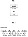
- the data to be transmitted or received by the transmitter 1 is configured with an MAC address, an IP header, a TCP header (or a UDP header), information data, and a CRC check data (FCS).
- an MAC address As shown in Fig. 3 , the data to be transmitted or received by the transmitter 1 is configured with an MAC address, an IP header, a TCP header (or a UDP header), information data, and a CRC check data (FCS).
- FCS CRC check data
- the transmitter 1 is made up by two-port trunk line transmission signal transmitters 5a and 5b, two-port trunk line transmission signal receivers 6a and 6b, a transmission station 7 for transmission and reception of data on own carriage, a transmission repeater controller 4 for controlling respective transmission ports, and a bypass 8 as a bypass device configured for physical interconnection between transmission lines 3 and 3 at both sides of the transmitter 1.
- the bypass 8 is adapted to operate in the event of a fatal failure in the transmitter 1, as well as when no power is supplied, functioning for physical interconnection between upstream transmission line and downstream transmission line to thereby prevent a decoupling of the network, and is composed mechanical relays.
- the transmission station 7 may be disposed inside or outside the transmitter 1. Further, a plurality of transmission stations 7 may be provided.
- the transmission system for trains employs the Class C of private address of IPV4 for addressing the transmission stations, which may follow the Class B or the Class A, or IPV6 or the like.
- transmitters 1a to 1e in the ex-factory state are each given no specific transmission station address, and all have a factory default address (192. 168. 0. 0) as a common address thereto.
- the transmission station 7 when the system is powered before an initial address setting, at each of the transmitters 1a to 1e, the transmission station 7 sends out a neighboring station verification signal to be transmitted downstream, waiting a neighboring station acknowledge signal to be input as a response thereto from downstream.
- the transmission repeater controller 4 is adapted for measurements of an interval of time from the neighboring station verification signal to the neighboring station acknowledge signal, and the amplitude of an input signal to the trunk line transmission signal receiver 6a.
- the transmitters 1a to 1e are each adapted, upon reception of a neighboring station verification signal from upstream, to respond thereto by sending a neighboring station acknowledge signal.
- each transmitter 1i having received a neighboring station acknowledge signal from downstream judges that a downstream transmitter 1 is connected. Accordingly, in the case of Fig.
- the transmitter 1a of the first carriage recognizes that a transmitter 1 resides simply downstream
- each transmitter 1b, 1c, 1d of the second to the fourth carriages recognizes that transmitters 1 reside both upstream and downstream
- the transmitter 1e of the fifth carriage recognizes that a transmitter 1 resides simply upstream.
- the transmitters 1a to 1e are each adapted to judge, from results of the measurements of time interval and amplitude, whether an associated bypass 8 is operated or not. For instance, as shown in Fig. 12 , in the state that the transmitter 1c of the third carriage has been down, and the power of this system is supplied, a neighboring station verification signal from the transmitter 1b is transmitted through a bypass 8 of the transmitter 1b, and received by a trunk line transmission signal receiver 6a of the transmitter 1d, and a neighboring station acknowledge signal from the transmitter 1d is received by a trunk line transmission signal receiver 6b of the transmitter 1b. The neighboring station acknowledge signal is then received by a transmission repeater controller 4 of the transmitter 1b, with a delay of time Tdel to be defined relative to a specified reference value, as follows.
- Tdel 2 ⁇ T ⁇ 1 ⁇ L ⁇ 1 ns
- T1 a signal delay time (ns) per unit distance
- L1 a distance between transmitters (m).
- T1 is approximately 5 (ns)
- L1 a distance between transmitters (m)
- Tdel has a value of approximately 250 (ns). Accordingly, for a delay about 250 ns detected at the transmitter 1b, there is drawn a conclusion such that one associated transmitter 1c is bypassing. For a delay about 500 ns, such a conclusion is to be drawn that two associated transmitters 1c and 1d are consecutively bypassing.
- each transmitter 1a - 1e grasps whether or not a bypass of a neighboring station is in operation, and stores the power-on state of the system.
- the transmitter 1a of the first carriage which has no upstream transmitter connected thereto, is to wait an address setting initiation command from the display 2a, see Fig. 6 .
- the transmitter 1a Upon reception of the address setting initiation command from the display 2a, the transmitter 1a recognizes that it is mounted on the front carriage, and sets up an own transmission station address of the first carriage to be (192. 168. 0. 1).
- the transmitter 1a of the first carriage sends to the transmitter 1b of the second carriage a combination of the own transmission station address (192. 168. 0. 1), a working condition of an associated bypass 8 (i. e. , bypass 8 in the transmitter 1a in this case), and the address setting initiation command.
- this transmitter 1b responds to the address setting initiation command then received, by determining an own transmission station address of the transmitter 1b in accordance with received information including the transmission station address of the transmitter 1a and the working condition of the associated bypass 8.
- the transmitter 1b sets up a one-incremented address (192. 168. 0. 2) as its own transmission station address.
- the transmitter 1c on the third carriage and the transmitter 1d on the fourth carriage set up their own transmission station addresses (192. 168. 0. 3) and (192. 168. 0. 4).
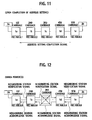
- the transmitter 1e which is mounted on the rearmost carriage, or the fifth carriage, and has recognized that no transmitter resides downstream, sets up its own transmission station address to be (192. 168. 0. 5). Furthermore, as shown in Fig. 11 , the transmitter 1e having set its own transmission station address, or the display 2b having been informed of this state from the transmitter 1e, transmits upstream an address setting completion signal informing of a completion of address setting of transmission stations of whole transmitters 1a to 1e. Then, the transmitters 1a, 1b, 1c and 1d each receive the address setting completion signal, thus recognizing the completion of address setting of transmission stations, respectively. In this state, whole transmitters 1a to 1e have acquired a series of unique addresses (192. 168. 0. 1), (192. 168. 0. 2), (192. 168. 0. 3), (192. 168. 0. 4), and (192. 168. 0. 5) as their own transmission station addresses.
- the address setting is initiated by a command from the display 2a
- the initiation may be done when power is supplied, allowing for an automatic address setting.
- the address setting of own transmission station proceeds like Fig. 6 or Fig. 7 , as it corresponds to a normal case.
- the transmitter 1b of the second carriage sends to the transmitter 1d of the fourth carriage a combination of the own transmission station address (192. 168. 0. 2), the number of bypassed transmitters (one transmitter is bypassed in this case), and the address setting initiation command.
- this combination is received by the transmitter 1d of the fourth carriage, this transmitter 1d responds to the address setting initiation command then received, by determining its own transmission station address in accordance with received information.
- the received address is (192. 168. 0. 2) and one transmitter is bypassed, and the transmitter 1d sets up a two-incremented address (192. 168. 0. 4) as its own transmission station address.
- the address setting of own transmission station proceeds according to processes shown in Figs. 10 and 11 .
- the remaining transmitters each have a unique own transmission station address set up in correspondence to the carriage number, like the normal case, and the address setting is completed.
- the failed transmitter 1c will be recovered, with a default transmission station address (192. 168. 0. 0).
- the transmission system for trains is configured to remake the address setting of whole transmitters, when the transmission station address (192. 168. 0. 0) before address setting is added to the network, so that the respective transmitters 1a, 1b, 1c, 1d, and 1e have their own transmission station addresses (192. 168. 0.1), (192. 168. 0. 2), (192. 168. 0. 3), (192. 168. 0. 4), and (192. 168. 0. 5) set up without changes except for the added transmitter 1c.
- a transmission system for trains is adapted for an automatic setting of unique transmission stations address to each transmitter 1 in the network. Even with a transmitter 1 in trouble, the remaining transmitters 1 have the same transmission station addresses assigned thereto as they would have in a normal case, without having un-matching transmission station addresses to associated carriage numbers, respectively.
- the transmission system for trains thus allows for enhanced redundancy, and rapid construction of network.
- the signal may preferably be sent both downstream and upstream.
- the address setting initiation command may not be accompanied by information on whether a bypass is operated or not, as the discrimination is enabled.
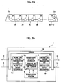
- Fig. 15 shows configuration of a transmission system for trains according to the second embodiment of the invention.
- Fig. 16 shows configuration of a transmitter of the transmission system for trains.
- This embodiment includes a total number of n (n: arbitrary integer equal to or larger than2) transmitters 1a, 1b, ..., 1n installed in every carriage, and connected in a point-to-point manner by transmission lines 3a, 3b, ..., 3(n-1) for transmission and reception of data, and has displays 2a and 2b connected to the transmitters 1a and 1n in the front carriage and the rear carriage, respectively.
- n arbitrary integer equal to or larger than2
- the transmitter 1 is made up by two-port trunk line transmission signal transmitters 5a and 5b, two-port trunk line transmission signal receivers 6a and 6b, a transmission station 7 for transmission and reception of data on own carriage, a transmission repeater controller 4 for controlling respective transmission ports, a bypass 8 as a bypass device configured for physical interconnection between transmission lines 3 and 3 at both sides of the transmitter 1, and a transmission line length memory 9 for storing therein lengths along transmission lines 3 between transmitters 1.
- the bypass 8 is adapted to operate in the event of a fatal failure in the transmitter 1, as well as when no power is supplied, functioning for physical interconnection between upstream transmission line and downstream transmission line to thereby prevent a decoupling of the network, and is composed of mechanical relays.
- the transmission line length memory 9 has stored therein transmission line lengths along respective transmission lines 3a to 3n-1, as exemplified in Fig. 17 .
- the transmission station 7 may be disposed inside or outside the transmitter 1. Further, a plurality of transmission stations 7 may be provided.
- the transmission system for trains employs the Class C of private address of IPV4 for addressing the transmission stations, which may follow the Class B or the Class A, or IPV6 or the like.
- Fig. 18 illustrates a state of the system in which the transmitter 1b of the second carriage has been down, and power is supplied.
- a neighboring station verification signal from the transmitter 1a is transmitted through an operated bypass 8 of the transmitter 1b, and received by a trunk line transmission signal receiver 6a of the transmitter 1c, and as a response thereto, a neighboring station acknowledge signal from this transmitter 1c is received by a trunk line transmission signal receiver 6b of that transmitter 1a.
- the neighboring station acknowledge signal is then received by a transmission repeater controller 4 of the transmitter 1a, with a delay of time Tdel1 to be defined relative to a specified reference value, as follows.
- Tdel ⁇ 1 2 ⁇ T ⁇ 1 ⁇ L ⁇ 1 ns
- T1 a signal delay time (ns) per unit line length
- L1 a line length between transmitters (m).
- T1 is approximately 5 (ns)
- the transmission repeater controller 4 compares the line length L1 between transmitters 1a and 1b, as it is calculated from a measured Tdell, with a line length data in the transmission line length memory 9.
- This line length L1 corresponds to the Tdel1, and a judgment is made of the transmitter1b such that the bypass 8 is operated, and of the transmitter 1c such that its bypass 8 is not operated.
- the transmitter 1c detects a Tdel1 of approximately 200 (ns)
- the transmitter 1d detects a Tdel1 of approximately 350 (ns), with resultant judgments made of the transmitters 1d and 1e such that their bypasses 8 are not operated.
- the transmitter 1a of the first carriage sends to the transmitter 1c of the third carriage a combination of the own transmission station address (192. 168. 0. 1), information on bypass operation (bypassing one transmitter), and an address setting initiation command.
- the transmitter 1e of the fifth carriage sets up its own transmission station address (192. 168. 0. 5).
- the transmitter 1e of the fifth carriage as it has sets up the own transmission station address, sends to whole transmitters 1 an address setting completion signal representing a completion of address setup action.
- the remaining transmitters each have a unique own transmission station address set up in correspondence to the carriage number, like the normal case.
- the failed transmitter 1b will be recovered, with a default transmission station address (192. 168. 0. 0).
- the transmission system for trains is configured to remake the address setting of whole transmitters, when the default transmission station address (192. 168. 0. 0) before address setting is added to the network, so that the respective transmitters 1a, 1b, 1c, 1d, and 1e have their own transmission station addresses (192. 168. 0. 1), (192. 168. 0. 2), (192. 168. 0. 3), (192. 168. 0. 4), and (192. 168. 0. 5) set up without changes except for the added transmitter 1b.
- a transmission system for trains is adapted for an automatic setting of unique addresses to transmission stations of transmitters 1 in the network, even in the case of transmitters 1 installed at uneven spatial intervals. Further, even with a transmitter 1 in trouble, the remaining transmitters 1 have the same transmission station addresses assigned thereto as they would have in a normal case, without having un-matching transmission stations addresses to associated carriages numbers.
- the transmission system for trains thus allows for an enhanced redundancy, and rapid construction of network.
- the present embodiment has been described of an address setting initiation command to be sent together with information on presence or absence of bypass operation and an own transmission station address, there may be sent a transmission station address to be set up in order to avoid sending information on presence or absence of bypass operation. It also is noted that although the present embodiment has been described of a transmission line length between transmitters 1 as a data to be stored in a transmission line length memory 9, there may be employed a method of storing a delay time Tdel of neighboring station acknowledge signal.
Landscapes
- Engineering & Computer Science (AREA)
- Computer Networks & Wireless Communication (AREA)
- Signal Processing (AREA)
- Mechanical Engineering (AREA)
- Control Of Conveyors (AREA)
- Electric Propulsion And Braking For Vehicles (AREA)
- Small-Scale Networks (AREA)
Abstract
Description
- The present invention relates to a transmission system for trains.
- In a conventional transmitter to be used for a transmission system for trains as well as electrical appliances to be connected thereto, address setting switches are installed, each of which is configured to manually set for each transmitter and electrical appliance.
- With such a configuration, when a network is constructed in a train by connecting each transmitter therein as well as each transmission station provided in each associated electrical appliance therein, unique address can be assigned to each transmitter and associated transmission station, so that one can discriminate any piece of information from/to which member it is transmitted.
- However, in the case of setup of a network in a train according to the conventional transmission system for trains, IPV4 (Internet Protocol Version 4: hexadecimal 4 digits) that is now used extensively should be employed. Therefore, many switches for address setting are required to be installed in the transmitters and the electrical appliances, and it renders the switches smaller for accommodation of many switches. As a result, the registration work of addresses for the transmitters and the transmission stations for the electrical appliances has tended to induce a setting mistake by worker, besides the difficulty of the work itself. It therefore has been a desideratum to implement a transmission system for trains that can facilitate the setup of a network in a train.
- Japanese Patent Application Laid-Open Publication No.
H08-237288 - Patent publication 1: Japanese Patent Application Laid-Open Publication No.
H08-237288 - The present invention has been devised in view of such problems in the conventional art. It therefore is an object of the invention to provide a transmission system for trains that allows for setup of a network in a train with high redundancy and excellent maintainability.
- According to a first aspect of the present invention, there is provided a transmission system for trains, the system comprising a plurality of transmitters each respectively provided, every carriage, with a plurality of transmission ports, and adapted to transmit a data received from any transmission port to a necessary transmission port in accordance with a prescribed command, and a plurality of transmission lines adapted for interconnection between neighboring transmitters, and the system being adapted to perform data transmission and reception in a train of carriages in a networking manner, wherein each transmitter comprises a transmission repeater controller configured to control associated transmission ports, a transmission station configured to follow a command of the transmission repeater controller to set an own transmission station address in the transmitter, and perform data transmission and reception to and from the associated transmission ports, and a bypass configured to keep up a transmission line between neighboring transmitters at both sides of the transmitter even in a trouble of the transmission repeater controller or of any associated transmission port, and wherein, for each transmitter, the transmission station is configured to follow a command from the transmission repeater controller to set an own transmission station address in the transmitter even in an event of operation of a bypass in another transmitter.
- According to the aspect of the present invention, a transmission system for trains allows a network to be set up in a train with high redundancy and excellent maintainability.
-
- [
Fig. 1] Fig. 1 is a block diagram of a train unit with a transmission system for trains according to a first embodiment of the invention. - [
Fig. 2] Fig. 2 is a block diagram of a transmitter of the transmission system. - [
Fig. 3] Fig. 3 is a stack diagram of a data signal to be transmitted and received in the transmitter. - [
Fig. 4] Fig. 4 is a block diagram of the transmission system in an ex-factory state having exemplary addresses set to transmitters. - [
Fig. 5] Fig. 5 is a block diagram of the transmission system in a powered state, where the transmitters each perform verification of a neighboring station. - [
Fig. 6] Fig. 6 is a block diagram of the transmission system performing an address setting of a transmitter at a first carriage. - [
Fig. 7] Fig. 7 is a block diagram of the transmission system performing an address setting of a transmitter at a second carriage. - [
Fig. 8] Fig. 8 is a block diagram of the transmission system performing an address setting of a transmitter at a third carriage. - [
Fig. 9] Fig. 9 is a block diagram of the transmission system performing an address setting of a transmitter at a fourth carriage. - [
Fig. 10] Fig. 10 is a block diagram of the transmission system performing an address setting of a transmitter at a fifth carriage. - [
Fig. 11] Fig. 11 is a block diagram of the transmission system upon completion of address setting of all the transmitters. - [
Fig. 12] Fig. 12 is a block diagram of the transmission system in a powered state, where the transmitter at the third carriage is in trouble, and the remaining transmitters each perform verification of a neighboring station. - [
Fig. 13] Fig. 13 is a block diagram of the transmission system performing an address setting of the transmitter at the fourth carriage, as the transmitter at the third carriage is in trouble. - [
Fig. 14] Fig. 14 is a block diagram of the transmission system upon completion of address setting of all transmitters, as the transmitter at the third carriage is in trouble. - [
Fig. 15] Fig. 15 is a block diagram of a train provided a transmission system for trains therein according to another embodiment of the invention. - [
Fig. 16] Fig. 16 is a block diagram of a transmitter of the transmission system ofFig. 15 . - [
Fig. 17] Fig. 17 is a list of exemplary relationships between transmission lines and line lengths in the transmission system ofFig. 15 . - [
Fig. 18] Fig. 18 is a block diagram of the transmission system ofFig. 15 in a powered state, where the transmitters each perform verification of a neighboring station. - [
Fig. 19] Fig. 19 is a block diagram of the transmission system ofFig. 15 performing an address setting of the transmitter at the third carriage, as the transmitter at the second carriage is in trouble. - [
Fig. 20] Fig. 20 is a block diagram of the transmission system ofFig. 15 upon completion of address setting of all transmitters, as the transmitter at the second carriage is in trouble. - There will be described below the preferred embodiments of the present invention into details with reference to the accompanying drawings.
-
Fig. 1 shows configuration of a transmission system for trains according to the first embodiment of the invention.Fig. 2 shows configuration of a transmitter of the transmission system for trains. - This embodiment includes a total number of n (n: arbitrary integer equal to or larger than 2)
transmitters transmission lines displays transmitters - As shown in
Fig. 3 , the data to be transmitted or received by thetransmitter 1 is configured with an MAC address, an IP header, a TCP header (or a UDP header), information data, and a CRC check data (FCS). - As precisely illustrated in
Fig. 2 , thetransmitter 1 is made up by two-port trunk linetransmission signal transmitters transmission signal receivers 6a and 6b, a transmission station 7 for transmission and reception of data on own carriage, atransmission repeater controller 4 for controlling respective transmission ports, and abypass 8 as a bypass device configured for physical interconnection betweentransmission lines transmitter 1. Thebypass 8 is adapted to operate in the event of a fatal failure in thetransmitter 1, as well as when no power is supplied, functioning for physical interconnection between upstream transmission line and downstream transmission line to thereby prevent a decoupling of the network, and is composed mechanical relays. - It is noted that the transmission station 7 may be disposed inside or outside the
transmitter 1. Further, a plurality of transmission stations 7 may be provided. In the present embodiment, the transmission system for trains employs the Class C of private address of IPV4 for addressing the transmission stations, which may follow the Class B or the Class A, or IPV6 or the like. - Description is now made of actions of the transmission system for trains configured as described. For comprehension, it is now assumed that the system is implemented on a train of five carriages, with five (n = 5)
transmitters 1a to 1e, installed on the first to the fifth carriages, respectively to put in connection. - As shown in
Fig. 4 , fortransmitters 1a to 1e in the ex-factory state, they are each given no specific transmission station address, and all have a factory default address (192. 168. 0. 0) as a common address thereto. - As shown in
Fig. 5 , when the system is powered before an initial address setting, at each of thetransmitters 1a to 1e, the transmission station 7 sends out a neighboring station verification signal to be transmitted downstream, waiting a neighboring station acknowledge signal to be input as a response thereto from downstream. Thetransmission repeater controller 4 is adapted for measurements of an interval of time from the neighboring station verification signal to the neighboring station acknowledge signal, and the amplitude of an input signal to the trunk line transmission signal receiver 6a. - The
transmitters 1a to 1e are each adapted, upon reception of a neighboring station verification signal from upstream, to respond thereto by sending a neighboring station acknowledge signal. As a result, each transmitter 1i (i = a ∼ e) having received a neighboring station verification signal from upstream judges that anupstream transmitter 1 is connected, and each transmitter 1i having received a neighboring station acknowledge signal from downstream judges that adownstream transmitter 1 is connected. Accordingly, in the case ofFig. 5 , thetransmitter 1a of the first carriage recognizes that atransmitter 1 resides simply downstream, eachtransmitter transmitters 1 reside both upstream and downstream, and thetransmitter 1e of the fifth carriage recognizes that atransmitter 1 resides simply upstream. - The
transmitters 1a to 1e are each adapted to judge, from results of the measurements of time interval and amplitude, whether an associatedbypass 8 is operated or not. For instance, as shown inFig. 12 , in the state that thetransmitter 1c of the third carriage has been down, and the power of this system is supplied, a neighboring station verification signal from thetransmitter 1b is transmitted through abypass 8 of thetransmitter 1b, and received by a trunk line transmission signal receiver 6a of thetransmitter 1d, and a neighboring station acknowledge signal from thetransmitter 1d is received by a trunk linetransmission signal receiver 6b of thetransmitter 1b. The neighboring station acknowledge signal is then received by atransmission repeater controller 4 of thetransmitter 1b, with a delay of time Tdel to be defined relative to a specified reference value, as follows. -

where
T1: a signal delay time (ns) per unit distance, and
L1: a distance between transmitters (m).
Generally, for the twisted pair cable, T1 is approximately 5 (ns), and letting the transmission line length L1 betweentransmitters transmitter 1b, there is drawn a conclusion such that one associatedtransmitter 1c is bypassing. For a delay about 500 ns, such a conclusion is to be drawn that two associatedtransmitters - By this actions, each
transmitter 1a - 1e grasps whether or not a bypass of a neighboring station is in operation, and stores the power-on state of the system. - Description is now made of the case in which no
bypass 8 is operated at thetransmitters 1a to 1e. Thetransmitter 1a of the first carriage, which has no upstream transmitter connected thereto, is to wait an address setting initiation command from thedisplay 2a, seeFig. 6 . Upon reception of the address setting initiation command from thedisplay 2a, thetransmitter 1a recognizes that it is mounted on the front carriage, and sets up an own transmission station address of the first carriage to be (192. 168. 0. 1). - Next, as shown in
Fig. 7 , thetransmitter 1a of the first carriage, as it has set up its own transmission station address, sends to thetransmitter 1b of the second carriage a combination of the own transmission station address (192. 168. 0. 1), a working condition of an associated bypass 8 (i. e. ,bypass 8 in thetransmitter 1a in this case), and the address setting initiation command. As this combination is received by thetransmitter 1b of the second carriage, thistransmitter 1b responds to the address setting initiation command then received, by determining an own transmission station address of thetransmitter 1b in accordance with received information including the transmission station address of thetransmitter 1a and the working condition of the associatedbypass 8. In the case ofFig. 7 , where no bypass is operated and the received transmission station address is (192. 168. 0. 1), thetransmitter 1b sets up a one-incremented address (192. 168. 0. 2) as its own transmission station address. - Likewise, as shown in
Fig. 8 andFig. 9 , thetransmitter 1c on the third carriage and thetransmitter 1d on the fourth carriage set up their own transmission station addresses (192. 168. 0. 3) and (192. 168. 0. 4). - As shown in
Fig. 10 , thetransmitter 1e, which is mounted on the rearmost carriage, or the fifth carriage, and has recognized that no transmitter resides downstream, sets up its own transmission station address to be (192. 168. 0. 5). Furthermore, as shown inFig. 11 , thetransmitter 1e having set its own transmission station address, or thedisplay 2b having been informed of this state from thetransmitter 1e, transmits upstream an address setting completion signal informing of a completion of address setting of transmission stations ofwhole transmitters 1a to 1e. Then, thetransmitters whole transmitters 1a to 1e have acquired a series of unique addresses (192. 168. 0. 1), (192. 168. 0. 2), (192. 168. 0. 3), (192. 168. 0. 4), and (192. 168. 0. 5) as their own transmission station addresses. - It is noted that, although in this embodiment the address setting is initiated by a command from the
display 2a, there may be a multiple train-units coupling signal employed as a trigger for initiation to implement an automatic re-addressing of transmission stations oftransmitters 1 in a multiple train-units coupling or decoupling, as well, to thereby reconstruct a network. Further, the initiation may be done when power is supplied, allowing for an automatic address setting. - Description is now made of a method of setting up transmission station addresses when the power is on-switched in the state where, as shown in
Fig. 12 , atransmitter 1c of the third carriage has been down in the transmission system for trains according to the present embodiment. In this state, thetransmitter 1b of the second carriage has information that thebypass 8 of thetransmitter 1c in the neighboring third carriage is in operation. This information has been got through a judgment whether or not bypasses are in operation at the start-up of the system. - For each of the
transmitters Fig. 6 orFig. 7 , as it corresponds to a normal case. - Then, as shown in
Fig. 13 , thetransmitter 1b of the second carriage, as it has set up its own transmission station address, sends to thetransmitter 1d of the fourth carriage a combination of the own transmission station address (192. 168. 0. 2), the number of bypassed transmitters (one transmitter is bypassed in this case), and the address setting initiation command. As this combination is received by thetransmitter 1d of the fourth carriage, thistransmitter 1d responds to the address setting initiation command then received, by determining its own transmission station address in accordance with received information. In the case, the received address is (192. 168. 0. 2) and one transmitter is bypassed, and thetransmitter 1d sets up a two-incremented address (192. 168. 0. 4) as its own transmission station address. - For the
transmitter 1e of the fifth carriage the address setting of own transmission station proceeds according to processes shown inFigs. 10 and11 . As a result, except for thetransmitter 1c being failed, the remaining transmitters each have a unique own transmission station address set up in correspondence to the carriage number, like the normal case, and the address setting is completed. - The failed
transmitter 1c will be recovered, with a default transmission station address (192. 168. 0. 0). In this respect, the transmission system for trains is configured to remake the address setting of whole transmitters, when the transmission station address (192. 168. 0. 0) before address setting is added to the network, so that therespective transmitters transmitter 1c. - As will be seen from the foregoing description, according to the present embodiment, a transmission system for trains is adapted for an automatic setting of unique transmission stations address to each
transmitter 1 in the network. Even with atransmitter 1 in trouble, the remainingtransmitters 1 have the same transmission station addresses assigned thereto as they would have in a normal case, without having un-matching transmission station addresses to associated carriage numbers, respectively. The transmission system for trains thus allows for enhanced redundancy, and rapid construction of network. - It is noted that although the present embodiment has been described simply of downstream transmission of a neighboring station verification signal, the signal may preferably be sent both downstream and upstream. In such a case, the address setting initiation command may not be accompanied by information on whether a bypass is operated or not, as the discrimination is enabled.
- Further, it is noted that although the present embodiment has been described of an address setting initiation command to be sent together with information on presence or absence of bypass operation and an own transmission station address, there may be sent a transmission station address to be set up in order to avoid sending information on presence or absence of bypass operation.
-
Fig. 15 shows configuration of a transmission system for trains according to the second embodiment of the invention.Fig. 16 shows configuration of a transmitter of the transmission system for trains. - This embodiment includes a total number of n (n: arbitrary integer equal to or larger than2)
transmitters transmission lines displays transmitters - As illustrated in
Fig. 16 , thetransmitter 1 is made up by two-port trunk linetransmission signal transmitters transmission signal receivers 6a and 6b, a transmission station 7 for transmission and reception of data on own carriage, atransmission repeater controller 4 for controlling respective transmission ports, abypass 8 as a bypass device configured for physical interconnection betweentransmission lines transmitter 1, and a transmission line length memory 9 for storing therein lengths alongtransmission lines 3 betweentransmitters 1. Thebypass 8 is adapted to operate in the event of a fatal failure in thetransmitter 1, as well as when no power is supplied, functioning for physical interconnection between upstream transmission line and downstream transmission line to thereby prevent a decoupling of the network, and is composed of mechanical relays. The transmission line length memory 9 has stored therein transmission line lengths alongrespective transmission lines 3a to 3n-1, as exemplified inFig. 17 . - It is noted that the transmission station 7 may be disposed inside or outside the
transmitter 1. Further, a plurality of transmission stations 7 may be provided. In the present embodiment, the transmission system for trains employs the Class C of private address of IPV4 for addressing the transmission stations, which may follow the Class B or the Class A, or IPV6 or the like. - Description is now made of actions of the transmission system for trains configured as described. For comprehension, it is now assumed that the system is implemented on a train of five carriages, with five (n = 5)
transmitters 1a to 1e put in connection thereto, thetransmitters 1a to 1e being interconnected throughtransmission lines 3a to 3d by transmission line lengths shown inFig. 17 , respectively. Fortransmitters 1a to 1e in the ex-factory state, they are each given no specific transmission station address, and all have a default address (192, 168, 0, 0) as a common address thereto as shown inFig. 4 . - Description is now made of a method of setting up transmission station addresses of
transmitters 1 when abypass 8 is operated in the transmission system for trains according to the present embodiment. -
Fig. 18 illustrates a state of the system in which thetransmitter 1b of the second carriage has been down, and power is supplied. In this state, a neighboring station verification signal from thetransmitter 1a is transmitted through an operatedbypass 8 of thetransmitter 1b, and received by a trunk line transmission signal receiver 6a of thetransmitter 1c, and as a response thereto, a neighboring station acknowledge signal from thistransmitter 1c is received by a trunk linetransmission signal receiver 6b of thattransmitter 1a. The neighboring station acknowledge signal is then received by atransmission repeater controller 4 of thetransmitter 1a, with a delay of time Tdel1 to be defined relative to a specified reference value, as follows. -

where
T1: a signal delay time (ns) per unit line length, and
L1: a line length between transmitters (m).
Generally, for the twisted pair cable, T1 is approximately 5 (ns), and there occurs a delay of approximately 10 ns per 1 m of transmission line. At thetransmitter 1a, thetransmission repeater controller 4 compares the line length L1 betweentransmitters transmitters transmitter 1b such that itsbypass 8 is not operated. If the Tdel1 is approximately 750 (ns), then a line length L1 calculated therefrom does not coincide with the above-noted line length data of the transmission line length memory 9 (= 45 (m)), and an additional comparison is made of a line length L1 (= 75 (m)) as a sum of the line length betweentransmitters transmitters bypass 8 is operated, and of thetransmitter 1c such that itsbypass 8 is not operated. Such being the case, thetransmitter 1c detects a Tdel1 of approximately 200 (ns), and thetransmitter 1d detects a Tdel1 of approximately 350 (ns), with resultant judgments made of thetransmitters bypasses 8 are not operated. - Next, as shown in
Fig. 19 , thetransmitter 1a of the first carriage, as it has set up its own transmission station address (192. 168. 0. 1), sends to thetransmitter 1c of the third carriage a combination of the own transmission station address (192. 168. 0. 1), information on bypass operation (bypassing one transmitter), and an address setting initiation command. As this is received by thetransmitter 1c of the third carriage, including the information on bypass operation and reception of the address = (192. 168. 0. 1), thetransmitter 1c sets up a two-incremented address (192. 168. 0. 3) as its own transmission station address. - Such being the case, now referring to
Fig. 20 , thetransmitter 1d of the fourth carriage receives the address setting initiation command from thetransmitter 1c of the third carriage, and sets up, on bases of information on no operation of bypass and received address = 192. 168. 0. 3, its own transmission station address (192. 168. 0. 4). Likewise, thetransmitter 1e of the fifth carriage sets up its own transmission station address (192. 168. 0. 5). Thetransmitter 1e of the fifth carriage, as it has sets up the own transmission station address, sends towhole transmitters 1 an address setting completion signal representing a completion of address setup action. In such a manner, finally, except for thetransmitter 1b being failed, the remaining transmitters each have a unique own transmission station address set up in correspondence to the carriage number, like the normal case. - The failed
transmitter 1b will be recovered, with a default transmission station address (192. 168. 0. 0). In this respect, the transmission system for trains is configured to remake the address setting of whole transmitters, when the default transmission station address (192. 168. 0. 0) before address setting is added to the network, so that therespective transmitters transmitter 1b. - As will be seen from the foregoing description, according to the present embodiment, a transmission system for trains is adapted for an automatic setting of unique addresses to transmission stations of
transmitters 1 in the network, even in the case oftransmitters 1 installed at uneven spatial intervals. Further, even with atransmitter 1 in trouble, the remainingtransmitters 1 have the same transmission station addresses assigned thereto as they would have in a normal case, without having un-matching transmission stations addresses to associated carriages numbers. The transmission system for trains thus allows for an enhanced redundancy, and rapid construction of network. - It is noted that although the present embodiment has been described of an address setting initiation command to be sent together with information on presence or absence of bypass operation and an own transmission station address, there may be sent a transmission station address to be set up in order to avoid sending information on presence or absence of bypass operation. It also is noted that although the present embodiment has been described of a transmission line length between
transmitters 1 as a data to be stored in a transmission line length memory 9, there may be employed a method of storing a delay time Tdel of neighboring station acknowledge signal.
Claims (3)
- A transmission system for trains, the system comprising:a plurality of transmitters each respectively provided, every carriage in a train, with a plurality of transmission ports, and adapted to transmit a data received from any transmission port to a necessary transmission port in accordance with a prescribed command; anda plurality of transmission lines adapted for interconnection between neighboring transmitters, and the system being adapted to perform data transmission and reception in the carriage in a networking manner ,wherein each transmitter comprises:a transmission repeater controller configured to control associated transmission ports;a transmission station configured to follow a command of the transmission repeater controller to set an own transmission station address in the transmitter, and perform data transmission and reception to and from the associated transmission ports; anda bypass configured to keep up a transmission line between neighboring transmitters at both sides of the transmitter even in a trouble of the transmission repeater controller or of any associated transmission port, andwherein, for each transmitter, the transmission station is configured to follow a command from the transmission repeater controller to set an own transmission station address in the transmitter even in an event of operation of a bypass in another transmitter.
- The system as claimed in claim 1, wherein the transmission station of each transmitter is configured to measure, at a power-on of the system, a response interval after a transmission of a neighboring station verification signal to verify whether a neighboring transmission station is present or not, till a return of a response thereto, judge whether or not a bypass in a neighboring transmitter is operated according to the response interval exceeds a prescribed time interval or not, and store an information of operation/non-operation of the bypass in the neighboring transmission station, sending out to a neighboring transmitter a station address setting command with its own station address and the information of operation/non-operation of the bypass in the neighboring transmission station;
wherein the transmission station of each transmitter is further configured to add by +2 on a received station address of a neighboring transmitter address in a case that the transmission station has received a station address setting command with an information of operation of a bypass or add by +1 on a received station address of a neighboring transmitter address in a case that the transmission station has received a station address setting command with an information of non-operation of a bypass, to set an own station address. - The system as claimed in claim 1, wherein the transmission repeater controller of each transmitter is configured to store information of transmission line lengths connecting between respective neighboring transmitters in the system,
wherein the transmission station of each transmitter is configured to measure a response interval after a transmission of a neighboring station verification signal to verify whether a neighboring transmission station is present or not, till a return of a response thereto, judge whether or not a bypass in a neighboring transmitter is operated by comparing the measured response interval and a need transmission time via a transmission line between a neighboring transmitter according to the information of transmission line lengths, and send out to a neighboring transmitter a station address setting command with its own station address and the judgment of operation/non-operation of the bypass in the neighboring transmission station;
wherein the transmission station of each transmitter is further configured to add by +2 on a received station address of a neighboring transmitter address in a case that the transmission station has received a station address setting command with a judgment of operation of a bypass or add by +1 on a received station address of a neighboring transmitter address in a case that the transmission station has received a station address setting command with a judgment of non-operation of a bypass, to set an own station address.
Applications Claiming Priority (2)
| Application Number | Priority Date | Filing Date | Title |
|---|---|---|---|
| JP2006185557 | 2006-07-05 | ||
| PCT/JP2007/063453 WO2008004617A1 (en) | 2006-07-05 | 2007-07-05 | Transmission system for railway vehicle |
Publications (2)
| Publication Number | Publication Date |
|---|---|
| EP2043303A1 true EP2043303A1 (en) | 2009-04-01 |
| EP2043303A4 EP2043303A4 (en) | 2013-06-05 |
Family
ID=38894584
Family Applications (1)
| Application Number | Title | Priority Date | Filing Date |
|---|---|---|---|
| EP07768202.9A Withdrawn EP2043303A4 (en) | 2006-07-05 | 2007-07-05 | TRANSMISSION SYSTEM FOR RAILWAY VEHICLE |
Country Status (4)
| Country | Link |
|---|---|
| EP (1) | EP2043303A4 (en) |
| JP (1) | JP4792081B2 (en) |
| CN (1) | CN101485153B (en) |
| WO (1) | WO2008004617A1 (en) |
Cited By (1)
| Publication number | Priority date | Publication date | Assignee | Title |
|---|---|---|---|---|
| EP3866033A4 (en) * | 2018-10-12 | 2022-07-13 | Kabushiki Kaisha Toshiba | INFORMATION PROCESSING DEVICE AND INFORMATION PROCESSING SYSTEM |
Families Citing this family (5)
| Publication number | Priority date | Publication date | Assignee | Title |
|---|---|---|---|---|
| JP5003896B2 (en) * | 2007-12-19 | 2012-08-15 | 日本電気株式会社 | Network monitoring system and network monitoring method |
| DE102010036521A1 (en) | 2010-07-20 | 2012-01-26 | Era - Contact Gmbh | Device for transmitting data between two rail vehicles |
| US20140025803A1 (en) * | 2012-07-17 | 2014-01-23 | Thales Canada Inc. | Intra-train Network Management System |
| JP6468759B2 (en) * | 2014-08-28 | 2019-02-13 | コイト電工株式会社 | Transmission control system and transmission control apparatus used therefor |
| JP2018082293A (en) * | 2016-11-16 | 2018-05-24 | 株式会社三社電機製作所 | Electric apparatus system |
Family Cites Families (5)
| Publication number | Priority date | Publication date | Assignee | Title |
|---|---|---|---|---|
| JPS59186439A (en) * | 1983-04-07 | 1984-10-23 | Mitsubishi Electric Corp | Optical transmitter of vehicle |
| JPH03206751A (en) * | 1990-01-08 | 1991-09-10 | Mitsubishi Electric Corp | Station number setting method for loop data link system |
| JPH08237288A (en) | 1995-02-23 | 1996-09-13 | Toshiba Corp | Train transmission equipment |
| JP2001024643A (en) * | 1999-07-07 | 2001-01-26 | Sony Corp | Terminal device, terminal control device, and signal distribution device |
| JP4213621B2 (en) * | 2003-06-26 | 2009-01-21 | 株式会社東芝 | Railway vehicle transmission equipment |
-
2007
- 2007-07-05 JP JP2008523729A patent/JP4792081B2/en not_active Expired - Fee Related
- 2007-07-05 CN CN200780025527.8A patent/CN101485153B/en not_active Expired - Fee Related
- 2007-07-05 EP EP07768202.9A patent/EP2043303A4/en not_active Withdrawn
- 2007-07-05 WO PCT/JP2007/063453 patent/WO2008004617A1/en not_active Ceased
Cited By (2)
| Publication number | Priority date | Publication date | Assignee | Title |
|---|---|---|---|---|
| EP3866033A4 (en) * | 2018-10-12 | 2022-07-13 | Kabushiki Kaisha Toshiba | INFORMATION PROCESSING DEVICE AND INFORMATION PROCESSING SYSTEM |
| US11934511B2 (en) | 2018-10-12 | 2024-03-19 | Kabushiki Kaisha Toshiba | Information processing device and information processing system |
Also Published As
| Publication number | Publication date |
|---|---|
| EP2043303A4 (en) | 2013-06-05 |
| JPWO2008004617A1 (en) | 2009-12-03 |
| CN101485153B (en) | 2011-08-10 |
| JP4792081B2 (en) | 2011-10-12 |
| CN101485153A (en) | 2009-07-15 |
| WO2008004617A1 (en) | 2008-01-10 |
Similar Documents
| Publication | Publication Date | Title |
|---|---|---|
| US7675433B2 (en) | Device and method for determining the sensor position of sensor units of a driver assistance system | |
| CN100505651C (en) | Method and system for sending signals to nodes in a system | |
| JP5071151B2 (en) | COMMUNICATION SYSTEM, ABNORMALITY ESTIMATION METHOD, AND INFORMATION READING DEVICE | |
| KR102298187B1 (en) | How to operate a sensor device in a car based on the DSI protocol | |
| EP2250795B1 (en) | Auto addressing devices on a common power and communication bus structure and method therefor | |
| DE102009033241B4 (en) | Prevention of masquerade through the use of identification sequences | |
| JP4792081B2 (en) | Railway vehicle transmission system | |
| CN103108058A (en) | Information transmission device and information transmission method | |
| JP2010206471A (en) | Ring network system and recovery method of the same | |
| JP5098429B2 (en) | Communications system | |
| CN112041620A (en) | Air conditioning system | |
| EP4473417B1 (en) | Linked master-slave communication system and method for its operation | |
| CN101425946B (en) | Transmission system for rail vehicle and rail vehicle using the same | |
| CN111083015B (en) | Board card testing method and device | |
| CN113438115B (en) | Train Ethernet backbone network line fault diagnosis method, system and device | |
| JP4125233B2 (en) | Method for communicating notification information between bus participants | |
| JP2010095134A (en) | Communication relay device | |
| JP3676206B2 (en) | Vehicle information management system | |
| JPH02276337A (en) | Polarity settlement control method | |
| JPH0888643A (en) | Ring-shaped transmission system | |
| JPH05284166A (en) | Information transmission device | |
| JP3050961B2 (en) | Network system fault diagnosis method | |
| CN118405572A (en) | Safety control system, safety control method, safety switch and escalator system | |
| KR101965809B1 (en) | Power system | |
| JP2004112664A (en) | House code setting device |
Legal Events
| Date | Code | Title | Description |
|---|---|---|---|
| PUAI | Public reference made under article 153(3) epc to a published international application that has entered the european phase |
Free format text: ORIGINAL CODE: 0009012 |
|
| 17P | Request for examination filed |
Effective date: 20090122 |
|
| AK | Designated contracting states |
Kind code of ref document: A1 Designated state(s): AT BE BG CH CY CZ DE DK EE ES FI FR GB GR HU IE IS IT LI LT LU LV MC MT NL PL PT RO SE SI SK TR |
|
| AX | Request for extension of the european patent |
Extension state: AL BA HR MK RS |
|
| RBV | Designated contracting states (corrected) |
Designated state(s): DE FR |
|
| DAX | Request for extension of the european patent (deleted) | ||
| A4 | Supplementary search report drawn up and despatched |
Effective date: 20130507 |
|
| RIC1 | Information provided on ipc code assigned before grant |
Ipc: H04L 12/28 20060101AFI20130429BHEP Ipc: H04L 29/12 20060101ALI20130429BHEP Ipc: B61L 15/00 20060101ALI20130429BHEP |
|
| 17Q | First examination report despatched |
Effective date: 20140303 |
|
| GRAP | Despatch of communication of intention to grant a patent |
Free format text: ORIGINAL CODE: EPIDOSNIGR1 |
|
| GRAJ | Information related to disapproval of communication of intention to grant by the applicant or resumption of examination proceedings by the epo deleted |
Free format text: ORIGINAL CODE: EPIDOSDIGR1 |
|
| INTG | Intention to grant announced |
Effective date: 20160927 |
|
| GRAP | Despatch of communication of intention to grant a patent |
Free format text: ORIGINAL CODE: EPIDOSNIGR1 |
|
| STAA | Information on the status of an ep patent application or granted ep patent |
Free format text: STATUS: GRANT OF PATENT IS INTENDED |
|
| INTG | Intention to grant announced |
Effective date: 20161026 |
|
| INTG | Intention to grant announced |
Effective date: 20161103 |
|
| STAA | Information on the status of an ep patent application or granted ep patent |
Free format text: STATUS: THE APPLICATION IS DEEMED TO BE WITHDRAWN |
|
| 18D | Application deemed to be withdrawn |
Effective date: 20170314 |