EP2043290A2 - Method and apparatus of improved circular buffer rate matching for turbo-coded MIMO-OFDM wireless systems - Google Patents
Method and apparatus of improved circular buffer rate matching for turbo-coded MIMO-OFDM wireless systems Download PDFInfo
- Publication number
- EP2043290A2 EP2043290A2 EP08165355A EP08165355A EP2043290A2 EP 2043290 A2 EP2043290 A2 EP 2043290A2 EP 08165355 A EP08165355 A EP 08165355A EP 08165355 A EP08165355 A EP 08165355A EP 2043290 A2 EP2043290 A2 EP 2043290A2
- Authority
- EP
- European Patent Office
- Prior art keywords
- bits
- interleaver
- redundancy version
- modulation
- circular buffer
- Prior art date
- Legal status (The legal status is an assumption and is not a legal conclusion. Google has not performed a legal analysis and makes no representation as to the accuracy of the status listed.)
- Granted
Links
- 238000000034 method Methods 0.000 title claims abstract description 49
- 230000010363 phase shift Effects 0.000 claims description 16
- 238000004891 communication Methods 0.000 claims description 8
- 238000000926 separation method Methods 0.000 claims description 4
- 230000005540 biological transmission Effects 0.000 abstract description 48
- 239000000470 constituent Substances 0.000 description 12
- 230000008569 process Effects 0.000 description 12
- 238000012545 processing Methods 0.000 description 12
- 238000005562 fading Methods 0.000 description 9
- 230000009897 systematic effect Effects 0.000 description 8
- 239000000969 carrier Substances 0.000 description 6
- 125000004122 cyclic group Chemical group 0.000 description 6
- 230000008901 benefit Effects 0.000 description 5
- 238000013507 mapping Methods 0.000 description 5
- 238000003780 insertion Methods 0.000 description 3
- 230000037431 insertion Effects 0.000 description 3
- 238000012546 transfer Methods 0.000 description 3
- 230000008859 change Effects 0.000 description 2
- 238000012937 correction Methods 0.000 description 2
- 238000013461 design Methods 0.000 description 2
- 238000001514 detection method Methods 0.000 description 2
- 239000000945 filler Substances 0.000 description 2
- 230000007774 longterm Effects 0.000 description 2
- 238000005070 sampling Methods 0.000 description 2
- 238000006243 chemical reaction Methods 0.000 description 1
- 230000003247 decreasing effect Effects 0.000 description 1
- 238000005516 engineering process Methods 0.000 description 1
- 238000012986 modification Methods 0.000 description 1
- 230000004048 modification Effects 0.000 description 1
- 238000013138 pruning Methods 0.000 description 1
- 230000008707 rearrangement Effects 0.000 description 1
- 230000003595 spectral effect Effects 0.000 description 1
Images


Classifications
-
- H—ELECTRICITY
- H04—ELECTRIC COMMUNICATION TECHNIQUE
- H04L—TRANSMISSION OF DIGITAL INFORMATION, e.g. TELEGRAPHIC COMMUNICATION
- H04L1/00—Arrangements for detecting or preventing errors in the information received
- H04L1/12—Arrangements for detecting or preventing errors in the information received by using return channel
- H04L1/16—Arrangements for detecting or preventing errors in the information received by using return channel in which the return channel carries supervisory signals, e.g. repetition request signals
- H04L1/18—Automatic repetition systems, e.g. Van Duuren systems
- H04L1/1812—Hybrid protocols; Hybrid automatic repeat request [HARQ]
- H04L1/1819—Hybrid protocols; Hybrid automatic repeat request [HARQ] with retransmission of additional or different redundancy
-
- H—ELECTRICITY
- H04—ELECTRIC COMMUNICATION TECHNIQUE
- H04L—TRANSMISSION OF DIGITAL INFORMATION, e.g. TELEGRAPHIC COMMUNICATION
- H04L1/00—Arrangements for detecting or preventing errors in the information received
- H04L1/004—Arrangements for detecting or preventing errors in the information received by using forward error control
- H04L1/0045—Arrangements at the receiver end
- H04L1/0047—Decoding adapted to other signal detection operation
- H04L1/005—Iterative decoding, including iteration between signal detection and decoding operation
-
- H—ELECTRICITY
- H04—ELECTRIC COMMUNICATION TECHNIQUE
- H04L—TRANSMISSION OF DIGITAL INFORMATION, e.g. TELEGRAPHIC COMMUNICATION
- H04L1/00—Arrangements for detecting or preventing errors in the information received
- H04L1/004—Arrangements for detecting or preventing errors in the information received by using forward error control
- H04L1/0056—Systems characterized by the type of code used
- H04L1/0064—Concatenated codes
- H04L1/0066—Parallel concatenated codes
-
- H—ELECTRICITY
- H04—ELECTRIC COMMUNICATION TECHNIQUE
- H04L—TRANSMISSION OF DIGITAL INFORMATION, e.g. TELEGRAPHIC COMMUNICATION
- H04L1/00—Arrangements for detecting or preventing errors in the information received
- H04L1/004—Arrangements for detecting or preventing errors in the information received by using forward error control
- H04L1/0056—Systems characterized by the type of code used
- H04L1/0067—Rate matching
-
- H—ELECTRICITY
- H04—ELECTRIC COMMUNICATION TECHNIQUE
- H04L—TRANSMISSION OF DIGITAL INFORMATION, e.g. TELEGRAPHIC COMMUNICATION
- H04L1/00—Arrangements for detecting or preventing errors in the information received
- H04L1/004—Arrangements for detecting or preventing errors in the information received by using forward error control
- H04L1/0056—Systems characterized by the type of code used
- H04L1/0071—Use of interleaving
-
- H—ELECTRICITY
- H04—ELECTRIC COMMUNICATION TECHNIQUE
- H04L—TRANSMISSION OF DIGITAL INFORMATION, e.g. TELEGRAPHIC COMMUNICATION
- H04L27/00—Modulated-carrier systems
- H04L27/26—Systems using multi-frequency codes
- H04L27/2601—Multicarrier modulation systems
-
- H—ELECTRICITY
- H04—ELECTRIC COMMUNICATION TECHNIQUE
- H04L—TRANSMISSION OF DIGITAL INFORMATION, e.g. TELEGRAPHIC COMMUNICATION
- H04L1/00—Arrangements for detecting or preventing errors in the information received
- H04L1/0001—Systems modifying transmission characteristics according to link quality, e.g. power backoff
- H04L1/0002—Systems modifying transmission characteristics according to link quality, e.g. power backoff by adapting the transmission rate
- H04L1/0003—Systems modifying transmission characteristics according to link quality, e.g. power backoff by adapting the transmission rate by switching between different modulation schemes
Definitions
- the present invention relates to methods and apparatus for improving circular buffer rate matching process in turbo-coded multiple input and multiple output (MIMO) Orthogonal Frequency Division Multiplexing (OFDM) systems.
- MIMO multiple input and multiple output
- OFDM Orthogonal Frequency Division Multiplexing
- Evolved Universal Terrestrial Radio Access (E-UTRA) systems have been proposed and developed in a Third Generation Partnership Project Long Term Evolution (3GPP LTE) project.
- the E-UTRA system would be deployed over any IP network, including the Worldwide Interoperability for Microwave Access (WiMAX) network and the WiFi network, and even wired networks.
- WiMAX Worldwide Interoperability for Microwave Access
- the proposed E-UTRA system uses Orthogonal Frequency-Division Multiple Access (OFDMA) for the downlink (base station to user equipment) transmission and Single carrier frequency division multiple access (SC-FDMA) for the uplink transmission, and employs multiple input and multiple output (MIMO) with up to four antennas per station.
- OFDMA Orthogonal Frequency-Division Multiple Access
- SC-FDMA Single carrier frequency division multiple access
- MIMO multiple input and multiple output
- the channel coding scheme for transport blocks is turbo coding with a contention-free quadratic permutation polynomial (QPP) turbo code internal interleaver.
- QPP quadratic permutation polynomial
- a codeword is formed by turbo-encoded bit stream, and a Rate Matching (RM) is performed on the turbo-encoded bit stream to generate a transmission bit stream for each transmission.
- RM Rate Matching
- each retransmission bit stream may be different, depending on the RM algorithm.
- Rate Matching is basically part of Hybrid Automatic Repeat reQuestion (HARQ) operation.
- HARQ is widely used in communication systems to combat decoding failure and improve reliability.
- Each data packet is coded using certain forward error correction (FEC) scheme.
- FEC forward error correction
- Each subpacket may only contains a portion of the coded bits. If the transmission for subpacket k fails, as indicated by a NAK in a feedback acknowledgement channel, a retransmission subpacket, subpacket k+1, is transmitted to help the receiver decode the packet.
- the retransmission subpackets may contain different coded bits than the previous subpackets.
- the receiver may softly combine or jointly decode all the received subpackets to improve the chance of decoding. Normally, a maximum number of transmissions is configured in consideration of both reliability, packet delay, and implementation complexity.
- a contemporary HARQ operation in turbo-coded wireless systems can be performed with either incremental redundancy (IR) or chase combining.
- IR incremental redundancy
- chase combining In an IR-based combining with circular buffer rate matching such as E-UTRA HARQ system, Bit Priority Mapping (BMP) issue is directly related to how the starting point of redundancy version of transmission is optimally chosen.
- BMP Bit Priority Mapping
- At least one block of information bits to be transmitted are encoded to generate a plurality of coded bits, which are then segmented into a plurality of sub-blocks of coded bits.
- Each of the sub-blocks of coded bits is interleaved by using a certain interleaver.
- the interleaved coded bits of the plurality of sub-blocks are collected and written into a circular buffer having a plurality of redundancy versions in the circular buffer, with each redundancy version corresponding to a starting bit index in the circular buffer.
- a subset of bits are selected from the circular buffer by selecting a redundancy version from among the plurality of redundancy versions.
- the selected subset of bits are modulated by using a certain modulation scheme, and are transmitted via at least one antenna.
- the redundancy versions of the circular buffer being determined so that in at least one pair of redundancy versions, the number of bits between the starting point of a first redundancy version and the starting point of a second redundancy version is not divisible by at least one modulation order.
- Each of the sub-blocks of coded bits may be interleaved by using a row-column interleaver having C columns and R rows. Four redundancy versions may be determined in the circular buffer.
- the subset of bits may be modulated by using one of a Quadrature phase-shift keying (QPSK) modulation, a 16-Quadrature amplitude modulation (QAM) and a 64-Quadrature amplitude modulation (QAM).
- QPSK Quadrature phase-shift keying
- QAM 16-Quadrature amplitude modulation
- QAM 64-Quadrature amplitude modulation
- ⁇ RV ( j ) When the Quadrature phase-shift keying (QPSK) modulation is used for modulating the subset of bits, ⁇ RV ( j ) may be set to be zero.
- QAM 16-Quadrature amplitude modulation
- ⁇ RV ( j ) When the 16-Quadrature amplitude modulation (QAM) is used for modulating the subset of bits, and when ⁇ '( j,p )/4 is an integer number, ⁇ RV ( j ) may be set to be 1, 2 or 3; and when ⁇ ( j,p )/4 is not an integer number, ⁇ RV ( j ) may be set to be zero.
- ⁇ RV ( j ) When the 64-Quadrature amplitude modulation (QAM) is used for modulating the subset of bits and when ⁇ '( j,p )/6 is an integer number, ⁇ RV ( j ) may be set to be 1, 2, 3, 4 or 5; and when ⁇ '( j , p)l 6 is not an integer number, ⁇ RV ( j ) may be set to be zero.
- QAM 64-Quadrature amplitude modulation
- ⁇ RV ( j ) may be determined in dependence upon the number of dummy bits Y .
- a size of the circular buffer may be determined to be a number that is not divisible by at least one modulation order.
- a plurality of blocks of data bits are received via at least one antenna.
- the plurality of blocks of data bits are de-modulated by using a certain modulation scheme, and are then written into a circular buffer, with each block of de-modulated bits being written in accordance with a redundancy version selected from among a plurality of redundancy versions.
- the bits written into the circular buffer are segmented into a plurality of sub-blocks of bits.
- Each of the sub-blocks of bits is interleaved by using a certain interleaver.
- the interleaved bits are collected from the plurality of sub-blocks to generate a collected block of bits.
- the collected block of bits is decoded by using a certain decoding scheme.
- the redundancy versions of the circular being determined such that in at least one pair of redundancy versions, the number of bits between the starting point of a first redundancy version and the starting point of a second redundancy version being not divisible by at least one modulation order.
- FIG. 1 illustrates an Orthogonal Frequency Division Multiplexing (OFDM) transceiver chain.
- OFDM Orthogonal Frequency Division Multiplexing
- control signals or data 111 is modulated by modulator 112 into a series of modulation symbols, that are subsequently serial-to-parallel converted by Serial/Parallel (S/P) converter 113.
- IFFT Inverse Fast Fourier Transform
- CP Cyclic prefix
- ZP zero prefix
- the signal is transmitted by transmitter (Tx) front end processing unit 117, such as an antenna (not shown), or alternatively, by fixed wire or cable.
- transmitter (Tx) front end processing unit 117 such as an antenna (not shown), or alternatively, by fixed wire or cable.
- Tx transmitter
- Rx receiver
- FFT Fast Fourier Transform
- each OFDM symbol consists of multiple sub-carriers.
- Each sub-carrier within an OFDM symbol carriers a modulation symbol.
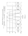
- FIG. 2 illustrates the OFDM transmission scheme using sub-carrier 1, sub-carrier 2, and sub-carrier 3. Because each OFDM symbol has finite duration in time domain, the sub-carriers overlap with each other in frequency domain. The orthogonality is maintained at the sampling frequency assuming the transmitter and the receiver has perfect frequency synchronization, as shown in FIG. 2 . In the case of frequency offset due to imperfect frequency synchronization or high mobility, the orthogonality of the sub-carriers at sampling frequencies is destroyed, resulting in inter-carrier-interference (ICI).
- ICI inter-carrier-interference
- FIG. 3 A time domain illustration of the transmitted and received OFDM symbols is shown in FIG. 3 .
- the CP portion of the received signal is often corrupted by the previous OFDM symbol.
- the received OFDM symbol without CP should only contain its own signal convoluted by the multipath fading channel.
- FFT Fast Fourier Transform
- the advantage of OFDM over other transmission schemes is its robustness to multipath fading.
- the multipath fading in time domain translates into frequency selective fading in frequency domain. With the cyclic prefix or zero prefix added, the inter-symbol-interference between adjacent OFDM symbols are avoided or largely alleviated.
- Simple equalization scheme can be used to combat frequency selection fading.
- SC-FDMA Single carrier frequency division multiple access
- SC-FDMA Single carrier frequency division multiple access
- One advantage of SC-FDMA is that the SC-FDMA signal has lower peak-to-average power ratio (PAPR) because of its inherent single carrier structure. Low PAPR normally results in high efficiency of power amplifier, which is particularly important for mobile stations in uplink transmission.
- SC-FDMA is selected as the uplink multiple access scheme in the Third Generation Partnership Project (3GPP) long term evolution (LTE).
- 3GPP Third Generation Partnership Project
- LTE Long term evolution
- An example of the transceiver chain for SC-FDMA is shown in FIG. 4 .
- the data or control signal is serial to parallel (S/P) converted by a S/P converter 181.
- Discrete Fourier transform will be applied to time-domain data or control signal by a DFT transformer 182 before the time-domain data is mapped to a set of sub-carriers by a sub-carrier mapping unit 183.
- DFT Discrete Fourier transform
- the DFT output in the frequency domain will be mapped to a set of contiguous sub-carriers.
- IFFT normally with larger size than the DFT, will be applied by an IFFT transformer 184 to transform the signal back to time domain.
- cyclic prefix (CP) will be added by a CP insertion unit 186 to the data or the control signal before the data or the control signal is transmitted to a transmission front end processing unit 187.
- the processed signal with a cyclic prefix added is often referred to as a SC-FDMA block.
- the receiver After the signal passes through a communication channel 188, e.g., a multipath fading channel in a wireless communication system, the receiver will perform receiver front end processing by a receiver front end processing unit 191, remove the CP by a CP removal unit 192, apply FFT by a FFT transformer 194 and frequency domain equalization.
- Inverse Discrete Fourier transform (IDFT) 196 will be applied after the equalized signal is de-mapped 195 in frequency domain. The output of IDFT will be passed for further time-domain processing such as demodulation and decoding.
- IDFT Inverse Discrete Fourier transform
- the downlink and uplink turbo coding chain in an Evolved Universal Terrestrial Radio Access (E-UTRA) system are show in FIG. 5 and FIG. 6 , respectively.
- E-UTRA Evolved Universal Terrestrial Radio Access
- the information bit streams a 0 , a 1 , a 2 , a 3 ,..., a A -1 are basically coming from upper layer of transport channel, which is sent to the coding chain block by block.
- this bit stream is denoted as a transport block.
- a cyclic redundancy check (CRC) may be generated for the whole transport block for the purpose of error detection for that block (step 210).
- CRC cyclic redundancy check
- the bit stream in the transport block attached with the CRC is denoted as b 0 , b 1 ,..., b B -1 .
- the transport block is segmented into multiple code blocks so that multiple coded packets can be generated, which is advantageous because of benefits such as enabling parallel processing or pipelining implementation and flexible trade off between power consumption and hardware complexity.
- the bit stream in an r -th code block having a size K r is denoted as c r 0 , c r 1 ,..., c r ( Kr-1 ) .
- the bits are then encoded using a turbo encoding process (step 214).
- the turbo encoding process of the E-UTRA system is illustrated in the FIG. 7 .
- the E-UTRA uplink system as shown in FIG. 6 is similar to the E-UTRA uplink system downlink system, except that a step of channel coding (step 230) and a step of data and control multiplexing step (step 232) need to be performed before the signal is transmitted.
- FIG. 7 schematically illustrates the structure of a turbo encoder 240.
- Turbo encoder 240 uses Parallel Concatenated Convolutional Code (PCCC) with two 8-state constituent encoders 242, 244 and one turbo code internal interleaver 246. Each of the 8-state constituent encoder is constructed with three shift registers 241. The coding rate of turbo encoder is 1/3.
- PCCC Parallel Concatenated Convolutional Code
- the initial value of shift registers 241 of first and second 8-state constituent encoders 242, 244 shall be all zeros when starting to encode the input bits.
- the bits input to turbo encoder 240 are denoted by c 0 , c 1 , c 2 , c 3 ,..., C K- 1
- the bits output from the first and second 8-state constituent encoders 242, 244 are denoted by z 0 , z 1 , z 2 , z 3 ,..., z K -1 and z 0 ⁇ , z 1 ⁇ , z 2 ⁇ , z 3 ⁇ , ... , z K - 1 ⁇ , respectively.
- the bits input to turbo code internal interleaver 246 are denoted by c 0 , c 1 ,..., c K -1 , where K is the number of input bits.
- turbo code internal interleaver 246 The bits output from turbo code internal interleaver 246 are denoted by c 0 ⁇ , c 1 ⁇ , ... , c K - 1 ⁇ , and these bits are to be input into second 8-state constituent encoder 244.
- Trellis termination is performed by taking the tail bits from the shift register feedback after all information bits are encoded. Tail bits are padded after the encoding of information bits.
- the first three tail bits shall be used to terminate the first constituent encoder (upper switch of FIG. 7 in lower position) while the second constituent encoder is disabled.
- the last three tail bits shall be used to terminate the second constituent encoder (lower switch of FIG. 7 in lower position) while the first constituent encoder is disabled.
- a quadratic permutation polynomial (QPP) internal interleaver is used for illustration.
- a codeword is formed by turbo-encoded bit stream d 0 i , d 1 i , d 2 i , d 3 i , ... , d D - 1 i .
- a Rate Matching (RM) process is performed on the turbo-encoded bit stream to genetare a transmission bit stream for each transmission (step 216).
- each retransmission bit strema may be different, depending on the RM algorithm.
- a circular buffer based rate matching scheme has been proposed to E-UTRA system design. The idea is illustrated in FIG. 8 .
- information bits are encoded by a turbo encoder 252 with a rate 1/3 turbo code, which generates a stream of systematic bits (S) 254, a stream of parity bits from the first constituent convolutional code (P1) 256, and a stream of parity bits from the second constituent convolutional code (P2) 258.
- S systematic bits
- P1 256 the first constituent convolutional code
- P2 parity bits from the second constituent convolutional code
- the parity bits are written in a buffer in the order of P 11 , P 21 , P 12 , P 22 , ... , where P 11 is the first bit of the interleaved Parity 1 bits, P 21 is the first bit of the interleaved Parity 2 bits, P 12 is the second bit of the interleaved Parity 1 bits, P 22 is the second bit of the interleaved Parity 2 bits, etc.
- the transmitter reads bits from the buffer, starting from an offset position and increasing or decreasing the bit index. If the bit index reaches a certain maximum number, the bit index is reset to the first bit in the buffer. In other words, the buffer is circular.
- the size of the circular buffer needs not necessarily be the total number of coded bits at the encoder output.
- the circular buffer size is smaller than the number of coded bits at the encoder output. This allows a simple implementation of first rate matching to reduce the requirement of retransmission buffer size.
- RM is basically part of Hybrid Automatic Repeat reQuestion (HARQ) operation.
- HARQ is widely used in communication systems to combat decoding failure and improve reliability.
- Each data packet is coded using certain forward error correction (FEC) scheme.
- FEC forward error correction
- Each subpacket may only contains a portion of the coded bits. If the transmission for subpacket k fails, as indicated by a NAK in a feedback acknowledgement channel, a retransmission subpacket, subpacket k+1, is transmitted to help the receiver decode the packet.
- the retransmission subpackets may contain different coded bits than the previous subpackets.
- the receiver may softly combine or jointly decode all the received subpackets to improve the chance of decoding. Normally, a maximum number of transmissions is configured in consideration of both reliability, packet delay, and implementation complexity.
- FIG. 9 shows an example of general HARQ operation.
- HARQ functionality is controlled by the redundancy version (RV) parameters.
- RV redundancy version
- redundancy version (RV) parameters are used to determine how much information bits are transmitted on each transmission, including the first transmission and other retransmission.
- RV redundancy version
- two types of HARQ operations can be used: Chase Combing (CC) based HARQ operation and Incremental Redundancy (IR) based HARQ operation.
- CC-based HARQ the full buffer encoded bit stream, as shown in FIG. 10 , is fully retransmitted, That is, the transmission bit stream for the 1 st transmission and the 2 nd transmission are the same.
- CC-based HARQ allows the receiver to conduct modulation symbol level combing in addition to bit level combing.
- IR-based HARQ For IR-based HARQ, only partial bit stream within a codeword are transmitted in the 1 st transmission. In the 2 nd transmission, only bit stream within a codeword are transmitted. This partial bit stream may or may not overlap with 1 st transmission bit stream, as shown in FIG. 11 .
- IR-based HARQ provide a better spectral efficiency over CC-based HARQ at the expense of additional receiver implementation complexity.
- BMP Bit Priority Mapping
- Traditional BPM refers to prioritizing the systematic bits by placing them in the high reliable bit positions of high-order constellation symbol, so the systematic bits can obtain more protection than parity bits.
- This bit mapping method is based on the principle that systematic bits are more valuable than parity bits.
- BMP is particularly critical for high order modulation such as 16-Quadrature amplitude modulation (QAM) or 64QAM. This is because the neighbor relationship in the constellation, one modulation symbol can be denoted by 4/6 binary bits and each bit in them has different reliability. For 16QAM, two bits have high reliability and anther two bits have low reliability; for 64QAM, some two bits have high reliability, some other two bits have medium reliability, and the rest two bits have low reliability.
- BMP issue is directly related to how the starting point of redundancy version of transmission is optimally chosen.
- our proposals focus on how the starting point of redundancy version of transmission is optimally determined on circular rate-matching /HARQ operation.
- Our proposal application is for turbo-coded OFDM wireless systems.
- this invention can be used for both downlink and uplink of E-UTRA systems.
- E-UTRA E-UTRA systems.
- each subframe is 1ms long, containing 14 OFDM symbols. Assume the OFDM symbols in a subframe are indexed from 0 to 13. Reference symbols (RS) for antenna 0 and 1 are located in OFDM symbol 0, 4, 7, and 11. If present, reference symbols (RS) for antennas 2 and 3 are located in OFDM symbol 2 and 8.
- the control channels including Control Channel Format Indicator (CCFI), acknowledgement channel (ACK), packet data control channel (PDCCH), are transmitted in the first one, or two, or three OFDM symbols. The number of OFDM symbols used for control channel is indicated by CCFI. For example, the control channels can occupy the first OFDM symbol, or the first two OFDM symbols, or the first three OFDM symbols.
- Data channels i.e., Physical Downlink Shared Channel (PDSCH), are transmitted in other OFDM symbols.
- PDSCH Physical Downlink Shared Channel
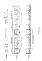
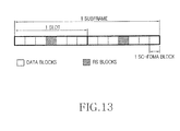
- the uplink subframe structure (for data transmissions) is shown in FIG. 13 .
- the E-UTRA uplink is a SC-FDMA based system, which is very much like an OFDMA system with some differences. Similar to an OFDM symbol, each SC-FDMA block has a cyclic prefix (CP).
- the reference signals are located at the 4-th SC-FDMA block and the 11-th SC-FDMA block with the rest of the SC-FDMA blocks carrying data.
- FIG. 13 only shows the time-domain structure of an uplink subframe. For each individual UE, its transmission may only occupy a portion of the whole bandwidth in frequency domain. And different users and control signals are multiplexed in the frequency domain via SC-FDMA.
- the circular buffer rate matching consists of the following steps:
- RV redundancy versions
- D the code block size, including information bits and tail bits.
- K the number of information bits in each code block, or the QPP interleaver size.
- R ⁇ K/32 ⁇ .
- the number of dummy bits, Y can be 4, 12, 20, and 28, depending on the information size (or QPP interleaver size) K.
- Y can be 4, 12, 20, and 28, depending on the information size (or QPP interleaver size) K.
- redundancy versions are defined in the circular buffer, with the index of the first bit in the circular buffer being 0. It is noted that in an IR-based HARQ operation with circular buffer rate matching like E-UTRA system, it is critically important to choose the starting position of each redundancy version to ensure that all codeword bits achieving approximately equal protection through proper modulation constellation rearrangement. Note that dummy bits are filled before the interleaving process, and are removed before filling the coded bits into the circular buffer.
- ⁇ (j,p) the number of bits between the starting point of redundancy version p, RV(p) and redundancy version j, RV(j).
- a method of choosing the starting position of at least one redundancy version in the circular buffer such that the number of coded bits between the starting position of a first redundancy version and the starting position of a second redundancy version is not divisible by the modulation order of a modulation scheme used for modulating data to be transmitted.
- the first redundancy version and the second redundancy version are not limited to be immediately adjacent to each other.
- the modulation order of 16-QAM is 4, and the modulation order of 64-QAM is 6.
- one implementation of this embodiment is to apply an offset to the starting position of a redundancy version defined by R ⁇ ((24 ⁇ j )+2).
- ⁇ RV ( j ) [ R ⁇ ((24 ⁇ j )+2)]-[ R ⁇ ((24 ⁇ p )+2)] is not divisible by 4 and 6 for any, or most of, two redundancy versions j and p . Note that this embodiment is applicable at both the transmitter and receiver.
- a second embodiment we propose another method of choosing the starting position of at least one redundancy version in the circular buffer based on redundancy version index j , or information size (or QPP interleaver size) K, or modulation order, or a combination of these parameters.
- K For a given modulation type and a given QPP interleaver size, K, we conduct the following algorithm to find ⁇ RV ( j ) .
- RV ( j ) is function of QPP interleaver size, which is divisible by 4, as shown in Table 1, by choosing G properly to be not divisible by 4, this would increase the occurrence that ⁇ ( j,p ) is not divisible by 4 and 6, for any, or most of, two redundancy versions j and p .
- G can choose G to be 27, or 29, or 23.
- a fourth embodiment we propose to change the circular buffer size L to a number that is not divisible by at least one modulation order, e . g ., 4 or 6.
- a modulation order e . g ., 4 or 6.
- RV j R ⁇ 24 ⁇ j + 2
- j 0 , 1 , ... , 3
- ⁇ RV ( j ) is determined by the modulation order M, the QPP interleaver size K, and redundancy version j.
- the number of dummy bits, Y can be 4, 12, 20, and 28, for a given QPP interleaver size K .
- ⁇ RV ( j ) is determined by the modulation order M, the QPP interleaver size K, and redundancy version j.
- ⁇ RV ( j ) is generated based on Table 3.
- ⁇ RV ( j ) is determined by the modulation order M, the QPP interleaver size K, redundancy version j.
- ⁇ RV ( j ) is generated based on the Table 4.
- the description of the embodiments is based on the concept of circular buffer, the actual implementation of transmitter or receiver may not implement the circular buffer as a single and separate step. Instead, the circular buffer rate matching operation may be jointed achieved with other processes such as rate matching due to buffer size limitation, sub-block interleaving, bit selection for a given redundancy version, filler bits padding / depadding, dummy bits insertion / pruning, modulation, channel interleaving, and mapping modulation symbols to physical resources, etc.
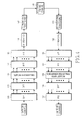
- FIG. 15 illustrates part of a transmitter chain 400 for LTE downlink shared channel (DL_SCH) and uplink shared channel (UL_SCH).
- information bits are first encoded by a channel coding unit 402, e.g., a turbo encoder.
- the encoded bits are separated into multiple sub-blocks by a bit separation unit 404.
- Each sub-block is interleaved by a respective corresponding sub-block interleaving unit 406.
- the interleaved bits are collected by a bit collection unit 408.
- a subset of bits are selected by a bit selection unit 410 and modulated by a modulation unit 412.
- the channel is interleaved by a channel interleaving unit 414 before the signal is finally transmitted.
- the embodiments described in this invention i.e., the virtual circular buffer 409, can be applied to the 'Bit Selection' step in the process that uses the value of redundancy version and/or new data indication to select the coded bits for each transmission.
- the embodiments of the inventions have applicability to the implementations if the 'Bit Selection' step is combined with other steps in the transmitter processing chain.
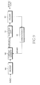
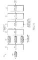
- FIG. 16 illustrates part of a receiver chain 500 for LTE DL_SCH and UL_SCH.
- the channel is first de-interleaved by channel de-interleaving unit 502.
- the data signals are de-modulated by a de-modulation unit 504 to generate a plurality of sets of de-modulated bits.
- the de-modulated bits are stored into a storing unit, e.g., a virtual circular buffer, by a bit de-selection unit 506.
- the stored bits are separated into multiple sub-blocks by a bit separation unit 508. Each sub-block is interleaved by a respective corresponding sub-block interleaving unit 510.
- the interleaved bits of the multiple sub-blocks are collected by a bit collection unit 512.
- the channel is decoded by a channel decoding unit 514 to restore the original signal.
- the embodiments described in this invention can be applied to the 'Bit De-selection' step in the process that uses the value of redundancy version and/or new data indication to put the received soft values to the correct positions in the buffer or input to the channel decoder for each transmission.
- the embodiments of the invention have applicability to the implementations if the 'Bit De-selection' step is combined with other steps in the transmitter processing chain.
Abstract
Description
- The present invention relates to methods and apparatus for improving circular buffer rate matching process in turbo-coded multiple input and multiple output (MIMO) Orthogonal Frequency Division Multiplexing (OFDM) systems.
- Evolved Universal Terrestrial Radio Access (E-UTRA) systems have been proposed and developed in a Third Generation Partnership Project Long Term Evolution (3GPP LTE) project. The E-UTRA system would be deployed over any IP network, including the Worldwide Interoperability for Microwave Access (WiMAX) network and the WiFi network, and even wired networks.
- The proposed E-UTRA system uses Orthogonal Frequency-Division Multiple Access (OFDMA) for the downlink (base station to user equipment) transmission and Single carrier frequency division multiple access (SC-FDMA) for the uplink transmission, and employs multiple input and multiple output (MIMO) with up to four antennas per station. The channel coding scheme for transport blocks is turbo coding with a contention-free quadratic permutation polynomial (QPP) turbo code internal interleaver.
- After the turbo encoding process, a codeword is formed by turbo-encoded bit stream, and a Rate Matching (RM) is performed on the turbo-encoded bit stream to generate a transmission bit stream for each transmission. In the case of retransmission, each retransmission bit stream may be different, depending on the RM algorithm.
- Notice that Rate Matching (RM) is basically part of Hybrid Automatic Repeat reQuestion (HARQ) operation. HARQ is widely used in communication systems to combat decoding failure and improve reliability. Each data packet is coded using certain forward error correction (FEC) scheme. Each subpacket may only contains a portion of the coded bits. If the transmission for subpacket k fails, as indicated by a NAK in a feedback acknowledgement channel, a retransmission subpacket, subpacket k+1, is transmitted to help the receiver decode the packet. The retransmission subpackets may contain different coded bits than the previous subpackets. The receiver may softly combine or jointly decode all the received subpackets to improve the chance of decoding. Normally, a maximum number of transmissions is configured in consideration of both reliability, packet delay, and implementation complexity.
- A contemporary HARQ operation in turbo-coded wireless systems can be performed with either incremental redundancy (IR) or chase combining. In an IR-based combining with circular buffer rate matching such as E-UTRA HARQ system, Bit Priority Mapping (BMP) issue is directly related to how the starting point of redundancy version of transmission is optimally chosen.
- It is therefore an object of the present invention to provide an improved method and apparatus for transmitting and receiving data in turbo-coded OFDM wireless systems.
- It is another object of the present invention to provide an improved method and apparatus to optimally determining the starting point of the redundancy versions for transmission in circular rate-matching /HARQ operation.
- According to one aspect of the present invention, at least one block of information bits to be transmitted are encoded to generate a plurality of coded bits, which are then segmented into a plurality of sub-blocks of coded bits. Each of the sub-blocks of coded bits is interleaved by using a certain interleaver. The interleaved coded bits of the plurality of sub-blocks are collected and written into a circular buffer having a plurality of redundancy versions in the circular buffer, with each redundancy version corresponding to a starting bit index in the circular buffer. For each transmission, a subset of bits are selected from the circular buffer by selecting a redundancy version from among the plurality of redundancy versions. The selected subset of bits are modulated by using a certain modulation scheme, and are transmitted via at least one antenna. The redundancy versions of the circular buffer being determined so that in at least one pair of redundancy versions, the number of bits between the starting point of a first redundancy version and the starting point of a second redundancy version is not divisible by at least one modulation order.
- Each of the sub-blocks of coded bits may be interleaved by using a row-column interleaver having C columns and R rows. Four redundancy versions may be determined in the circular buffer. The subset of bits may be modulated by using one of a Quadrature phase-shift keying (QPSK) modulation, a 16-Quadrature amplitude modulation (QAM) and a 64-Quadrature amplitude modulation (QAM). Then, the starting bit index of a redundancy version may be established by:

where j is the index of the redundancy version, δRV(j) is determined such that Δ'(j,p)=[R×(24×j+2)]-[R×(24×p+2)] is not divisible by 4 and 6 for at least one pair of j and p, and j = 0, 1, ... , 3, p = 0, 1, ... , 3. - When the Quadrature phase-shift keying (QPSK) modulation is used for modulating the subset of bits, δ RV (j) may be set to be zero. When the 16-Quadrature amplitude modulation (QAM) is used for modulating the subset of bits, and when Δ'(j,p)/4 is an integer number, δ RV (j) may be set to be 1, 2 or 3; and when Δ(j,p)/4 is not an integer number, δ RV (j) may be set to be zero. When the 64-Quadrature amplitude modulation (QAM) is used for modulating the subset of bits and when Δ'(j,p)/6 is an integer number, δ RV (j) may be set to be 1, 2, 3, 4 or 5; and when Δ'(j,p)
l 6 is not an integer number, δ RV (j) may be set to be zero. - Alternatively, δ RV (j) may be determined in dependence upon the number of dummy bits Y .
- Alternatively, the starting bit index of a redundancy version may be established by:

where j is the index of the redundancy version and j = 0, 1, ..., 3, and G is an integer that is not divisible by at least one of 4 and 6. - Still alternatively, a size of the circular buffer may be determined to be a number that is not divisible by at least one modulation order.
- According to another aspect of the present invention, a plurality of blocks of data bits are received via at least one antenna. The plurality of blocks of data bits are de-modulated by using a certain modulation scheme, and are then written into a circular buffer, with each block of de-modulated bits being written in accordance with a redundancy version selected from among a plurality of redundancy versions. The bits written into the circular buffer are segmented into a plurality of sub-blocks of bits. Each of the sub-blocks of bits is interleaved by using a certain interleaver. The interleaved bits are collected from the plurality of sub-blocks to generate a collected block of bits. Finally, the collected block of bits is decoded by using a certain decoding scheme. The redundancy versions of the circular being determined such that in at least one pair of redundancy versions, the number of bits between the starting point of a first redundancy version and the starting point of a second redundancy version being not divisible by at least one modulation order.
- A more complete appreciation of the invention, and many of the attendant advantages thereof, will be readily apparent as the same becomes better understood by reference to the following detailed description when considered in conjunction with the accompanying drawings in which like reference symbols indicate the same or similar components, wherein:
-
FIG. 1 is an illustration of an Orthogonal Frequency Division Multiplexing (OFDM) transceiver chain suitable for the practice of the principles of the present invention; -
FIG. 2 is two coordinate graphs of OFDM subcarriers showing amplitude as a function of frequency; -
FIG. 3 is an illustration of the transmitted and received waveforms for OFDM symbols in a time domain; -
FIG. 4 is an illustration of a single carrier frequency division multiple access transceiver chain; -
FIG. 5 schematically illustrates a coding chain for turbo-coded Evolved Universal Terrestrial Radio Access (E-UTRA) downlink systems; -
FIG. 6 schematically illustrates a coding chain for turbo-coded Evolved Universal Terrestrial Radio Access (E-UTRA) uplink systems; -
FIG. 7 schematically illustrates the structure of arate 1/3 turbo encoder; -
FIG. 8 schematically illustrates a circular buffer based rate matching (RM) operation; -
FIG. 9 schematically illustrates a Hybrid Automatic Repeat reQuestion (HARQ) operation; -
FIG. 10 schematically illustrates a chase combining (CC) based HARQ operation; -
FIG. 11 schematically illustrates a incremental redundancy (IR) based HARQ operation; -
FIG. 12 schematically illustrates a E-UTRA downlink subframe; -
FIG. 13 schematically illustrates a E-UTRA uplink subframe; -
FIG. 14 schematically illustrates redundancy version (RV) transmissions as an embodiment according to the principles of the present invention; -
FIG. 15 schematically illustrates an example of a data channel transmitter chain including rate matching; and -
FIG. 16 schematically illustrates an example of a data channel receiver chain including de-rate-matching. -
FIG. 1 illustrates an Orthogonal Frequency Division Multiplexing (OFDM) transceiver chain. In a communication system using OFDM technology, attransmitter chain 110, control signals ordata 111 is modulated bymodulator 112 into a series of modulation symbols, that are subsequently serial-to-parallel converted by Serial/Parallel (S/P)converter 113. Inverse Fast Fourier Transform (IFFT)unit 114 is used to transfer the signals from frequency domain to time domain into a plurality of OFDM symbols. Cyclic prefix (CP) or zero prefix (ZP) is added to each OFDM symbol byCP insertion unit 116 to avoid or mitigate the impact due to multipath fading. Consequently, the signal is transmitted by transmitter (Tx) frontend processing unit 117, such as an antenna (not shown), or alternatively, by fixed wire or cable. Atreceiver chain 120, assuming perfect time and frequency synchronization are achieved, the signal received by receiver (Rx) frontend processing unit 121 is processed byCP removal unit 122. Fast Fourier Transform (FFT)unit 124 transfers the received signal from time domain to frequency domain for further processing. - In an OFDM system, each OFDM symbol consists of multiple sub-carriers. Each sub-carrier within an OFDM symbol carriers a modulation symbol.
FIG. 2 illustrates the OFDM transmissionscheme using sub-carrier 1,sub-carrier 2, andsub-carrier 3. Because each OFDM symbol has finite duration in time domain, the sub-carriers overlap with each other in frequency domain. The orthogonality is maintained at the sampling frequency assuming the transmitter and the receiver has perfect frequency synchronization, as shown inFIG. 2 . In the case of frequency offset due to imperfect frequency synchronization or high mobility, the orthogonality of the sub-carriers at sampling frequencies is destroyed, resulting in inter-carrier-interference (ICI). - A time domain illustration of the transmitted and received OFDM symbols is shown in
FIG. 3 . Due to multipath fading, the CP portion of the received signal is often corrupted by the previous OFDM symbol. As long as the CP is sufficiently long, however, the received OFDM symbol without CP should only contain its own signal convoluted by the multipath fading channel. In general, a Fast Fourier Transform (FFT) is taken at the receiver side to allow further processing frequency domain. The advantage of OFDM over other transmission schemes is its robustness to multipath fading. The multipath fading in time domain translates into frequency selective fading in frequency domain. With the cyclic prefix or zero prefix added, the inter-symbol-interference between adjacent OFDM symbols are avoided or largely alleviated. Moreover, because each modulation symbol is carried over a narrow bandwidth, it experiences a single path fading. Simple equalization scheme can be used to combat frequency selection fading. - Single carrier frequency division multiple access (SC-FDMA), which utilizes single carrier modulation and frequency domain equalization is a technique that has similar performance and complexity as those of an OFDMA system. One advantage of SC-FDMA is that the SC-FDMA signal has lower peak-to-average power ratio (PAPR) because of its inherent single carrier structure. Low PAPR normally results in high efficiency of power amplifier, which is particularly important for mobile stations in uplink transmission. SC-FDMA is selected as the uplink multiple access scheme in the Third Generation Partnership Project (3GPP) long term evolution (LTE). An example of the transceiver chain for SC-FDMA is shown in
FIG. 4 . At the transmitter side, the data or control signal is serial to parallel (S/P) converted by a S/P converter 181. Discrete Fourier transform (DFT) will be applied to time-domain data or control signal by a DFT transformer 182 before the time-domain data is mapped to a set of sub-carriers by a sub-carrier mapping unit 183. To ensure low PAPR, normally the DFT output in the frequency domain will be mapped to a set of contiguous sub-carriers. Then IFFT, normally with larger size than the DFT, will be applied by an IFFT transformer 184 to transform the signal back to time domain. After parallel to serial (P/S) conversion by a P/S/ converter 185, cyclic prefix (CP) will be added by a CP insertion unit 186 to the data or the control signal before the data or the control signal is transmitted to a transmission front end processing unit 187. The processed signal with a cyclic prefix added is often referred to as a SC-FDMA block. After the signal passes through a communication channel 188, e.g., a multipath fading channel in a wireless communication system, the receiver will perform receiver front end processing by a receiver front end processing unit 191, remove the CP by a CP removal unit 192, apply FFT by a FFT transformer 194 and frequency domain equalization. Inverse Discrete Fourier transform (IDFT) 196 will be applied after the equalized signal is de-mapped 195 in frequency domain. The output of IDFT will be passed for further time-domain processing such as demodulation and decoding. - The downlink and uplink turbo coding chain in an Evolved Universal Terrestrial Radio Access (E-UTRA) system are show in
FIG. 5 andFIG. 6 , respectively. In the E-UTRA down link system as shown inFIG. 5 , the information bit streams a 0,a 1,a 2,a 3,...,a A-1 are basically coming from upper layer of transport channel, which is sent to the coding chain block by block. Typically, this bit stream is denoted as a transport block. A cyclic redundancy check (CRC) may be generated for the whole transport block for the purpose of error detection for that block (step 210). The bit stream in the transport block attached with the CRC is denoted as b 0,b 1,...,b B-1. When a transport block is large, the transport block is segmented into multiple code blocks so that multiple coded packets can be generated, which is advantageous because of benefits such as enabling parallel processing or pipelining implementation and flexible trade off between power consumption and hardware complexity. The bit stream in an r -th code block having a size Kr is denoted as c r0,c r1,...,c r(Kr-1). The bits are then encoded using a turbo encoding process (step 214). As an example, the turbo encoding process of the E-UTRA system is illustrated in theFIG. 7 . Notice that this turbo encoding process are generally used, for example, downlink physical shared channel (DL-SCH). In the DL-SCH design, one 24-bit CRC is generated for the whole transport block for the purpose of error detection for that block. The E-UTRA uplink system as shown inFIG. 6 is similar to the E-UTRA uplink system downlink system, except that a step of channel coding (step 230) and a step of data and control multiplexing step (step 232) need to be performed before the signal is transmitted. -
FIG. 7 schematically illustrates the structure of aturbo encoder 240.Turbo encoder 240 uses Parallel Concatenated Convolutional Code (PCCC) with two 8-state constituent encoders internal interleaver 246. Each of the 8-state constituent encoder is constructed with threeshift registers 241. The coding rate of turbo encoder is 1/3. - The transfer function of the 8-state constituent encoder for the PCCC is:

where :

- The initial value of
shift registers 241 of first and second 8-state constituent encoders 


for k = 0,1, 2, ..., K -1 . - If the code block to be encoded is the 0-th code block and the number of filler bits is greater than zero, i.e., F > 0, then the encoder shall set ck = 0, k = 0,...,(F-1) at its input and shall set


- The bits input to
turbo encoder 240 are denoted by c 0,c 1,c 2,c 3,...,C K-1, and the bits output from the first and second 8-state constituent encoders 
internal interleaver 246 are denoted by c 0,c 1,...,c K-1 , where K is the number of input bits. The bits output from turbo codeinternal interleaver 246 are denoted by
state constituent encoder 244. - Trellis termination is performed by taking the tail bits from the shift register feedback after all information bits are encoded. Tail bits are padded after the encoding of information bits.
- The first three tail bits shall be used to terminate the first constituent encoder (upper switch of
FIG. 7 in lower position) while the second constituent encoder is disabled. The last three tail bits shall be used to terminate the second constituent encoder (lower switch ofFIG. 7 in lower position) while the first constituent encoder is disabled. - The transmitted bits for trellis termination shall then be:


- As an example, a quadratic permutation polynomial (QPP) internal interleaver is used for illustration. The relationship between the input and output bits for a QPP internal interleaver is as follows:

where the block size K ≥ 40, and K = 8 × (4m + j), j can be chosen from the set of {1, 2, 3, 4} and m can be chosen from the set of { 1, 2, ..., 191}, and the relationship between the output index i and the input index Π(i) satisfies the following quadratic form:
where the parameters f 1 and f 2 depend on the block size K and are summarized in following Table 1.Table 1. Turbo code internal interleaver parameters i Ki f 1 f 2 i Ki f 1 f 2 i K i f 1 f 2 i Ki f 1 f 2 1 40 3 10 48 416 25 52 95 1120 67 140 142 3200 111 240 2 48 7 12 49 424 51 106 96 1152 35 72 143 3264 443 204 3 56 19 42 50 432 47 72 97 1184 19 74 144 3328 51 104 4 64 7 16 51 440 91 110 98 1216 39 76 145 3392 51 212 5 72 7 18 52 448 29 168 99 1248 19 78 146 3456 451 192 6 80 11 20 53 456 29 114 100 1280 199 240 147 3520 257 220 7 88 5 22 54 464 247 58 101 1312 21 82 148 3584 57 336 8 96 11 24 55 472 29 118 102 1344 211 252 149 3648 313 228 9 104 7 26 56 480 89 180 103 1376 21 86 150 3712 271 232 10 112 41 84 57 488 91 122 104 1408 43 88 151 3776 179 236 11 120 103 90 58 496 157 62 105 1440 149 60 152 3840 331 120 12 128 15 32 59 504 55 84 106 1472 45 92 153 3904 363 244 13 136 9 34 60 512 31 64 107 1504 49 846 154 3968 375 248 14 144 17 108 61 528 17 66 108 1536 71 48 155 4032 127 168 15 152 9 38 62 544 35 68 109 1568 13 28 156 4096 31 64 16 160 21 120 63 560 227 420 110 1600 17 80 157 4160 33 130 17 168 101 84 64 576 65 96 111 1632 25 102 158 4224 43 264 18 176 21 44 65 592 19 74 112 1664 183 104 159 4288 33 134 19 184 57 46 66 608 37 76 113 1696 55 954 160 4352 477 408 20 192 23 48 67 624 41 234 114 1728 127 96 161 4416 35 138 21 200 13 50 68 640 39 80 115 1760 27 110 162 4480 233 280 22 208 27 52 69 656 185 82 116 1792 29 112 163 4544 357 142 23 216 11 36 70 672 43 252 117 1824 29 114 164 4608 337 480 24 224 27 56 71 688 21 86 118 1856 57 116 165 4672 37 146 25 232 85 58 72 704 155 44 119 1888 45 354 166 4736 71 444 26 240 29 60 73 720 79 120 120 1920 31 120 167 4800 71 120 27 248 33 62 74 736 139 92 121 1952 59 610 168 4864 37 152 28 256 15 32 75 752 23 94 122 1984 185 124 169 4928 39 462 29 264 17 198 76 768 217 48 123 2016 113 420 170 4992 127 234 30 272 33 68 77 784 25 98 124 2048 31 64 171 5056 39 158 31 280 103 210 78 800 17 80 125 2112 17 66 172 5120 39 80 32 288 19 36 79 816 127 102 126 2176 171 136 173 5184 31 96 33 296 19 74 80 832 25 52 127 2240 209 420 174 5248 113 902 34 304 37 76 81 848 239 106 128 2304 253 216 175 5312 41 166 35 312 19 78 82 864 17 48 129 2368 367 444 176 5376 251 336 36 320 21 120 83 880 137 110 130 2432 265 456 177 5440 43 170 37 328 21 82 84 896 215 112 131 2496 181 468 178 5504 21 86 38 336 115 84 85 912 29 114 132 2560 39 80 179 5568 43 174 39 344 193 86 86 928 15 58 133 2624 27 164 180 5632 45 176 40 352 21 44 87 944 147 118 134 2688 127 504 181 5696 45 178 41 360 133 90 88 960 29 60 135 2752 143 172 182 5760 161 120 42 368 81 46 89 976 59 122 136 2816 43 88 183 5824 89 182 43 376 45 94 90 992 65 124 137 2880 29 300 184 5888 323 184 44 384 23 48 91 1008 55 84 138 2944 45 92 185 5952 47 186 45 392 243 98 92 1024 31 64 139 3008 157 188 186 6016 23 94 46 400 151 40 93 1056 17 66 140 3072 47 96 187 6080 47 190 47 408 155 102 94 1088 171 204 141 3136 13 28 188 6144 263 480 - Turning back to
FIG. 5 , after the turbo encoding process, a codeword is formed by turbo-encoded bit stream
- A circular buffer based rate matching scheme has been proposed to E-UTRA system design. The idea is illustrated in
FIG. 8 . In this example, information bits are encoded by aturbo encoder 252 with arate 1/3 turbo code, which generates a stream of systematic bits (S) 254, a stream of parity bits from the first constituent convolutional code (P1) 256, and a stream of parity bits from the second constituent convolutional code (P2) 258. Each of these three streams will be interleaved by asub-block interleaver 260. The interleavedparity bits P1 256 andparity bits P2 258 are then interlaced. In other words, the parity bits are written in a buffer in the order of P11, P21, P12, P22, ... , where P11 is the first bit of the interleavedParity 1 bits, P21 is the first bit of the interleavedParity 2 bits, P12 is the second bit of the interleavedParity 1 bits, P22 is the second bit of the interleavedParity 2 bits, etc. During the rate matching procedure, for each transmission, the transmitter reads bits from the buffer, starting from an offset position and increasing or decreasing the bit index. If the bit index reaches a certain maximum number, the bit index is reset to the first bit in the buffer. In other words, the buffer is circular. Note the size of the circular buffer needs not necessarily be the total number of coded bits at the encoder output. For example, as shown inFIG. 8 , the circular buffer size is smaller than the number of coded bits at the encoder output. This allows a simple implementation of first rate matching to reduce the requirement of retransmission buffer size. - Notice that RM is basically part of Hybrid Automatic Repeat reQuestion (HARQ) operation. HARQ is widely used in communication systems to combat decoding failure and improve reliability. Each data packet is coded using certain forward error correction (FEC) scheme. Each subpacket may only contains a portion of the coded bits. If the transmission for subpacket k fails, as indicated by a NAK in a feedback acknowledgement channel, a retransmission subpacket, subpacket k+1, is transmitted to help the receiver decode the packet. The retransmission subpackets may contain different coded bits than the previous subpackets. The receiver may softly combine or jointly decode all the received subpackets to improve the chance of decoding. Normally, a maximum number of transmissions is configured in consideration of both reliability, packet delay, and implementation complexity.
FIG. 9 shows an example of general HARQ operation. - In conjunction of rate matching process, HARQ functionality is controlled by the redundancy version (RV) parameters. The exact set of bits at the output of the hybrid ARQ functionality depends on the number of input bits, the number of output bits, RM processing, and the RV parameters.
- It is noted that redundancy version (RV) parameters are used to determine how much information bits are transmitted on each transmission, including the first transmission and other retransmission. In terms of how much redundancy information bits transmitted, two types of HARQ operations can be used: Chase Combing (CC) based HARQ operation and Incremental Redundancy (IR) based HARQ operation. For CC-based HARQ, the full buffer encoded bit stream, as shown in
FIG. 10 , is fully retransmitted, That is, the transmission bit stream for the 1st transmission and the 2nd transmission are the same. CC-based HARQ allows the receiver to conduct modulation symbol level combing in addition to bit level combing. For IR-based HARQ, only partial bit stream within a codeword are transmitted in the 1st transmission. In the 2nd transmission, only bit stream within a codeword are transmitted. This partial bit stream may or may not overlap with 1st transmission bit stream, as shown inFIG. 11 . Typically, IR-based HARQ provide a better spectral efficiency over CC-based HARQ at the expense of additional receiver implementation complexity. - Typically, CC-based or IR-based HARQ in turbo-coded systems requires that an original transmission bit stream should not be mapped into the same modulation constellation as its retransmission bit stream. This is known as Bit Priority Mapping (BMP). Traditional BPM refers to prioritizing the systematic bits by placing them in the high reliable bit positions of high-order constellation symbol, so the systematic bits can obtain more protection than parity bits. This bit mapping method is based on the principle that systematic bits are more valuable than parity bits. BMP is particularly critical for high order modulation such as 16-Quadrature amplitude modulation (QAM) or 64QAM. This is because the neighbor relationship in the constellation, one modulation symbol can be denoted by 4/6 binary bits and each bit in them has different reliability. For 16QAM, two bits have high reliability and anther two bits have low reliability; for 64QAM, some two bits have high reliability, some other two bits have medium reliability, and the rest two bits have low reliability.
- In an IR-based combining with circular buffer rate matching such as E-UTRA HARQ system, BMP issue is directly related to how the starting point of redundancy version of transmission is optimally chosen.
- In this invention, our proposals focus on how the starting point of redundancy version of transmission is optimally determined on circular rate-matching /HARQ operation. Our proposal application is for turbo-coded OFDM wireless systems.
- As an example, this invention can be used for both downlink and uplink of E-UTRA systems. Below, we briefly describe two transmission formats of downlink and uplink communications in E-UTRA systems.
- The downlink subframe structure of E-UTRA is shown in
FIG. 12 . In a typical configuration, each subframe is 1ms long, containing 14 OFDM symbols. Assume the OFDM symbols in a subframe are indexed from 0 to 13. Reference symbols (RS) forantenna OFDM symbol antennas OFDM symbol - The uplink subframe structure (for data transmissions) is shown in
FIG. 13 . Note the E-UTRA uplink is a SC-FDMA based system, which is very much like an OFDMA system with some differences. Similar to an OFDM symbol, each SC-FDMA block has a cyclic prefix (CP). For data transmissions, the reference signals are located at the 4-th SC-FDMA block and the 11-th SC-FDMA block with the rest of the SC-FDMA blocks carrying data. Note thatFIG. 13 only shows the time-domain structure of an uplink subframe. For each individual UE, its transmission may only occupy a portion of the whole bandwidth in frequency domain. And different users and control signals are multiplexed in the frequency domain via SC-FDMA. - In this invention, we propose methods and apparatus of redundancy version of retransmission for turbo-coded OFDM wireless systems to improve the reliability of the transmission and reduce the transmitter and receiver complexity.
- Aspects, features, and advantages of the invention are readily apparent from the following detailed description, simply by illustrating a number of particular embodiments and implementations, including the best mode contemplated for carrying out the invention. The invention is also capable of other and different embodiments, and its several details can be modified in various obvious respects, all without departing from the spirit and scope of the invention. Accordingly, the drawings and description are to be regarded as illustrative in nature, and not as restrictive. The invention is illustrated by way of example, and not by way of limitation, in the figures of the accompanying drawings. In the following illustrations, we use data channel in E-UTRA systems as an example. However, the technique illustrated here can certainly be used in other channel in E-UTRA systems, and other data, control, or other channels in other systems whenever applicable.
- As shown in
FIG. 14 , there are three bit streams for each code block at the turbo encoder output, namely, the systematicbit stream S 312, the firstparity stream P1 314, and the secondparity stream P2 316. The circular buffer rate matching consists of the following steps: - 1. Each of the three streams is interleaved separately by a
sub-block interleaver 318; - 2. The interleaved
systematic bits S 312 are written into a buffer in sequence, with the first bit of the interleaved systematic bit stream S at the beginning of the buffer. The interleaved P1 and P2 streams are interlaced bit by bit; and - 3. The interleaved and interlaced parity bit streams
P1 314 andP2 316 are written into the buffer in sequence, with the first bit of the stream next to the last bit of the interleaved systematic bit stream. - Four redundancy versions (RV) are defined, each of which specifies a starting bit index in the buffer. The transmitter chooses one RV for each HARQ transmission. The transmitter reads a block of coded bits from the buffer, starting from the bit index specified by a chosen RV.
- The sub-block interleaver is a row-column interleaver with the number of columns C = 32. Define D as the code block size, including information bits and tail bits. In other words, D = K + 4 where K is the number of information bits in each code block, or the QPP interleaver size. The number of rows of the sub-block interleaver is specified as R = ┌K/32┐. The operation of the interleaver can be described as follows:
- 1. Starting from the 0-th row and the 0-th column, write in row by row, i.e., increase column index first;
- 2. Fill up the R×C rectangle with dummy bits, if needed. The number of dummy bits Y = R×C-D;
- 3. Permute the column with the following pattern: 0, 16, 8, 24, 4, 20, 12, 28, 2, 18, 10, 26, 6, 22, 14, 30, 1, 17, 9, 25, 5, 21, 13, 29, 3, 19, 11, 27, 7, 23, 15, 31;
- 4. Starting from the 0-th row and the 0-th column, read out column by column, i.e., increase row index first; and
- 5. The size of circular buffer is L=3*(K+4). Note that the dummy bits are removed from circular buffer before transmission.
- It is noted that the number of dummy bits, Y, can be 4, 12, 20, and 28, depending on the information size (or QPP interleaver size) K. Four redundancy versions are defined in the circular buffer, with the index of the first bit in the circular buffer being 0. It is noted that in an IR-based HARQ operation with circular buffer rate matching like E-UTRA system, it is critically important to choose the starting position of each redundancy version to ensure that all codeword bits achieving approximately equal protection through proper modulation constellation rearrangement. Note that dummy bits are filled before the interleaving process, and are removed before filling the coded bits into the circular buffer.
- Before we further address the detail of embodiment, we define Δ(j,p) as the number of bits between the starting point of redundancy version p, RV(p) and redundancy version j, RV(j).
- In a first embodiment according to the principles of the present invention, we propose a method of choosing the starting position of at least one redundancy version in the circular buffer such that the number of coded bits between the starting position of a first redundancy version and the starting position of a second redundancy version is not divisible by the modulation order of a modulation scheme used for modulating data to be transmitted. Note that the first redundancy version and the second redundancy version are not limited to be immediately adjacent to each other. For example, the modulation order of 16-QAM is 4, and the modulation order of 64-QAM is 6. For example, one implementation of this embodiment is to apply an offset to the starting position of a redundancy version defined by R×((24×j)+2). We can choose the starting position of a j -th redundancy version as:

- For example, since 16-QAM and 64-QAM are the most frequently used higher-order-modulation schemes, we can choose δ RV (j) such that Δ'(j,p) = [R×((24×j)+2)]-[R×((24×p)+2)] is not divisible by 4 and 6 for any, or most of, two redundancy versions j and p. Note that this embodiment is applicable at both the transmitter and receiver.
- In a second embodiment according to the principles of the present invention, we propose another method of choosing the starting position of at least one redundancy version in the circular buffer based on redundancy version index j , or information size (or QPP interleaver size) K, or modulation order, or a combination of these parameters. For example, we can choose the starting position of a j -th redundancy version as RV(j) = R×((24×j)+2)+δ RV (j), for j = 0, 1, ..., 3. δ RV (j) is based on the following algorithm to ensure that Δ'(j,p)=[R×((24×j)+2)]-[R×((24×p)+2)] is not divisible by 4 and 6 for any, or most of, two redundancy versions j and p , such that the performance of transmissions with higher order modulation such as QAM 16 and QAM64 is improved. For a given modulation type and a given QPP interleaver size, K, we conduct the following algorithm to find δ RV (j).
- When QPSK modulation is used for transmission, we set δ RV (j) = 0. Note that M = 2 for QPSK modulation.
- When QAM16 modulation is used for transmission, we set δ RV (j) as follows: if Δ'(j,p)/4 is an integer number


Note that M = 4 for QAM-16 modulation, and Δ'(j,p) is defined as above. - When QAM64 modulation is used for transmission, we set δ RV (j) as follows: if Δ'(j,p)/6 is an integer number


Note that M = 4 for QAM-64 modulation, and Δ'(j, p) is defined as above. - In a third embodiment according to the principles of the present invention, we propose another method of choosing the starting position of at least one redundancy version in the circular buffer by setting the starting position of a j -th redundancy version as:

where G is not divisible by at least one modulation order, e.g., 4 or 6. Since RV(j) is function of QPP interleaver size, which is divisible by 4, as shown in Table 1, by choosing G properly to be not divisible by 4, this would increase the occurrence that Δ(j,p) is not divisible by 4 and 6, for any, or most of, two redundancy versions j and p . For example, we can choose G to be 27, or 29, or 23. Then, the corresponding redundancy versions could be respectively given as:


- In a fourth embodiment according to the principles of the present invention, we propose to change the circular buffer size L to a number that is not divisible by at least one modulation order, e.g., 4 or 6. For example, we can choose the staring position of a j -th redundancy version as:

and change the buffer size L to L-1 if L-1 is not divisible by 4 and 6. With the buffer size changed, this would increase the occurrence that Δ(j,p) is not divisible by 4 and 6, for any, or most of, two redundancy versions j and p . - In a fifth embodiment according to the principles of the present invention, we propose to choose the starting position of a j -th redundancy version as RV(j)=R×((24×j)+2)+δ RV (j), for j = 0, 1, ..., 3. δ RV (j) is determined by the modulation order M, the QPP interleaver size K, and redundancy version j. As shown above, the number of dummy bits, Y , can be 4, 12, 20, and 28, for a given QPP interleaver size K . We denote Y1=4, Y2=12, Y3=20, and Y4=28. For example, for high order modulation transmission such as QAM16, δ RV (j) may be generated based on the following table.
Table 2. Offset for RV definition δ RV (j) RV(0), j=0 RV(1), j=1 RV(2), j=2 RV(3), j=3 Y1 0 0 0 1 Y2 0 0 0 1 Y3 0 0 0 3 Y4 0 0 1 0 - In a sixth embodiment according to the principles of the present invention, we propose to choose the starting position of a j -th redundancy version as RV(j)=R×((24×j)+2)+δ RV (j), for j = 0, 1, ..., 3. δ RV (j) is determined by the modulation order M, the QPP interleaver size K, and redundancy version j. For example, for high order modulation transmission such as QAM16 and QAM 64, δ RV (j) is generated based on Table 3. Note that there are totally 188 QPP interleaver size, i is the QPP interleaver size index =1,2,3, ...187,188, and i is determined in dependence upon the QPP interleaver size K based on Table 1. Also note that δ RV (j)= 0 for j = 0.
Table 3. Offset for RV definition δ RV (j) i j=1 j=2 j=3 i j=1 j=2 j=3 i j=1 j=2 j=3 i j=1 j=2 j=3 1 0 1 0 48 3 1 4 95 3 1 4 142 3 1 4 2 0 0 3 49 0 1 0 96 3 1 4 143 3 1 4 3 0 5 4 50 0 0 3 97 3 1 4 144 3 1 4 4 3 1 4 51 0 5 4 98 3 1 4 145 3 1 4 5 0 1 0 52 3 1 4 99 3 1 4 146 3 1 4 6 0 0 3 53 0 1 0 100 3 1 4 147 3 1 4 7 0 5 4 54 0 0 3 101 3 1 4 148 3 1 4 8 3 1 4 55 0 5 4 102 3 1 4 149 3 1 4 9 0 1 0 56 3 1 4 103 3 1 4 150 3 1 4 10 0 0 3 57 0 1 0 104 3 1 4 151 3 1 4 11 0 5 4 58 0 0 3 105 3 1 4 152 3 1 4 12 3 1 4 59 0 5 4 106 3 1 4 153 3 1 4 13 0 1 0 60 3 1 4 107 3 1 4 154 3 1 4 14 0 0 3 61 0 0 3 108 3 1 4 155 3 1 4 15 0 5 4 62 3 1 4 109 3 1 4 156 3 1 4 16 3 1 4 63 0 0 3 110 3 1 4 157 3 1 4 17 0 1 0 64 3 1 4 111 3 1 4 158 3 1 4 18 0 0 3 65 0 0 3 112 3 1 4 159 3 1 4 19 0 5 4 66 3 1 4 113 3 1 4 160 3 1 4 20 3 1 4 67 0 0 3 114 3 1 4 161 3 1 4 21 0 1 0 68 3 1 4 115 3 1 4 162 3 1 4 22 0 0 3 69 0 0 3 116 3 1 4 163 3 1 4 23 0 5 4 70 3 1 4 117 3 1 4 164 3 1 4 24 3 1 4 71 0 0 3 118 3 1 4 165 3 1 4 25 0 1 0 72 3 1 4 119 3 1 4 166 3 1 4 26 0 0 3 73 0 0 3 120 3 1 4 167 3 1 4 27 0 5 4 74 3 1 4 121 3 1 4 168 3 1 4 28 3 1 4 75 0 0 3 122 3 1 4 169 3 1 4 29 0 1 0 76 3 1 4 123 3 1 4 170 3 1 4 30 0 0 3 77 0 0 3 124 3 1 4 171 3 1 4 31 0 5 4 78 3 1 4 125 3 1 4 172 3 1 4 32 3 1 4 79 0 0 3 126 3 1 4 173 3 1 4 33 0 1 0 80 3 1 4 127 3 1 4 174 3 1 4 34 0 0 3 81 0 0 3 128 3 1 4 175 3 1 4 35 0 5 4 82 3 1 4 129 3 1 4 176 3 1 4 36 3 1 4 83 0 0 3 130 3 1 4 177 3 1 4 37 0 1 0 84 3 1 4 131 3 1 4 178 3 1 4 38 0 0 3 85 0 0 3 132 3 1 4 179 3 1 4 39 0 5 4 86 3 1 4 133 3 1 4 180 3 1 4 40 3 1 4 87 0 0 3 134 3 1 4 181 3 1 4 41 0 1 0 88 3 1 4 135 3 1 4 182 3 1 4 42 0 0 3 89 0 0 3 136 3 1 4 183 3 1 4 43 0 5 4 90 3 1 4 137 3 1 4 184 3 1 4 44 3 1 4 91 0 0 3 138 3 1 4 185 3 1 4 45 0 1 0 92 3 1 4 139 3 1 4 186 3 1 4 46 0 0 3 93 3 1 4 140 3 1 4 187 3 1 4 47 0 5 4 94 3 1 4 141 3 1 4 188 3 1 4 - In a seventh embodiment according to the principles of the present invention, we propose to choose the starting position of a j -th redundancy version as RV(j)=R×((28×j)+2)+δ RV (j) for j = 0, 1, ..., 3. δ RV (j) is determined by the modulation order M, the QPP interleaver size K, redundancy version j. For example, for high order modulation transmission such as QAM16 and QAM 64, δ RV (j) is generated based on the Table 4. Note that there are totally 188 QPP interleaver size, i is the QPP interleaver size index =1,2,3, ...187,188, and i is determined in dependence upon the QPP interleaver size K based on Table 1. Also note that δ RV (j)=0 for j=0.
Table 4. Offset for RV definition δ RV (j) i j=1 j=2 j=3 I j=1 j=2 j=3 i j=1 j=2 j=3 i j=1 j=2 j=3 1 0 1 3 48 0 5 0 95 0 0 4 142 0 5 0 2 0 5 3 49 0 1 3 96 3 1 0 143 3 1 0 3 0 1 1 50 0 5 3 97 0 5 0 144 0 0 4 4 0 0 4 51 0 1 1 98 0 0 4 145 0 5 0 5 0 2 2 52 0 0 4 99 3 1 0 146 3 1 0 6 1 2 1 53 0 2 2 100 0 5 0 147 0 0 4 7 0 2 0 54 1 2 1 101 0 0 4 148 0 5 0 8 3 1 0 55 0 2 0 102 3 1 0 149 3 1 0 9 0 1 3 56 3 1 0 103 0 5 0 150 0 0 4 10 0 1 3 57 0 1 3 104 0 0 4 151 0 5 0 11 0 1 1 58 0 1 3 105 3 1 0 152 3 1 0 12 0 5 0 59 0 1 1 106 0 5 0 153 0 0 4 13 0 1 3 60 0 5 0 107 0 0 4 154 0 5 0 14 0 5 3 61 0 5 3 108 3 1 0 155 3 1 0 15 0 1 1 62 0 0 4 109 0 5 0 156 0 0 4 16 0 0 4 63 1 2 1 110 0 0 4 157 0 5 0 17 0 2 2 64 3 1 0 111 3 1 0 158 3 1 0 18 1 2 1 65 0 1 3 112 0 5 0 159 0 0 4 19 0 2 0 66 0 5 0 113 0 0 4 160 0 5 0 20 3 1 0 67 0 5 3 114 3 1 0 161 3 1 0 21 0 1 3 68 0 0 4 115 0 5 0 162 0 0 4 22 0 1 3 69 1 2 1 116 0 0 4 163 0 5 0 23 0 1 1 70 3 1 0 117 3 1 0 164 3 1 0 24 0 5 0 71 0 1 3 118 0 5 0 165 0 0 4 25 0 1 3 72 0 5 0 119 0 0 4 166 0 5 0 26 0 5 3 73 0 5 3 120 3 1 0 167 3 1 0 27 0 1 1 74 0 0 4 121 0 5 0 168 0 0 4 28 0 0 4 75 1 2 1 122 0 0 4 169 0 5 0 29 0 2 2 76 3 1 0 123 3 1 0 170 3 1 0 30 1 2 1 77 0 1 3 124 0 5 0 171 0 0 4 31 0 2 0 78 0 5 0 125 3 1 0 172 0 5 0 32 3 1 0 79 0 5 3 126 0 0 4 173 3 1 0 33 0 1 3 80 0 0 4 127 0 5 0 174 0 0 4 34 0 1 3 81 1 2 1 128 3 1 0 175 0 5 0 35 0 1 1 82 3 1 0 129 0 0 4 176 3 1 0 36 0 5 0 83 0 1 3 130 0 5 0 177 0 0 4 37 0 1 3 84 0 5 0 131 3 1 0 178 0 5 0 38 0 5 3 85 0 5 3 132 0 0 4 179 3 1 0 39 0 1 1 86 0 0 4 133 0 5 0 180 0 0 4 40 0 0 4 87 1 2 1 134 3 1 0 181 0 5 0 41 0 2 2 88 3 1 0 135 0 0 4 182 3 1 0 42 1 2 1 89 0 1 3 136 0 5 0 183 0 0 4 43 0 2 0 90 0 5 0 137 3 1 0 184 0 5 0 44 3 1 0 91 0 5 3 138 0 0 4 185 3 1 0 45 0 1 3 92 0 0 4 139 0 5 0 186 0 0 4 46 0 1 3 93 3 1 0 140 3 1 0 187 0 5 0 47 0 1 1 94 0 5 0 141 0 0 4 188 3 1 0 - Note that although the description of the embodiments is based on the concept of circular buffer, the actual implementation of transmitter or receiver may not implement the circular buffer as a single and separate step. Instead, the circular buffer rate matching operation may be jointed achieved with other processes such as rate matching due to buffer size limitation, sub-block interleaving, bit selection for a given redundancy version, filler bits padding / depadding, dummy bits insertion / pruning, modulation, channel interleaving, and mapping modulation symbols to physical resources, etc.
-
FIG. 15 illustrates part of atransmitter chain 400 for LTE downlink shared channel (DL_SCH) and uplink shared channel (UL_SCH). As shown inFIG. 15 , information bits are first encoded by achannel coding unit 402, e.g., a turbo encoder. The encoded bits are separated into multiple sub-blocks by abit separation unit 404. Each sub-block is interleaved by a respective correspondingsub-block interleaving unit 406. The interleaved bits are collected by abit collection unit 408. Then, for each transmission, a subset of bits are selected by abit selection unit 410 and modulated by amodulation unit 412. The channel is interleaved by achannel interleaving unit 414 before the signal is finally transmitted. The embodiments described in this invention, i.e., the virtualcircular buffer 409, can be applied to the 'Bit Selection' step in the process that uses the value of redundancy version and/or new data indication to select the coded bits for each transmission. Clearly, it is recognized by one of ordinary skill in the art that the embodiments of the inventions have applicability to the implementations if the 'Bit Selection' step is combined with other steps in the transmitter processing chain. - Similarly,
FIG. 16 illustrates part of areceiver chain 500 for LTE DL_SCH and UL_SCH. As shown inFIG. 16 , when data signals are received at a receiver, the channel is first de-interleaved bychannel de-interleaving unit 502. Then, the data signals are de-modulated by ade-modulation unit 504 to generate a plurality of sets of de-modulated bits. The de-modulated bits are stored into a storing unit, e.g., a virtual circular buffer, by a bitde-selection unit 506. Then, the stored bits are separated into multiple sub-blocks by abit separation unit 508. Each sub-block is interleaved by a respective correspondingsub-block interleaving unit 510. The interleaved bits of the multiple sub-blocks are collected by abit collection unit 512. Finally, the channel is decoded by achannel decoding unit 514 to restore the original signal. The embodiments described in this invention can be applied to the 'Bit De-selection' step in the process that uses the value of redundancy version and/or new data indication to put the received soft values to the correct positions in the buffer or input to the channel decoder for each transmission. Clearly, it is recognized by one of ordinary skill in the art that the embodiments of the invention have applicability to the implementations if the 'Bit De-selection' step is combined with other steps in the transmitter processing chain. - While the present invention has been shown and described in connection with the preferred embodiments, it will be apparent to those skilled in the art that modifications and variations can be made without departing from the spirit and scope of the invention as defined by the appended claims
Claims (24)
- A method for transmitting data, the method comprising the steps of:encoding at least one block of information bits to be transmitted to generate a plurality of coded bits;segmenting the plurality of coded bits into a plurality of sub-blocks of coded bits;interleaving each of the sub-blocks of coded bits by using a certain interleaver;collecting the interleaved coded bits from the plurality of sub-blocks and writing the collected bits into a circular buffer;determining a plurality of redundancy versions in the circular buffer, with each redundancy version corresponding to a starting bit index in the circular buffer;selecting a subset of bits in the circular buffer by selecting a redundancy version from among the plurality of redundancy version;modulating the subset of bits by using a certain modulation scheme; andtransmitting the modulated bits via at least one antenna, with, in at least one pair of redundancy versions, the number of bits between the starting point of a first redundancy version and the starting point of a second redundancy version being not divisible by the modulation order of the certain modulation scheme.
- The method of claim 1, comprised of:determining four redundancy versions in the circular buffer; and modulating the subset of bits by using one of a Quadrature phase-shift keying (QPSK) modulation, a 16-Quadrature amplitude modulation (QAM) and a 64-Quadrature amplitude modulation (QAM), with the starting bit index of a redundancy version being established by:where j is the index of the redundancy version, R=┌K/32┐, K is the size of the certain interleaver, δ RV (j) is determined such that Δ'(j,p)=[R×((24×j)+2)]-[R×((24×p)+2)] is not divisible by 4 and 6 for at least one pair of j and p , and j = 0, 1, ..., 3, p = 0, 1, ... , 3.

- The method of claim 1, comprised of:determining four redundancy versions in the circular buffer; and modulating the subset of bits by using one of a Quadrature phase-shift keying (QPSK) modulation, a 16-Quadrature amplitude modulation (QAM) and a 64-Quadrature amplitude modulation (QAM), with the starting bit index of a redundancy version being established by:where j is the index of the redundancy version, R=┌K/32┐, K is the size of the certain interleaver, δ RV (j) is determined in dependence upon Δ'(j,p)=[R×((24×j)+2)]-[R×((24×p)+2)] for at least one pair of j and p, and j = 0, 1, ..., 3, p = 0, 1, ..., 3, with:
 when the Quadrature phase-shift keying (QPSK) modulation is used for modulating the subset of bits, δ RV (j) being set to be zero;when the 16-Quadrature amplitude modulation (QAM) is used for modulating the subset of bits:when Δ'(j,p)/4 is an integer number, δ RV (j) being an integer selected from a set {1, 2, 3}; andwhen Δ'(j,p)/4 is not an integer number, δ RV (j) being set to be zero; andwhen the 64-Quadrature amplitude modulation (QAM) is used for modulating the subset of bits:when Δ'(j,p)/6 is an integer number, δ RV (j) being an integer selected from a set {1,2, 3, 4, 5};; andwhen Δ'(j,p)/6 is not an integer number, δ RV (j) being set to be zero.
 - The method of claim 1, comprised of:determining four redundancy versions in the circular buffer; and modulating the subset of bits by using one of a Quadrature phase-shift keying (QPSK) modulation, a 16-Quadrature amplitude modulation (QAM) and a 64-Quadrature amplitude modulation (QAM), with the starting bit index of a redundancy version being established by:where j is the index of the redundancy version and j = 0, 1, ..., 3, R=┌K/32┐, K is the size of the certain interleaver, and G is an integer that is not divisible by at least one of 4 and 6.

- The method of claim 1, comprised of determining a size of the circular buffer, with the size L being a number that is not divisible by at least one modulation order.
- The method of claim 1, comprised of interleaving each of the sub-blocks of coded bits by using a row-column interleaver, and for each sub-block:writing the sub-block of coded bits into the row-column interleaver in a row-by-row manner by starting from the first row and the first column, with the row-column interleaver having C columns and R rows, and the number of coded bits in the sub-block being D ;when the row-column interleaver is not filled up by the coded bits in the sub-block, filling up the row-column interleaver with dummy bits, with the number of dummy bits being Y = R × C - D ;permuting the columns in the row-column interleaver by using a certain pattern;reading the bits from the row-column interleaver in a column-by-column manner by staring from the first row and the first column; andremoving the dummy bits from the bits that are read from the row-column interleaver.
- The method of claim 6, comprised of:determining four redundancy versions in the circular buffer; and modulating the subset of bits by using one of a Quadrature phase-shift keying (QPSK) modulation, a 16-Quadrature amplitude modulation (QAM) and a 64-Quadrature amplitude modulation (QAM), with the starting bit index of a redundancy version being established by:where j is the index of the redundancy version and j = 0, 1, ..., 3, and δ RV (j) is determined in dependence upon the number of dummy bits Y.

- The method of claim 7, comprised of the number of dummy bits Y being one of 4, 12, 20 and 28, and δ RV (j) being determined based on the following table:
RV(0), j=0 RV(1), j=1 RV(2), j=2 RV(3), j=3 Y1 0 0 0 1 Y2 0 0 0 1 Y3 0 0 0 3 Y4 0 0 1 0 - The method of claim 1, comprised of:determining four redundancy versions in the circular buffer; modulating the subset of bits by using one of a Quadrature phase-shift keying (QPSK) modulation, a 16-Quadrature amplitude modulation (QAM) and a 64-Quadrature amplitude modulation (QAM), with the starting bit index of a redundancy version being established by:where j is the index of the redundancy version and j=0, 1, ...,3, R=┌K/32┐, K is the size of the certain interleaver, δ RV (j) is determined in dependence upon j and the size of the quadratic permutation polynomial (QPP) interleaver, and δ RV (j)= 0 for j = 0, and δ RV (j) is determined based upon the following table for j= 1, 2, 3:

i j=1 j=2 j=3 i j=1 j=2 j=3 i j=1 j=2 j=3 i j=1 j=2 j=3 1 0 1 0 48 3 1 4 95 3 1 4 142 3 1 4 2 0 0 3 49 0 1 0 96 3 1 4 143 3 1 4 3 0 5 4 50 0 0 3 97 3 1 4 144 3 1 4 4 3 1 4 51 0 5 4 98 3 1 4 145 3 1 4 5 0 1 0 52 3 1 4 99 3 1 4 146 3 1 4 6 0 0 3 53 0 1 0 100 3 1 4 147 3 1 4 7 0 5 4 54 0 0 3 101 3 1 4 148 3 1 4 8 3 1 4 55 0 5 4 102 3 1 4 149 3 1 4 9 0 1 0 56 3 1 4 103 3 1 4 150 3 1 4 10 0 0 3 57 0 1 0 104 3 1 4 151 3 1 4 11 0 5 4 58 0 0 3 105 3 1 4 152 3 1 4 12 3 1 4 59 0 5 4 106 3 1 4 153 3 1 4 13 0 1 0 60 3 1 4 107 3 1 4 154 3 1 4 14 0 0 3 61 0 0 3 108 3 1 4 155 3 1 4 15 0 5 4 62 3 1 4 109 3 1 4 156 3 1 4 16 3 1 4 63 0 0 3 110 3 1 4 157 3 1 4 17 0 1 0 64 3 1 4 111 3 1 4 158 3 1 4 18 0 0 3 65 0 0 3 112 3 1 4 159 3 1 4 19 0 5 4 66 3 1 4 113 3 1 4 160 3 1 4 20 3 1 4 67 0 0 3 114 3 1 4 161 3 1 4 21 0 1 0 68 3 1 4 115 3 1 4 162 3 1 4 22 0 0 3 69 0 0 3 116 3 1 4 163 3 1 4 23 0 5 4 70 3 1 4 117 3 1 4 164 3 1 4 24 3 1 4 71 0 0 3 118 3 1 4 165 3 1 4 25 0 1 0 72 3 1 4 119 3 1 4 166 3 1 4 26 0 0 3 73 0 0 3 120 3 1 4 167 3 1 4 27 0 5 4 74 3 1 4 121 3 1 4 168 3 1 4 28 3 1 4 75 0 0 3 122 3 1 4 169 3 1 4 29 0 1 0 76 3 1 4 123 3 1 4 170 3 1 4 30 0 0 3 77 0 0 3 124 3 1 4 171 3 1 4 31 0 5 4 78 3 1 4 125 3 1 4 172 3 1 4 32 3 1 4 79 0 0 3 126 3 1 4 173 3 1 4 33 0 1 0 80 3 1 4 127 3 1 4 174 3 1 4 34 0 0 3 81 0 0 3 128 3 1 4 175 3 1 4 35 0 5 4 82 3 1 4 129 3 1 4 176 3 1 4 36 3 1 4 83 0 0 3 130 3 1 4 177 3 1 4 37 0 1 0 84 3 1 4 131 3 1 4 178 3 1 4 38 0 0 3 85 0 0 3 132 3 1 4 179 3 1 4 39 0 5 4 86 3 1 4 133 3 1 4 180 3 1 4 40 3 1 4 87 0 0 3 134 3 1 4 181 3 1 4 41 0 1 0 88 3 1 4 135 3 1 4 182 3 1 4 42 0 0 3 89 0 0 3 136 3 1 4 183 3 1 4 43 0 5 4 90 3 1 4 137 3 1 4 184 3 1 4 44 3 1 4 91 0 0 3 138 3 1 4 185 3 1 4 45 0 1 0 92 3 1 4 139 3 1 4 186 3 1 4 46 0 0 3 93 3 1 4 140 3 1 4 187 3 1 4 47 0 5 4 94 3 1 4 141 3 1 4 188 3 1 4 i Ki i Ki i Ki i Ki 1 40 48 416 95 1120 142 3200 2 48 49 424 96 1152 143 3264 3 56 50 432 97 1184 144 3328 4 64 51 440 98 1216 145 3392 5 72 52 448 99 1248 146 3456 6 80 53 456 100 1280 147 3520 7 88 54 464 101 1312 148 3584 8 96 55 472 102 1344 149 3648 9 104 56 480 103 1376 150 3712 10 112 57 488 104 1408 151 3776 11 120 58 496 105 1440 152 3840 12 128 59 504 106 1472 153 3904 13 136 60 512 107 1504 154 3968 14 144 61 528 108 1536 155 4032 15 152 62 544 109 1568 156 4096 16 160 63 560 110 1600 157 4160 17 168 64 576 111 1632 158 4224 18 176 65 592 112 1664 159 4288 19 184 66 608 113 1696 160 4352 20 192 67 624 114 1728 161 4416 21 200 68 640 115 1760 162 4480 22 208 69 656 116 1792 163 4544 23 216 70 672 117 1824 164 4608 24 224 71 688 118 1856 165 4672 25 232 72 704 119 1888 166 4736 26 240 73 720 120 1920 167 4800 27 248 74 736 121 1952 168 4864 28 256 75 752 122 1984 169 4928 29 264 76 768 123 2016 170 4992 30 272 77 784 124 2048 171 5056 31 280 78 800 125 2112 172 5120 32 288 79 816 126 2176 173 5184 33 296 80 832 127 2240 174 5248 34 304 81 848 128 2304 175 5312 35 312 82 864 129 2368 176 5376 36 320 83 880 130 2432 177 5440 37 328 84 896 131 2496 178 5504 38 336 85 912 132 2560 179 5568 39 344 86 928 133 2624 180 5632 40 352 87 944 134 2688 181 5696 41 360 88 960 135 2752 182 5760 42 368 89 976 136 2816 183 5824 43 376 90 992 137 2880 184 5888 44 384 91 1008 138 2944 185 5952 45 392 92 1024 139 3008 186 6016 46 400 93 1056 140 3072 187 6080 47 408 94 1088 141 3136 188 6144 - The method of claim 1, comprised of:determining four redundancy versions in the circular buffer; modulating the subset of bits by using one of a Quadrature phase-shift keying (QPSK) modulation, a 16-Quadrature amplitude modulation (QAM) and a 64-Quadrature amplitude modulation (QAM), with the starting bit index of a redundancy version being established by:where j is the index of the redundancy version and j=0, 1 , ... , 3, R = ┌K/32┐, K is the size of the certain interleaver, δ RV (j) is determined in dependence upon j and the size of the quadratic permutation polynomial (QPP) interleaver, and δ RV (j) = 0 for j = 0, and δ RV (j) is determined based upon the following table for j=1, 2, 3 :

i j=1 j=2 j=3 i j=1 j=2 j=3 i j=1 j=2 j=3 i j=1 j=2 j=3 1 0 1 3 48 0 5 0 95 0 0 4 142 0 5 0 2 0 5 3 49 0 1 3 96 3 1 0 143 3 1 0 3 0 1 1 50 0 5 3 97 0 5 0 144 0 0 4 4 0 0 4 51 0 1 1 98 0 0 4 145 0 5 0 5 0 2 2 52 0 0 4 99 3 1 0 146 3 1 0 6 1 2 1 53 0 2 2 100 0 5 0 147 0 0 4 7 0 2 0 54 1 2 1 101 0 0 4 148 0 5 0 8 3 1 0 55 0 2 0 102 3 1 0 149 3 1 0 9 0 1 3 56 3 1 0 103 0 5 0 150 0 0 4 10 0 1 3 57 0 1 3 104 0 0 4 151 0 5 0 11 0 1 1 58 0 1 3 105 3 1 0 152 3 1 0 12 0 5 0 59 0 1 1 106 0 5 0 153 0 0 4 13 0 1 3 60 0 5 0 107 0 0 4 154 0 5 0 14 0 5 3 61 0 5 3 108 3 1 0 155 3 1 0 15 0 1 1 62 0 0 4 109 0 5 0 156 0 0 4 16 0 0 4 63 1 2 1 110 0 0 4 157 0 5 0 17 0 2 2 64 3 1 0 111 3 1 0 158 3 1 0 18 1 2 1 65 0 1 3 112 0 5 0 159 0 0 4 19 0 2 0 66 0 5 0 113 0 0 4 160 0 5 0 20 3 1 0 67 0 5 3 114 3 1 0 161 3 1 0 21 0 1 3 68 0 0 4 115 0 5 0 162 0 0 4 22 0 1 3 69 1 2 1 116 0 0 4 163 0 5 0 23 0 1 1 70 3 1 0 117 3 1 0 164 3 1 0 24 0 5 0 71 0 1 3 118 0 5 0 165 0 0 4 25 0 1 3 72 0 5 0 119 0 0 4 166 0 5 0 26 0 5 3 73 0 5 3 120 3 1 0 167 3 1 0 27 0 1 1 74 0 0 4 121 0 5 0 168 0 0 4 28 0 0 4 75 1 2 1 122 0 0 4 169 0 5 0 29 0 2 2 76 3 1 0 123 3 1 0 170 3 1 0 30 1 2 1 77 0 1 3 124 0 5 0 171 0 0 4 31 0 2 0 78 0 5 0 125 3 1 0 172 0 5 0 32 3 1 0 79 0 5 3 126 0 0 4 173 3 1 0 33 0 1 3 80 0 0 4 127 0 5 0 174 0 0 4 34 0 1 3 81 1 2 1 128 3 1 0 175 0 5 0 35 0 1 1 82 3 1 0 129 0 0 4 176 3 1 0 36 0 5 0 83 0 1 3 130 0 5 0 177 0 0 4 37 0 1 3 84 0 5 0 131 3 1 0 178 0 5 0 38 0 5 3 85 0 5 3 132 0 0 4 179 3 1 0 39 0 1 1 86 0 0 4 133 0 5 0 180 0 0 4 40 0 0 4 87 1 2 1 134 3 1 0 181 0 5 0 41 0 2 2 88 3 1 0 135 0 0 4 182 3 1 0 42 1 2 1 89 0 1 3 136 0 5 0 183 0 0 4 43 0 2 0 90 0 5 0 137 3 1 0 184 0 5 0 44 3 1 0 91 0 5 3 138 0 0 4 185 3 1 0 45 0 1 3 92 0 0 4 139 0 5 0 186 0 0 4 46 0 1 3 93 3 1 0 140 3 1 0 187 0 5 0 47 0 1 1 94 0 5 0 141 0 0 4 188 3 1 0 I Ki i Ki i Ki i Ki 1 40 48 416 95 1120 142 3200 2 48 49 424 96 1152 143 3264 3 56 50 432 97 1184 144 3328 4 64 51 440 98 1216 145 3392 5 72 52 448 99 1248 146 3456 6 80 53 456 100 1280 147 3520 7 88 54 464 101 1312 148 3584 8 96 55 472 102 1344 149 3648 9 104 56 480 103 1376 150 3712 10 112 57 488 104 1408 151 3776 11 120 58 496 105 1440 152 3840 12 128 59 504 106 1472 153 3904 13 136 60 512 107 1504 154 3968 14 144 61 528 108 1536 155 4032 15 152 62 544 109 1568 156 4096 16 160 63 560 110 1600 157 4160 17 168 64 576 111 1632 158 4224 18 176 65 592 112 1664 159 4288 19 184 66 608 113 1696 160 4352 20 192 67 624 114 1728 161 4416 21 200 68 640 115 1760 162 4480 22 208 69 656 116 1792 163 4544 23 216 70 672 117 1824 164 4608 24 224 71 688 118 1856 165 4672 25 232 72 704 119 1888 166 4736 26 240 73 720 120 1920 167 4800 27 248 74 736 121 1952 168 4864 28 256 75 752 122 1984 169 4928 29 264 76 768 123 2016 170 4992 30 272 77 784 124 2048 171 5056 31 280 78 800 125 2112 172 5120 32 288 79 816 126 2176 173 5184 33 296 80 832 127 2240 174 5248 34 304 81 848 128 2304 175 5312 35 312 82 864 129 2368 176 5376 36 320 83 880 130 2432 177 5440 37 328 84 896 131 2496 178 5504 38 336 85 912 132 2560 179 5568 39 344 86 928 133 2624 180 5632 40 352 87 944 134 2688 181 5696 41 360 88 960 135 2752 182 5760 42 368 89 976 136 2816 183 5824 43 376 90 992 137 2880 184 5888 44 384 91 1008 138 2944 185 5952 45 392 92 1024 139 3008 186 6016 46 400 93 1056 140 3072 187 6080 47 408 94 1088 141 3136 188 6144 - The method of claim 1, comprised of interleaving each of the sub-blocks of coded bits by using a quadratic permutation polynomial (QPP) interleaver.
- A method for receiving data, the method comprising the steps of:receiving a plurality of blocks of data bits via at least one antenna;de-modulating the plurality of blocks of data bits by using a certain modulation scheme;determining a plurality of redundancy versions in a circular buffer, with each redundancy version corresponding to a starting bit index in the circular buffer, and in at least one pair of redundancy versions, the number of bits between the starting point of a first redundancy version and the starting point of a second redundancy version being not divisible by the modulation order of the certain modulation scheme;writing the plurality of blocks of de-modulated bits into the circular buffer, with each block of de-modulated bits being written in accordance with a redundancy version selected from among the plurality of redundancy versions;segmenting the bits written into the circular buffer into a plurality of sub-blocks of bits;interleaving each of the sub-blocks of bits by using a certain interleaver;collecting the interleaved bits from the plurality of sub-blocks to generate a collected block of bits; anddecoding the collected block of bits by using a certain decoding scheme.
- The method of claim 12, comprised of:de-modulating the plurality of blocks of data bits by using one of a Quadrature phase-shift keying (QPSK) modulation, a 16-Quadrature amplitude modulation (QAM) and a 64-Quadrature amplitude modulation (QAM); anddetermining four redundancy versions in the circular buffer, with the starting bit index of a redundancy version being established by:where j is the index of the redundancy version, R =┌K/32┐, K is the size of the certain interleaver, δ RV (j) is determined such that Δ'(j,p)=[R×((24×j)+2)]-[R×((24×p)+2)] is not divisible by 4 and 6 for at least one pair of j and p, and j = 0, 1, ... , 3, p = 0,1, ..., 3.

- The method of claim 12, comprised of:de-modulating the subset of bits by using one of a Quadrature phase-shift keying (QPSK) modulation, a 16-Quadrature amplitude modulation (QAM) and a 64-Quadrature amplitude modulation (QAM); anddetermining four redundancy versions in the circular buffer, with the starting bit index of a redundancy version being established by:

where j is the index of the redundancy version, R=┌K/32┐, K is the size of the certain interleaver, δ RV (j) is determined in dependence upon Δ'(j,p) and Δ'(j,p)=[R×((24×j)+2)]-[R×((24×p)+2)] for at least one pair of j and p , and j = 0, 1, ..., 3, p = 0, 1, ..., 3, with:when the Quadrature phase-shift keying (QPSK) modulation is used for de-modulating the plurality of blocks of data bits, δ RV (j) being set to be zero;when the 16-Quadrature amplitude modulation (QAM) is used for de-modulating the plurality of blocks of data bits:when Δ'(j,p)/4 is an integer number, δ RV (j) being an integer selected from a set {1, 2, 3 } ; andwhen Δ'(j,p)/4 is not an integer number, δ RV (j) being set to be zero; andwhen the 64-Quadrature amplitude modulation (QAM) is used for de-modulating the plurality of blocks of data bits:when Δ'(j,p)/6 is an integer number, δ RV (j) being an integer selected fromaset{1,2,3,4,5};andwhen Δ'(j,p)/6 is not an integer number, δ RV (j) being set to be zero. - The method of claim 12, comprised of:de-modulating the plurality of blocks of data bits by using one of a Quadrature phase-shift keying (QPSK) modulation, a 16-Quadrature amplitude modulation (QAM) and a 64-Quadrature amplitude modulation (QAM); anddetermining four redundancy versions in the circular buffer, with the starting bit index of a redundancy version being established by:where j is the index of the redundancy version and j = 0, 1, ..., 3, R=┌K/32┐, K is the size of the certain interleaver, and G is an integer that is not divisible by at least one of 4 and 6.

- The method of claim 12, comprised of determining a size of the circular buffer, with the size L being a number that is not divisible by at least one modulation order.
- The method of claim 12, comprised of interleaving each of the sub-blocks of bits by using a row-column interleaver comprising, and, for each sub-block:filling the sub-block of bits into the row-column interleaver in a row-by-row manner by starting from the first row and the first column, with the row-column interleaver having C columns and R rows, and the number of bits in the sub-block being D ;
when the row-column interleaver is not filled up by the bits in the sub-block, filling up the row-column interleaver with dummy bits, with the number of dummy bits being Y = R×C-D;permuting the columns in the row-column interleaver by using a certain pattern;reading the bits from the row-column interleaver in a column-by-column manner by staring from the first row and the first column; andremoving the dummy bits from the bits that are read from the row-column interleaver. - The method of claim 17, comprised of:de-modulating the plurality of blocks of data bits by using one of a Quadrature phase-shift keying (QPSK) modulation, a 16-Quadrature amplitude modulation (QAM) and a 64-Quadrature amplitude modulation (QAM); anddetermining four redundancy versions in the circular buffer, with the starting bit index of a redundancy version being established by:where j is the index of the redundancy version and j = 0, 1, ..., 3, and δ RV (j) is determined in dependence upon the number of dummy bits Y .

- The method of claim 18, comprised of the number of dummy bits Y being one of 4, 12, 20 and 28, and δ RV (j) being determined based on the following table:
RV(0), j=0 RV(1), j=1 RV(2), j=2 RV(3), j=3 Y1 0 0 0 Y2 0 0 0 1 Y3 0 0 0 3 Y4 0 0 1 0 - The method of claim 12, comprised of:de-modulating the plurality of blocks of data bits by using one of a Quadrature phase-shift keying (QPSK) modulation, a 16-Quadrature amplitude modulation (QAM) and a 64-Quadrature amplitude modulation (QAM); anddetermining four redundancy versions in the circular buffer, with the starting bit index of a redundancy version being established by:where i is the interleaver size index, i= 1, 2, 3, ..., 187, 188, and i is determined in dependence upon an interleaver size K based on the following table:

where j is the index of the redundancy version and j=0, 1, ... , 3, R=┌K/32┐, K is the size of the certain interleaver, δ RV (j) is determined in dependence upon j and the size of the quadratic permutation polynomial (QPP) interleaver, and δ RV (j)=0 for j = 0, and δ RV (j) is determined based upon the following table for j=1, 2, 3 :i j=1 j=2 j=3 i j=1 j=2 j=3 i j=1 j=2 j=3 i j=1 j=2 j=3 1 0 1 0 48 3 1 4 95 3 1 4 142 3 1 4 2 0 0 3 49 0 1 0 96 3 1 4 143 3 1 4 3 0 5 4 50 0 0 3 97 3 1 4 144 3 1 4 4 3 1 4 51 0 5 4 98 3 1 4 145 3 1 4 5 0 1 0 52 3 1 4 99 3 1 4 146 3 1 4 6 0 0 3 53 0 1 0 100 3 1 4 147 3 1 4 7 0 5 4 54 0 0 3 101 3 1 4 148 3 1 4 8 3 1 4 55 0 5 4 102 3 1 4 149 3 1 4 9 0 1 0 56 3 1 4 103 3 1 4 150 3 1 4 10 0 0 3 57 0 1 0 104 3 1 4 151 3 1 4 11 0 5 4 58 0 0 3 105 3 1 4 152 3 1 4 12 3 1 4 59 0 5 4 106 3 1 4 153 3 1 4 13 0 1 0 60 3 1 4 107 3 1 4 154 3 1 4 14 0 0 3 61 0 0 3 108 3 1 4 155 3 1 4 15 0 5 4 62 3 1 4 109 3 1 4 156 3 1 4 16 3 1 4 63 0 0 3 110 3 1 4 157 3 1 4 17 0 1 0 64 3 1 4 111 3 1 4 158 3 1 4 18 0 0 3 65 0 0 3 112 3 1 4 159 3 1 4 19 0 5 4 66 3 1 4 113 3 1 4 160 3 1 4 20 3 1 4 67 0 0 3 114 3 1 4 161 3 1 4 21 0 1 0 68 3 1 4 115 3 1 4 162 3 1 4 22 0 0 3 69 0 0 3 116 3 1 4 163 3 1 4 23 0 5 4 70 3 1 4 117 3 1 4 164 3 1 4 24 3 1 4 71 0 0 3 118 3 1 4 165 3 1 4 25 0 1 0 72 3 1 4 119 3 1 4 166 3 1 4 26 0 0 3 73 0 0 3 120 3 1 4 167 3 1 4 27 0 5 4 74 3 1 4 121 3 1 4 168 3 1 4 28 3 1 4 75 0 0 3 122 3 1 4 169 3 1 4 29 0 1 0 76 3 1 4 123 3 1 4 170 3 1 4 30 0 0 3 77 0 0 3 124 3 1 4 171 3 1 4 31 0 5 4 78 3 1 4 125 3 1 4 172 3 1 4 32 3 1 4 79 0 0 3 126 3 1 4 173 3 1 4 33 0 1 0 80 3 1 4 127 3 1 4 174 3 1 4 34 0 0 3 81 0 0 3 128 3 1 4 175 3 1 4 35 0 5 4 82 3 1 4 129 3 1 4 176 3 1 4 36 3 1 4 83 0 0 3 130 3 1 4 177 3 1 4 37 0 1 0 84 3 1 4 131 3 1 4 178 3 1 4 38 0 0 3 85 0 0 3 132 3 1 4 179 3 1 4 39 0 5 4 86 3 1 4 133 3 1 4 180 3 1 4 40 3 1 4 87 0 0 3 134 3 1 4 181 3 1 4 41 0 1 0 88 3 1 4 135 3 1 4 182 3 1 4 42 0 0 3 89 0 0 3 136 3 1 4 183 3 1 4 43 0 5 4 90 3 1 4 137 3 1 4 184 3 1 4 44 3 1 4 91 0 0 3 138 3 1 4 185 3 1 4 45 0 1 0 92 3 1 4 139 3 1 4 186 3 1 4 46 0 0 3 93 3 1 4 140 3 1 4 187 3 1 4 47 0 5 4 94 3 1 4 141 3 1 4 188 3 1 4 i Ki i Ki i Ki i Ki 1 40 48 416 95 1120 142 3200 2 48 49 424 96 1152 143 3264 3 56 50 432 97 1184 144 3328 4 64 51 440 98 1216 145 3392 5 72 52 448 99 1248 146 3456 6 80 53 456 100 1280 147 3520 7 88 54 464 101 1312 148 3584 8 96 55 472 102 1344 149 3648 9 104 56 480 103 1376 150 3712 10 112 57 488 104 1408 151 3776 11 120 58 496 105 1440 152 3840 12 128 59 504 106 1472 153 3904 13 136 60 512 107 1504 154 3968 14 144 61 528 108 1536 155 4032 15 152 62 544 109 1568 156 4096 16 160 63 560 110 1600 157 4160 17 168 64 576 111 1632 158 4224 18 176 65 592 112 1664 159 4288 19 184 66 608 113 1696 160 4352 20 192 67 624 114 1728 161 4416 21 200 68 640 115 1760 162 4480 22 208 69 656 116 1792 163 4544 23 216 70 672 117 1824 164 4608 24 224 71 688 118 1856 165 4672 25 232 72 704 119 1888 166 4736 26 240 73 720 120 1920 167 4800 27 248 74 736 121 1952 168 4864 28 256 75 752 122 1984 169 4928 29 264 76 768 123 2016 170 4992 30 272 77 784 124 2048 171 5056 31 280 78 800 125 2112 172 5120 32 288 79 816 126 2176 173 5184 33 296 80 832 127 2240 174 5248 34 304 81 848 128 2304 175 5312 35 312 82 864 129 2368 176 5376 36 320 83 880 130 2432 177 5440 37 328 84 896 131 2496 178 5504 38 336 85 912 132 2560 179 5568 39 344 86 928 133 2624 180 5632 40 352 87 944 134 2688 181 5696 41 360 88 960 135 2752 182 5760 42 368 89 976 136 2816 183 5824 43 376 90 992 137 2880 184 5888 44 384 91 1008 138 2944 185 5952 45 392 92 1024 139 3008 186 6016 46 400 93 1056 140 3072 187 6080 47 408 94 1088 141 3136 188 6144 - The method of claim 12, comprised of:de-modulating the plurality of blocks of data bits by using one of a Quadrature phase-shift keying (QPSK) modulation, a 16-Quadrature amplitude modulation (QAM) and a 64-Quadrature amplitude modulation (QAM); anddetermining four redundancy versions in the circular buffer, with the starting bit index of a redundancy version being established by:where j is the index of the redundancy version and j=0, 1 , ..., 3, R=┌K/32┐, K is the size of the certain interleaver, δ RV (j) is determined in dependence upon j and the size of the quadratic permutation polynomial (QPP) interleaver, and δ RV (j)= 0 for j = 0, and δ RV (j) is determined based upon the following table for j=1, 2, 3:

i j=1 j=2 j=3 i j=1 j=2 j=3 i j=1 j=2 j=3 i j=1 j=2 j=3 1 0 1 3 48 0 5 0 95 0 0 4 142 0 5 0 2 0 5 3 49 0 1 3 96 3 1 0 143 3 1 0 3 0 1 1 50 0 5 3 97 0 5 0 144 0 0 4 4 0 0 4 51 0 1 1 98 0 0 4 145 0 5 0 5 0 2 2 52 0 0 4 99 3 1 0 146 3 1 0 6 1 2 1 53 0 2 2 100 0 5 0 147 0 0 4 7 0 2 0 54 1 2 1 101 0 0 4 148 0 5 0 8 3 1 0 55 0 2 0 102 3 1 0 149 3 1 0 9 0 1 3 56 3 1 0 103 0 5 0 150 0 0 4 10 0 1 3 57 0 1 3 104 0 0 4 151 0 5 0 11 0 1 1 58 0 1 3 105 3 1 0 152 3 1 0 12 0 5 0 59 0 1 1 106 0 5 0 153 0 0 4 13 0 1 3 60 0 5 0 107 0 0 4 154 0 5 0 14 0 5 3 61 0 5 3 108 3 1 0 155 3 1 0 15 0 1 1 62 0 0 4 109 0 5 0 156 0 0 4 16 0 0 4 63 1 2 1 110 0 0 4 157 0 5 0 17 0 2 2 64 3 1 0 111 3 1 0 158 3 1 0 18 1 2 1 65 0 1 3 112 0 5 0 159 0 0 4 19 0 2 0 66 0 5 0 113 0 0 4 160 0 5 0 20 3 1 0 67 0 5 3 114 3 1 0 161 3 1 0 21 0 1 3 68 0 0 4 115 0 5 0 162 0 0 4 22 0 1 3 69 1 2 1 116 0 0 4 163 0 5 0 23 0 1 1 70 3 1 0 117 3 1 0 164 3 1 0 24 0 5 0 71 0 1 3 118 0 5 0 165 0 0 4 25 0 1 3 72 0 5 0 119 0 0 4 166 0 5 0 26 0 5 3 73 0 5 3 120 3 1 0 167 3 1 0 27 0 1 1 74 0 0 4 121 0 5 0 168 0 0 4 28 0 0 4 75 1 2 1 122 0 0 4 169 0 5 0 29 0 2 2 76 3 1 0 123 3 1 0 170 3 1 0 30 1 2 1 77 0 1 3 124 0 5 0 171 0 0 4 31 0 2 0 78 0 5 0 125 3 1 0 172 0 5 0 32 3 1 0 79 0 5 3 126 0 0 4 173 3 1 0 33 0 1 3 80 0 0 4 127 0 5 0 174 0 0 4 34 0 1 3 81 1 2 1 128 3 1 0 175 0 5 0 35 0 1 1 82 3 1 0 129 0 0 4 176 3 1 0 36 0 5 0 83 0 1 3 130 0 5 0 177 0 0 4 37 0 1 3 84 0 5 0 131 3 1 0 178 0 5 0 38 0 5 3 85 0 5 3 132 0 0 4 179 3 1 0 39 0 1 1 86 0 0 4 133 0 5 0 180 0 0 4 40 0 0 4 87 1 2 1 134 3 1 0 181 0 5 0 41 0 2 2 88 3 1 0 135 0 0 4 182 3 1 0 42 1 2 1 89 0 1 3 136 0 5 0 183 0 0 4 43 0 2 0 90 0 5 0 137 3 1 0 184 0 5 0 44 3 1 0 91 0 5 3 138 0 0 4 185 3 1 0 45 0 1 3 92 0 0 4 139 0 5 0 186 0 0 4 46 0 1 3 93 3 1 0 140 3 1 0 187 0 5 0 47 0 1 1 94 0 5 0 141 0 0 4 188 3 1 0 i Ki i Ki i Ki i Ki 1 40 48 416 95 1120 142 3200 2 48 49 424 96 1152 143 3264 3 56 50 432 97 1184 144 3328 4 64 51 440 98 1216 145 3392 5 72 52 448 99 1248 146 3456 6 80 53 456 100 1280 147 3520 7 88 54 464 101 1312 148 3584 8 96 55 472 102 1344 149 3648 9 104 56 480 103 1376 150 3712 10 112 57 488 104 1408 151 3776 11 120 58 496 105 1440 152 3840 12 128 59 504 106 1472 153 3904 13 136 60 512 107 1504 154 3968 14 144 61 528 108 1536 155 4032 15 152 62 544 109 1568 156 4096 16 160 63 560 110 1600 157 4160 17 168 64 576 111 1632 158 4224 18 176 65 592 112 1664 159 4288 19 184 66 608 113 1696 160 4352 20 192 67 624 114 1728 161 4416 21 200 68 640 115 1760 162 4480 22 208 69 656 116 1792 163 4544 23 216 70 672 117 1824 164 4608 24 224 71 688 118 1856 165 4672 25 232 72 704 119 1888 166 4736 26 240 73 720 120 1920 167 4800 27 248 74 736 121 1952 168 4864 28 256 75 752 122 1984 169 4928 29 264 76 768 123 2016 170 4992 30 272 77 784 124 2048 171 5056 31 280 78 800 125 2112 172 5120 32 288 79 816 126 2176 173 5184 33 296 80 832 127 2240 174 5248 34 304 81 848 128 2304 175 5312 35 312 82 864 129 2368 176 5376 36 320 83 880 130 2432 177 5440 37 328 84 896 131 2496 178 5504 38 336 85 912 132 2560 179 5568 39 344 86 928 133 2624 180 5632 40 352 87 944 134 2688 181 5696 41 360 88 960 135 2752 182 5760 42 368 89 976 136 2816 183 5824 43 376 90 992 137 2880 184 5888 44 384 91 1008 138 2944 185 5952 45 392 92 1024 139 3008 186 6016 46 400 93 1056 140 3072 187 6080 47 408 94 1088 141 3136 188 6144 - The method of claim 12, comprised of interleaving each of the sub-blocks of coded bits by using a quadratic permutation polynomial (QPP) interleaver.
- A wireless terminal in a communication system, comprising:a channel encoder encoding at least one block of information bits to be transmitted to generate a plurality of coded bits;a bit separation unit segmenting the plurality of coded bits into a plurality of sub-blocks of coded bits;a plurality of interleavers interleaving each of the sub-blocks of coded bits;a circular buffer having a plurality of redundancy versions, with each redundancy version corresponding to a starting bit index in the circular buffer;a bit collection unit collecting the interleaved coded bits from the plurality of sub-blocks and writing the collected bits into the circular buffer;a bit selection unit selecting a subset of bits from the circular buffer by selecting a redundancy version from among the plurality of redundancy version;a modulation unit modulating the subset of bits by using a certain modulation scheme; andat least one antenna transmitting the modulated bits, with, in at least one pair of redundancy versions, the number of bits between the starting point of a first redundancy version and the starting point of a second redundancy version being not divisible by the modulation order of the certain modulation scheme.
- A wireless terminal in a communication system, comprising:at least one antenna receiving a plurality of blocks of data bits;a de-modulation unit de-modulating the plurality of blocks of data bits by using a certain modulation scheme;a circular buffer having a plurality of redundancy versions, with each redundancy version corresponding to a starting bit index in the circular buffer;a bit de-selection unit writing the plurality of blocks of de-modulated bits into the circular buffer, with each block of de-modulated bits being written in accordance with a redundancy version selected from among the plurality of redundancy versions;a bit separation unit segmenting the bits written into the circular buffer into a plurality of sub-blocks of bits;a plurality of interleaver interleaving each of the sub-blocks of bits by using a certain interleaver;a bit collection unit collecting the interleaved bits from the plurality of sub-blocks to generate a collected block of bits; anda channel decoding unit decoding the collected block of bits by using a certain decoding scheme, with, in at least one pair of redundancy versions, the number of bits between the starting point of a first redundancy version and the starting point of a second redundancy version being not divisible by the modulation order of the certain modulation scheme.
Applications Claiming Priority (2)
| Application Number | Priority Date | Filing Date | Title |
|---|---|---|---|
| US96044807P | 2007-09-28 | 2007-09-28 | |
| US12/216,519 US7986741B2 (en) | 2007-09-28 | 2008-07-07 | Method and apparatus of improved circular buffer rate matching for turbo-coded MIMO-OFDM wireless systems |
Publications (3)
| Publication Number | Publication Date |
|---|---|
| EP2043290A2 true EP2043290A2 (en) | 2009-04-01 |
| EP2043290A3 EP2043290A3 (en) | 2013-09-11 |
| EP2043290B1 EP2043290B1 (en) | 2018-04-11 |
Family
ID=40092056
Family Applications (1)
| Application Number | Title | Priority Date | Filing Date |
|---|---|---|---|
| EP08165355.2A Active EP2043290B1 (en) | 2007-09-28 | 2008-09-29 | Method and apparatus of improved circular buffer rate matching for coded MIMO-OFDM wireless systems |
Country Status (8)
| Country | Link |
|---|---|
| US (1) | US7986741B2 (en) |
| EP (1) | EP2043290B1 (en) |
| JP (1) | JP5101703B2 (en) |
| KR (1) | KR101444978B1 (en) |
| CN (1) | CN101809885B (en) |
| AU (1) | AU2008304051B2 (en) |
| RU (1) | RU2435305C1 (en) |
| WO (1) | WO2009041783A1 (en) |
Cited By (2)
| Publication number | Priority date | Publication date | Assignee | Title |
|---|---|---|---|---|
| EP2429084A1 (en) * | 2010-09-13 | 2012-03-14 | Hughes Network Systems, LLC | Method and apparatus for a parameterized interleaver design process |
| WO2020114573A1 (en) * | 2018-12-03 | 2020-06-11 | Huawei Technologies Co., Ltd. | Devices, methods and computer programs for spatial diversity via enhanced bit interleaving in wireless communications |
Families Citing this family (54)
| Publication number | Priority date | Publication date | Assignee | Title |
|---|---|---|---|---|
| US7890834B2 (en) * | 2007-06-20 | 2011-02-15 | Motorola Mobility, Inc. | Apparatus comprising a circular buffer and method for assigning redundancy versions to a circular buffer |
| EP2204936A1 (en) * | 2007-10-01 | 2010-07-07 | Panasonic Corporation | Wireless communication device and circular buffer control method |
| US8140932B2 (en) * | 2007-11-26 | 2012-03-20 | Motorola Mobility, Inc. | Data interleaving circuit and method for vectorized turbo decoder |
| US9071402B2 (en) * | 2008-03-24 | 2015-06-30 | Telefonaktiebolaget L M Ericsson (Publ) | Selection of retransmission settings for HARQ in WCDMA and LTE networks |
| WO2009128030A1 (en) * | 2008-04-18 | 2009-10-22 | Koninklijke Philips Electronics N.V. | An improved dual carrier modulation precoding |
| KR101509728B1 (en) * | 2008-06-05 | 2015-04-06 | 한국전자통신연구원 | Apparatus and method for mapping symbol |
| WO2010016507A1 (en) * | 2008-08-08 | 2010-02-11 | シャープ株式会社 | Radio communication system, transmission device, reception device |
| US8780930B2 (en) | 2008-08-21 | 2014-07-15 | Telefonaktiebolaget L M Ericsson (Publ) | System and method for removing PDCCH detection errors in a telecommunications network |
| US8201031B2 (en) * | 2008-08-21 | 2012-06-12 | Telefonaktiebolaget L M Ericsson (Publ) | System and method for removing PDCCH detection errors in a telecommunications network |
| WO2010084768A1 (en) * | 2009-01-23 | 2010-07-29 | パナソニック株式会社 | Wireless communication apparatus and wireless communication method |
| KR101633326B1 (en) * | 2009-02-27 | 2016-06-24 | 엘지전자 주식회사 | Method of transmission |
| CN101867443B (en) | 2009-04-14 | 2015-05-20 | 中兴通讯股份有限公司 | Rate matching method and device |
| JPWO2010122699A1 (en) * | 2009-04-24 | 2012-10-25 | パナソニック株式会社 | Wireless communication apparatus and wireless communication method |
| US8767638B2 (en) * | 2009-08-06 | 2014-07-01 | Htc Corporation | Method of handling resource assignment and related communication device |
| EP2461511A4 (en) * | 2010-01-04 | 2014-01-22 | Zte Corp | Serial processing method, parallel processing method of bit rate matching and device thereof |
| JP2011176596A (en) * | 2010-02-24 | 2011-09-08 | Panasonic Mobile Communications Co Ltd | Interleave device and interleave method |
| CN102474399B (en) * | 2010-03-03 | 2014-11-26 | Lg电子株式会社 | Data processing method and apparatus for a HARQ operation |
| US8537755B2 (en) * | 2010-05-11 | 2013-09-17 | Qualcomm Incorporated | Rate matching device |
| US8565342B2 (en) * | 2010-06-22 | 2013-10-22 | Sony Corporation | Power amplification apparatus, OFDM modulation apparatus, wireless transmission apparatus, and distortion reduction method for power amplification apparatus |
| CN101895374B (en) * | 2010-07-20 | 2012-09-05 | 华为技术有限公司 | Method and device for velocity matching |
| CN102404072B (en) * | 2010-09-08 | 2013-03-20 | 华为技术有限公司 | Method for sending information bits, device thereof and system thereof |
| KR20120029776A (en) * | 2010-09-17 | 2012-03-27 | 한국전자통신연구원 | Rate matching apparatus and method rate matching thereof |
| US9141473B2 (en) * | 2011-03-25 | 2015-09-22 | Samsung Electronics Co., Ltd. | Parallel memory error detection and correction |
| JP2013062687A (en) * | 2011-09-13 | 2013-04-04 | Hitachi Ltd | Data multiplex transmission system, multiplex transmission signal receiver, multiplex transmission signal reception module, and multiplex transmission signal transmitter |
| US9531575B2 (en) * | 2012-04-05 | 2016-12-27 | Interdigital Patent Holdings, Inc. | Systems and methods for providing and/or using an OFDN-OQAM structure |
| US8954019B2 (en) | 2012-08-03 | 2015-02-10 | Blackberry Limited | Mobile wireless communications device with LNA front end circuit and related methods |
| US8798670B2 (en) | 2012-08-03 | 2014-08-05 | Blackberry Limited | Mobile wireless communications device with DDPDT RF switch and related methods |
| US9699781B2 (en) | 2012-10-12 | 2017-07-04 | Nec Corporation | Communications node |
| US9143785B2 (en) | 2012-10-25 | 2015-09-22 | Allen LeRoy Limberg | COFDM broadcast systems employing turbo coding |
| US10334569B2 (en) | 2013-06-05 | 2019-06-25 | Texas Instruments Incorporated | NLOS wireless backhaul downlink communication |
| CN104753653B (en) * | 2013-12-31 | 2019-07-12 | 中兴通讯股份有限公司 | A kind of method, apparatus and reception side apparatus of solution rate-matched |
| KR101937547B1 (en) * | 2014-03-19 | 2019-01-10 | 후아웨이 테크놀러지 컴퍼니 리미티드 | Polar code rate-matching method and rate-matching device |
| JP2019149589A (en) * | 2016-07-08 | 2019-09-05 | シャープ株式会社 | Base station device, terminal, and integrated circuit |
| CN106327952A (en) * | 2016-08-25 | 2017-01-11 | 上海新时达电气股份有限公司 | Demonstrator remote control method and demonstrator |
| WO2018075146A1 (en) * | 2016-09-26 | 2018-04-26 | Intel IP Corporation | Beam diversity based transmission mode in nr |
| EP3523905A1 (en) * | 2016-10-07 | 2019-08-14 | IDAC Holdings, Inc. | Rate matching and harq with irregular modulation |
| US10389487B2 (en) | 2017-01-17 | 2019-08-20 | At&T Intellectual Property I, L.P. | Adaptive downlink control channel structure for 5G or other next generation networks |
| RU2720444C1 (en) * | 2017-02-10 | 2020-04-29 | Телефонактиеболагет Лм Эрикссон (Пабл) | Matching ring buffer speed for polar codes |
| US10348329B2 (en) * | 2017-02-13 | 2019-07-09 | Qualcomm Incorporated | Low density parity check (LDPC) circular buffer rate matching |
| JP2020516117A (en) | 2017-03-22 | 2020-05-28 | アイディーエーシー ホールディングス インコーポレイテッド | Sub-block interleaving for polar coding systems, procedures and signaling |
| AU2017426621B2 (en) * | 2017-08-10 | 2021-09-23 | Nokia Technologies Oy | Method and apparatus |
| CN111034074B (en) * | 2017-08-11 | 2021-11-30 | 中兴通讯股份有限公司 | System and method for processing polar codes |
| EP3665780A4 (en) * | 2017-08-12 | 2021-03-31 | Qualcomm Incorporated | Unified pattern for puncturing and shortening polar codes |
| EP3682576A4 (en) * | 2017-09-11 | 2021-04-28 | Nokia Technologies Oy | Method and apparatus for uplink transmission |
| CN112073160B (en) | 2017-09-29 | 2021-12-31 | 华为技术有限公司 | Design scheme for redundancy versions in communication systems |
| WO2019095190A1 (en) * | 2017-11-16 | 2019-05-23 | Qualcomm Incorporated | Reduced overhead error detection code design for decoding a codeword |
| WO2019100236A1 (en) * | 2017-11-22 | 2019-05-31 | Qualcomm Incorporated | Circular buffer based hybrid automatic retransmission request for polar codes |
| CN109842458B (en) * | 2017-11-24 | 2020-10-20 | 电信科学技术研究院 | Encoding method, encoding device, electronic equipment and storage medium |
| CN110071728B (en) * | 2018-01-24 | 2021-02-05 | 华为技术有限公司 | Interleaving method and interleaving equipment |
| CN111490858B (en) | 2019-01-29 | 2021-11-19 | 华为技术有限公司 | Adaptive transmission method, device and system for satellite communication |
| CN111918333B (en) * | 2019-05-07 | 2023-10-24 | 成都华为技术有限公司 | Data transmission method and equipment |
| US11271678B2 (en) * | 2020-01-21 | 2022-03-08 | Realtek Semiconductor Corp. | Encoding method, related transmitter apparatus and related receiver apparatus for wireless local area network |
| US11764911B2 (en) * | 2021-04-05 | 2023-09-19 | Nokia Technologies Oy | Method of shifting redundancy version for the transmission of a transport block over multiple slots |
| US11943051B2 (en) * | 2021-09-22 | 2024-03-26 | Qualcomm Incorporated | Rate matching and channel interleaving for probabilistic shaping |
Family Cites Families (21)
| Publication number | Priority date | Publication date | Assignee | Title |
|---|---|---|---|---|
| US6785341B2 (en) * | 2001-05-11 | 2004-08-31 | Qualcomm Incorporated | Method and apparatus for processing data in a multiple-input multiple-output (MIMO) communication system utilizing channel state information |
| KR100896682B1 (en) * | 2002-04-09 | 2009-05-14 | 삼성전자주식회사 | Mobile communication apparatus and method having transmitting/receiving multiantenna |
| CN1157031C (en) * | 2002-04-28 | 2004-07-07 | 武汉汉网高技术有限公司 | Data transmission equipment and method of OFDM communicaltion system |
| KR100575982B1 (en) * | 2003-11-05 | 2006-05-02 | 삼성전자주식회사 | Apparatus and method for interference cancellation of ofdm system using multiple antenna |
| KR100520159B1 (en) * | 2003-11-12 | 2005-10-10 | 삼성전자주식회사 | Apparatus and method for interference cancellation of ofdm system using multiple antenna |
| US8089855B2 (en) | 2004-06-04 | 2012-01-03 | Qualcomm Incorporated | Transmission of overhead information for broadcast and multicast services in a wireless communication system |
| US8270512B2 (en) * | 2004-08-12 | 2012-09-18 | Interdigital Technology Corporation | Method and apparatus for subcarrier and antenna selection in MIMO-OFDM system |
| US7613243B2 (en) | 2005-04-12 | 2009-11-03 | Samsung Electronics Co., Ltd. | Interleaver and parser for OFDM MIMO systems |
| JP2009506705A (en) * | 2005-08-30 | 2009-02-12 | サムスン エレクトロニクス カンパニー リミテッド | Data transmission / reception method in frequency allocation connection system and system using the same |
| US7397862B2 (en) * | 2005-10-18 | 2008-07-08 | Samsung Electronics Co., Ltd. | Method of designing interleavers for multiple-encoder MIMO OFDM systems |
| CN1980209A (en) * | 2005-12-05 | 2007-06-13 | 松下电器产业株式会社 | Random-cycle time-delay diversity orthogonal frequency division multiplexing transmission method |
| US7756004B2 (en) * | 2005-12-20 | 2010-07-13 | Samsung Electronics Co., Ltd. | Interleaver design with column swap and bit circulation for multiple convolutional encoder MIMO OFDM system |
| US7729447B2 (en) * | 2005-12-22 | 2010-06-01 | Samsung Electronics Co., Ltd. | Interleaver design with multiple encoders for more than two transmit antennas in high throughput WLAN communication systems |
| KR101121284B1 (en) * | 2006-11-01 | 2012-06-20 | 콸콤 인코포레이티드 | Turbo interleaver for high data rates |
| US8726121B2 (en) * | 2007-03-27 | 2014-05-13 | Qualcomm Incorporated | Circular buffer based rate matching |
| US9686044B2 (en) * | 2007-03-27 | 2017-06-20 | Qualcomm Incorporated | Rate matching with multiple code block sizes |
| KR100970003B1 (en) * | 2007-05-02 | 2010-07-16 | 한국전자통신연구원 | Method and apparatus for transmitting signal |
| EP2151083B1 (en) * | 2007-05-29 | 2018-10-17 | Samsung Electronics Co., Ltd. | Improved symbol mapping to resources in a mobile communication system |
| US8559457B2 (en) * | 2007-06-18 | 2013-10-15 | Nokia Siemens Networks Oy | Method for dynamic interpretation of transport block size |
| US7890834B2 (en) * | 2007-06-20 | 2011-02-15 | Motorola Mobility, Inc. | Apparatus comprising a circular buffer and method for assigning redundancy versions to a circular buffer |
| US8189559B2 (en) * | 2007-07-23 | 2012-05-29 | Samsung Electronics Co., Ltd. | Rate matching for hybrid ARQ operations |
-
2008
- 2008-07-07 US US12/216,519 patent/US7986741B2/en active Active
- 2008-09-26 AU AU2008304051A patent/AU2008304051B2/en active Active
- 2008-09-26 JP JP2010526829A patent/JP5101703B2/en not_active Expired - Fee Related
- 2008-09-26 RU RU2010111768/09A patent/RU2435305C1/en active
- 2008-09-26 CN CN2008801092249A patent/CN101809885B/en active Active
- 2008-09-26 KR KR1020107009418A patent/KR101444978B1/en active IP Right Grant
- 2008-09-26 WO PCT/KR2008/005714 patent/WO2009041783A1/en active Application Filing
- 2008-09-29 EP EP08165355.2A patent/EP2043290B1/en active Active
Non-Patent Citations (2)
| Title |
|---|
| MOTOROLA: "Hybrid ARQ Signaling For Circular Buffer Rate Matching", 3GPP DRAFT; GP-071184 CBRM SIGNALING V1, 3RD GENERATION PARTNERSHIP PROJECT (3GPP), MOBILE COMPETENCE CENTRE ; 650, ROUTE DES LUCIOLES ; F-06921 SOPHIA-ANTIPOLIS CEDEX ; FRANCE, vol. TSG GERAN, no. Dublin; 20070821, 21 August 2007 (2007-08-21), XP050018569, [retrieved on 2007-08-21] * |
| SAMSUNG: "Implementation considerations for circular buffer rate matching", 3GPP DRAFT; R1-072552, 3RD GENERATION PARTNERSHIP PROJECT (3GPP), MOBILE COMPETENCE CENTRE ; 650, ROUTE DES LUCIOLES ; F-06921 SOPHIA-ANTIPOLIS CEDEX ; FRANCE, vol. RAN WG1, no. Kobe, Japan; 20070514, 14 May 2007 (2007-05-14), XP050106259, [retrieved on 2007-05-14] * |
Cited By (5)
| Publication number | Priority date | Publication date | Assignee | Title |
|---|---|---|---|---|
| EP2429084A1 (en) * | 2010-09-13 | 2012-03-14 | Hughes Network Systems, LLC | Method and apparatus for a parameterized interleaver design process |
| US8527833B2 (en) | 2010-09-13 | 2013-09-03 | Hughes Network Systems, Llc | Method and apparatus for a parameterized interleaver design process |
| US8601344B1 (en) | 2010-09-13 | 2013-12-03 | Hughes Network System, Llc | Method and apparatus for a parameterized interleaver design process |
| EP2706667A1 (en) * | 2010-09-13 | 2014-03-12 | Hughes Network Systems, LLC | Method and apparatus for a parameterized interleaver design process |
| WO2020114573A1 (en) * | 2018-12-03 | 2020-06-11 | Huawei Technologies Co., Ltd. | Devices, methods and computer programs for spatial diversity via enhanced bit interleaving in wireless communications |
Also Published As
| Publication number | Publication date |
|---|---|
| CN101809885B (en) | 2013-01-23 |
| EP2043290A3 (en) | 2013-09-11 |
| JP5101703B2 (en) | 2012-12-19 |
| AU2008304051A1 (en) | 2009-04-02 |
| JP2010541368A (en) | 2010-12-24 |
| CN101809885A (en) | 2010-08-18 |
| RU2435305C1 (en) | 2011-11-27 |
| WO2009041783A1 (en) | 2009-04-02 |
| AU2008304051B2 (en) | 2011-12-01 |
| EP2043290B1 (en) | 2018-04-11 |
| US20090086849A1 (en) | 2009-04-02 |
| US7986741B2 (en) | 2011-07-26 |
| KR20100057918A (en) | 2010-06-01 |
| KR101444978B1 (en) | 2014-09-26 |
Similar Documents
| Publication | Publication Date | Title |
|---|---|---|
| EP2043290B1 (en) | Method and apparatus of improved circular buffer rate matching for coded MIMO-OFDM wireless systems | |
| JP6320338B2 (en) | Code block receiving method, channel interleaving method, receiver iterative operation method, and receiver | |
| USRE46810E1 (en) | System and method for transport block size design for multiple-input, multiple-output (MIMO) in a wireless communications system | |
| KR100474682B1 (en) | Method and apparatus for transmitting/receiving for re-transmission of packet in wireless communication system | |
| US8369427B2 (en) | Method and apparatus for symbol transmission in an OFDM mobile communication system | |
| WO2010127622A1 (en) | System and method for channel interleaver and layer mapping in a communications system | |
| WO2006038653A1 (en) | Wireless packet communication apparatus | |
| JP4624095B2 (en) | Interleaving apparatus and interleaving method | |
| JP2004304268A (en) | Wireless transmission apparatus, wireless receiving apparatus, and method | |
| KR101544476B1 (en) | Ofdm signal transmitter and ofdm signal receiver | |
| WO2007073678A1 (en) | A hybrid automatic repeat request device for wimax system | |
| Allen | Tsai et a | |
| WO2008153330A1 (en) | Method and apparatus for transmitting/receiving data in mobile communication system | |
| WO2009088226A2 (en) | Method for transmitting signals using harq scheme to guarantee constellation rearrangement gain | |
| KR101603328B1 (en) | Method for transmitting data using HARQ | |
| Akkayaa et al. | Generalized Type-II Hybrid SR ARQ Scheme Using Punctured Convolutional Coding and Code Combining Technique in Wavelet Packet Division Multiplexing (WPDM) |
Legal Events
| Date | Code | Title | Description |
|---|---|---|---|
| PUAI | Public reference made under article 153(3) epc to a published international application that has entered the european phase |
Free format text: ORIGINAL CODE: 0009012 |
|
| 17P | Request for examination filed |
Effective date: 20080929 |
|
| AK | Designated contracting states |
Kind code of ref document: A2 Designated state(s): AT BE BG CH CY CZ DE DK EE ES FI FR GB GR HR HU IE IS IT LI LT LU LV MC MT NL NO PL PT RO SE SI SK TR |
|
| AX | Request for extension of the european patent |
Extension state: AL BA MK RS |
|
| RAP1 | Party data changed (applicant data changed or rights of an application transferred) |
Owner name: SAMSUNG ELECTRONICS CO., LTD. |
|
| PUAL | Search report despatched |
Free format text: ORIGINAL CODE: 0009013 |
|
| AK | Designated contracting states |
Kind code of ref document: A3 Designated state(s): AT BE BG CH CY CZ DE DK EE ES FI FR GB GR HR HU IE IS IT LI LT LU LV MC MT NL NO PL PT RO SE SI SK TR |
|
| AX | Request for extension of the european patent |
Extension state: AL BA MK RS |
|
| RIC1 | Information provided on ipc code assigned before grant |
Ipc: H04L 1/18 20060101ALI20130806BHEP Ipc: H04L 27/26 20060101ALI20130806BHEP Ipc: H04L 1/00 20060101AFI20130806BHEP |
|
| AKX | Designation fees paid |
Designated state(s): DE FR GB IT NL |
|
| 17Q | First examination report despatched |
Effective date: 20170216 |
|
| GRAP | Despatch of communication of intention to grant a patent |
Free format text: ORIGINAL CODE: EPIDOSNIGR1 |
|
| INTG | Intention to grant announced |
Effective date: 20171027 |
|
| GRAS | Grant fee paid |
Free format text: ORIGINAL CODE: EPIDOSNIGR3 |
|
| GRAA | (expected) grant |
Free format text: ORIGINAL CODE: 0009210 |
|
| AK | Designated contracting states |
Kind code of ref document: B1 Designated state(s): DE FR GB IT NL |
|
| REG | Reference to a national code |
Ref country code: GB Ref legal event code: FG4D |
|
| REG | Reference to a national code |
Ref country code: DE Ref legal event code: R096 Ref document number: 602008054758 Country of ref document: DE |
|
| REG | Reference to a national code |
Ref country code: NL Ref legal event code: FP |
|
| REG | Reference to a national code |
Ref country code: FR Ref legal event code: PLFP Year of fee payment: 11 |
|
| REG | Reference to a national code |
Ref country code: DE Ref legal event code: R097 Ref document number: 602008054758 Country of ref document: DE |
|
| PLBE | No opposition filed within time limit |
Free format text: ORIGINAL CODE: 0009261 |
|
| STAA | Information on the status of an ep patent application or granted ep patent |
Free format text: STATUS: NO OPPOSITION FILED WITHIN TIME LIMIT |
|
| 26N | No opposition filed |
Effective date: 20190114 |
|
| PGFP | Annual fee paid to national office [announced via postgrant information from national office to epo] |
Ref country code: NL Payment date: 20220822 Year of fee payment: 15 |
|
| PGFP | Annual fee paid to national office [announced via postgrant information from national office to epo] |
Ref country code: IT Payment date: 20220823 Year of fee payment: 15 |
|
| PGFP | Annual fee paid to national office [announced via postgrant information from national office to epo] |
Ref country code: FR Payment date: 20220822 Year of fee payment: 15 |
|
| PGFP | Annual fee paid to national office [announced via postgrant information from national office to epo] |
Ref country code: GB Payment date: 20230821 Year of fee payment: 16 |
|
| PGFP | Annual fee paid to national office [announced via postgrant information from national office to epo] |
Ref country code: DE Payment date: 20230822 Year of fee payment: 16 |