EP2043212A2 - Gasket and automotive component - Google Patents
Gasket and automotive component Download PDFInfo
- Publication number
- EP2043212A2 EP2043212A2 EP08013436A EP08013436A EP2043212A2 EP 2043212 A2 EP2043212 A2 EP 2043212A2 EP 08013436 A EP08013436 A EP 08013436A EP 08013436 A EP08013436 A EP 08013436A EP 2043212 A2 EP2043212 A2 EP 2043212A2
- Authority
- EP
- European Patent Office
- Prior art keywords
- gasket
- plate
- large diameter
- male screw
- thread
- Prior art date
- Legal status (The legal status is an assumption and is not a legal conclusion. Google has not performed a legal analysis and makes no representation as to the accuracy of the status listed.)
- Granted
Links
- 238000005452 bending Methods 0.000 claims description 17
- 229910052751 metal Inorganic materials 0.000 abstract description 28
- 239000002184 metal Substances 0.000 abstract description 28
- 239000012212 insulator Substances 0.000 abstract description 21
- 229910000510 noble metal Inorganic materials 0.000 description 13
- 238000000034 method Methods 0.000 description 8
- 238000002485 combustion reaction Methods 0.000 description 6
- 238000003466 welding Methods 0.000 description 4
- 239000013256 coordination polymer Substances 0.000 description 3
- 238000004519 manufacturing process Methods 0.000 description 3
- 239000000463 material Substances 0.000 description 3
- 239000002243 precursor Substances 0.000 description 3
- RYGMFSIKBFXOCR-UHFFFAOYSA-N Copper Chemical compound [Cu] RYGMFSIKBFXOCR-UHFFFAOYSA-N 0.000 description 2
- XEEYBQQBJWHFJM-UHFFFAOYSA-N Iron Chemical compound [Fe] XEEYBQQBJWHFJM-UHFFFAOYSA-N 0.000 description 2
- 229910000990 Ni alloy Inorganic materials 0.000 description 2
- 229910052802 copper Inorganic materials 0.000 description 2
- 239000010949 copper Substances 0.000 description 2
- 238000010586 diagram Methods 0.000 description 2
- 230000000694 effects Effects 0.000 description 2
- 238000012856 packing Methods 0.000 description 2
- 238000007789 sealing Methods 0.000 description 2
- 229910000881 Cu alloy Inorganic materials 0.000 description 1
- 229910001209 Low-carbon steel Inorganic materials 0.000 description 1
- HCHKCACWOHOZIP-UHFFFAOYSA-N Zinc Chemical compound [Zn] HCHKCACWOHOZIP-UHFFFAOYSA-N 0.000 description 1
- 229910045601 alloy Inorganic materials 0.000 description 1
- 239000000956 alloy Substances 0.000 description 1
- 239000004411 aluminium Substances 0.000 description 1
- 229910052782 aluminium Inorganic materials 0.000 description 1
- XAGFODPZIPBFFR-UHFFFAOYSA-N aluminium Chemical compound [Al] XAGFODPZIPBFFR-UHFFFAOYSA-N 0.000 description 1
- PNEYBMLMFCGWSK-UHFFFAOYSA-N aluminium oxide Inorganic materials [O-2].[O-2].[O-2].[Al+3].[Al+3] PNEYBMLMFCGWSK-UHFFFAOYSA-N 0.000 description 1
- 230000015572 biosynthetic process Effects 0.000 description 1
- 230000007547 defect Effects 0.000 description 1
- FPAFDBFIGPHWGO-UHFFFAOYSA-N dioxosilane;oxomagnesium;hydrate Chemical compound O.[Mg]=O.[Mg]=O.[Mg]=O.O=[Si]=O.O=[Si]=O.O=[Si]=O.O=[Si]=O FPAFDBFIGPHWGO-UHFFFAOYSA-N 0.000 description 1
- 238000010894 electron beam technology Methods 0.000 description 1
- 238000010304 firing Methods 0.000 description 1
- 239000000446 fuel Substances 0.000 description 1
- 239000011521 glass Substances 0.000 description 1
- 238000003780 insertion Methods 0.000 description 1
- 230000037431 insertion Effects 0.000 description 1
- 239000011810 insulating material Substances 0.000 description 1
- 229910052742 iron Inorganic materials 0.000 description 1
- 239000007769 metal material Substances 0.000 description 1
- 239000010935 stainless steel Substances 0.000 description 1
- 229910001220 stainless steel Inorganic materials 0.000 description 1
- 239000000454 talc Substances 0.000 description 1
- 229910052623 talc Inorganic materials 0.000 description 1
- 229910052725 zinc Inorganic materials 0.000 description 1
- 239000011701 zinc Substances 0.000 description 1
Images
Classifications
-
- H—ELECTRICITY
- H01—ELECTRIC ELEMENTS
- H01T—SPARK GAPS; OVERVOLTAGE ARRESTERS USING SPARK GAPS; SPARKING PLUGS; CORONA DEVICES; GENERATING IONS TO BE INTRODUCED INTO NON-ENCLOSED GASES
- H01T13/00—Sparking plugs
- H01T13/02—Details
- H01T13/08—Mounting, fixing or sealing of sparking plugs, e.g. in combustion chamber
Definitions
- the present invention relates to a gasket provided around a thread neck of an automotive component, such as a spark plug for combustion engines and a sensor, and to an automotive component where the gasket is installed.
- a conventional spark plug used for igniting a combustion engine such as a gasoline engine for automobiles is comprised of a center electrode, an insulator accommodating the center electrode therein, a cylindrical metal shell accommodating the insulator therein and a ground electrode in which a base end thereof is joined to a front end portion of the metal shell.
- a male screw portion is formed around an outer circumference face of the metal shell, and an annular gasket receiving portion projecting outwardly is formed on a rear end side of the male screw portion.
- a screw hole having a female screw portion is formed in an engine cylinder head. The spark plug is mounted on the engine by screwing the male screw portion into the screw hole.
- a portion called a the thread neck is provided between a rear end side of the male screw portion of the metal shell and the gasket receiving portion, and an annular gasket is provided around the thread neck.
- Spark plugs are also automatically mounted on engines using a robot. More particularly, a large number of spark plugs where gaskets are provided is tidily allocated in support holes of a pallet, and a robot picks up a spark plug from the pallet and conveys it to an engine. Then, the robot tightly screws a male screw portion of the spark plug into a screw hole of an engine cylinder head. In addition, when the spark plug is automatically mounted on the engine cylinder head, the spark plug is supported in a state where the gasket is in contact with a circumference of the support hole of the pallet and extends in a vertical direction.
- the conventional spark plug tends to have a problem that a nail portion of the gasket is likely to enter into between adjacent thread ridges of the male screw portion, and also the male screw portion bites into the nail portion.
- the gasket inclines with respect to an axial center of the spark plug when mounted. Therefore, in this case, the spark plug having the inclined gasket with respect to the circumference of the support hole of the pallet is supported at the time of the automatic mounting operation. That is, the spark plug is supported in an inclined state. Therefore, there is a possibility that the robot may incorrectly operate a removal control or may judge that a supporting position of the spark plug is not in a scheduled location. As a result, the mounting operation of the spark plug on the engine may be hampered.
- the present invention has been accomplished in light of the above-mentioned problems, and an object of the present invention is to provide a gasket provided around a thread neck of an automotive component.
- the invention prevents the gasket from falling out, as well as effectively preventing a male screw portion from biting into the gasket.
- Aspect 1 In an automotive component, comprising, from a front end to a rear end in an axial direction:
- the inner tube portion in aspect 1 is described as "extending in the axial direction”, it is not necessarily limited to strictly a “linear shape parallel to the axial direction in the cross section", as long as the inner tube portion "constitutes the inner circumference face of the gasket".
- the inner tube portion may assume a circular arc shape in the cross section, which slightly bulges into the inner circumference side.
- the upper large diameter portion or the lower large diameter portion in aspect 1 may have a radius of curvature varying according to each region thereof, as long as the inner diameter of the gasket gradually increases from the upper end and lower end of the inner tube portion in the axial direction.
- the gasket assuming a meander shape in the cross section where the center of the radius of curvature switches from the inside to the outside of the gasket.
- the upper large diameter portion and the lower large diameter portion may assume a generally linear shape in the cross section.
- the upper plate-like portion and the lower plate-like portion and the intervening plate-like portion all of which constitute the plate-like portion, assume a generally plate-like shape.
- it is not necessarily limited to strictly a plate-like (planar) shape. That is, as long as the upper plate-like portion and the lower plate-like portion or the intervening plate-like portion are recognized as "a shape extends in a radial direction perpendicular to the axial direction", a curved shape like drawing a gradual arc is acceptable.
- the "intervening plate-like portion" which intervenes between the upper plate-like portion and the lower plate-like portion, constitutes a piece of the "plate-like portions".
- a configuration of the "intervening plate-like portion” may be a single piece or plural pieces.
- the upper plate-like portion may be positioned at the uppermost surface among all portions of the gasket and the lower plate-like portion 55 may be positioned at the lowermost surface among all portions of the gasket".
- the configuration of the gasket is limited in this way, a portion bent further upwards over the upper plate-like portion and a portion bent further downwards over the lower plate-like portion are excluded.
- the gasket when the male screw portion is screwed into a fitting portion, such as an engine screw hole, the gasket is compressed and crushed between the gasket receiving portion and the opening circumference edge portion of the screw hole so as to provide a seal between the screw hole and the gasket receiving portion.
- the upper plate-like portion, the lower plate-like portion and the intervening plate-like portion, all of which constitute the plate-like portions are stacked, and the gasket is deformed to thereby reduce the distance between the plate-like portions.
- the minimum inner diameter of the inner tube portion is larger than the outer diameter of the thread neck and smaller than the outer diameter of the thread ridge of the male screw portion.
- the minimum inner diameter of the inner tube portion needs to be larger than the outer diameter of the thread ridge of the male screw portion.
- the gasket before being provided around the thread neck (hereafter referred to as a "gasket before processing") is preferably formed so that a portion serving as the inner tube portion assumes a generally linear shape, and has a predetermined height.
- the gasket according to aspect 1 is formed by compressing the gasket before processing in the height direction after being installed.
- the gasket includes the inner tube portion extending in the axial center direction, and the inner tube portion constitutes the inner circumference face of the gasket.
- Aspect 2 In addition to aspect 1, a gasket according to an aspect 2, wherein, in the cross sectional view passing through the axial center of the gasket, two tangent lines contacting the upper large diameter portion and the lower large diameter portion, respectively, are drawn so that an intersection angle defined by the tangent lines is 60 degrees, wherein the axial center of the gasket and the tangent lines, and the axis line of an automotive component and an outer line of the male screw portion are projected on the same virtual plane to thereby align the axial center and the axis line, wherein the intersection of the tangent lines is located on an inner circumference side with respect to a thread core of the male screw portion.
- Aspect 2 further limits the shape of the inner tube portion or the upper large diameter portion and the lower large diameter portion of the gasket according to aspect 1. That is, in the cross sectional view passing through the axial center of the gasket, two tangent lines contacting the upper large diameter portion and the lower large diameter portion, respectively, are drawn so that the intersection angle defined by the tangent lines is 60 degrees. Further, the axial center of the gasket and the tangent lines, and the axis line of the automotive component and the outer line of the male screw portion are projected on the same virtual plane to thereby align the axis center and the axis line.
- “...projected... to thereby align " means a state that the tangent lines of the gasket and the male screw portion are overlapped on the virtual plane.
- Aspect 3 In addition to aspect 1 or 2, a gasket according to an aspect 3, wherein all the plate-like portions are integrally formed in a continuous manner.
- the intervening plate-like portion may not be necessarily integrally formed with the upper plate-like portion or the lower plate-like portion in a continuous manner, as long as it intervenes between the upper plate-like portion and the lower plate-like portion.
- the gasket may be formed by a plurality of separate parts.
- all the plate-like portions are integrally formed in the continuous manner. That is, the intervening plate-like portion is integrally formed with the upper plate-like portion or the lower plate-like portion in the continuous manner.
- any defect caused by a gasket that is formed by a plurality of separate parts such as complication at the time of manufacturing of a gasket (e.g., assembly of plural parts) or a sealing failure due to a positional misalignment of each part at the time of clamping, can be prevented.
- the gasket according to an aspect 4 wherein the intervening plate-like portion is comprised of an upper intervening plate-like portion and a lower intervening plate-like portion, wherein the upper intervening plate-like portion is integrally formed with the upper plate-like portion in a continuous manner through an upper bending portion, and wherein the lower intervening plate-like portion is integrally formed with the lower plate-like portion in a continuous manner through a lower bending portion.
- the upper plate-like portion, the lower plate-like portion, the upper intervening plate-like portion and the lower intervening plate-like portion, all of which constitute plate-like portions are stacked, and the gasket is deformed to thereby reduce the distance between the plate-like portions.
- Aspect 5 In addition to any one of aspects 1 to 4, a gasket according to an aspect 5, wherein the inner tube portion assumes either a linear shape in the cross section parallel to the axial direction or a circular arc shape in the cross section with a radius of curvature R of 0.44P or more (P referred to as a thread pitch) bulging towards an inner circumference side (unit of R and P is millimeter) .
- the inner tube portion assumes either the linear shape in the cross section parallel to the axial direction or the circular arc shape in the cross section with the radius of curvature R of 0.44P or more bulging towards the inner circumference side. Therefore, the inner tube portion does not enter into between the thread ridges whereby it is possible to reliably prevent a failure caused by the male screw portion biting into the gasket.
- a typical thread diameter is M14, M12 or M10.
- a thread pitch is 1.25mm and a thread outer diameter is 13.725mm.
- M12 a thread pitch is 1. 25mm and a thread outer diameter is 11.725mm.
- M10 a thread pitch is 1.00mm and a thread outer diameter is 9.794mm (the above-mentioned values are the minimum values specified in JIS specification).
- the minimum inner diameter of the gasket can be also calculated using the above-mentioned value.
- the minimum radius of curvature (R1) where the inner tube portion does not enter into between thread ridges can be calculated.
- M14: R1 0.545mm
- M12: R1 0.545mm
- M14 and M12 are 0.436
- M10 is 0.444.
- the inner tube portion assumes the circular arc shape in the cross section bulging towards the inner circumference side, it does not practically enter into between the thread ridges as long as the radius of curvature R is 0.44P or more.
- each invention can also be embodied in an automotive component.
- Aspect 6 An automotive component, comprising a gasket according to any one of aspects 1 to 5.
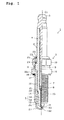
- Fig. 1 is a partial cross sectional view showing a configuration of a spark plug 1.
- a direction of an axis line C1 of the spark plug 1 is regarded as a top to bottom direction in Fig. 1 .
- a lower side of the drawing is regarded as a front end side of the spark plug 1 and an upper side of the drawing is regarded as a rear end side of the spark plug 1.
- a spark plug 1 is comprised of a cylindrical insulator serving as a insulating material, a cylindrical metal shell 3 accommodating the insulator 2 therein, and the like.
- the insulator 2 has an axial bore 4 therein which extends along the axis line C1.
- a center electrode 5 is inserted and fixed to a front end side of the axial bore 4, and a terminal electrode 6 is inserted and fixed to a rear end side of the axial bore 4.
- a resistor 7 is disposed between the center electrode 5 and the terminal electrode 6 in the axial bore 4, and the both ends of the resistor 7 are electrically connected to the center electrode 5 and the terminal electrode 6, respectively, through the conductive glass seal layers 8 and 9.
- the center electrode 5 is fixed so as to project from a front end of the insulator 2, and the terminal electrode 6 is fixed so as to project from a rear end of the insulator 2. Further, a noble metal tip 31 is joined to a front end of the center electrode 5 by welding (this will be described later) .
- the insulator 2 is formed by firing alumina or the like as is commonly known.
- the insulator 2 is comprised of a flange-shaped large diameter portion 11 radially projecting towards the outside and formed generally at a central area in the axis line C1, an intermediate body portion 12 formed at the front end side with respect to the large diameter portion 11 and having a smaller diameter than that of the large diameter portion 11, an elongated leg portion 13 formed at the front end side with respect to the intermediate body portion 12, having a smaller diameter than that of the intermediate body portion 12 and exposed to an combustion chamber of an internal combustion engine.
- the front end side of the insulator 2, which includes the large diameter portion 11, the intermediate body portion 12 and the elongated leg portion 13, is accommodated in the cylindrical metal shell 3.
- a step portion 14 is formed between the elongated leg portion 13 and the intermediate body portion 12 so that the insulator 2 is locked by the metal shell 3 at the step portion 14.
- the metal shell 3 is made of a metal, such as low-carbon steel, and assumes a cylindrical form.
- a male screw portion 15 for mounting the spark plug 1 on an engine cylinder head 41 (referring to Fig. 2 ) is formed on an outer circumference face of the metal shell 3.
- a flange portion 16 projecting towards the outer circumference is formed on the rear end side with respect to the male screw portion 15.
- a flat surface of the flange portion 16 located on the front end side serves as a gasket receiving portion 16a.
- a the thread neck 17 on which no thread ridges are formed has a smaller outer diameter than that of the male screw portion 15 and is formed between the rear end of the male screw portion 15 and the gasket receiving portion 16a.
- a ring-shaped gasket 18 is provided around the thread neck 17 (this will be described later). Furthermore, a tool engagement portion 19 having a hexagonal shape in a cross section is provided on the rear end side with respect to the metal shell 3 for engaging with a tool, such as a wrench, when mounting the metal shell 3 on the cylinder head 41. Also, a caulking portion 20 for holding the insulator 2 is provided in the rear end portion of the metal shell 3.
- a step portion 21 for locking the insulator 2 is formed in an inner circumference face of the metal shell 3.
- the insulator 2 is inserted towards the front end side from the rear end side of the metal shell 3 so that the step portion 14 is locked by the step portion 21 of the metal shell 3.
- an opening portion of the metal shell 3 at the rear end side is radially caulked in an inward direction, i.e., forming the caulking portion 20 to thereby fix the insulator 2 in the metal shell 3.
- an annular plate packing 22 is provided between the step portion 14 of the insulator 2 and the step portion 21 of the metal shell 3.
- annular ring members 23 and 24 are provided between the metal shell 3 and the insulator 2, and talc powder 25 is filled between the ring members 23 and 24. That is, the metal shell 3 holds the insulator 2 through the plate packing 22, the ring members 23, 24 and the talc 25.
- a generally L-shaped ground electrode 27 is joined to a front end face 26 of the metal shell 3. That is, a base end of the ground electrode 27 is welded to the front end face 26 of the metal shell 3, and a front end side of the ground electrode 27 is bent so that a side face of the ground electrode 27 faces the front end portion (the noble metal tip 31) of the center electrode 5.
- a noble metal tip 32 is provided so as to face the noble metal tip 31 to thereby form a spark-discharge gap 33 therebetween.
- the center electrode 5 is comprised of an inner layer 5A made of copper or a copper alloy and an outer layer 5B made of a nickel alloy. Further, the ground electrode 27 is made of nickel alloy or the like.
- the rod-like (columnar shape) center electrode 5 is tapered at front end side, and a front end face thereof is formed to be flat.
- the above-mentioned columnar noble metal tip 31 is joined to the front end face of the center electrode 5 by laser welding, electron beam welding or resistance welding along a joint face outer edge portion.
- the noble metal tip 32 facing the noble metal tip 31 is disposed on a predetermined location of the ground electrode 27, and the joint face outer edge portion is welded to thereby join the noble metal tip 32 to the ground electrode 27. It is noted that either the noble metal tip 31 or the noble metal tip 32 facing the noble metal tip 31 may be omitted. In this case, the spark-discharge gap 33 is formed between the noble metal tip 31 and a main body of the ground electrode 27, or between the noble metal tip 32 and a main body of the center electrode 5.
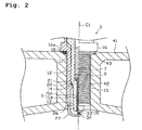
- the spark plug 1 is mounted on the cylinder head 41 of an engine by screwing the male screw portion 15 into a screw hole 42 of the cylinder head 41.
- the gasket 18 is compressed and crushed between the gasket receiving portion 16a and an opening circumference edge portion 43 of the screw hole 42 to thereby provide a seal between the screw hole 42 and the gasket receiving portion 16a.
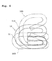
- the gasket 18 compressed and crushed after being mounted is shown with a two-dot chain line in Fig. 6 (refer to 18B in Fig. 6 ).
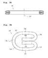
- the gasket 18 provided around the thread neck 17 assumes an annular shape and has an axial center C2 which serves as a center of the gasket 18.
- the gasket 18 is comprised of an inner tube portion 51, an upper large diameter portion 52, a lower large diameter portion 53, an upper plate-like portion 54, a lower plate-like portion 55, an upper bending portion 56, a lower bending portion 57, an upper intervening plate-like portion 58 and a lower intervening plate-like portion 59.
- the inner tube portion 51 constitutes an inner circumference face of the gasket 18 and extends in an axial direction (a direction where the axial center C2 extends).
- the upper large diameter portion 52 extends from the upper end in the axial direction of the inner tube portion 51 so that an inner diameter of the gasket gradually increases.
- the lower large diameter portion 53 extends from the lower end in the axial direction of the inner tube portion 51 so that an inner diameter of the gasket gradually increases.
- the upper plate-like portion 54 extends radially (i.e., perpendicular to the axial direction) from the upper large diameter portion 52
- the lower plate-like portion 55 extends radially (i.e., perpendicular to the axial direction) from the lower large diameter portion 53.
- the upper intervening plate-like portion 58 is integrally formed with the upper plate-like portion 54 through the upper bending portion 56 in a continuous manner and assumes a generally "U"-shape in the cross section.
- the lower intervening plate-like portion 59 is integrally formed with the lower plate-like portion 55 through the lower bending portion 57 in a continuous manner and assumes a generally "U"-shape in the cross section.
- the upper intervening plate-like portion 58 and the lower intervening plate-like portion 59 intervene between the upper plate-like portion 54 and the lower plate-like portion 55, and each plate-like portion 54, 55, 58, 59 is staked each other (for convenience' sake, each portion 51-59 is depicted with dotted-lines in Fig. 3B ).
- the minimum inner diameter of the inner tube portion 51 is larger than the outer diameter of the thread neck 17, as well as smaller than the outer diameter of the thread ridge of the male screw portion 15. Thereby, the gasket 18 is prevented from falling out from the thread neck 17.
- the inner tube portion 51 is not necessarily assumes a "linear shape in the cross section parallel to the axial direction", but may assume an circular arc shape in the cross section bulging towards the inner circumference side to some extent, as shown in the drawing, as long as it constitutes the inner circumference face of the gasket 18.
- the upper large diameter portion 52 and the lower large diameter portion 53 in this embodiment may have a radius of curvature varying according to each region thereof, as long as the inner diameter of the gasket gradually increases from the upper and lower ends of the inner tube portion 51 in the axial direction.
- the gasket assuming a meander shape in the cross section where the center of radius of curvature switches from inside to outside of the gasket.
- the upper plate-like portion 54 and the lower plate-like portion 55, or the upper intervening plate-like portion 58 and the lower intervening plate-like portion 59, all of which constitutes a plate-like portion assume a generally plate-like shape.
- it is not necessarily limited to strictly a plate-like (planar) shape. That is, as long as it can be recognized as "a shape extends in a radial direction perpendicular to the axial direction", some cumber, a curved shape like a loose arc is allowable.
- the upper plate-like portion 54 is positioned at the uppermost surface among all portions of the gasket 18 and the lower plate-like portion 55 is positioned at the lowermost surface among all portions of the gasket 18. Therefore, a portion bent further upwards over the upper plate-like portion 54 and a portion bent further downwards over the lower plate-like portion 55 are excluded in this embodiment.
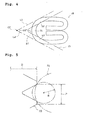
- the inner tube portion 51 does not assume a linear shape in the cross section, but assume a circular arc shape in the cross section bulging towards the inner circumference side.
- a radius of curvature R of the circular arc bulging towards the inner circumference side is set to be 0.44P or more (P referred to as a pitch between the threads of the male screw portion 15) in order to eradicate the concern.
- M10 9.794mm
- the gasket 18 in this embodiment has a configuration in which the minimum inner diameter of the inner tube portion 51 is larger than the outer diameter of the thread neck 17 and smaller than the outer diameter of the thread ridge of the male screw portion 15.
- the gasket before being provided around the thread neck 17 hereafter referred to as a "gasket before processing 18A"
- the minimum inner diameter of the inner tube portion 51A needs to be larger than the outer diameter of the thread ridge of the male screw portion 15.
- the gasket before processing 18A includes an inner tube portion 51A formed in an approximately linear shape and having a predetermined height. Similar to the gasket 18 after being mounted, the gasket before processing 18A is also comprised of an upper large diameter portion 52A, a lower large diameter portion 53A, an upper plate-like portion 54A, a lower plate-like portion 55A, an upper bending portion 56A, a lower bending portion 57A, an upper intervening plate-like portion 58A and a lower intervening plate-like portion 59A.
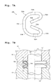
- a processing device 61 as shown in Fig. 7B is used. That is, the processing device 61 includes an upper press die 62, a lower press die 63 and a support rod 64. Each of these has rigidity higher than the material constituting the gasket 18 and is made of a metal material being unlikely to deform.
- the upper press die 62 and the lower press die 63 include an annular concave portion 65, 66, respectively, and insertion holes 67, 68 in which the cylindrical support rod 64 can be accommodated therein.
- a "gasket precursor before processing" generally having each portion 51A-59A of the gasket before processing 18A is prepared beforehand by a bending process or the like. Thereafter, the gasket precursor before processing is fitted around the support rod 64 and subjected to a press process by clamping it between the upper press die 62 and the lower press die 63. Then, the gasket precursor before processing is accommodated in the concave portion 65 and 66 to thereby being pressed from the top and bottom direction. At this time, a portion serving as the inner tube portion 51A receives a stress towards the inner circumference side. However, since the inner tube portion is in contact with an outer circumference face of the support rod 64, further deformation towards the inner circumference side is controlled.
- the inner tube portion 51A of the gasket before processing 18A which is obtained after the press process, assumes a linear shape extending in the axial center C2 direction (of course, the inner diameter of the inner tube portion 51A of the gasket before processing 18A is larger than the outer diameter of the thread ridge of the male screw portion 15).
- the processing device 61 shown in Fig. 7B is a part of the manufacturing devices of the gasket 18.
- the gasket 18 is manufactured using a multistage press machine which is formed by a plurality of processing devices that is similar to the processing device 61 is assembled in a multistage structure.
- the gasket before processing 18A goes through the male screw portion 15 and provided around the thread neck 17, it is again subjected to a press process that a flat face of a press jig (not illustrated) presses the gasket before processing 18A towards the gasket receiving portion 16a from the front end side of the spark plug 1 to thereby form the gasket 18. That is, the spark plug 1 serving as an "automotive component" is produced.
- the gasket 18 provided on the spark plug 1 assumes an identical cross sectional shape in an entire circumference thereof (i.e., there is no plurality of nail portions as mentioned in the description of the prior art).
- the gasket 18 of this embodiment includes the inner tube portion 51 extending in the axial center C2 direction and constituting the inner circumference face of the gasket 18.
- the gasket 18 is provided around the thread neck 17, it is possible to prevent the gasket 18 from falling out from the thread neck 17, as well as effectively preventing the male screw portion 15 from biting into the gasket.
- the two tangent lines L1 and L2 contacting the upper large diameter portion 52 and the lower large diameter portion 53, respectively, are drawn so that the intersection angle defined by the tangent lines L1,L2 is 60 degrees.
- the axial center C2 of the gasket 18 and the tangent lines L1, L2, and the axis line C1 of the spark plug 1 and the outer line of the male screw portion 15 are projected on the same virtual plane to thereby align the axial center C2 and the axis line C1.
- the intersection CP of the tangent lines L1, L2 is located on the inner circumference side with respect to the thread core BT of the male screw portion 15.
- the inner tube portion 51 does not assume the linear shape, but assume the circular arc shape in the cross section bulging towards the inner circumference side. Since the radius of curvature R of the circular arc is set to be 0.44P or more, the inner tube portion 51 does not practically enter into between the thread ridges. As a result, it is possible to securely prevent a failure due to the male screw portion 15 biting into the gasket 18.
- the gasket before processing 18A having the generally linear inner tube portion 51A is prepared in advance.
- the inner tube portion 51 is unlikely to point towards the inner side. That is, although the inner tube portion 51 of the gasket 18 assumes the circular arc shape in the cross section bulging towards the inner circumference side after the press process, the radius of curvature R of the circular arc is made large by forming the inner tube portion 51A of the gasket before processing 18A into the generally linear shape.
- the inner tube portion 51 of the gasket 18 assumes the circular arc shape in the cross section bulging towards the inner circumference side.
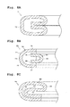
- an inner tube portion 72 of a gasket 71 may assume a linear shape in the cross section parallel to the axial direction.
- the gasket 18 is comprised of the inner tube portion 51, the upper large diameter portion 52, the lower large diameter portion 53, the upper plate-like portion 54, the lower plate-like portion 55, the upper bending portion 56, the lower bending portion 57, the upper intervening plate-like portion 58 and the lower intervening plate-like portion 59.
- These plate-like portions 51-59 are integrally formed in the continuous manner. However, they are not necessarily formed in this way. As shown in Fig.
- a gasket 85 may be comprised of: an inner ring portion 78 constituted by an inner tube portion 73, an upper large diameter portion 74, a lower large diameter portion 75, an upper plate-like portion 76 and a lower plate-like portion 77; and an outer ring portion 84 constituted by an upper intervening plate-like portion 81, a lower intervening plate-like portion 82 and a bend portion 83 connecting between the upper intervening plate-like portion 81 and the lower intervening plate-like portion 82.
- the entire circumference of inner ring portion 78 is formed in a continuous manner (joined without break) in order to secure a predetermined airtightness.
- the outer ring portion 84 may have a cut line therein (a beginning end and a terminal end).
- the upper intervening plate-like portion 58 of the gasket 18 is integrally formed with the upper plate-like portion 54 in the continuous manner through the upper bending portion 56.
- the lower intervening plate-like portion 59 is integrally formed with the lower plate-like portion 55 in the continuous manner through the lower bending portion 57.
- an upper intervening plate-like portion 87 of a gasket 86 may be integrally formed with an upper plate-like portion 88 in the continuous manner through an upper bending portion 89.
- a lower intervening plate-like portion 90 may be integrally formed with the upper intervening plate-like portion 87 in the continuous manner through a bend portion 91.
- the lower intervening plate-like portion is integrally formed with the lower plate-like portion in the continuous manner through the lower bending portion.
- the upper intervening plate-like portion may be integrally formed with the lower intervening plate-like portion in the continuous manner through the bend portion (not illustrated).
- the upper large diameter portion 52 and the lower large diameter portion 53 assumes the circular arc shape in the cross section in the above-mentioned embodiment, they may assume a generally linear shape in the cross section as long as they extends from the upper and lower ends of the inner tube portion 51 in the axial direction so that the inner diameter of the gasket gradually increases.
- the above-mentioned conditions may be fulfilled in such a manner that the tangent lines L1,L2 contacting an upper portion and a lower portion of the inner tube portion, respectively, (instead of the upper large diameter portion and the lower large diameter portion) are drawn depending on the shape of a gasket.
- the upper intervening plate-like portion 58 and the lower intervening plate-like portion 59 serving as the intervening plate-like portion are provided.
- the upper intervening plate-like portion or the lower intervening plate-like portion may be provided.
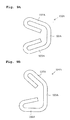
- an angle defined by an inner tube portion 105A and a lower plate-like portion 106A of a gasket before processing 104A may be a generally right angle
- an angle defined by the inner tube portion 105A and an upper plate-like portion 107A may be an obtuse angle
- a material of the gasket 18 is not limited, copper, zinc, aluminium, iron or an alloy containing one of the above material (e.g., stainless steel or the like) may be employed.
Landscapes
- Chemical & Material Sciences (AREA)
- Engineering & Computer Science (AREA)
- Combustion & Propulsion (AREA)
- Spark Plugs (AREA)
- Ignition Installations For Internal Combustion Engines (AREA)
- Gasket Seals (AREA)
Abstract

Description
- The present invention relates to a gasket provided around a thread neck of an automotive component, such as a spark plug for combustion engines and a sensor, and to an automotive component where the gasket is installed.
- A conventional spark plug used for igniting a combustion engine, such as a gasoline engine for automobiles is comprised of a center electrode, an insulator accommodating the center electrode therein, a cylindrical metal shell accommodating the insulator therein and a ground electrode in which a base end thereof is joined to a front end portion of the metal shell. A male screw portion is formed around an outer circumference face of the metal shell, and an annular gasket receiving portion projecting outwardly is formed on a rear end side of the male screw portion. On the other hand, a screw hole having a female screw portion is formed in an engine cylinder head. The spark plug is mounted on the engine by screwing the male screw portion into the screw hole. Here, a portion called a the thread neck is provided between a rear end side of the male screw portion of the metal shell and the gasket receiving portion, and an annular gasket is provided around the thread neck. With screwing the male screw portion into the screw hole, the gasket is compressed and crushed between the gasket receiving portion and an opening circumference edge portion of the screw hole to thereby provide a seal between the screw hole and the gasket receive portion.
- As a common gasket, it has been known that a gasket formed such that a ring-shaped thin metal plate is radially bent with a special die into, for example, a generally "S" shape in a cross sectional view, which is so to speak a hollow shape. Such a gasket is subjected to a predetermined nail forming process after being fitted around the thread neck to thereby form a plurality of nail portions (e.g., three nails) projecting in an inner circumference direction. Thus, in the conventional gasket, the nail portion is formed after the gasket is fitted around the thread neck so as to prevent the gasket from falling out from the thread neck (e.g., refer to
Patent Document 1 or the like). [Patent documents 1] Japanese Laid-Open Utility Model Application No.Sho 59-39894 - In recent years, automation has been advanced in various industrial fields. Spark plugs are also automatically mounted on engines using a robot. More particularly, a large number of spark plugs where gaskets are provided is tidily allocated in support holes of a pallet, and a robot picks up a spark plug from the pallet and conveys it to an engine. Then, the robot tightly screws a male screw portion of the spark plug into a screw hole of an engine cylinder head. In addition, when the spark plug is automatically mounted on the engine cylinder head, the spark plug is supported in a state where the gasket is in contact with a circumference of the support hole of the pallet and extends in a vertical direction.
- However, the conventional spark plug tends to have a problem that a nail portion of the gasket is likely to enter into between adjacent thread ridges of the male screw portion, and also the male screw portion bites into the nail portion. When this problem occurs, the gasket inclines with respect to an axial center of the spark plug when mounted. Therefore, in this case, the spark plug having the inclined gasket with respect to the circumference of the support hole of the pallet is supported at the time of the automatic mounting operation. That is, the spark plug is supported in an inclined state. Therefore, there is a possibility that the robot may incorrectly operate a removal control or may judge that a supporting position of the spark plug is not in a scheduled location. As a result, the mounting operation of the spark plug on the engine may be hampered.
- In addition, the problem that the male screw portion bites into the gasket as mentioned above does not only occur to the spark plug where the gasket is provided, but also occurs to automotive components, such as sensors, where various kinds of gaskets are provided.
- The present invention has been accomplished in light of the above-mentioned problems, and an object of the present invention is to provide a gasket provided around a thread neck of an automotive component. The invention prevents the gasket from falling out, as well as effectively preventing a male screw portion from biting into the gasket.
- Each aspect suitable for solving the above-mentioned problems will be described. In addition, any specific effect or the like of each aspect will be noted if necessary.
-
Aspect 1. In an automotive component, comprising, from a front end to a rear end in an axial direction: - a male screw portion;
- a thread neck having a smaller outer diameter than that of a thread ridge of the male screw portion; and
- a gasket receiving portion having a flat face facing the front end direction and located at a rear end side of the thread neck,
- an annular gasket provided around the thread neck which is formed between the male screw portion and the gasket receiving portion, having an axial center which serves as a center of the gasket, and being formed such that a plurality of plate-like portions is stacked in the axial direction,
- Although the inner tube portion in
aspect 1 is described as "extending in the axial direction", it is not necessarily limited to strictly a "linear shape parallel to the axial direction in the cross section", as long as the inner tube portion "constitutes the inner circumference face of the gasket". Thus, the inner tube portion may assume a circular arc shape in the cross section, which slightly bulges into the inner circumference side. - Further, the upper large diameter portion or the lower large diameter portion in
aspect 1 may have a radius of curvature varying according to each region thereof, as long as the inner diameter of the gasket gradually increases from the upper end and lower end of the inner tube portion in the axial direction. However, it is excluded that the gasket assuming a meander shape in the cross section where the center of the radius of curvature switches from the inside to the outside of the gasket. The upper large diameter portion and the lower large diameter portion may assume a generally linear shape in the cross section. - Furthermore, the upper plate-like portion and the lower plate-like portion and the intervening plate-like portion, all of which constitute the plate-like portion, assume a generally plate-like shape. However, it is not necessarily limited to strictly a plate-like (planar) shape. That is, as long as the upper plate-like portion and the lower plate-like portion or the intervening plate-like portion are recognized as "a shape extends in a radial direction perpendicular to the axial direction", a curved shape like drawing a gradual arc is acceptable.
- Moreover, the "intervening plate-like portion", which intervenes between the upper plate-like portion and the lower plate-like portion, constitutes a piece of the "plate-like portions". A configuration of the "intervening plate-like portion" may be a single piece or plural pieces.
- In
aspect 1, "the upper plate-like portion may be positioned at the uppermost surface among all portions of the gasket and the lower plate-like portion 55 may be positioned at the lowermost surface among all portions of the gasket". When the configuration of the gasket is limited in this way, a portion bent further upwards over the upper plate-like portion and a portion bent further downwards over the lower plate-like portion are excluded. - According to
aspect 1, when the male screw portion is screwed into a fitting portion, such as an engine screw hole, the gasket is compressed and crushed between the gasket receiving portion and the opening circumference edge portion of the screw hole so as to provide a seal between the screw hole and the gasket receiving portion. At this time, the upper plate-like portion, the lower plate-like portion and the intervening plate-like portion, all of which constitute the plate-like portions, are stacked, and the gasket is deformed to thereby reduce the distance between the plate-like portions. - In
aspect 1, the minimum inner diameter of the inner tube portion is larger than the outer diameter of the thread neck and smaller than the outer diameter of the thread ridge of the male screw portion. Thus, it is possible to prevent the gasket from falling out from the thread neck. Since the gasket before being provided around the thread neck is necessarily fitted around the thread neck, the minimum inner diameter of the inner tube portion needs to be larger than the outer diameter of the thread ridge of the male screw portion. As will be described later, the gasket before being provided around the thread neck (hereafter referred to as a "gasket before processing") is preferably formed so that a portion serving as the inner tube portion assumes a generally linear shape, and has a predetermined height. The gasket according toaspect 1 is formed by compressing the gasket before processing in the height direction after being installed. - The gasket includes the inner tube portion extending in the axial center direction, and the inner tube portion constitutes the inner circumference face of the gasket. Thus, unlike a conventional art where a nail portion points in an inward direction tends to enter into between the thread ridges of the male screw portion, the male screw portion is unlikely to bite into the inner tube portion. As a result, when the gasket is provided around the thread neck, it is possible to prevent the gasket from falling out from the thread neck, as well as effectively preventing the male screw portion from biting into the gasket.
- Further, the above-mentioned effect can be more definitive when an
aspect 2 described next is carried out. -
Aspect 2. In addition toaspect 1, a gasket according to anaspect 2, wherein, in the cross sectional view passing through the axial center of the gasket, two tangent lines contacting the upper large diameter portion and the lower large diameter portion, respectively, are drawn so that an intersection angle defined by the tangent lines is 60 degrees, wherein the axial center of the gasket and the tangent lines, and the axis line of an automotive component and an outer line of the male screw portion are projected on the same virtual plane to thereby align the axial center and the axis line, wherein the intersection of the tangent lines is located on an inner circumference side with respect to a thread core of the male screw portion. -
Aspect 2 further limits the shape of the inner tube portion or the upper large diameter portion and the lower large diameter portion of the gasket according toaspect 1. That is, in the cross sectional view passing through the axial center of the gasket, two tangent lines contacting the upper large diameter portion and the lower large diameter portion, respectively, are drawn so that the intersection angle defined by the tangent lines is 60 degrees. Further, the axial center of the gasket and the tangent lines, and the axis line of the automotive component and the outer line of the male screw portion are projected on the same virtual plane to thereby align the axis center and the axis line. Here, "...projected... to thereby align ..." means a state that the tangent lines of the gasket and the male screw portion are overlapped on the virtual plane. That is, since it is impossible to visually recognize that the virtual tangent lines to slide, it is specified as a "projection". When the above projection is conducted, the intersection of two tangent lines is located on the inner circumference side with respect to the thread core of the male screw portion. In this way, the inner tube portion does not enter into between the thread ridges whereby it is possible to reliably prevent a failure caused by the male screw portion biting into the gasket. -
Aspect 3. In addition toaspect aspect 3, wherein all the plate-like portions are integrally formed in a continuous manner. - Basically, all the configurations mentioned above are necessarily provided. The intervening plate-like portion may not be necessarily integrally formed with the upper plate-like portion or the lower plate-like portion in a continuous manner, as long as it intervenes between the upper plate-like portion and the lower plate-like portion. The gasket may be formed by a plurality of separate parts. On the other hand, in
aspect 3, all the plate-like portions are integrally formed in the continuous manner. That is, the intervening plate-like portion is integrally formed with the upper plate-like portion or the lower plate-like portion in the continuous manner. Therefore, any defect caused by a gasket that is formed by a plurality of separate parts, such as complication at the time of manufacturing of a gasket (e.g., assembly of plural parts) or a sealing failure due to a positional misalignment of each part at the time of clamping, can be prevented. -
Aspect 4. In addition to any one of aspect from 1 to 3, the gasket according to anaspect 4, wherein the intervening plate-like portion is comprised of an upper intervening plate-like portion and a lower intervening plate-like portion, wherein the upper intervening plate-like portion is integrally formed with the upper plate-like portion in a continuous manner through an upper bending portion, and wherein the lower intervening plate-like portion is integrally formed with the lower plate-like portion in a continuous manner through a lower bending portion. - According to
aspect 4, the upper plate-like portion, the lower plate-like portion, the upper intervening plate-like portion and the lower intervening plate-like portion, all of which constitute plate-like portions, are stacked, and the gasket is deformed to thereby reduce the distance between the plate-like portions. -
Aspect 5. In addition to any one ofaspects 1 to 4, a gasket according to anaspect 5, wherein the inner tube portion assumes either a linear shape in the cross section parallel to the axial direction or a circular arc shape in the cross section with a radius of curvature R of 0.44P or more (P referred to as a thread pitch) bulging towards an inner circumference side (unit of R and P is millimeter) . - According to
aspect 5, the inner tube portion assumes either the linear shape in the cross section parallel to the axial direction or the circular arc shape in the cross section with the radius of curvature R of 0.44P or more bulging towards the inner circumference side. Therefore, the inner tube portion does not enter into between the thread ridges whereby it is possible to reliably prevent a failure caused by the male screw portion biting into the gasket. - The reason for selecting a "radius of curvature R of 0.44P or more" will be explained. As a male screw portion used for a spark plug or the like, a typical thread diameter is M14, M12 or M10. According to JIS B8031, as for M14, a thread pitch is 1.25mm and a thread outer diameter is 13.725mm. As for M12, a thread pitch is 1. 25mm and a thread outer diameter is 11.725mm. As for M10, a thread pitch is 1.00mm and a thread outer diameter is 9.794mm (the above-mentioned values are the minimum values specified in JIS specification). Furthermore, when considering an angle of the thread core, which is set to be 60 degrees, the minimum inner diameter of the gasket can be also calculated using the above-mentioned value. After calculating the minimum inner diameter of the gasket, the minimum radius of curvature (R1) where the inner tube portion does not enter into between thread ridges can be calculated. For M14: R1=0.545mm; M12: R1=0.545mm; M10: R1=0.444mm. Then, when each minimum radius of curvature (R1) is divided by the respective thread pitch, M14 and M12 are 0.436, and M10 is 0.444. As a result, even though the inner tube portion assumes the circular arc shape in the cross section bulging towards the inner circumference side, it does not practically enter into between the thread ridges as long as the radius of curvature R is 0.44P or more.
- Moreover, as in an
aspect 6, the technical concept of each invention can also be embodied in an automotive component. -
Aspect 6. An automotive component, comprising a gasket according to any one ofaspects 1 to 5. - In addition, as a typical automotive component, it is possible to cite a spark plug, a sensor or the like. [Best Mode for Carrying Out the Invention]
- Hereafter, an embodiment of the present invention will be described with reference to the drawings.
Fig. 1 is a partial cross sectional view showing a configuration of aspark plug 1. A direction of an axis line C1 of thespark plug 1 is regarded as a top to bottom direction inFig. 1 . A lower side of the drawing is regarded as a front end side of thespark plug 1 and an upper side of the drawing is regarded as a rear end side of thespark plug 1. - A
spark plug 1 is comprised of a cylindrical insulator serving as a insulating material, acylindrical metal shell 3 accommodating theinsulator 2 therein, and the like. - The
insulator 2 has anaxial bore 4 therein which extends along the axis line C1. Acenter electrode 5 is inserted and fixed to a front end side of theaxial bore 4, and aterminal electrode 6 is inserted and fixed to a rear end side of theaxial bore 4. Aresistor 7 is disposed between thecenter electrode 5 and theterminal electrode 6 in theaxial bore 4, and the both ends of theresistor 7 are electrically connected to thecenter electrode 5 and theterminal electrode 6, respectively, through the conductive glass seal layers 8 and 9. - The
center electrode 5 is fixed so as to project from a front end of theinsulator 2, and theterminal electrode 6 is fixed so as to project from a rear end of theinsulator 2. Further, anoble metal tip 31 is joined to a front end of thecenter electrode 5 by welding (this will be described later) . - On the other hand, the
insulator 2 is formed by firing alumina or the like as is commonly known. Theinsulator 2 is comprised of a flange-shapedlarge diameter portion 11 radially projecting towards the outside and formed generally at a central area in the axis line C1, anintermediate body portion 12 formed at the front end side with respect to thelarge diameter portion 11 and having a smaller diameter than that of thelarge diameter portion 11, anelongated leg portion 13 formed at the front end side with respect to theintermediate body portion 12, having a smaller diameter than that of theintermediate body portion 12 and exposed to an combustion chamber of an internal combustion engine. The front end side of theinsulator 2, which includes thelarge diameter portion 11, theintermediate body portion 12 and theelongated leg portion 13, is accommodated in thecylindrical metal shell 3. Astep portion 14 is formed between theelongated leg portion 13 and theintermediate body portion 12 so that theinsulator 2 is locked by themetal shell 3 at thestep portion 14. - The
metal shell 3 is made of a metal, such as low-carbon steel, and assumes a cylindrical form. Amale screw portion 15 for mounting thespark plug 1 on an engine cylinder head 41 (referring toFig. 2 ) is formed on an outer circumference face of themetal shell 3. Aflange portion 16 projecting towards the outer circumference is formed on the rear end side with respect to themale screw portion 15. A flat surface of theflange portion 16 located on the front end side serves as agasket receiving portion 16a. A thethread neck 17 on which no thread ridges are formed has a smaller outer diameter than that of themale screw portion 15 and is formed between the rear end of themale screw portion 15 and thegasket receiving portion 16a. A ring-shapedgasket 18 is provided around the thread neck 17 (this will be described later). Furthermore, atool engagement portion 19 having a hexagonal shape in a cross section is provided on the rear end side with respect to themetal shell 3 for engaging with a tool, such as a wrench, when mounting themetal shell 3 on thecylinder head 41. Also, acaulking portion 20 for holding theinsulator 2 is provided in the rear end portion of themetal shell 3. - Moreover, a
step portion 21 for locking theinsulator 2 is formed in an inner circumference face of themetal shell 3. Theinsulator 2 is inserted towards the front end side from the rear end side of themetal shell 3 so that thestep portion 14 is locked by thestep portion 21 of themetal shell 3. Then, an opening portion of themetal shell 3 at the rear end side is radially caulked in an inward direction, i.e., forming thecaulking portion 20 to thereby fix theinsulator 2 in themetal shell 3. It is noted that an annular plate packing 22 is provided between thestep portion 14 of theinsulator 2 and thestep portion 21 of themetal shell 3. Thus, airtightness in a combustion chamber is kept, and a fuel air introduced to a gap between theelongated leg portion 13 of theinsulator 2, which is exposed to the combustion chamber, and the inner circumference face of themetal shell 3 is prevented from leaking out. - Furthermore, in order to achieve a perfect sealing by caulking, on the rear end side of the
metal shell 3,annular ring members metal shell 3 and theinsulator 2, andtalc powder 25 is filled between thering members metal shell 3 holds theinsulator 2 through the plate packing 22, thering members talc 25. - Moreover, a generally L-shaped
ground electrode 27 is joined to a front end face 26 of themetal shell 3. That is, a base end of theground electrode 27 is welded to the front end face 26 of themetal shell 3, and a front end side of theground electrode 27 is bent so that a side face of theground electrode 27 faces the front end portion (the noble metal tip 31) of thecenter electrode 5. In theground electrode 27, anoble metal tip 32 is provided so as to face thenoble metal tip 31 to thereby form a spark-discharge gap 33 therebetween. - The
center electrode 5 is comprised of aninner layer 5A made of copper or a copper alloy and anouter layer 5B made of a nickel alloy. Further, theground electrode 27 is made of nickel alloy or the like. - The rod-like (columnar shape)
center electrode 5 is tapered at front end side, and a front end face thereof is formed to be flat. The above-mentioned columnarnoble metal tip 31 is joined to the front end face of thecenter electrode 5 by laser welding, electron beam welding or resistance welding along a joint face outer edge portion. On the other hand, thenoble metal tip 32 facing thenoble metal tip 31 is disposed on a predetermined location of theground electrode 27, and the joint face outer edge portion is welded to thereby join thenoble metal tip 32 to theground electrode 27. It is noted that either thenoble metal tip 31 or thenoble metal tip 32 facing thenoble metal tip 31 may be omitted. In this case, the spark-discharge gap 33 is formed between thenoble metal tip 31 and a main body of theground electrode 27, or between thenoble metal tip 32 and a main body of thecenter electrode 5. - Hereafter, the
gasket 18 that is a characteristic feature of this embodiment will be described in detail. As shown inFig. 2 , thespark plug 1 is mounted on thecylinder head 41 of an engine by screwing themale screw portion 15 into ascrew hole 42 of thecylinder head 41. Thegasket 18 is compressed and crushed between thegasket receiving portion 16a and an openingcircumference edge portion 43 of thescrew hole 42 to thereby provide a seal between thescrew hole 42 and thegasket receiving portion 16a. In addition, thegasket 18 compressed and crushed after being mounted is shown with a two-dot chain line inFig. 6 (refer to 18B inFig. 6 ). - Before screwing the
spark plug 1 into thescrew hole 42 of thecylinder head 41, as shown inFig. 3A , thegasket 18 provided around thethread neck 17 assumes an annular shape and has an axial center C2 which serves as a center of thegasket 18. As shown inFig. 3B , thegasket 18 is comprised of aninner tube portion 51, an upperlarge diameter portion 52, a lowerlarge diameter portion 53, an upper plate-like portion 54, a lower plate-like portion 55, anupper bending portion 56, alower bending portion 57, an upper intervening plate-like portion 58 and a lower intervening plate-like portion 59. - More particularly, the
inner tube portion 51 constitutes an inner circumference face of thegasket 18 and extends in an axial direction (a direction where the axial center C2 extends). The upperlarge diameter portion 52 extends from the upper end in the axial direction of theinner tube portion 51 so that an inner diameter of the gasket gradually increases. The lowerlarge diameter portion 53 extends from the lower end in the axial direction of theinner tube portion 51 so that an inner diameter of the gasket gradually increases. Further, the upper plate-like portion 54 extends radially (i.e., perpendicular to the axial direction) from the upperlarge diameter portion 52, and the lower plate-like portion 55 extends radially (i.e., perpendicular to the axial direction) from the lowerlarge diameter portion 53. - Furthermore, the upper intervening plate-
like portion 58 is integrally formed with the upper plate-like portion 54 through theupper bending portion 56 in a continuous manner and assumes a generally "U"-shape in the cross section. The lower intervening plate-like portion 59 is integrally formed with the lower plate-like portion 55 through thelower bending portion 57 in a continuous manner and assumes a generally "U"-shape in the cross section. The upper intervening plate-like portion 58 and the lower intervening plate-like portion 59 intervene between the upper plate-like portion 54 and the lower plate-like portion 55, and each plate-like portion Fig. 3B ). - In a state where before the
spark plug 1 is mounted on theengine cylinder head 41, i.e., thespark plug 1 serves as an "automotive component" before being mounted, the minimum inner diameter of theinner tube portion 51 is larger than the outer diameter of thethread neck 17, as well as smaller than the outer diameter of the thread ridge of themale screw portion 15. Thereby, thegasket 18 is prevented from falling out from thethread neck 17. - The
inner tube portion 51 is not necessarily assumes a "linear shape in the cross section parallel to the axial direction", but may assume an circular arc shape in the cross section bulging towards the inner circumference side to some extent, as shown in the drawing, as long as it constitutes the inner circumference face of thegasket 18. - Further, the upper
large diameter portion 52 and the lowerlarge diameter portion 53 in this embodiment may have a radius of curvature varying according to each region thereof, as long as the inner diameter of the gasket gradually increases from the upper and lower ends of theinner tube portion 51 in the axial direction. However, it is excluded that the gasket assuming a meander shape in the cross section where the center of radius of curvature switches from inside to outside of the gasket. - Further, the upper plate-
like portion 54 and the lower plate-like portion 55, or the upper intervening plate-like portion 58 and the lower intervening plate-like portion 59, all of which constitutes a plate-like portion, assume a generally plate-like shape. However, it is not necessarily limited to strictly a plate-like (planar) shape. That is, as long as it can be recognized as "a shape extends in a radial direction perpendicular to the axial direction", some cumber, a curved shape like a loose arc is allowable. - In this embodiment, the upper plate-
like portion 54 is positioned at the uppermost surface among all portions of thegasket 18 and the lower plate-like portion 55 is positioned at the lowermost surface among all portions of thegasket 18. Therefore, a portion bent further upwards over the upper plate-like portion 54 and a portion bent further downwards over the lower plate-like portion 55 are excluded in this embodiment. - Referring to the
inner tube portion 51, in the cross sectional view passing through the axial center C2 as shown inFig. 4 , two tangent lines L1 and L2 contacting the upperlarge diameter portion 52 and the lowerlarge diameter portion 53, respectively, are drawn so that an intersection angle defined by the tangent lines L1,L2 is 60 degrees. The axial center C2 of thegasket 18 and the tangent lines L1, L2 and the axis line C1 of thespark plug 1 and the outer line of the male screw portion 15 (thread ridge, thread core) are projected on the same virtual plane to thereby align the axial center C2 and the axis line C1. On this projection view, an intersection CP of the tangent lines L1, L2 is located on an inner circumference side (left-hand side inFig. 4 ) with respect to a thread core BT of themale screw portion 15. - Furthermore, in this embodiment, the
inner tube portion 51 does not assume a linear shape in the cross section, but assume a circular arc shape in the cross section bulging towards the inner circumference side.
However, when the radius of curvature of the circular arc is too small, there is a concern that theinner tube portion 51 enters into between the thread ridges. As shown inFig. 5 , in this embodiment, a radius of curvature R of the circular arc bulging towards the inner circumference side is set to be 0.44P or more (P referred to as a pitch between the threads of the male screw portion 15) in order to eradicate the concern. A thread diameter of themale screw portion 15 of thespark plug 1 is typically selected from either M14 (outer diameter D of the thread ridge = 13.725mm), M12 (outer diameter D of the thread ridge = 11.725mm) or M10 (outer diameter D of the thread ridge = 9.794mm). When these thread diameters are adopted and the radius of curvature R is 0.44P or more, theinner tube portion 51 does not practically enter into between the thread ridges. - As mentioned above, the
gasket 18 in this embodiment has a configuration in which the minimum inner diameter of theinner tube portion 51 is larger than the outer diameter of thethread neck 17 and smaller than the outer diameter of the thread ridge of themale screw portion 15. However, the gasket before being provided around the thread neck 17 (hereafter referred to as a "gasket before processing 18A") is necessarily fitted around the thread neck. Thus, the minimum inner diameter of theinner tube portion 51A needs to be larger than the outer diameter of the thread ridge of themale screw portion 15. - The gasket before processing 18A will be described. As shown in
Fig. 6 with a continuous line and inFig. 7A with a two-dot chain line, the gasket before processing 18A includes aninner tube portion 51A formed in an approximately linear shape and having a predetermined height. Similar to thegasket 18 after being mounted, the gasket before processing 18A is also comprised of an upperlarge diameter portion 52A, a lowerlarge diameter portion 53A, an upper plate-like portion 54A, a lower plate-like portion 55A, anupper bending portion 56A, alower bending portion 57A, an upper intervening plate-like portion 58A and a lower intervening plate-like portion 59A. - Thus, in order to obtain the gasket before processing 18A which has the generally linear
inner tube portion 51A, for example, aprocessing device 61 as shown inFig. 7B is used. That is, theprocessing device 61 includes an upper press die 62, a lower press die 63 and asupport rod 64. Each of these has rigidity higher than the material constituting thegasket 18 and is made of a metal material being unlikely to deform. The upper press die 62 and the lower press die 63 include an annularconcave portion 65, 66, respectively, and insertion holes 67, 68 in which thecylindrical support rod 64 can be accommodated therein.
A "gasket precursor before processing" generally having eachportion 51A-59A of the gasket before processing 18A is prepared beforehand by a bending process or the like. Thereafter, the gasket precursor before processing is fitted around thesupport rod 64 and subjected to a press process by clamping it between the upper press die 62 and the lower press die 63. Then, the gasket precursor before processing is accommodated in theconcave portion 65 and 66 to thereby being pressed from the top and bottom direction. At this time, a portion serving as theinner tube portion 51A receives a stress towards the inner circumference side. However, since the inner tube portion is in contact with an outer circumference face of thesupport rod 64, further deformation towards the inner circumference side is controlled. For this reason, theinner tube portion 51A of the gasket before processing 18A, which is obtained after the press process, assumes a linear shape extending in the axial center C2 direction (of course, the inner diameter of theinner tube portion 51A of the gasket before processing 18A is larger than the outer diameter of the thread ridge of the male screw portion 15).
In addition, theprocessing device 61 shown inFig. 7B is a part of the manufacturing devices of thegasket 18. In reality, thegasket 18 is manufactured using a multistage press machine which is formed by a plurality of processing devices that is similar to theprocessing device 61 is assembled in a multistage structure. - When the gasket before processing 18A goes through the
male screw portion 15 and provided around thethread neck 17, it is again subjected to a press process that a flat face of a press jig (not illustrated) presses the gasket before processing 18A towards thegasket receiving portion 16a from the front end side of thespark plug 1 to thereby form thegasket 18. That is, thespark plug 1 serving as an "automotive component" is produced. As is apparent from the above-described manufacturing process, thegasket 18 provided on thespark plug 1 assumes an identical cross sectional shape in an entire circumference thereof (i.e., there is no plurality of nail portions as mentioned in the description of the prior art). - As is described in detail in the above, the
gasket 18 of this embodiment includes theinner tube portion 51 extending in the axial center C2 direction and constituting the inner circumference face of thegasket 18. Thus, unlike the conventional gasket where a nail portion thereof extending and pointing in an inward direction tends to enter into between the thread ridges of the male screw portion, it is possible to prevent themale screw portion 15 from biting into theinner tube portion 51 because theinner tube portion 51 has a predetermined height. As a result, when thegasket 18 is provided around thethread neck 17, it is possible to prevent thegasket 18 from falling out from thethread neck 17, as well as effectively preventing themale screw portion 15 from biting into the gasket. - In this embodiment, in the cross sectional view passing through the axial center C2, the two tangent lines L1 and L2 contacting the upper
large diameter portion 52 and the lowerlarge diameter portion 53, respectively, are drawn so that the intersection angle defined by the tangent lines L1,L2 is 60 degrees. The axial center C2 of thegasket 18 and the tangent lines L1, L2, and the axis line C1 of thespark plug 1 and the outer line of themale screw portion 15 are projected on the same virtual plane to thereby align the axial center C2 and the axis line C1.
On the projection view, the intersection CP of the tangent lines L1, L2 is located on the inner circumference side with respect to the thread core BT of themale screw portion 15. Further, theinner tube portion 51 does not assume the linear shape, but assume the circular arc shape in the cross section bulging towards the inner circumference side. Since the radius of curvature R of the circular arc is set to be 0.44P or more, theinner tube portion 51 does not practically enter into between the thread ridges. As a result, it is possible to securely prevent a failure due to themale screw portion 15 biting into thegasket 18. - Moreover, in order to obtain the
gasket 18 having the above describedinner tube portion 51, the gasket before processing 18A having the generally linearinner tube portion 51A is prepared in advance. Thus, when performing the press process after the gasket before processing 18A goes through themale screw portion 15, theinner tube portion 51 is unlikely to point towards the inner side. That is, although theinner tube portion 51 of thegasket 18 assumes the circular arc shape in the cross section bulging towards the inner circumference side after the press process, the radius of curvature R of the circular arc is made large by forming theinner tube portion 51A of the gasket before processing 18A into the generally linear shape. - The present invention is not limited to the above-described embodiment, but may be modified as follows.
- (a) In the above-mentioned embodiment, the
inner tube portion 51 of thegasket 18 assumes the circular arc shape in the cross section bulging towards the inner circumference side. However, as shown inFig. 8A , aninner tube portion 72 of agasket 71 may assume a linear shape in the cross section parallel to the axial direction. - (b) The
gasket 18 is comprised of theinner tube portion 51, the upperlarge diameter portion 52, the lowerlarge diameter portion 53, the upper plate-like portion 54, the lower plate-like portion 55, theupper bending portion 56, thelower bending portion 57, the upper intervening plate-like portion 58 and the lower intervening plate-like portion 59. These plate-like portions 51-59 are integrally formed in the continuous manner. However, they are not necessarily formed in this way. As shown inFig. 8B , for example, agasket 85 may be comprised of: aninner ring portion 78 constituted by aninner tube portion 73, an upperlarge diameter portion 74, a lowerlarge diameter portion 75, an upper plate-like portion 76 and a lower plate-like portion 77; and anouter ring portion 84 constituted by an upper intervening plate-like portion 81, a lower intervening plate-like portion 82 and abend portion 83 connecting between the upper intervening plate-like portion 81 and the lower intervening plate-like portion 82. In addition, in the above-mentioned configuration, the entire circumference ofinner ring portion 78 is formed in a continuous manner (joined without break) in order to secure a predetermined airtightness. On the other hand, theouter ring portion 84 may have a cut line therein (a beginning end and a terminal end). - (c) In the above-mentioned embodiment, the upper intervening plate-
like portion 58 of thegasket 18 is integrally formed with the upper plate-like portion 54 in the continuous manner through theupper bending portion 56. The lower intervening plate-like portion 59 is integrally formed with the lower plate-like portion 55 in the continuous manner through thelower bending portion 57. On the other hand, as shown inFig. 8C , for example, an upper intervening plate-like portion 87 of agasket 86 may be integrally formed with an upper plate-like portion 88 in the continuous manner through anupper bending portion 89. Further, a lower intervening plate-like portion 90 may be integrally formed with the upper intervening plate-like portion 87 in the continuous manner through abend portion 91. Reversely, the lower intervening plate-like portion is integrally formed with the lower plate-like portion in the continuous manner through the lower bending portion. Further, the upper intervening plate-like portion may be integrally formed with the lower intervening plate-like portion in the continuous manner through the bend portion (not illustrated). - (d) Although the upper
large diameter portion 52 and the lowerlarge diameter portion 53 assumes the circular arc shape in the cross section in the above-mentioned embodiment, they may assume a generally linear shape in the cross section as long as they extends from the upper and lower ends of theinner tube portion 51 in the axial direction so that the inner diameter of the gasket gradually increases. - (e) In the above-mentioned embodiment, in the cross sectional view passing through the axial center C2, two tangent lines L1 and L2 contacting the upper
large diameter portion 52 and the lowerlarge diameter portion 53, respectively, are drawn so that the intersection angle defined by the tangent lines L1,L2 is 60 degrees. While the axial center C2 is aligned with the axis line C1, the tangent lines L1,L2 are projected on the male screw portion 15 (thread ridge, thread core). On the projection view, the intersection CP of the tangent lines L1,L2 is located on the inner circumference side (left-hand side inFig. 4 ) with respect to the thread core BT of themale screw portion 15. Alternatively, the above-mentioned conditions may be fulfilled in such a manner that the tangent lines L1,L2 contacting an upper portion and a lower portion of the inner tube portion, respectively, (instead of the upper large diameter portion and the lower large diameter portion) are drawn depending on the shape of a gasket. - (f) in the above-mentioned embodiment, the upper intervening plate-
like portion 58 and the lower intervening plate-like portion 59 serving as the intervening plate-like portion are provided. However, either the upper intervening plate-like portion or the lower intervening plate-like portion may be provided. - (g) In the above-mentioned embodiment, although the typical shape of the gasket before processing 18A (the
inner tube portion 51A extends perpendicular to the upper plate-like portion 54A and the lower plate-like portion 55A) is shown inFig. 7A (with a solid line) andFig. 6 (with a two-dot chain line), it may assume another shape. As shown inFig. 9A , for example, an angle defined by aninner tube portion 101A and an upper plate-like portion 102A of a gasket before processing 100A, and an angle defined by theinner tube portion 101A and a lower plate-like portion 103A may be obtuse angles. Further, as shown inFig. 9B , an angle defined by aninner tube portion 105A and a lower plate-like portion 106A of a gasket before processing 104A may be a generally right angle, and an angle defined by theinner tube portion 105A and an upper plate-like portion 107A may be an obtuse angle. - (h) Although a material of the
gasket 18 is not limited, copper, zinc, aluminium, iron or an alloy containing one of the above material (e.g., stainless steel or the like) may be employed. - (i) Although the above embodiment embodies the
gasket 18 provided in thespark plug 1, it is also possible to apply this technical concept to a gasket provided in other automotive components, such as sensors. -
- [
Fig. 1 ] is a partial cross sectional view showing a configuration of a spark plug according to an embodiment. - [
Fig. 2 ] is a partial cross sectional view showing a spark plug when mounted. - [
Fig. 3A ] is a sectional view showing a gasket, and - [
Fig. 3B ] is a schematic view showing a sectional end face of a gasket for describing each part thereof. - [
Fig. 4 ] is a schematic view showing a sectional end face of a gasket for describing a configuration of an inner tube portion. - [
Fig. 5 ] is a conceptual diagram for describing a relation between a male screw portion and radius of curvature of an inner tube portion. - [
Fig. 6 ] is a conceptual diagram showing a gasket before processing, a gasket and a gasket after being mounted, all of which are overlapped. - [
Fig. 7A ] is an explanatory view showing a formation method of a gasket before processing. - [
Fig. 7B ] is a cross sectional view showing a processing device etc. - [
Fig. 8A ] is a cross sectional view showing a gasket according to another embodiment. - [
Fig. 8B ] is a cross sectional view showing a gasket according to another embodiment. - [
Fig. 8C ] is a cross sectional view showing a gasket according to another embodiment. - [
Fig. 9A ] is a schematic view showing a cross-sectional end face of a gasket before processing according to another embodiment. - [
Fig. 9B ] is a schematic view showing a cross-sectional end face of a gasket before processing according to another embodiment. -
- 1: spark plug serves as an automotive component
- 15: male screw portion
- 16a: gasket receiving portion
- 17: the thread neck
- 18, 71, 85, 86: gasket
- 51, 72, 73: inner tube portion
- 52, 74: upper large diameter portion
- 53, 75: lower large diameter portion
- 54, 76, 88: upper plate-like portion
- 55, 77, 89: lower plate-like portion
- 58, 81, 87: upper intervening plate-like portion
- 59, 82, 90: lower intervening plate-like portion
- C1: axis line
- C2: axis center
Claims (6)
- In an automotive component (1), comprising, from a front end to a rear end in an axial direction:a male screw portion (15);a thread neck (17) having a smaller outer diameter than that of a thread ridge of the male screw portion (15); anda gasket receiving portion (16a) having a flat face facing the front end direction and located at a rear end side of the thread neck (17),an annular gasket (18) provided around the thread neck (17) which is formed between the male screw portion (15) and the gasket receiving portion (16a), having an axial center (C2) which serves as a center of the gasket, and being formed such that a plurality of plate-like portions is stacked in the axial direction,wherein the gasket (18), comprising:an inner tube portion (51) extending in an axial direction and constituting an inner circumference face of the gasket, and in which a minimum inner diameter of the inner tube portion (51) is larger than an outer diameter of the thread neck (17) and smaller than the thread ridge of the male screw portion (15);an upper large diameter portion (52) and a lower large diameter portion (53) extending from an upper end and a lower end of the inner tube portion (51) in the axial direction so that an inner diameter of the gasket gradually increases; an upper plate-like portion (54) and a lower plate-like portion (55) extending from the upper large diameter portion (52) and the lower large diameter portion (53), respectively, towards a radial direction perpendicular to the axial direction, and constituting a piece of the plat-like portions andat least one or more intervening plate-like portion(s) (58, 59) intervening between the upper plate-like portion (54) and the lower plate-like portion (55), and constituting a piece of the plate-like portions,wherein the gasket (18) assumes an identical cross sectional shape in an entire circumference thereof.
- A gasket according to claim 1, wherein, in the cross sectional view passing through the axial center (C2)of the gasket (18), two tangent lines (L1,L2) contacting the upper large diameter portion (52) and the lower large diameter portion (53), respectively, are drawn so that an intersection angle defined by the tangent lines (L1,L2) is 60 degrees,
wherein the axial center (C2) of the gasket (18) and the tangent lines (L1,L2), and the axis line (C1) of an automotive component (1) and an outer line of the male screw portion (15) are projected on the same virtual plane to thereby align the axial center (C2) and the axis line (C1),
wherein the intersection of the tangent lines (L1,L2) is located on an inner circumference side with respect to a thread core (BT) of the male screw portion (15). - A gasket according to claim 1 or 2,
wherein all the plate-like portions (54,55,58,59) are integrally formed in a continuous manner. - A gasket according to any one of claims 1 to 3,
wherein the intervening plate-like portion (58, 59) is comprised of an upper intervening plate-like portion (58) and a lower intervening plate-like portion (59),
wherein the upper intervening plate-like portion (58) is integrally formed with the upper plate-like portion (54) in a continuous manner through an upper bending portion (56), and
wherein the lower intervening plate-like portion (59) is integrally formed with the lower plate-like portion (55) in a continuous manner through a lower bending portion (57). - A gasket according to any one of claims 1 to 4,
wherein the inner tube portion (51) assumes either a linear shape in the cross section parallel to the axial direction or a circular arc shape in the cross section with a radius of curvature R of 0.44P or more (P referred to as a thread pitch) bulging towards an inner circumference side. - An automotive component, comprising a gasket (18) according to any one of claims 1 to 5.
Applications Claiming Priority (1)
| Application Number | Priority Date | Filing Date | Title |
|---|---|---|---|
| JP2007252995 | 2007-09-28 |
Publications (3)
| Publication Number | Publication Date |
|---|---|
| EP2043212A2 true EP2043212A2 (en) | 2009-04-01 |
| EP2043212A3 EP2043212A3 (en) | 2012-05-16 |
| EP2043212B1 EP2043212B1 (en) | 2013-11-27 |
Family
ID=40032631
Family Applications (1)
| Application Number | Title | Priority Date | Filing Date |
|---|---|---|---|
| EP08013436.4A Ceased EP2043212B1 (en) | 2007-09-28 | 2008-07-25 | Automotive component with gasket |
Country Status (3)
| Country | Link |
|---|---|
| US (1) | US9010765B2 (en) |
| EP (1) | EP2043212B1 (en) |
| JP (1) | JP4954153B2 (en) |
Cited By (2)
| Publication number | Priority date | Publication date | Assignee | Title |
|---|---|---|---|---|
| DE102022208857A1 (en) | 2022-08-26 | 2024-02-29 | Robert Bosch Gesellschaft mit beschränkter Haftung | Spark plug with sealing ring |
| DE102022209161A1 (en) | 2022-09-02 | 2024-03-07 | Robert Bosch Gesellschaft mit beschränkter Haftung | Spark plug with sealing ring |
Families Citing this family (7)
| Publication number | Priority date | Publication date | Assignee | Title |
|---|---|---|---|---|
| DE102008040386A1 (en) * | 2008-07-14 | 2010-01-21 | Robert Bosch Gmbh | Spark plug for position-oriented installation |
| US9382887B2 (en) * | 2009-09-23 | 2016-07-05 | Cummins Intellectual Property. Inc. | Engine component seal assembly and method of sealing a coolant passage from an engine component |
| US8766521B2 (en) | 2010-08-03 | 2014-07-01 | Ngk Spark Plug Co., Ltd. | Spark plug |
| JP2012031834A (en) * | 2010-08-03 | 2012-02-16 | Ngk Spark Plug Co Ltd | Spark plug |
| JP5130333B2 (en) * | 2010-08-03 | 2013-01-30 | 日本特殊陶業株式会社 | Spark plug |
| JP6495194B2 (en) * | 2016-02-22 | 2019-04-03 | 株式会社デンソー | Spark plug mounting structure |
| US11002218B2 (en) * | 2018-08-23 | 2021-05-11 | Ford Global Technologies, Llc | Notched spark plug |
Citations (1)
| Publication number | Priority date | Publication date | Assignee | Title |
|---|---|---|---|---|
| JPS5939894U (en) | 1982-09-07 | 1984-03-14 | 日本特殊陶業株式会社 | spark plug |
Family Cites Families (11)
| Publication number | Priority date | Publication date | Assignee | Title |
|---|---|---|---|---|
| US1609283A (en) * | 1925-06-15 | 1926-12-07 | Mccord Radiator & Mfg Co | Gasket |
| US2569778A (en) * | 1947-01-06 | 1951-10-02 | Hastings Mfg Co | Piston ring |
| GB1360951A (en) * | 1972-04-14 | 1974-07-24 | Corrugated Packing Sheet Metal | Sealing means |
| JPS5071635A (en) * | 1973-11-05 | 1975-06-13 | ||
| DE3226284A1 (en) | 1982-07-14 | 1984-01-19 | A. Nattermann & Cie GmbH, 5000 Köln | NEW BENZISOSELENAZOLONES, METHOD FOR THE PRODUCTION THEREOF AND PHARMACEUTICAL PREPARATIONS CONTAINING THEM |
| JP4104211B2 (en) * | 1998-06-10 | 2008-06-18 | 日本特殊陶業株式会社 | Gasket and threaded member having gasket |
| JP2000133410A (en) * | 1998-10-28 | 2000-05-12 | Ngk Spark Plug Co Ltd | Spark plug with gasket |
| US6318736B1 (en) * | 1999-03-11 | 2001-11-20 | Jet Seal, Inc. | Multiple-ply resilient sealing ring |
| JP2000266186A (en) * | 1999-03-19 | 2000-09-26 | Ngk Spark Plug Co Ltd | Gaskets and spark plugs with gaskets |
| JP4774139B2 (en) * | 1999-12-28 | 2011-09-14 | 日本特殊陶業株式会社 | Threaded member with gasket |
| JP2004134120A (en) * | 2002-10-08 | 2004-04-30 | Denso Corp | Spark plug |
-
2008
- 2008-07-09 JP JP2008178566A patent/JP4954153B2/en not_active Expired - Fee Related
- 2008-07-25 EP EP08013436.4A patent/EP2043212B1/en not_active Ceased
- 2008-09-25 US US12/237,513 patent/US9010765B2/en not_active Expired - Fee Related
Patent Citations (1)
| Publication number | Priority date | Publication date | Assignee | Title |
|---|---|---|---|---|
| JPS5939894U (en) | 1982-09-07 | 1984-03-14 | 日本特殊陶業株式会社 | spark plug |
Cited By (2)
| Publication number | Priority date | Publication date | Assignee | Title |
|---|---|---|---|---|
| DE102022208857A1 (en) | 2022-08-26 | 2024-02-29 | Robert Bosch Gesellschaft mit beschränkter Haftung | Spark plug with sealing ring |
| DE102022209161A1 (en) | 2022-09-02 | 2024-03-07 | Robert Bosch Gesellschaft mit beschränkter Haftung | Spark plug with sealing ring |
Also Published As
| Publication number | Publication date |
|---|---|
| JP4954153B2 (en) | 2012-06-13 |
| US9010765B2 (en) | 2015-04-21 |
| EP2043212B1 (en) | 2013-11-27 |
| US20090085304A1 (en) | 2009-04-02 |
| JP2009097710A (en) | 2009-05-07 |
| EP2043212A3 (en) | 2012-05-16 |
Similar Documents
| Publication | Publication Date | Title |
|---|---|---|
| EP2043212B1 (en) | Automotive component with gasket | |
| EP1965475B1 (en) | Spark plug and method for manufacturing spark plug | |
| EP2216862B1 (en) | Spark plug | |
| US8476815B2 (en) | Spark plug and manufacturing method thereof | |
| EP2099107B1 (en) | Method for manufacturing ignition plug | |
| EP2270937A1 (en) | Spark plug | |
| EP2360797A1 (en) | Spark plug | |
| EP1701418B1 (en) | Spark plug | |
| US7400081B2 (en) | Compact spark plug with high gas tightness | |
| US11431155B2 (en) | Spark plug | |
| US10720759B2 (en) | Ignition plug | |
| EP2741384B1 (en) | Spark plug | |
| EP1209784B1 (en) | Spark plug | |
| EP2950405A1 (en) | Metallic component, spark plug, and sensor | |
| JP5032355B2 (en) | Spark plug manufacturing method and spark plug | |
| US9054501B2 (en) | Spark plug | |
| JPH11345676A (en) | Spark plug | |
| EP1317039B1 (en) | Spark plug | |
| JP7176450B2 (en) | spark plug | |
| EP2775576B1 (en) | Manufacturing method of main metal fitting for spark plug and manufacturing method of spark plug | |
| US8568181B2 (en) | Spark plug with undercut insulator | |
| JP2020165520A (en) | Spark plug gaskets, spark plug manufacturing methods, and spark plugs | |
| US20170021407A1 (en) | Method for manufacturing metal fitting, method for manufacturing spark plug, and method for manufacturing sensor | |
| WO2024214410A1 (en) | Gasket | |
| JP5451676B2 (en) | Manufacturing method of spark plug |
Legal Events
| Date | Code | Title | Description |
|---|---|---|---|
| PUAI | Public reference made under article 153(3) epc to a published international application that has entered the european phase |
Free format text: ORIGINAL CODE: 0009012 |
|
| AK | Designated contracting states |
Kind code of ref document: A2 Designated state(s): AT BE BG CH CY CZ DE DK EE ES FI FR GB GR HR HU IE IS IT LI LT LU LV MC MT NL NO PL PT RO SE SI SK TR |
|
| AX | Request for extension of the european patent |
Extension state: AL BA MK RS |
|
| PUAL | Search report despatched |
Free format text: ORIGINAL CODE: 0009013 |
|
| AK | Designated contracting states |
Kind code of ref document: A3 Designated state(s): AT BE BG CH CY CZ DE DK EE ES FI FR GB GR HR HU IE IS IT LI LT LU LV MC MT NL NO PL PT RO SE SI SK TR |
|
| AX | Request for extension of the european patent |
Extension state: AL BA MK RS |
|
| RIC1 | Information provided on ipc code assigned before grant |
Ipc: H01T 13/08 20060101AFI20120410BHEP |
|
| 17P | Request for examination filed |
Effective date: 20121116 |
|
| AKX | Designation fees paid |
Designated state(s): DE FR |
|
| GRAP | Despatch of communication of intention to grant a patent |
Free format text: ORIGINAL CODE: EPIDOSNIGR1 |
|
| INTG | Intention to grant announced |
Effective date: 20130621 |
|
| GRAS | Grant fee paid |
Free format text: ORIGINAL CODE: EPIDOSNIGR3 |
|
| GRAA | (expected) grant |
Free format text: ORIGINAL CODE: 0009210 |
|
| AK | Designated contracting states |
Kind code of ref document: B1 Designated state(s): DE FR |
|
| REG | Reference to a national code |
Ref country code: DE Ref legal event code: R096 Ref document number: 602008028944 Country of ref document: DE Effective date: 20140123 |
|
| REG | Reference to a national code |
Ref country code: DE Ref legal event code: R097 Ref document number: 602008028944 Country of ref document: DE |
|
| PLBE | No opposition filed within time limit |
Free format text: ORIGINAL CODE: 0009261 |
|
| STAA | Information on the status of an ep patent application or granted ep patent |
Free format text: STATUS: NO OPPOSITION FILED WITHIN TIME LIMIT |
|
| 26N | No opposition filed |
Effective date: 20140828 |
|
| REG | Reference to a national code |
Ref country code: DE Ref legal event code: R097 Ref document number: 602008028944 Country of ref document: DE Effective date: 20140828 |
|
| REG | Reference to a national code |
Ref country code: FR Ref legal event code: PLFP Year of fee payment: 9 |
|
| REG | Reference to a national code |
Ref country code: FR Ref legal event code: PLFP Year of fee payment: 10 |
|
| REG | Reference to a national code |
Ref country code: FR Ref legal event code: PLFP Year of fee payment: 11 |
|
| PGFP | Annual fee paid to national office [announced via postgrant information from national office to epo] |
Ref country code: FR Payment date: 20190619 Year of fee payment: 12 |
|
| PGFP | Annual fee paid to national office [announced via postgrant information from national office to epo] |
Ref country code: DE Payment date: 20190710 Year of fee payment: 12 |
|
| REG | Reference to a national code |
Ref country code: DE Ref legal event code: R119 Ref document number: 602008028944 Country of ref document: DE |
|
| PG25 | Lapsed in a contracting state [announced via postgrant information from national office to epo] |
Ref country code: FR Free format text: LAPSE BECAUSE OF NON-PAYMENT OF DUE FEES Effective date: 20200731 |
|
| PG25 | Lapsed in a contracting state [announced via postgrant information from national office to epo] |
Ref country code: DE Free format text: LAPSE BECAUSE OF NON-PAYMENT OF DUE FEES Effective date: 20210202 |