EP2043128A2 - Fuse puller and electric junction box - Google Patents
Fuse puller and electric junction box Download PDFInfo
- Publication number
- EP2043128A2 EP2043128A2 EP08016995A EP08016995A EP2043128A2 EP 2043128 A2 EP2043128 A2 EP 2043128A2 EP 08016995 A EP08016995 A EP 08016995A EP 08016995 A EP08016995 A EP 08016995A EP 2043128 A2 EP2043128 A2 EP 2043128A2
- Authority
- EP
- European Patent Office
- Prior art keywords
- fuse
- puller
- junction box
- electric junction
- box
- Prior art date
- Legal status (The legal status is an assumption and is not a legal conclusion. Google has not performed a legal analysis and makes no representation as to the accuracy of the status listed.)
- Granted
Links
Images




Classifications
-
- H—ELECTRICITY
- H01—ELECTRIC ELEMENTS
- H01H—ELECTRIC SWITCHES; RELAYS; SELECTORS; EMERGENCY PROTECTIVE DEVICES
- H01H85/00—Protective devices in which the current flows through a part of fusible material and this current is interrupted by displacement of the fusible material when this current becomes excessive
- H01H85/02—Details
- H01H85/0208—Tools for inserting and removing fuses
-
- H—ELECTRICITY
- H01—ELECTRIC ELEMENTS
- H01H—ELECTRIC SWITCHES; RELAYS; SELECTORS; EMERGENCY PROTECTIVE DEVICES
- H01H85/00—Protective devices in which the current flows through a part of fusible material and this current is interrupted by displacement of the fusible material when this current becomes excessive
- H01H85/02—Details
- H01H85/20—Bases for supporting the fuse; Separate parts thereof
- H01H2085/2075—Junction box, having holders integrated with several other holders in a particular wiring layout
- H01H2085/208—Junction box, having holders integrated with several other holders in a particular wiring layout specially adapted for vehicles
-
- H—ELECTRICITY
- H01—ELECTRIC ELEMENTS
- H01H—ELECTRIC SWITCHES; RELAYS; SELECTORS; EMERGENCY PROTECTIVE DEVICES
- H01H85/00—Protective devices in which the current flows through a part of fusible material and this current is interrupted by displacement of the fusible material when this current becomes excessive
- H01H85/02—Details
- H01H85/04—Fuses, i.e. expendable parts of the protective device, e.g. cartridges
- H01H85/041—Fuses, i.e. expendable parts of the protective device, e.g. cartridges characterised by the type
- H01H85/0411—Miniature fuses
- H01H85/0415—Miniature fuses cartridge type
- H01H85/0417—Miniature fuses cartridge type with parallel side contacts
-
- H—ELECTRICITY
- H01—ELECTRIC ELEMENTS
- H01H—ELECTRIC SWITCHES; RELAYS; SELECTORS; EMERGENCY PROTECTIVE DEVICES
- H01H85/00—Protective devices in which the current flows through a part of fusible material and this current is interrupted by displacement of the fusible material when this current becomes excessive
- H01H85/02—Details
- H01H85/26—Magazine arrangements
Definitions
- This invention relates to an improved fuse puller and an improved electric junction box (i.e., an electric junction block).
- an inspection such as electrical connection testing for on-board equipments mounted on the vehicle is carried out, and thereafter only those vehicles which have passed this inspection are delivered to dealers.
- a vehicle is equipped with on-board equipments (hereinafter referred to as "normally-energized equipments"), such as a clock, a room lamp, etc., which are always supplied with electric power from a battery regardless of the position of an ignition key. Therefore, when the vehicle is stored for a long time after the above inspection, a dark current continues to flow through the above normally-energized equipments for a long time, and there is a possibility that a battery serving as a power source may be exhausted or dead before the vehicle is delivered to a dealer.
- on-board equipments hereinafter referred to as "normally-energized equipments”
- a dark current fuse is provided in an electric wire electrically connecting the power source to the normally-energized equipments, and after the inspection is carried out, an inspector removes the dark current fuse, and thereafter at the time when maintenance of the vehicle is effected by the dealer so that the vehicle can be delivered to the user, a maintenance man or the like of the dealer again attaches a fuse to an electric junction box such as a fuse box.
- the electric junction box such as the fuse box to which the above dark current fuse is attached is mounted at a lower portion of an instrument panel within a car compartment, and therefore it is not easy for an inspector to remove the dark current fuse from the electric junction box in an inspection line. Therefore, there has been proposed a technique in which instead of removing the dark current fuse, the dark current fuse is melted after the inspection is finished (see, for example, Patent Literature 1).
- a coupler for melting purposes is attached to a connector of a wire harness extending from the electric junction box, thereby melting the dark current fuse.
- the dealer even when this technique is adopted, it is necessary for the dealer to remove the melted dark current fuse (i.e., the old fuse) and then to insert a new fuse for exchange purposes. More specifically, the old fuse mounted in a first receiving portion of the electric junction box is gripped by a fuse puller and is pulled therefrom by this fuse puller, and then is discarded. Thereafter, the new fuse mounted in a second receiving portion is gripped by the fuse puller, and is removed therefrom by the above fuse puller, and is inserted into the first receiving portion. Thus, the maintenance man or the like of the dealer is required to effect a series of steps of such cumbersome fuse exchange operation.
- the fuse puller is held as standard equipment in a fuse puller holding portion (which is provided merely for the purpose of holding the fuse puller) within the electric junction box.
- a fuse mounting surface of the electric junction box is such that it is difficult to identify, from the appearance, the melted dark current fuse among the plurality of juxtaposed fuses.
- This invention has been made in view of the above circumstances, and an object of the invention is to provide a fuse puller and an electric junction box, in which a fuse exchange operation can be carried out easily and positively.
- the body of the fuse puller is conspicuous at the fuse mounting surface at which the plurality of fuses including the first fuse are arranged in a juxtaposed manner, and therefore the first fuse which is to be removed can be easily found out among the plurality of fuses, and therefore the fuse exchange operation can be carried out easily and positively.
- the first fuse may or may not be in a melted condition.
- the first fuse will not be disengaged from the body of the fuse puller, and this is desirable.
- the operation for exchanging the melted first fuse can be carried out easily and positively.
- the melted first fuse is permanently engaged with the body of the fuse puller in fixed relation thereto, and this eliminates a possibility that the melted first fuse is disengaged from the electric junction box, and is reused by mistake.
- the first fuse which is to be removed can be easily found out among the plurality of fuses having the same outer shape, and therefore the fuse exchange operation can be carried out easily and positively.
- the fuse that is, the fuse engaged with the body of the fuse puller
- the fuse exchange operation can be carried out easily and positively. Therefore, in the present invention, the time and labor required for the fuse exchange operation can be reduced.
- Fig. 1 is a circuit diagram of one preferred embodiment of a fuse box (electric junction box) of the invention.
- a wire 11 extending from a battery 4 serving as a power source of a vehicle branches into a plurality of wires 11a, and is connected to various on-board equipments (normally-energized equipments) 9 (9-1, 9-2, 9-3, 9-4, 9-5, 9-6 and 9-7).
- Fuses 10 are provided at the branch wires 11 a so as to prevent an excess current from flowing through the on-board equipments 9.
- a first fuse 5 is provided at that portion of the wire 11 disposed upstream of the branch wires 11 a , and is adapted to be forcibly melted so as to prevent a dark current from flowing through the on-board equipments 9.
- the first fuse 5, together with the plurality of fuses 10, is mounted in a fuse box 2.
- the first fuse 5 is a fuse which forms part of one preferred embodiment of a fuse puller of the invention and is detachably received in a first receiving portion 15 of the fuse box 2.
- Connection terminals 15a and 15a for electrically connecting the first fuse 5 to the wire 11 are provided in the first receiving portion 15.
- a second fuse 6 is detachably received in a second receiving portion 16 disposed adjacent to the first receiving portion 15. This second fuse 6 is not electrically connected to the wire 11.
- the wire 11 is branched downstream of the first receiving portion 15, and this branch wire is led out to the exterior of the fuse box 2, and is electrically connected to a connector 12.
- a coupler 13 is connected to this connector 12, the wire 11 downstream of the first receiving portion 15 is grounded (that is, connected to the ground). As a result, an excess current flows through the wire 11, so that the first fuse 5 is melted.
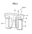
- Fig. 2 is a perspective view of each of the plurality of the fuses 5, 6 and 10 mounted in the fuse box of Fig. 1 .
- the first fuse 5, the second fuse 6 and the fuses 10 have the same construction (however, all of these fuses do not always have the same rated current value), and have the same outer shape (or appearance).
- Each of the fuses 5, 6 and 10 is a so-called blade-type fuse, and comprises a cover member 20 having a generally T-shape when viewed from the front-side thereof, and a pair of parallel plate-like terminals 28 and 28 projecting downwardly respectively from opposite side portions of the cover member 20.
- a fusible element 29 extends between and is formed integrally with the pair of plate-like terminals 28 and 28.
- the cover member 20 of a hollow construction covers the fusible element 29.
- the cover member 20 is made of a colored transparent insulative synthetic resin or the like. Since the cover member 20 is made of the transparent material, whether the fusible element 29 is melted or not can be confirmed with the eyes from a side face thereof, but can hardly be confirmed from a top surface 21 thereof.
- the cover member 20 includes a wide portion 22 of a generally T-shaped cross-section, and narrow portions 23 formed respectively at opposite side portions of the wide portion 22. Engagement portions 24 are formed at the opposite side portions of the wide portion 22, each engagement portion 24 being formed at the step between the wide portion 22 and the narrow portion 23.
- Fig. 3 is a plan view of the fuse box 2 of Fig. 1 .
- the first fuse 5 located at a position such that it can not be viewed in Fig. 3
- the second fuse 6 and the plurality of fuses 10 are detachably received respectively in a plurality of receiving portions 14 including the first receiving portion 15 and the second receiving portion 16, and are juxtaposed such that their top surfaces 21 are disposed flush with one another.
- the fuse puller 30 including as a constituent element the first fuse 5 permanently engaged therewith in fixed relation thereto is provided at the fuse mounting surface 3 of the fuse box 2.
- a general purpose fuse puller 8 is provided at the fuse box 2
- the general purpose fuse puller 8 is a fuse exchange tool for attaching and detaching each of the second fuse 6 and the fuses 10 relative to the fuse box 2, and is formed into a clothespin-like shape so as to grip each fuse 6, 10.
- Fig. 4A is a perspective view of an important portion of the fuse box 2 of Fig. 3 having the fuse puller 30 attached thereto
- Fig. 4B is a perspective view showing the fuse puller 30 alone
- Fig. 5 is an enlarged perspective view showing the fuse puller 30 (that is, a body 33 of this fuse puller 30 alone) with which the first fuse 5 is not yet permanently engaged in fixed relation thereto.
- the fuse puller 30 except the first fuse 5, that is, its body 33, is made of an insulative synthetic resin, and has a base portion 31 at a generally central portion of the body 33.
- a plate-like grip portion 32 is integrally formed (molded) on and projects from a widthwise-central portion of an upper surface of the base portion 31.
- the grip portion 32 has opposite side faces which are so wide as to be gripped by the fingers, and an index 32a (such as a mark) serving also as a non-slip portion is formed by embossing or engraving on at least one of these opposite side faces.
- a permanent engagement portion 35 for permanent engagement with the first fuse 5 in fixed relation thereto is formed (molded) integrally on the base portion 31.
- the permanent engagement portion 35 includes a pair of side walls 35a and 35b formed respectively at opposite side edges of the base portion 31, and extend downwardly from a lower surface of the base portion 31.
- Retaining claws 35c of a rectangular parallelepiped shape are formed on and project from an inner surface of each side wall 35a, 35b.
- the engagement portions 24 of the first fuse 5 are permanently engaged with the upper sides of the retaining claws 35c, so that the permanent engagement portion 35 and the first fuse 5 are permanently fixed to each other.
- a lower surface of each retaining claw 35c is tapering so as to guide the engagement portion 24 of the first fuse 5 to the upper side of the retaining claw 35c.
- the on-board equipments 9 are energized via the first fuse 5, and at this time the inspection of the on-board equipments 9 is effected. After this inspection is finished, the coupler 13 is connected to the connector 12, thereby melting the first fuse 5. Whether the inspection of the on-board equipments 9 is effected via the first fuse 5 alone or via the fuse puller 30 incorporating the first fuse 5 is suitably selected, and in any case the first fuse 5 is permanently fixed to the permanent engagement portion 35 of the fuse puller 30 before the vehicle subjected to the inspection is delivered (shipped) from the vehicle manufacturer.
- all of the plug-in electrical parts including the fuses 5, 6 and 10 are mounted on the fuse box 2, and then the body 33 of the fuse puller 30 is attached to the first fuse 5, and thereafter the fuse box 2 is mounted at a lower portion of an instrument panel within a vehicle compartment, and then the first fuse 5 permanently engaged with the body 33 of the fuse puller 30 is melted.
- the inspector is not required to attach the fuse puller 30 to the first fuse 5 mounted in the fuse box 2 mounted at the lower portion of the instrument panel, and advantageously the body 33 -of the fuse puller 30 can be attached to the first fuse 5 (mounted in the fuse box 2 not yet mounted at the lower portion of the instrument panel), using a machine (which can be used since the lower surface of each retaining claw 35c is tapering), and this is preferred.
- the melted first fuse 5 received in the first receiving portion 15 of the fuse box 2 is exchanged with the second fuse 6 (which is not melted) by the dealer.
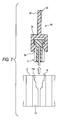
- Figs. 6 and 7 are views explanatory of the fuse exchange method, and Fig. 6 is a cross-sectional view taken along the line VI-VI of Fig. 4A , and Fig. 7 is the view showing the fuse exchange method in which the fuse puller 30 is pulled out of the fuse box 2 of Fig. 6 .
- the first fuse 5 of the fuse puller 30 is received in the first receiving portion 15 of the fuse box 2.
- a groove-like stepped portion 14a (see Fig. 7 ) for holding the wide portion 22 (see Fig. 2 ) of the cover member 20 is formed in each of the receiving portions 14 including the first receiving portion 15, and thanks to the provision of the groove-like stepped portion 14a, the first fuse 5 is detachably held in the receiving portion 14.
- the plate-like terminals 28 of the first fuse 5 are gripped respectively by the connection terminals 15a in the first receiving portion 15, and this also serves to hold the first fuse 5 in the first receiving portion 15.
- the first fuse 5 forms part of the fuse puller 30, and is permanently fixed to the permanent engagement portion 35. More specifically, the retaining claws 35c of the permanent engagement portion 35 of the fuse puller 30 are permanently engaged with the engagement portions 24 of the first fuse 5, so that the permanent engagement portion 35 permanently retains the first fuse 5.
- the body 33 (particularly the grip portion 32) of the fuse puller 30 effectively serves also as an index portion for enabling the first fuse 5 to be easily found.
- the maintenance man or the like of the dealer grips the grip portion 32 of the fuse puller 30 with the fingers, and pulls the fuse puller 30 upward away from the fuse mounting surface 3 of the fuse box 2, and pulls the fuse puller 30 out of the fuse box 2 as shown in Fig. 7 . Thereafter, the maintenance man or the like of the dealer pulls the second fuse 6 out of the second receiving portion 16, using the general purpose fuse puller 8, and inserts this second fuse 6 into the first receiving portion 15, so that the second fuse 6 is held in the first receiving portion 15.
- the maintenance man or the like of the dealer can easily find the position of the second fuse 6 since the second receiving portion 16 is disposed adjacent to the first receiving portion 15 in which the first fuse 5 of the fuse puller 30 is mounted.
- the removed fuse puller 30 having the first fuse 5 is discarded so that it will not be reused by mistake.
- the present invention is not limited to the above embodiment, and suitable modifications, improvements, etc., can be made. Furthermore, the material, shape, dimensions, number, disposition, etc., of each of the constituent elements of the above embodiment are arbitrary and are not limited in so far as the invention can be achieved.
- the second fuse 2 or other fuse which is to be once pulled out can be permanently engaged with a permanent engagement portion of a fuse puller as described above for the fuse puller 30.
- the fuse to be pulled out can be easily found, and can be pulled out of the fuse box.
- the above embodiment may be modified so that the efficiency of the fuse exchange operation can be further enhanced.
- a considerable force is required for pulling the second fuse 6 (held by the groove-like stepped portion 14a and connection terminals in the second receiving portion 16) from the second receiving portion 16 by the use of the general purpose fuse puller 8. Therefore, a modified fuse puller of the invention (and hence a modified electric junction box) which can improve the efficiency of the operation for pulling the second fuse 6 from the fuse box will be described with reference to Figs. 8A to 10 .
- Those constituent elements already described above will be designated by identical or like reference numerals, respectively.
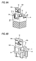
- Fig. 8A is a perspective view of an important portion of a fuse box 2A having the modified fuse puller 30A mounted therein
- Fig. 8B is a perspective view showing the modified fuse puller 30A and the second fuse 6 held (pressed) by a holding portion 37 of the fuse puller 30A against withdrawal from a second receiving portion
- Fig. 9 is a cross-sectional view taken along the tine IX-IX of Fig. 8A
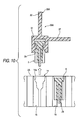
- Fig. 10 is a view showing a method of pulling the modified fuse puller 30A from the fuse box 2A of Fig. 9 .
- the fuse puller 30A except the first fuse 5, that is, its body 33A, is made of an insulative synthetic resin, and has a base portion 31 at a generally central portion of the body 33A.
- a plate-like grip portion 32 is integrally formed (molded) on and projects from a widthwise-central portion of an upper surface of the base portion 31.
- the grip portion 32 has opposite side faces which are so wide as to be gripped by the fingers, and an index 32a (such as a mark) serving also as a non-slip portion is formed by embossing or engraving on at least one of these opposite side faces.
- the plate-like holding portion 37 is integrally formed (molded) on and extends laterally from a central portion of a side face of the base portion 31. This holding portion 37 is provided for abutting against a top surface 21 of the second fuse 6 (received in the second receiving portion 16 disposed in the first receiving portion 15) to hold the second fuse 6:
- a permanent engagement portion 35 for permanent engagement with the first fuse 5 in fixed relation thereto is formed (molded) integrally on the base portion 31.
- the permanent engagement portion 35 includes a pair of side walls 35a and 35b formed respectively at the opposite side edges of the base portion 31, and extend downwardly from a lower surface of the base portion 31.
- Retaining claws 35c of a rectangular parallelepiped shape are formed on and project from an inner surface of each side-wall 35a, 35b.
- the engagement portions 24 of the first fuse 5 are permanently engaged with the upper sides of the retaining claws 35c, so that the permanent engagement portion 35 and the first fuse 5 are permanently fixed to each other.
- a lower surface of each retaining claw 35c is tapering so as to guide the engagement portion 24 of the first fuse 5 to the upper side of the retaining claw 35c.
- the on-board equipments 9 are energized via the first fuse 5, and at this time the inspection of the on-board equipments 9 is effected. After this inspection is finished, the coupler 13 is connected to the connector 12, thereby melting the first fuse 5.
- the inspection of the on-board equipments 9 is effected via the first fuse 5 alone or via the fuse puller 30A incorporating the first fuse 5 is suitably selected.
- the first fuse 5 is permanently fixed -to the permanent engagement portion 35 of the fuse puller 30A before the vehicle subjected to the inspection is delivered (shipped) from the vehicle manufacturer.
- the first fuse 5 of the fuse puller 30A is received in the first receiving portion 15 of the fuse box 2A.
- a groove-like stepped portion 14a (see Fig. 10 ) for holding a wide portion 22 (see Fig. 2 ) of a cover member 20 is formed in each of receiving portions 14 except the second receiving portion 16, and thanks to the provision of the groove-like stepped portion 14a, the first fuse 5 is detachably held in the receiving portion 14. Further, the plate-like terminals 28 of the first fuse 5 are gripped respectively by the connection terminals 15a in the first receiving portion 15, and this also serves to hold the first fuse 5 in the first receiving portion 15.
- plate-like terminals 28 of the second fuse 6 are not gripped by a groove of the second receiving portion 16, and is not firmly held or retained in the second receiving portion 16, but is loosely fitted in the second receiving portion 16.
- the second fuse 6 is pressed downward by the holding portion 37 of the fuse puller 30A, and the cover member 20 of the second fuse 6 is held between the holding portion 37 and a bottom surface disposed at opposite sides of an opening of the groove in the second receiving portion 16 as shown in Fig. 9 , and therefore the second fuse 6 is prevented from disengagement from the second receiving portion 16.
- the first fuse 5 forms part of the fuse puller 30A, and is permanently fixed to the permanent engagement portion 35. More specifically, the retaining claws 35c of the permanent engagement portion 35 of the fuse puller 30A are permanently engaged with the engagement portions 24 of the first fuse 5, so that the permanent engagement portion 35 permanently retains the first fuse 5.
- the body 33A (particularly the grip portion 32) of the fuse puller 30A effectively serves also as an index portion for enabling the first fuse 5 to be easily found.
- the maintenance man or the like of the dealer grips the grip portion 32 of the fuse puller 30A with the fingers, and pulls the fuse puller 30A upward away from the fuse mounting surface 3 of the fuse box 2A, and pulls the fuse puller 30A out of the fuse box 2A as shown in Fig. 10 , and at this time the holding of the second fuse 6 in the second receiving portion 16 by the holding portion 37 is canceled. Thereafter, the maintenance man or the like of the dealer pulls the second fuse 6 out of the second receiving portion 16, using the general purpose fuse puller 8.
- the maintenance man or the like of the dealer can easily take the second fuse 6 out of the second receiving portion 16 without using a large force, since the second fuse 6 is loosely fitted in the second receiving portion 16. Then, the maintenance man or the like of the dealer inserts the second fuse 6 (gripped by the general purpose fuse puller 8) into the first receiving portion 15, so that the second fuse 6 is held in this first receiving portion 15. At this time, the maintenance man or the like of the dealer can easily find the position of the second fuse 6 since the second receiving portion 16 is disposed adjacent to the first receiving portion 15 in which the first fuse 5 of the fuse puller 30A is mounted. The removed fuse puller 30A having the first fuse 5 is discarded so that it will not be reused by mistake.
- the fuse i.e., the first fuse 5, the second fuse 6, etc.
- the fuse puller 30 (30A) in fixed relation thereto.
- the fuse does not always need to be permanently engaged with the fuse puller body in fixed relation thereto.
- the above embodiment of the present invention is directed to the fuse box (electric junction box), the invention can be applied to any other suitable electric junction box and the like such as a power box, a relay box, an electronic control unit box, etc., in so far as a plurality of fuses are detachably received in a plurality of receiving portions in a juxtaposed manner.
- the illustrated shape of the fuses used in the above embodiment is one example, and any other suitable fuses can be used in the invention.
- the illustrated shape of the fuse receiving portions of the fuse box in the above embodiment is one example, and the fuse receiving portions can have any other suitable shape.
- the fuse pullers of the invention are not limited to the illustrated shapes, and can have any other suitable shape without departing from the subject manner of the invention.
Landscapes
- Fuses (AREA)
- Connection Or Junction Boxes (AREA)
Abstract
Description
- This invention relates to an improved fuse puller and an improved electric junction box (i.e., an electric junction block).
- At a place where vehicles such as automobiles are produced, an inspection such as electrical connection testing for on-board equipments mounted on the vehicle is carried out, and thereafter only those vehicles which have passed this inspection are delivered to dealers. Generally, a vehicle is equipped with on-board equipments (hereinafter referred to as "normally-energized equipments"), such as a clock, a room lamp, etc., which are always supplied with electric power from a battery regardless of the position of an ignition key. Therefore, when the vehicle is stored for a long time after the above inspection, a dark current continues to flow through the above normally-energized equipments for a long time, and there is a possibility that a battery serving as a power source may be exhausted or dead before the vehicle is delivered to a dealer.
- To overcome this problem, there has been adopted a method in which a dark current fuse is provided in an electric wire electrically connecting the power source to the normally-energized equipments, and after the inspection is carried out, an inspector removes the dark current fuse, and thereafter at the time when maintenance of the vehicle is effected by the dealer so that the vehicle can be delivered to the user, a maintenance man or the like of the dealer again attaches a fuse to an electric junction box such as a fuse box.
- However, generally, the electric junction box such as the fuse box to which the above dark current fuse is attached is mounted at a lower portion of an instrument panel within a car compartment, and therefore it is not easy for an inspector to remove the dark current fuse from the electric junction box in an inspection line. Therefore, there has been proposed a technique in which instead of removing the dark current fuse, the dark current fuse is melted after the inspection is finished (see, for example, Patent Literature 1). In this proposed technique, a coupler for melting purposes is attached to a connector of a wire harness extending from the electric junction box, thereby melting the dark current fuse.
- However, even when this technique is adopted, it is necessary for the dealer to remove the melted dark current fuse (i.e., the old fuse) and then to insert a new fuse for exchange purposes. More specifically, the old fuse mounted in a first receiving portion of the electric junction box is gripped by a fuse puller and is pulled therefrom by this fuse puller, and then is discarded. Thereafter, the new fuse mounted in a second receiving portion is gripped by the fuse puller, and is removed therefrom by the above fuse puller, and is inserted into the first receiving portion. Thus, the maintenance man or the like of the dealer is required to effect a series of steps of such cumbersome fuse exchange operation. The fuse puller is held as standard equipment in a fuse puller holding portion (which is provided merely for the purpose of holding the fuse puller) within the electric junction box.
- [Patent Literature 1]
JP-A-2006-304434 - In the electric junction box having the melted dark current fuse mounted therein, many other fuses than the dark current fuse which have the same outer shape as the dark current fuse are arranged together with the dark current fuse in a juxtaposed manner. Namely, a fuse mounting surface of the electric junction box is such that it is difficult to identify, from the appearance, the melted dark current fuse among the plurality of juxtaposed fuses.
- Here, even if the position of the melted dark current fuse in the electric junction box is predetermined, there is not provided the situation in which anyone such as the maintenance man of the dealer can find and remove the melted dark current fuse soon after start of the fuse exchange operation regardless of his skill in carrying out this fuse exchange operation. Therefore, much time was required for the fuse exchange operation. And besides, there is a possibility that the maintenance man or the like of the dealer may mistake some other fuse for the melted dark current fuse, and in such a case the fuse exchange operation must be carried out again.
- When there is provided a parallel receiving portion electrically connected in parallel with the first receiving portion as in the technique of Patent Literature 1, it is only necessary to mount the new fuse in the parallel receiving portion, and the melted dark current fuse does not need to be removed from the first receiving portion: However, when the melted dark current fuse remains in the electric junction box, it is feared that the user of the vehicle may feel uneasy, and therefore it is preferred to remove this dark current fuse from the electric junction box.
- Thus, although the melted dark current fuse or other fuse should be removed from the electric junction box, it has been difficult to easily find the relevant fuse and to remove it.
- This invention has been made in view of the above circumstances, and an object of the invention is to provide a fuse puller and an electric junction box, in which a fuse exchange operation can be carried out easily and positively.
- The above object has been achieved by a fuse puller of the present invention having features recited in the following Paragraphs (1) to (3).
- (1) A fuse puller comprises:
- a body; and
- a first fuse that is permanently engaged with the body in fixed relation thereto.
- (2) In the fuse puller of the above Paragraph (1), the first fuse has a fusible element which is melted.
- (3) In the fuse puller of the above Paragraph (1) or Paragraph (2), the body includes a permanent engagement portion which is permanently engaged with the first fuse, and a holding portion which holds a second fuse against an electric junction box. The second fuse is received in the electric junction box in adjoining relation to the first fuse received in the electric junction box.
In the fuse puller of the above Paragraph (1), the body of the fuse puller is conspicuous at the fuse mounting surface at which the plurality of fuses including the first fuse are arranged in a juxtaposed manner, and therefore the first fuse which is to be removed can be easily found out among the plurality of fuses, and therefore a fuse exchange operation can be carried out easily and positively. Here, the first fuse may or may not be in a melted condition.
In the fuse puller of the above Paragraph (2), an operation for exchanging the melted first fuse can be carried out easily and positively.
In the fuse puller of the above Paragraph (3), even when the second fuse is loosely fitted in the electric junction box, the second fuse can be positively retained in the electric junction box.
The above object has also been achieved by an electric junction box having features recited in the following Paragraphs (4) to (8). - (4) A electric junction box comprises:
- a fuse puller that includes a body and a first fuse which is engaged with the body; and
- a fuse mounting surface to which a plurality of fuses including the first fuse are mounted so as to be arranged in parallel to each other.
- (5) In the electric junction box of the above Paragraph (4), the first fuse is permanently engaged with the body in fixed relation thereto.
- (6) In the electric junction box of the above Paragraph (4) and Paragraph (5), the first fuse has a fusible element which is melted.
- (7) In the electric junction box of any one of the above Paragraphs (4) to (6), the body includes an engagement portion which is engaged with the first fuse, and a holding portion which holds a second fuse loosely fitted in a second receiving portion disposed adjacent to the first fuse held in a first receiving portion of the fuse mounting surface.
- (8) In the electric junction box of any one of the above Paragraphs (4) to (7), the plurality of fuses including the first fuse have the same outer shape.
- In the electric junction box of the above Paragraph (4), the body of the fuse puller is conspicuous at the fuse mounting surface at which the plurality of fuses including the first fuse are arranged in a juxtaposed manner, and therefore the first fuse which is to be removed can be easily found out among the plurality of fuses, and therefore the fuse exchange operation can be carried out easily and positively. Here, the first fuse may or may not be in a melted condition.
- In the electric junction box of the above Paragraph (5), the first fuse will not be disengaged from the body of the fuse puller, and this is desirable.
- In the electric junction box of the above Paragraph (6), the operation for exchanging the melted first fuse can be carried out easily and positively. In addition, the melted first fuse is permanently engaged with the body of the fuse puller in fixed relation thereto, and this eliminates a possibility that the melted first fuse is disengaged from the electric junction box, and is reused by mistake.
- In the electric junction box of the above Paragraph (7), even when the second fuse is loosely fitted in the electric junction box, the second fuse can be positively retained in the electric junction box. In this case, when the first fuse is in a melted condition, and the second fuse is an exchange fuse for exchange with this melted first fuse, then the fuse exchange operation can be carried out smoothly.
- In the electric junction box of the above Paragraph (8), the first fuse which is to be removed can be easily found out among the plurality of fuses having the same outer shape, and therefore the fuse exchange operation can be carried out easily and positively.
- In the present invention, the fuse (that is, the fuse engaged with the body of the fuse puller) which is to be removed can be easily found out among the plurality of fuses arranged in a juxtaposed manner in the electric junction box, and therefore the fuse exchange operation can be carried out easily and positively. Therefore, in the present invention, the time and labor required for the fuse exchange operation can be reduced.
- The present invention has been briefly described above. Details of the invention will become more manifest upon reading the following Section "Best Mode for Carrying Out the Invention" with reference to the accompanying drawings.
- The above objects and advantages of the present invention will become more apparent by describing in detail preferred exemplary embodiments thereof with reference to the accompanying drawings, wherein:
-
Fig. 1 is a circuit diagram of one preferred embodiment of a fuse box (electric junction box) of the present invention; -
Fig. 2 is a perspective view of one of a plurality of fuses to be mounted in the fuse box ofFig. 1 ; -
Fig. 3 is a plan view of the fuse box ofFig. 1 ; -
Fig. 4A is a perspective view of an important portion of the fuse box ofFig. 3 in which a fuse puller of the invention incorporating the fuse ofFig. 2 is mounted, andFig. 4B is a perspective view showing the fuse puller alone; -
Fig. 5 is an enlarged perspective view of the fuse puller ofFig. 4B with which the fuse is not yet permanently engaged in fixed relation thereto; -
Fig. 6 is a cross-sectional view taken along the line VI-VI ofFig. 4A ; -
Fig. 7 is a view showing a fuse exchange method in which the fuse puller is pulled out of the fuse box ofFig. 6 ; -
Fig. 8A is a perspective view of an important portion of a fuse box in which a modified fuse puller of the invention is mounted, andFig. 8B is a perspective view showing the modified fuse puller ofFig. 8A and a second fuse held by a holding portion of the fuse puller against withdrawal from a second receiving portion; -
Fig. 9 is a cross-sectional view taken along the line IX-IX ofFig. 8A ; and -
Fig. 10 is a view showing a fuse exchange method in which the modified fuse puller is pulled out of thefuse box 2A ofFig. 9 . - A preferred embodiment of the present invention will now be described with reference to the drawings.
-
Fig. 1 is a circuit diagram of one preferred embodiment of a fuse box (electric junction box) of the invention. Awire 11 extending from abattery 4 serving as a power source of a vehicle branches into a plurality ofwires 11a, and is connected to various on-board equipments (normally-energized equipments) 9 (9-1, 9-2, 9-3, 9-4, 9-5, 9-6 and 9-7).Fuses 10 are provided at thebranch wires 11 a so as to prevent an excess current from flowing through the on-board equipments 9. Afirst fuse 5 is provided at that portion of thewire 11 disposed upstream of thebranch wires 11 a , and is adapted to be forcibly melted so as to prevent a dark current from flowing through the on-board equipments 9. - The
first fuse 5, together with the plurality offuses 10, is mounted in afuse box 2. Thefirst fuse 5 is a fuse which forms part of one preferred embodiment of a fuse puller of the invention and is detachably received in a first receivingportion 15 of thefuse box 2.Connection terminals first fuse 5 to thewire 11 are provided in the first receivingportion 15. Asecond fuse 6 is detachably received in a second receivingportion 16 disposed adjacent to the first receivingportion 15. Thissecond fuse 6 is not electrically connected to thewire 11. - On the other hand, the
wire 11 is branched downstream of the first receivingportion 15, and this branch wire is led out to the exterior of thefuse box 2, and is electrically connected to aconnector 12. When a coupler 13 is connected to thisconnector 12, thewire 11 downstream of the first receivingportion 15 is grounded (that is, connected to the ground). As a result, an excess current flows through thewire 11, so that thefirst fuse 5 is melted. -
Fig. 2 is a perspective view of each of the plurality of thefuses Fig. 1 . Thefirst fuse 5, thesecond fuse 6 and thefuses 10 have the same construction (however, all of these fuses do not always have the same rated current value), and have the same outer shape (or appearance). Each of thefuses cover member 20 having a generally T-shape when viewed from the front-side thereof, and a pair of parallel plate-like terminals cover member 20. A fusible element 29 extends between and is formed integrally with the pair of plate-like terminals cover member 20 of a hollow construction covers the fusible element 29. - The
cover member 20 is made of a colored transparent insulative synthetic resin or the like. Since thecover member 20 is made of the transparent material, whether the fusible element 29 is melted or not can be confirmed with the eyes from a side face thereof, but can hardly be confirmed from atop surface 21 thereof. Thecover member 20 includes a wide portion 22 of a generally T-shaped cross-section, andnarrow portions 23 formed respectively at opposite side portions of the wide portion 22.Engagement portions 24 are formed at the opposite side portions of the wide portion 22, eachengagement portion 24 being formed at the step between the wide portion 22 and thenarrow portion 23. -
Fig. 3 is a plan view of thefuse box 2 ofFig. 1 . At afuse mounting surface 3 of thefuse box 2 ofFig. 3 , the first fuse 5 (located at a position such that it can not be viewed inFig. 3 ), thesecond fuse 6 and the plurality offuses 10 are detachably received respectively in a plurality of receivingportions 14 including the first receivingportion 15 and the second receivingportion 16, and are juxtaposed such that theirtop surfaces 21 are disposed flush with one another. Thefuse puller 30 including as a constituent element thefirst fuse 5 permanently engaged therewith in fixed relation thereto is provided at thefuse mounting surface 3 of thefuse box 2. - Also, a general
purpose fuse puller 8 is provided at thefuse box 2 The generalpurpose fuse puller 8 is a fuse exchange tool for attaching and detaching each of thesecond fuse 6 and thefuses 10 relative to thefuse box 2, and is formed into a clothespin-like shape so as to grip eachfuse -
Fig. 4A is a perspective view of an important portion of thefuse box 2 ofFig. 3 having thefuse puller 30 attached thereto, andFig. 4B is a perspective view showing thefuse puller 30 alone.Fig. 5 is an enlarged perspective view showing the fuse puller 30 (that is, abody 33 of thisfuse puller 30 alone) with which thefirst fuse 5 is not yet permanently engaged in fixed relation thereto. - The
fuse puller 30 except thefirst fuse 5, that is, itsbody 33, is made of an insulative synthetic resin, and has abase portion 31 at a generally central portion of thebody 33. A plate-like grip portion 32 is integrally formed (molded) on and projects from a widthwise-central portion of an upper surface of thebase portion 31. Thegrip portion 32 has opposite side faces which are so wide as to be gripped by the fingers, and anindex 32a (such as a mark) serving also as a non-slip portion is formed by embossing or engraving on at least one of these opposite side faces. Apermanent engagement portion 35 for permanent engagement with thefirst fuse 5 in fixed relation thereto is formed (molded) integrally on thebase portion 31. - More specifically, the
permanent engagement portion 35 includes a pair ofside walls base portion 31, and extend downwardly from a lower surface of thebase portion 31. Retainingclaws 35c of a rectangular parallelepiped shape are formed on and project from an inner surface of eachside wall engagement portions 24 of thefirst fuse 5 are permanently engaged with the upper sides of the retainingclaws 35c, so that thepermanent engagement portion 35 and thefirst fuse 5 are permanently fixed to each other. A lower surface of each retainingclaw 35c is tapering so as to guide theengagement portion 24 of thefirst fuse 5 to the upper side of the retainingclaw 35c. - Next, inspection of the on-board equipments, transport of the vehicle, and a method of exchanging the fuse will be briefly described with reference to
Figs. 1 and3 . - First, in an inspection line at a vehicle production site of a vehicle manufacturer, the on-
board equipments 9 are energized via thefirst fuse 5, and at this time the inspection of the on-board equipments 9 is effected. After this inspection is finished, the coupler 13 is connected to theconnector 12, thereby melting thefirst fuse 5. Whether the inspection of the on-board equipments 9 is effected via thefirst fuse 5 alone or via thefuse puller 30 incorporating thefirst fuse 5 is suitably selected, and in any case thefirst fuse 5 is permanently fixed to thepermanent engagement portion 35 of thefuse puller 30 before the vehicle subjected to the inspection is delivered (shipped) from the vehicle manufacturer. However, preferably, all of the plug-in electrical parts including thefuses fuse box 2, and then thebody 33 of thefuse puller 30 is attached to thefirst fuse 5, and thereafter thefuse box 2 is mounted at a lower portion of an instrument panel within a vehicle compartment, and then thefirst fuse 5 permanently engaged with thebody 33 of thefuse puller 30 is melted. With this mounting method, the inspector is not required to attach thefuse puller 30 to thefirst fuse 5 mounted in thefuse box 2 mounted at the lower portion of the instrument panel, and advantageously the body 33 -of thefuse puller 30 can be attached to the first fuse 5 (mounted in thefuse box 2 not yet mounted at the lower portion of the instrument panel), using a machine (which can be used since the lower surface of each retainingclaw 35c is tapering), and this is preferred. - Then, the vehicle in this condition is transported from the vehicle manufacturer to a dealer. Therefore, a dark current is prevented from flowing through the on-
board equipments 9. - Then, the melted
first fuse 5 received in the first receivingportion 15 of thefuse box 2 is exchanged with the second fuse 6 (which is not melted) by the dealer. - The method of exchanging the fuse will be described in further detail with reference to
Figs. 6 and7 .Figs. 6 and7 are views explanatory of the fuse exchange method, andFig. 6 is a cross-sectional view taken along the line VI-VI ofFig. 4A , andFig. 7 is the view showing the fuse exchange method in which thefuse puller 30 is pulled out of thefuse box 2 ofFig. 6 . - As shown in
Fig. 6 , thefirst fuse 5 of thefuse puller 30 is received in the first receivingportion 15 of thefuse box 2. A groove-like steppedportion 14a (seeFig. 7 ) for holding the wide portion 22 (seeFig. 2 ) of thecover member 20 is formed in each of the receivingportions 14 including the first receivingportion 15, and thanks to the provision of the groove-like steppedportion 14a, thefirst fuse 5 is detachably held in the receivingportion 14. Furthermore, the plate-like terminals 28 of thefirst fuse 5 are gripped respectively by theconnection terminals 15a in the first receivingportion 15, and this also serves to hold thefirst fuse 5 in the first receivingportion 15. - As described above, the
first fuse 5 forms part of thefuse puller 30, and is permanently fixed to thepermanent engagement portion 35. More specifically, the retainingclaws 35c of thepermanent engagement portion 35 of thefuse puller 30 are permanently engaged with theengagement portions 24 of thefirst fuse 5, so that thepermanent engagement portion 35 permanently retains thefirst fuse 5. - Therefore, immediately after a maintenance man or the like of the dealer looks at the
fuse mounting surface 3 of thefuse box 2, he can easily find the body 33 (particularly the grip portion 32) of thefuse puller 30 among the plurality of fuses (that is, thefuses 10 and the second fuse 6) with theirtop surfaces 21 disposed flush with one another. Thus, the body 33 (particularly the grip portion 32) of thefuse puller 30 effectively serves also as an index portion for enabling thefirst fuse 5 to be easily found. - When the
first fuse 5 is to be removed, the maintenance man or the like of the dealer grips thegrip portion 32 of thefuse puller 30 with the fingers, and pulls thefuse puller 30 upward away from thefuse mounting surface 3 of thefuse box 2, and pulls thefuse puller 30 out of thefuse box 2 as shown inFig. 7 . Thereafter, the maintenance man or the like of the dealer pulls thesecond fuse 6 out of the second receivingportion 16, using the generalpurpose fuse puller 8, and inserts thissecond fuse 6 into the first receivingportion 15, so that thesecond fuse 6 is held in the first receivingportion 15. At this time, the maintenance man or the like of the dealer can easily find the position of thesecond fuse 6 since the second receivingportion 16 is disposed adjacent to the first receivingportion 15 in which thefirst fuse 5 of thefuse puller 30 is mounted. The removedfuse puller 30 having thefirst fuse 5 is discarded so that it will not be reused by mistake. - The present invention is not limited to the above embodiment, and suitable modifications, improvements, etc., can be made. Furthermore, the material, shape, dimensions, number, disposition, etc., of each of the constituent elements of the above embodiment are arbitrary and are not limited in so far as the invention can be achieved.
- For example, the
second fuse 2 or other fuse which is to be once pulled out can be permanently engaged with a permanent engagement portion of a fuse puller as described above for thefuse puller 30. In this case, also, the fuse to be pulled out can be easily found, and can be pulled out of the fuse box. - The above embodiment may be modified so that the efficiency of the fuse exchange operation can be further enhanced. In the above fuse exchange method, a considerable force is required for pulling the second fuse 6 (held by the groove-like stepped
portion 14a and connection terminals in the second receiving portion 16) from the second receivingportion 16 by the use of the generalpurpose fuse puller 8. Therefore, a modified fuse puller of the invention (and hence a modified electric junction box) which can improve the efficiency of the operation for pulling thesecond fuse 6 from the fuse box will be described with reference toFigs. 8A to 10 . Those constituent elements already described above will be designated by identical or like reference numerals, respectively. -
Fig. 8A is a perspective view of an important portion of afuse box 2A having the modifiedfuse puller 30A mounted therein,Fig. 8B is a perspective view showing the modifiedfuse puller 30A and thesecond fuse 6 held (pressed) by a holdingportion 37 of thefuse puller 30A against withdrawal from a second receivingportion 16,Fig. 9 is a cross-sectional view taken along the tine IX-IX ofFig. 8A , andFig. 10 is a view showing a method of pulling the modifiedfuse puller 30A from thefuse box 2A ofFig. 9 . - The
fuse puller 30A except thefirst fuse 5, that is, itsbody 33A, is made of an insulative synthetic resin, and has abase portion 31 at a generally central portion of thebody 33A. A plate-like grip portion 32 is integrally formed (molded) on and projects from a widthwise-central portion of an upper surface of thebase portion 31. Thegrip portion 32 has opposite side faces which are so wide as to be gripped by the fingers, and anindex 32a (such as a mark) serving also as a non-slip portion is formed by embossing or engraving on at least one of these opposite side faces. The plate-like holding portion 37 is integrally formed (molded) on and extends laterally from a central portion of a side face of thebase portion 31. This holdingportion 37 is provided for abutting against atop surface 21 of the second fuse 6 (received in the second receivingportion 16 disposed in the first receiving portion 15) to hold the second fuse 6: - A
permanent engagement portion 35 for permanent engagement with thefirst fuse 5 in fixed relation thereto is formed (molded) integrally on thebase portion 31. As shown inFigs. 9 and10 , thepermanent engagement portion 35 includes a pair ofside walls base portion 31, and extend downwardly from a lower surface of thebase portion 31. Retainingclaws 35c of a rectangular parallelepiped shape are formed on and project from an inner surface of each side-wall engagement portions 24 of thefirst fuse 5 are permanently engaged with the upper sides of the retainingclaws 35c, so that thepermanent engagement portion 35 and thefirst fuse 5 are permanently fixed to each other. A lower surface of each retainingclaw 35c is tapering so as to guide theengagement portion 24 of thefirst fuse 5 to the upper side of the retainingclaw 35c. - Next, inspection of the on-board equipments, transport of the vehicle, and a method of exchanging the fuse by the use of the
fuse puller 30A will be briefly described with reference toFigs. 1 and3 . - First, in the inspection line at the vehicle production site of the vehicle manufacturer, the on-
board equipments 9 are energized via thefirst fuse 5, and at this time the inspection of the on-board equipments 9 is effected. After this inspection is finished, the coupler 13 is connected to theconnector 12, thereby melting thefirst fuse 5. Whether the inspection of the on-board equipments 9 is effected via thefirst fuse 5 alone or via thefuse puller 30A incorporating thefirst fuse 5 is suitably selected. However, it is preferred to permanently engage thefirst fuse 5 with thebody 33A of thefuse puller 30A after thefirst fuse 5 is melted, in which case advantageously a melted condition of a fusible element 29 of thefirst fuse 5 can be confirmed with the eyes. In any case, thefirst fuse 5 is permanently fixed -to thepermanent engagement portion 35 of thefuse puller 30A before the vehicle subjected to the inspection is delivered (shipped) from the vehicle manufacturer. - Then, the vehicle in this condition is transported from the vehicle manufacturer to a dealer. Therefore, a dark current is prevented from flowing through the on-
board equipments 9. - Then, the melted
first fuse 5 received in the first receivingportion 15 of thefuse box 2A is exchanged with the second fuse 6 (which is not melted) by the dealer. This fuse exchange method will be described in further detail with reference toFigs. 9 and10 . - As shown in
Fig. 9 , thefirst fuse 5 of thefuse puller 30A is received in the first receivingportion 15 of thefuse box 2A. A groove-like steppedportion 14a (seeFig. 10 ) for holding a wide portion 22 (seeFig. 2 ) of acover member 20 is formed in each of receivingportions 14 except the second receivingportion 16, and thanks to the provision of the groove-like steppedportion 14a, thefirst fuse 5 is detachably held in the receivingportion 14. Further, the plate-like terminals 28 of thefirst fuse 5 are gripped respectively by theconnection terminals 15a in the first receivingportion 15, and this also serves to hold thefirst fuse 5 in the first receivingportion 15. - On the other hand, plate-
like terminals 28 of thesecond fuse 6 are not gripped by a groove of the second receivingportion 16, and is not firmly held or retained in the second receivingportion 16, but is loosely fitted in the second receivingportion 16. In this case, thesecond fuse 6 is pressed downward by the holdingportion 37 of thefuse puller 30A, and thecover member 20 of thesecond fuse 6 is held between the holdingportion 37 and a bottom surface disposed at opposite sides of an opening of the groove in the second receivingportion 16 as shown inFig. 9 , and therefore thesecond fuse 6 is prevented from disengagement from the second receivingportion 16. - The
first fuse 5 forms part of thefuse puller 30A, and is permanently fixed to thepermanent engagement portion 35. More specifically, the retainingclaws 35c of thepermanent engagement portion 35 of thefuse puller 30A are permanently engaged with theengagement portions 24 of thefirst fuse 5, so that thepermanent engagement portion 35 permanently retains thefirst fuse 5. - Therefore, immediately after the maintenance man or the like of the dealer looks at the
fuse mounting surface 3 of thefuse box 2A, he can easily find thebody 33A (particularly the grip portion 32) of thefuse puller 30A among the plurality of juxtaposed fuses 10 with theirtop surfaces 21 disposed flush with one another. Thus, thebody 33A (particularly the grip portion 32) of thefuse puller 30A effectively serves also as an index portion for enabling thefirst fuse 5 to be easily found. - When the
first fuse 5 is to be removed, the maintenance man or the like of the dealer grips thegrip portion 32 of thefuse puller 30A with the fingers, and pulls thefuse puller 30A upward away from thefuse mounting surface 3 of thefuse box 2A, and pulls thefuse puller 30A out of thefuse box 2A as shown inFig. 10 , and at this time the holding of thesecond fuse 6 in the second receivingportion 16 by the holdingportion 37 is canceled. Thereafter, the maintenance man or the like of the dealer pulls thesecond fuse 6 out of the second receivingportion 16, using the generalpurpose fuse puller 8. At this time, the maintenance man or the like of the dealer can easily take thesecond fuse 6 out of the second receivingportion 16 without using a large force, since thesecond fuse 6 is loosely fitted in the second receivingportion 16. Then, the maintenance man or the like of the dealer inserts the second fuse 6 (gripped by the general purpose fuse puller 8) into the first receivingportion 15, so that thesecond fuse 6 is held in this first receivingportion 15. At this time, the maintenance man or the like of the dealer can easily find the position of thesecond fuse 6 since the second receivingportion 16 is disposed adjacent to the first receivingportion 15 in which thefirst fuse 5 of thefuse puller 30A is mounted. The removedfuse puller 30A having thefirst fuse 5 is discarded so that it will not be reused by mistake. - In the electric junction box (i.e., the fuse box 2) of the above embodiment and the modified electric junction box (i.e., the
fuse box 2A), the fuse (i.e., thefirst fuse 5, thesecond fuse 6, etc.) to be removed is permanently engaged with the body 33 (33A) of the fuse puller 30 (30A) in fixed relation thereto. However, when attention need to be directed only to the index portion for enabling the relevant fuse to be easily found at thefuse mounting surface 3 at which the plurality of fuses are arranged in a juxtaposed manner, the fuse does not always need to be permanently engaged with the fuse puller body in fixed relation thereto. - Although the above embodiment of the present invention is directed to the fuse box (electric junction box), the invention can be applied to any other suitable electric junction box and the like such as a power box, a relay box, an electronic control unit box, etc., in so far as a plurality of fuses are detachably received in a plurality of receiving portions in a juxtaposed manner.
- The illustrated shape of the fuses used in the above embodiment is one example, and any other suitable fuses can be used in the invention. Furthermore, the illustrated shape of the fuse receiving portions of the fuse box in the above embodiment is one example, and the fuse receiving portions can have any other suitable shape. The fuse pullers of the invention are not limited to the illustrated shapes, and can have any other suitable shape without departing from the subject manner of the invention.
- Although the invention has been illustrated and described for the particular preferred embodiments, it is apparent to a person skilled in the art that various changes and modifications can be made on the basis of the teachings of the invention. It is apparent that such changes and modifications are within the spirit, scope, and intention of the invention as defined by the appended claims.
- The present application is based on Japan Patent Application No.
2007-256663 filed on September 28, 2007
Claims (8)
- A fuse puller comprising:a body; anda first fuse that is permanently engaged with the body in fixed relation thereto.
- The fuse puller according to claim 1, wherein the first fuse has a fusible element which is melted.
- The fuse puller according to claim 1, wherein the body includes:a permanent engagement portion which is permanently engaged with the first fuse; anda holding portion which holds a second fuse against an electric junction box; and
wherein the second fuse is received in the electric junction box in adjoining relation to the first fuse received in the electric junction box. - A electric junction box comprising:a fuse puller that includes a body and a first fuse which is engaged with the body; anda fuse mounting surface to which a plurality of fuses including the first fuse are mounted so as to be arranged in parallel to each other.
- The electric junction box according to claim 4, wherein the first fuse is permanently engaged with the body in fixed relation thereto.
- The electric junction box according to claim 4, wherein the first fuse has a fusible element which is melted.
- The electric junction box according to claim 4, wherein the body includes:an engagement portion which is engaged with the first fuse; anda holding portion which holds a second fuse loosely fitted in a second receiving portion disposed adjacent to the first fuse held in a first receiving portion of the fuse mounting surface.
- The electric junction box according to claim 4, wherein the plurality of fuses including the first fuse have the same outer shape.
Applications Claiming Priority (1)
| Application Number | Priority Date | Filing Date | Title |
|---|---|---|---|
| JP2007256663A JP4472741B2 (en) | 2007-09-28 | 2007-09-28 | Fuse puller and electrical junction box |
Publications (3)
| Publication Number | Publication Date |
|---|---|
| EP2043128A2 true EP2043128A2 (en) | 2009-04-01 |
| EP2043128A3 EP2043128A3 (en) | 2010-02-17 |
| EP2043128B1 EP2043128B1 (en) | 2012-11-07 |
Family
ID=40120118
Family Applications (1)
| Application Number | Title | Priority Date | Filing Date |
|---|---|---|---|
| EP08016995A Not-in-force EP2043128B1 (en) | 2007-09-28 | 2008-09-26 | Fuse puller and electric junction box |
Country Status (4)
| Country | Link |
|---|---|
| US (1) | US20090088026A1 (en) |
| EP (1) | EP2043128B1 (en) |
| JP (1) | JP4472741B2 (en) |
| CN (1) | CN101399140B (en) |
Cited By (2)
| Publication number | Priority date | Publication date | Assignee | Title |
|---|---|---|---|---|
| CN105206482A (en) * | 2015-10-20 | 2015-12-30 | 无锡格莱德科技有限公司 | Automobile electric box fuse jig |
| DE102011006144B4 (en) | 2010-03-26 | 2019-06-27 | Yazaki Corp. | Mounting structure for a component equipped with a bracket |
Families Citing this family (7)
| Publication number | Priority date | Publication date | Assignee | Title |
|---|---|---|---|---|
| KR101373727B1 (en) * | 2007-10-02 | 2014-03-13 | 타이코에이엠피(유) | The fastening device of the low profile fuse for a vehicle |
| JP5606200B2 (en) * | 2010-07-23 | 2014-10-15 | 矢崎総業株式会社 | Fuse block device |
| JP6345999B2 (en) * | 2014-06-25 | 2018-06-20 | 矢崎総業株式会社 | Power switch, feeder circuit and electrical junction box |
| US9702921B2 (en) | 2014-11-11 | 2017-07-11 | Dustin Scabarozi | Multi-purpose tool for blade fuses |
| JP6262178B2 (en) * | 2015-09-03 | 2018-01-17 | 矢崎総業株式会社 | Electrical junction box |
| CN107658608A (en) * | 2017-10-27 | 2018-02-02 | 镇江科胜电子科技有限公司 | A kind of built-in electronic connector |
| CN112271125B (en) * | 2020-09-23 | 2025-03-18 | 国网河北省电力有限公司邯郸市峰峰矿区供电分公司 | Square Ceramic Fuse Removal Device |
Citations (2)
| Publication number | Priority date | Publication date | Assignee | Title |
|---|---|---|---|---|
| JP2006304434A (en) | 2005-04-18 | 2006-11-02 | Honda Motor Co Ltd | Electrical junction box for vehicles |
| JP2007256663A (en) | 2006-03-23 | 2007-10-04 | Brother Ind Ltd | Developing cartridge, image carrier unit, and image forming apparatus |
Family Cites Families (16)
| Publication number | Priority date | Publication date | Assignee | Title |
|---|---|---|---|---|
| US1922500A (en) * | 1930-04-21 | 1933-08-15 | Clarence G Pierce | Fuse holder |
| US3775724A (en) * | 1973-03-05 | 1973-11-27 | Gen Motors Corp | Circuit protector |
| US4094212A (en) * | 1977-04-07 | 1978-06-13 | Fischer & Porter Company | Fuse-mate |
| US4164726A (en) * | 1977-08-01 | 1979-08-14 | Weibe Gerald L | Encapsulated plug-in electrically conducting component |
| US4541311A (en) * | 1982-05-03 | 1985-09-17 | Idea Pioneer, Inc. | Fuse puller |
| JP2879811B2 (en) * | 1993-07-02 | 1999-04-05 | 矢崎総業株式会社 | Intermittent mechanism of dark current fuse and electric junction box provided with the same |
| US5418515A (en) * | 1993-12-22 | 1995-05-23 | Reyes; Daniel | Fuse interruption indicator and integral extractor |
| US5409402A (en) * | 1994-05-03 | 1995-04-25 | Ball; Roger M. | Plug-in fuse device with interchangeable fuse elements |
| US5666865A (en) * | 1994-11-02 | 1997-09-16 | Sumitomo Wiring Systems, Ltd. | Fuse puller |
| US6033252A (en) * | 1998-01-14 | 2000-03-07 | Lear Automotive Dearborn, Inc. | Component retaining device |
| US6107908A (en) * | 1998-08-17 | 2000-08-22 | Santa Cruz; Cathy D. | Blown fuse commutator strip and method of use |
| DE10084558T1 (en) * | 2000-03-07 | 2003-04-24 | Furukawa Electric Co Ltd | Electrical junction box |
| US6522234B1 (en) * | 2000-08-14 | 2003-02-18 | Edward G. Sturgill | Plug-in fuse |
| US6406331B1 (en) * | 2001-07-19 | 2002-06-18 | Yazaki North America | Fuse holder with positive removal feature |
| DE10330263B3 (en) * | 2003-07-04 | 2005-03-03 | Lisa Dräxlmaier GmbH | Device for extracting or inserting a fuse |
| US6871567B2 (en) * | 2003-08-01 | 2005-03-29 | Lear Corporation | Fuse and relay puller |
-
2007
- 2007-09-28 JP JP2007256663A patent/JP4472741B2/en not_active Expired - Fee Related
-
2008
- 2008-09-04 CN CN200810215507.3A patent/CN101399140B/en not_active Expired - Fee Related
- 2008-09-25 US US12/237,647 patent/US20090088026A1/en not_active Abandoned
- 2008-09-26 EP EP08016995A patent/EP2043128B1/en not_active Not-in-force
Patent Citations (2)
| Publication number | Priority date | Publication date | Assignee | Title |
|---|---|---|---|---|
| JP2006304434A (en) | 2005-04-18 | 2006-11-02 | Honda Motor Co Ltd | Electrical junction box for vehicles |
| JP2007256663A (en) | 2006-03-23 | 2007-10-04 | Brother Ind Ltd | Developing cartridge, image carrier unit, and image forming apparatus |
Cited By (2)
| Publication number | Priority date | Publication date | Assignee | Title |
|---|---|---|---|---|
| DE102011006144B4 (en) | 2010-03-26 | 2019-06-27 | Yazaki Corp. | Mounting structure for a component equipped with a bracket |
| CN105206482A (en) * | 2015-10-20 | 2015-12-30 | 无锡格莱德科技有限公司 | Automobile electric box fuse jig |
Also Published As
| Publication number | Publication date |
|---|---|
| CN101399140A (en) | 2009-04-01 |
| JP4472741B2 (en) | 2010-06-02 |
| EP2043128A3 (en) | 2010-02-17 |
| US20090088026A1 (en) | 2009-04-02 |
| EP2043128B1 (en) | 2012-11-07 |
| JP2009087769A (en) | 2009-04-23 |
| CN101399140B (en) | 2012-02-15 |
Similar Documents
| Publication | Publication Date | Title |
|---|---|---|
| EP2043128B1 (en) | Fuse puller and electric junction box | |
| JP4408918B2 (en) | Fuse puller | |
| US8622755B2 (en) | Connector cover and junction box unit provided with the same | |
| WO2008111456A1 (en) | Multiple fuse device for vehicle | |
| US20120268864A1 (en) | Apparatus having plurality of openings to access removable electronic devices some of which have electrical connections using no circuit board trace | |
| EP2453542A1 (en) | Electrical junction box and relay module | |
| JP2001283711A (en) | Fuse boxes, fuses and fuse blocks | |
| JP2004312793A (en) | Electrical junction box and method of assembling the same | |
| JP2003143736A (en) | Electrical junction box | |
| JP4361474B2 (en) | Attaching / detaching structure and attaching / detaching structure of electric circuit unit and electric junction box | |
| US5739465A (en) | Connector device and connector mounting method | |
| JP4096604B2 (en) | Junction block | |
| JP2011035958A (en) | Circuit connection component and electrical connection box provided with the same | |
| KR200409936Y1 (en) | Fuse fixing structure for blocking dark current of automobile | |
| KR100681949B1 (en) | Fuse fixing structure for blocking dark current of automobile | |
| JP4405425B2 (en) | Electrical junction box for vehicles | |
| JP3987467B2 (en) | Joint connector bus bar mating release jig | |
| CN215343721U (en) | Electric vehicle wire clip with anti-tripping function | |
| KR100917895B1 (en) | Bus Bataler Tool | |
| KR200405196Y1 (en) | Connector structure for easy replacement of terminals and rear holders | |
| JP5356990B2 (en) | Blade-type fuse and clip for attaching / detaching the fuse | |
| KR100622703B1 (en) | Clip for taping wire harness options | |
| KR100346457B1 (en) | Circuit box for testing the relay and fuse of automobile | |
| JP2007280863A (en) | Terminal cover and terminal cover mounting method | |
| JP6576671B2 (en) | Electrical junction box |
Legal Events
| Date | Code | Title | Description |
|---|---|---|---|
| PUAI | Public reference made under article 153(3) epc to a published international application that has entered the european phase |
Free format text: ORIGINAL CODE: 0009012 |
|
| AK | Designated contracting states |
Kind code of ref document: A2 Designated state(s): AT BE BG CH CY CZ DE DK EE ES FI FR GB GR HR HU IE IS IT LI LT LU LV MC MT NL NO PL PT RO SE SI SK TR |
|
| AX | Request for extension of the european patent |
Extension state: AL BA MK RS |
|
| PUAL | Search report despatched |
Free format text: ORIGINAL CODE: 0009013 |
|
| AK | Designated contracting states |
Kind code of ref document: A3 Designated state(s): AT BE BG CH CY CZ DE DK EE ES FI FR GB GR HR HU IE IS IT LI LT LU LV MC MT NL NO PL PT RO SE SI SK TR |
|
| AX | Request for extension of the european patent |
Extension state: AL BA MK RS |
|
| 17P | Request for examination filed |
Effective date: 20100706 |
|
| AKX | Designation fees paid |
Designated state(s): DE FR GB |
|
| 17Q | First examination report despatched |
Effective date: 20111028 |
|
| GRAP | Despatch of communication of intention to grant a patent |
Free format text: ORIGINAL CODE: EPIDOSNIGR1 |
|
| GRAC | Information related to communication of intention to grant a patent modified |
Free format text: ORIGINAL CODE: EPIDOSCIGR1 |
|
| GRAS | Grant fee paid |
Free format text: ORIGINAL CODE: EPIDOSNIGR3 |
|
| GRAA | (expected) grant |
Free format text: ORIGINAL CODE: 0009210 |
|
| AK | Designated contracting states |
Kind code of ref document: B1 Designated state(s): DE FR GB |
|
| REG | Reference to a national code |
Ref country code: GB Ref legal event code: FG4D |
|
| REG | Reference to a national code |
Ref country code: DE Ref legal event code: R096 Ref document number: 602008019909 Country of ref document: DE Effective date: 20130110 |
|
| PLBE | No opposition filed within time limit |
Free format text: ORIGINAL CODE: 0009261 |
|
| STAA | Information on the status of an ep patent application or granted ep patent |
Free format text: STATUS: NO OPPOSITION FILED WITHIN TIME LIMIT |
|
| 26N | No opposition filed |
Effective date: 20130808 |
|
| REG | Reference to a national code |
Ref country code: DE Ref legal event code: R097 Ref document number: 602008019909 Country of ref document: DE Effective date: 20130808 |
|
| REG | Reference to a national code |
Ref country code: FR Ref legal event code: PLFP Year of fee payment: 8 |
|
| PGFP | Annual fee paid to national office [announced via postgrant information from national office to epo] |
Ref country code: GB Payment date: 20150923 Year of fee payment: 8 |
|
| PGFP | Annual fee paid to national office [announced via postgrant information from national office to epo] |
Ref country code: FR Payment date: 20150811 Year of fee payment: 8 |
|
| PGFP | Annual fee paid to national office [announced via postgrant information from national office to epo] |
Ref country code: DE Payment date: 20160920 Year of fee payment: 9 |
|
| GBPC | Gb: european patent ceased through non-payment of renewal fee |
Effective date: 20160926 |
|
| REG | Reference to a national code |
Ref country code: FR Ref legal event code: ST Effective date: 20170531 |
|
| PG25 | Lapsed in a contracting state [announced via postgrant information from national office to epo] |
Ref country code: GB Free format text: LAPSE BECAUSE OF NON-PAYMENT OF DUE FEES Effective date: 20160926 Ref country code: FR Free format text: LAPSE BECAUSE OF NON-PAYMENT OF DUE FEES Effective date: 20160930 |
|
| REG | Reference to a national code |
Ref country code: DE Ref legal event code: R119 Ref document number: 602008019909 Country of ref document: DE |
|
| PG25 | Lapsed in a contracting state [announced via postgrant information from national office to epo] |
Ref country code: DE Free format text: LAPSE BECAUSE OF NON-PAYMENT OF DUE FEES Effective date: 20180404 |