EP2042933A2 - Printing device and method therefor - Google Patents
Printing device and method therefor Download PDFInfo
- Publication number
- EP2042933A2 EP2042933A2 EP08015230A EP08015230A EP2042933A2 EP 2042933 A2 EP2042933 A2 EP 2042933A2 EP 08015230 A EP08015230 A EP 08015230A EP 08015230 A EP08015230 A EP 08015230A EP 2042933 A2 EP2042933 A2 EP 2042933A2
- Authority
- EP
- European Patent Office
- Prior art keywords
- printing
- sheet
- ratio
- image
- determining
- Prior art date
- Legal status (The legal status is an assumption and is not a legal conclusion. Google has not performed a legal analysis and makes no representation as to the accuracy of the status listed.)
- Granted
Links
Images





Classifications
-
- H—ELECTRICITY
- H04—ELECTRIC COMMUNICATION TECHNIQUE
- H04N—PICTORIAL COMMUNICATION, e.g. TELEVISION
- H04N1/00—Scanning, transmission or reproduction of documents or the like, e.g. facsimile transmission; Details thereof
- H04N1/23—Reproducing arrangements
- H04N1/2307—Circuits or arrangements for the control thereof, e.g. using a programmed control device, according to a measured quantity
- H04N1/233—Circuits or arrangements for the control thereof, e.g. using a programmed control device, according to a measured quantity according to characteristics of the data to be reproduced, e.g. number of lines
-
- B—PERFORMING OPERATIONS; TRANSPORTING
- B41—PRINTING; LINING MACHINES; TYPEWRITERS; STAMPS
- B41J—TYPEWRITERS; SELECTIVE PRINTING MECHANISMS, i.e. MECHANISMS PRINTING OTHERWISE THAN FROM A FORME; CORRECTION OF TYPOGRAPHICAL ERRORS
- B41J29/00—Details of, or accessories for, typewriters or selective printing mechanisms not otherwise provided for
- B41J29/02—Framework
-
- G—PHYSICS
- G03—PHOTOGRAPHY; CINEMATOGRAPHY; ANALOGOUS TECHNIQUES USING WAVES OTHER THAN OPTICAL WAVES; ELECTROGRAPHY; HOLOGRAPHY
- G03G—ELECTROGRAPHY; ELECTROPHOTOGRAPHY; MAGNETOGRAPHY
- G03G15/00—Apparatus for electrographic processes using a charge pattern
- G03G15/50—Machine control of apparatus for electrographic processes using a charge pattern, e.g. regulating differents parts of the machine, multimode copiers, microprocessor control
-
- H—ELECTRICITY
- H04—ELECTRIC COMMUNICATION TECHNIQUE
- H04N—PICTORIAL COMMUNICATION, e.g. TELEVISION
- H04N1/00—Scanning, transmission or reproduction of documents or the like, e.g. facsimile transmission; Details thereof
- H04N1/23—Reproducing arrangements
- H04N1/2307—Circuits or arrangements for the control thereof, e.g. using a programmed control device, according to a measured quantity
-
- H—ELECTRICITY
- H04—ELECTRIC COMMUNICATION TECHNIQUE
- H04N—PICTORIAL COMMUNICATION, e.g. TELEVISION
- H04N1/00—Scanning, transmission or reproduction of documents or the like, e.g. facsimile transmission; Details thereof
- H04N1/23—Reproducing arrangements
- H04N1/2307—Circuits or arrangements for the control thereof, e.g. using a programmed control device, according to a measured quantity
- H04N1/2369—Selecting a particular reproducing mode from amongst a plurality of modes, e.g. paper saving or normal, or simplex or duplex
-
- H—ELECTRICITY
- H04—ELECTRIC COMMUNICATION TECHNIQUE
- H04N—PICTORIAL COMMUNICATION, e.g. TELEVISION
- H04N1/00—Scanning, transmission or reproduction of documents or the like, e.g. facsimile transmission; Details thereof
- H04N1/23—Reproducing arrangements
- H04N1/2307—Circuits or arrangements for the control thereof, e.g. using a programmed control device, according to a measured quantity
- H04N1/2376—Inhibiting or interrupting a particular operation or device
-
- H—ELECTRICITY
- H04—ELECTRIC COMMUNICATION TECHNIQUE
- H04N—PICTORIAL COMMUNICATION, e.g. TELEVISION
- H04N1/00—Scanning, transmission or reproduction of documents or the like, e.g. facsimile transmission; Details thereof
- H04N1/32—Circuits or arrangements for control or supervision between transmitter and receiver or between image input and image output device, e.g. between a still-image camera and its memory or between a still-image camera and a printer device
- H04N1/32101—Display, printing, storage or transmission of additional information, e.g. ID code, date and time or title
- H04N1/32128—Display, printing, storage or transmission of additional information, e.g. ID code, date and time or title attached to the image data, e.g. file header, transmitted message header, information on the same page or in the same computer file as the image
- H04N1/32133—Display, printing, storage or transmission of additional information, e.g. ID code, date and time or title attached to the image data, e.g. file header, transmitted message header, information on the same page or in the same computer file as the image on the same paper sheet, e.g. a facsimile page header
-
- G—PHYSICS
- G03—PHOTOGRAPHY; CINEMATOGRAPHY; ANALOGOUS TECHNIQUES USING WAVES OTHER THAN OPTICAL WAVES; ELECTROGRAPHY; HOLOGRAPHY
- G03G—ELECTROGRAPHY; ELECTROPHOTOGRAPHY; MAGNETOGRAPHY
- G03G2215/00—Apparatus for electrophotographic processes
- G03G2215/00025—Machine control, e.g. regulating different parts of the machine
- G03G2215/00029—Image density detection
-
- H—ELECTRICITY
- H04—ELECTRIC COMMUNICATION TECHNIQUE
- H04N—PICTORIAL COMMUNICATION, e.g. TELEVISION
- H04N2201/00—Indexing scheme relating to scanning, transmission or reproduction of documents or the like, and to details thereof
- H04N2201/0077—Types of the still picture apparatus
- H04N2201/0082—Image hardcopy reproducer
-
- H—ELECTRICITY
- H04—ELECTRIC COMMUNICATION TECHNIQUE
- H04N—PICTORIAL COMMUNICATION, e.g. TELEVISION
- H04N2201/00—Indexing scheme relating to scanning, transmission or reproduction of documents or the like, and to details thereof
- H04N2201/0077—Types of the still picture apparatus
- H04N2201/0093—Facsimile machine
-
- H—ELECTRICITY
- H04—ELECTRIC COMMUNICATION TECHNIQUE
- H04N—PICTORIAL COMMUNICATION, e.g. TELEVISION
- H04N2201/00—Indexing scheme relating to scanning, transmission or reproduction of documents or the like, and to details thereof
- H04N2201/0077—Types of the still picture apparatus
- H04N2201/0094—Multifunctional device, i.e. a device capable of all of reading, reproducing, copying, facsimile transception, file transception
-
- H—ELECTRICITY
- H04—ELECTRIC COMMUNICATION TECHNIQUE
- H04N—PICTORIAL COMMUNICATION, e.g. TELEVISION
- H04N2201/00—Indexing scheme relating to scanning, transmission or reproduction of documents or the like, and to details thereof
- H04N2201/32—Circuits or arrangements for control or supervision between transmitter and receiver or between image input and image output device, e.g. between a still-image camera and its memory or between a still-image camera and a printer device
- H04N2201/3201—Display, printing, storage or transmission of additional information, e.g. ID code, date and time or title
- H04N2201/3261—Display, printing, storage or transmission of additional information, e.g. ID code, date and time or title of multimedia information, e.g. a sound signal
- H04N2201/3266—Display, printing, storage or transmission of additional information, e.g. ID code, date and time or title of multimedia information, e.g. a sound signal of text or character information, e.g. text accompanying an image
-
- H—ELECTRICITY
- H04—ELECTRIC COMMUNICATION TECHNIQUE
- H04N—PICTORIAL COMMUNICATION, e.g. TELEVISION
- H04N2201/00—Indexing scheme relating to scanning, transmission or reproduction of documents or the like, and to details thereof
- H04N2201/32—Circuits or arrangements for control or supervision between transmitter and receiver or between image input and image output device, e.g. between a still-image camera and its memory or between a still-image camera and a printer device
- H04N2201/3201—Display, printing, storage or transmission of additional information, e.g. ID code, date and time or title
- H04N2201/3271—Printing or stamping
Definitions
- the following description relates to one or more printing techniques to print an image corresponding to inputted image data on a sheet, particularly to one or more printing techniques to perform printing such that a printed sheet is recyclable.
- a printing device which is configured to, when printing a desired image on a sheet, determine a recycling classification of the printed sheet based upon a printing ratio of the image and a sort of the sheet, and to print information on the recycling classification as determined together with the image (for example, see Japanese Provisional Publication No. 2004-302752 ).
- the aforementioned printing device cannot take automatic print control to sort each printed sheet into an intended recycling classification. Therefore, when a user wishes to sort each printed sheet into an intended recycling classification, the user has to modify inputted image data as needed.
- image data such as facsimile data may be inputted into the printing device without relation to a user's intension. In such a case, a printed sheet might be unrecyclable.
- aspects of the present invention are advantageous to provide one or more improved printing devices that make it possible to prevent a printed sheet from being unrecyclable.
- a printing device which includes a receiving means configured to receive image data, a printing means configured to transfer printing agent onto a sheet so as to form an image according to the image data received by the receiving means, a printing ratio determining means configured to determine, based upon the image data, a printing ratio that is a ratio of an area to be filled with the printing agent on the sheet to a whole area of the sheet, a first determining means configured to determine whether the printing ratio determined by the printing ratio determining means is equal to or more than a first predetermined value that is a printing ratio at less than which the sheet is classified into a recyclable sheet when the printing agent is transferred onto the sheet, and a control means configured to control the printing means to transfer the printing agent onto the sheet depending on the determination made by the first determining means.
- the printing ratio determining means determines a printing ratio as a ratio of an area to be filled with the printing agent on the sheet to the whole area of the sheet. Then, the first determining means determines whether the printing ratio determined is equal to or more than the first predetermined value as an upper limit of a printing ratio for a recyclable sheet. Then, the control means controls the printing means to transfer the printing agent onto the sheet depending on the determination made by the first determining means. Thus, since the control means controls a printing operation based upon the determination on whether the printing ratio determined is equal to or more than the upper limit of a printing ratio for a recyclable sheet, it is possible to prevent the printed sheet from being unrecyclable.
- a method to transfer printing agent onto a sheet and form an image according to image data on the sheet includes a printing ratio determining step of determining, based upon the image data, a printing ratio that is a ratio of an area to be filled with the printing agent on the sheet to a whole area of the sheet, a first determining step of determining whether the printing ratio determined in the printing ratio determining step is equal to or more than a first predetermined value that is a printing ratio at less than which the sheet is classified into a recyclable sheet when the printing agent is transferred onto the sheet, and a transferring step of transferring the printing agent onto the sheet depending on the determination made in the first determining step.
- the method adopted as above can provide the same effect as the aforementioned printing device.
- Fig. 1 is an external view schematically showing a configuration of a multifunction peripheral (MFP) 1 as an image forming device according to aspects of the present invention.
- the MFP 1 is provided with a plurality of sheet feed trays 2 configured to feed a sheet P (see Fig. 3 ) on which an image is formed, a main body 3 configured to form an image on the sheet P fed from one of the sheet feed trays 2, and a main body cover 4 supported by the main body 3 in an openable and closable manner so as to completely cover an upper face of the main body 3.
- the main body 3 includes therein a scanning unit 5 (see Fig. 2 ) configured to scan an image formed on an original document G (see Fig. 2 ) and an image forming unit 6 (see Fig. 3 ) configured to form an image on the sheet P fed from one of the sheet feed trays 2.
- the scanning unit 5 is a known one that scans an image formed on the original document G which is placed on a scanning surface 3A (see Fig. 2 ) provided on the upper face of the main body 3 or carried by an automatic document feeding unit 7 with a configuration described below.
- the image forming unit 6 is configured as a known printer engine that forms an image in an electrophotographic method with yellow toner, magenta toner, cyan toner, and black toner.
- the image forming unit 6 forms an image on the sheet P on a sheet-by-sheet basis and discharges the sheet P with the image formed thereon from a discharge slot 8. Further, an operation panel 9 is provided on the upper face of the main body 3, which includes a liquid crystal display (LCD) 9A and various kinds of buttons.
- LCD liquid crystal display
- Fig. 2 is a cross-sectional view schematically showing configurations of the main body cover 4 and the scanning unit 5.
- the main body cover 4 includes a loading portion 21 configured to be loaded with the original document G which is about to be scanned by the scanning unit 5, a stacker portion 31 on which the original document G scanned by the scanning unit 5 is stacked, and a carrying unit 25 that carries the original document G from the loading portion 21 to the stacker portion 31 via the scanning surface 3A (namely, which carries the original document G to the stacker portion 31 after letting the scanning unit 5 held in a scanning position R in automatic document feeding scan the original document G).
- the automatic document feeding unit 7 (so-called automatic document feeder ADF) is configured with the loading portion 21, stacker portion 31, and carrying unit 25.
- the scanning unit 5 is provided with a light source 53 configured to emit light toward the original document G, an optical element group 52 configured to collect light reflected by the original document G, and an image sensor 51 for scanning an image (including colors) formed on the original document G.
- the scanning unit 5 is configured to scan the image on the original document G by emitting light from the light source 53, collecting the light reflected by the original document G with the optical element group 52, and detecting, with the image sensor 51, the reflected light collected.
- the scanning unit 5 is configured to scan the original document G in such a position as to face the scanning position R and movable along a longitudinal direction of the main body 3 (right-to-left direction) parallel to the scanning surface 3A with a scanning unit driving mechanism (not shown).
- the scanning unit 5 when scanning the original document G with the automatic document feeding unit 7, the scanning unit 5 is held in the position facing the scanning position R, and completely scans the original document G fed by the automatic document feeding unit 7. Further, when scanning the original document G placed so as to cover the scanning surface 3A (when being used as a so-called flatbed scanner), the scanning unit 5, while being shifted by the scanning unit driving mechanism, completely scans the original document G placed on the scanning surface 3A.
- a document detecting sensor 24 is disposed, which detects whether the original document G is placed on the loading portion 21.
- the main body 3 includes a scanning surface detecting sensor (not shown) configured to detect whether the original document G is placed on the scanning surface 3A.
- the document detecting sensor 24 is an optical sensor configured with a light emitting portion 24A and a light receiving portion 24B. The light emitting portion 24A and the light receiving portion 24B are disposed to face each other such that the original document G placed on the loading portion 21 blocks light emitted by the light emitting portion 24A toward the light receiving portion 24B.
- the light receiving portion 24B issues a light receiving signal of a high signal level. Meanwhile, when the original document G exists on the loading portion 21, the light is blocked by the original document G and is not detected by the light receiving portion 24B. Thus, the light receiving portion 24B issues a light receiving signal of a low signal level.
- the image forming unit 6 is configured as shown in Fig. 3 .
- the image forming unit 6 includes a photoconductive drum 61 configured to hold on a surface thereof an electrostatic latent image formed through exposure of laser light L and a scanner unit 62 configured to expose the surface of the photoconductive drum 61 with the laser light L.
- the scanner unit 62 is provided with a laser diode (not shown) and a polygon mirror (not shown) and also configured in a known fashion to scan and expose the photoconductive drum 61 in a direction along a rotational axis of the photoconductive drum 61.
- the photoconductive drum 61 is configured to rotate in a direction indicated by an arrow in Fig. 3 .
- a scorotron-type charger 63 configured to charge the surface of the photoconductive drum 61 evenly
- a developing roller 65 configured to make toner T, which is developer stored in a toner cartridge 64, adhere onto the surface of the photoconductive drum 61 and develop the electrostatic latent image
- a transfer roller 66 configured to carry the sheet P pinched between itself and the photoconductive drum 61 and to transfer the toner T, which the developing roller 65 has made adhere onto the surface of the photoconductive drum 61, onto the sheet P.
- the sheet P on which the image is formed through the transfer of the toner T is conveyed to between a heating roller 67 and a pressing roller 68, and the toner T transferred is fixed onto the sheet P.
- the image forming unit 6 is a tandem type laser printer provided with respective photoconductive drums 61 for four colors cyan (C), magenta (M), yellow (Y), and black (K). After toner images of the four colors are formed, the fixing operation is performed with the heating roller 67 and the pressing roller 68.
- the image forming unit 6 is provided with a sheet feed roller 2A for each sheet feed cassette 2.
- the sheet P fed by driving any one of the sheet feed rollers 2A is supplied to between a corresponding photoconductive drum 61 and a corresponding transfer roller 66.
- Three or more sheet feed cassettes 2 may be provided. In this case as well, it is possible to drive an intended one of the respective sheet feed rollers 2A of the sheet feed cassettes 2.
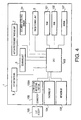
- Fig. 4 is a block diagram showing a configuration of a control system of the MFP 1.
- the MFP 1 includes a network interface (network I/F) 108 through which the MFP 1 is connected with a network (not shown) such as a LAN, a facsimile interface (facsimile I/F) 104 through which the MFP 1 is connected with a telephone line, a connector 106 (see Fig.
- a USB memory 105 configured such that a USB memory 105 is attached thereto or detached therefrom, a ROM 101 configured to store thereon processing programs for controlling various operations of the MFP 1, a RAM 102 configured to temporarily store thereon results of processes, a CPU 103 configured to execute the processing programs stored on the ROM 101, and a non-volatile memory (NVRAM) 107 configured to store thereon data required to be saved even after the MFP 1 is powered off.
- the connector 106 is provided with a connection detecting portion 106A configured to detect whether the USB memory 105 is connected to the connector 106.
- the CPU 103 is connected with the aforementioned scanning unit 5, image forming unit 6, automatic document feeding unit 7, operation panel 9, and document detecting sensor 24.
- FIG. 5 is a flowchart showing the FAX receiving process.
- the CPU 103 begins to execute the FAX receiving process based upon the program stored on the ROM 101.
- initializing operations are performed, which includes warming-up of the photoconductive drums 61.
- a subsequent step S2 it is determined through the facsimile interface 104 whether facsimile data is received.
- the facsimile data is not received (S2: No)
- the CPU 103 waits in a standby state in S2 until facsimile data is received.
- facsimile data is received (S2: Yes)
- the present process goes to S3.
- the present process goes to S3, in which a known FAX receiving operation is launched to receive the facsimile data in accordance with a predetermined protocol.
- the CPU 103 waits in a standby state until the facsimile data is completely received (S4: No). It is noted that the received facsimile data is once stored in a predetermined area of the NVRAM 107.
- the present process goes to S6, in which a size of sheet P is selected. In S6, the size of a sheet P placed in each of the sheet feed cassettes 2 is sequentially referred to. Then, when an intended size of sheet P (A4, legal size, or letter size) suitable for the FAX receiving process placed in a sheet feed cassette 2 is found, the sheet P as placed in the sheet feed cassette 2 is selected.
- an image corresponding to the received facsimile data (hereinafter referred to as received image data) is developed to print image data, namely, bitmap data in conformity to the sheet P selected in S6.
- received image data an image corresponding to the received facsimile data
- dot-on pixels of the print image data are counted. It is noted that, when the image data is printed on the sheet P, the toner T is transferred onto points on the sheet P that correspond to the dot-on pixels of the print image data.
- a dot-on ratio D is determined based upon the count of dot-on pixels. Specifically, in S9, a ratio of an area consisting of the dot-on pixels to a whole area on the sheet P is determined as the dot-on ratio D.
- the dot-on ratio D obtained in S9 is equal to or more than 25 %.
- the present embodiment is described under an assumption that a recycling manufacture provides a criterion that a printed sheet with a dot-on ratio D less than 25 % in monochrome printing is recyclable. Therefore, in the case of the dot-on ratio D ⁇ 25 %, even though the print image data is printed without any modification added thereto, the printed sheet P is recyclable.
- the dot-on ratio D ⁇ 25 % S10: No
- the present process goes to S11, in which the print image data is printed on the sheet P. Thereafter, the present process goes back to the aforementioned step S2. It is noted that, when a different criterion of the dot-on ratio D for a recyclable printed sheet is provided, the above value 25% is changed.
- the present process goes to S12, in which a reduction ratio R is determined to attain a dot-on ratio less than 25 %.
- a subsequent step S13 it is determined whether the reduction ratio R is less than 80 %.
- the received image data is re-developed to print image data (bitmap data) at the reduction ratio R in S14. Thereafter, the present process goes to S11, in which the print image data developed in S14 is printed on the sheet P. After that, the present process goes back to the aforementioned step S2.
- a method to reduce an area of each pixel is more desired than a method to thin pixels.
- exact information can be acquired from the reduced image.
- a resolution of facsimile data transmitted and received via a telephone line is generally 200 dpi (in the case of G3) while a resolution of the image forming unit 6 is generally 600 dpi (in the case of G3).
- the method to reduce an area of each pixel is more desired, and ensures the aforementioned effect that exact information can be acquired from the reduced image.
- the value (80 % in the first embodiment) to be compared with the reduction ratio in S 13 is desired to be changed.
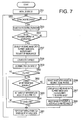
- Fig. 7 is a flowchart showing a FAX receiving process to be executed by the CPU 103 based upon a program stored on the ROM 101 in a second embodiment.
- the process is also launched based upon a program stored on the ROM 101 when the MFP 1 is powered ON.
- steps of S51 to S54 of the process operations similar to the steps of S1 to S4 are executed.
- the MFP 1 is initialized (S51), and then the CPU 103 waits in a standby state for facsimile data to be received (S52: No).
- facsimile data is received (S52: Yes)
- a FAX receiving operation is launched (S53), and the CPU 103 waits in a standby state until the facsimile data is completely received (S54).
- the received image data is developed to print image data (bitmap data) receiving operation in conformity to the minimum size of sheet P among two or more sizes of sheets P placed in the sheet feed cassettes 2, respectively.
- steps of S58 to S61 in the same manner as the aforementioned steps of S8 to S11, dot-on pixels of the print image data are counted (S58), and a dot-on ratio D is determined based upon the count of the dot-on pixels (S59).
- the dot-on ratio D is less than 25% (S60: No)
- the print image data developed in S57 is printed on the sheet P (S61)
- the present process goes to S52.
- the print image data includes a plurality of pages of data
- a dot-on ratio D is determined for each page, and the maximum dot-on ratio D is applied.
- sheets P of a single size are used over the plurality of pages.
- the present process goes to S62, in which it is determined whether a different size of sheet P is available.
- the sheet PA to discriminate it from the firstly selected sheet P
- the sheet PA is selected in S63.
- the present process goes to S64, in which it is determined whether D x (SA/S) ⁇ 25 % based upon an area SA of the newly selected sheet PA, an area S of the sheet P selected in S57, and the dot-on ratio D obtained in S59.
- a left part represents a dot-on ratio when the print image data is printed on the sheet PA.
- S64 it is determined whether the dot-on ratio as the left part in the inequality is less than 25 %.
- the present process goes to S66, in which the minimum size of sheet P is selected.
- the received image data is developed to print image data (bitmap data) in conformity to the selected sheet P.
- an image representing an unrecyclable printed sheet is inserted in the print image data.
- the print image data developed in S67 is printed along with the image representing an unrecyclable printed sheet added thereto, and then the present process goes to the aforementioned step S52.
- the print image data is printed on the sheet P of the minimum size (the letter size in the second embodiment) along with the image M representing an unrecyclable printed sheet. Therefore, the sheet P with the image M added thereon can be discriminated from recyclable sheets when the recyclable sheets are delivered to the recycling manufacture.
- a method to select a sheet P a method to select a sheet P by determining a sheet area required for a dot-on ratio D ⁇ 25 % based upon the number of the dot-on pixels can be applied.
- a method in which the dot-on ratio D is sequentially determined for each size of sheet P (S62 to S64) is easier.
- Fig. 9 is a flowchart showing a FAX receiving process to be executed by the CPU 103 based upon a program stored on the ROM 101 in a third embodiment.
- the process is also started based upon a program stored on the ROM 101 when the MFP 1 is powered ON.
- the MFP I is initialized in the same manner as S1.
- S81 it is determined via the connection detecting portion 106A whether the USB memory 105 is newly connected to the connector 106.
- S82 it is determined in S82 whether facsimile data is received.
- S82 the present process goes to S81.
- the CPU 103 waits in a standby state until the USB memory 105 is newly connected to the connector 106 or facsimile data is received in a loop of S81 and S82.
- the present process goes to S92, in which the received facsimile data is stored in a TIFF file format on the NVRAM 107 in a readable manner.
- S93 information on a sending source of the facsimile data is stored in the TIFF file format on the NVRAM 107 in a readable manner.
- the present process goes back to S81.
- TXT information respective piece of identification information
- the identification information of the sending source is used as the information on the sending source.
- the information on the sending source stored in S93 is stored in a predetermined area of the NVRAM 107 in association with the received facsimile data stored in S92.
- the received facsimile data is not printed and stored as a TIFF file in a readable manner on the NVRAM 107 (S92). Therefore, in the third embodiment as well, it is possible to prevent the printed sheet P from being unrecyclable.
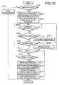
- Fig. 10 is a flowchart showing a detailed substitutional received data reading process. As illustrated in Fig. 10 , in the process, firstly in S102, it is determined whether there is any data stored in the aforementioned predetermined area of the NVRAM 107. When there is data stored in the aforementioned predetermined area of the NVRAM 107 (S102: Yes), the present process goes to S103.
- a list of information on sending sources corresponding to stored data is created.
- the created list is displayed as a user selection list on the LCD 9A. For instance, when "SuzukiTaro" is stored at the top of items of the information on the sending sources, an indication as exemplified in Fig. 11A is displayed on the LCD 9A.
- the CPU 103 waits in a standby state until the operation panel 9 is operated (S105: No).
- the operation panel 9 is operated (S105: Yes)
- the present process goes to S106, in which it is determined whether the above key operation is for selection on the list.
- the above key operation is for selection on the list (namely, a SET key is operated) (S106: Yes)
- S107 a mark "*" is attached to the above indication on the LCD 9A as a mark representing a selected item.
- the present process goes to the aforementioned step S105, in which the CPU 103 waits until a next key operation is made.
- an indication representing "under writing data” as illustrated in Fig. 11G is displayed on the LCD 9A.
- stored data corresponding to the selected item is written into the USB memory 105.
- the stored data and the information on the sending source that correspond to the selected item are deleted from the aforementioned predetermined area of the NVRAM 107.
- the indication representing "under writing data” is cleared, and thereafter the present process goes to the aforementioned step S81 (see Fig. 9 ).
- the data written in the USB memory 105 in this manner can be processed in a required way, for example, the data may be read as image data to be displayed on a personal computer (not shown) or printed with settings thereof such as the reduction ratio being modified.
- the present invention may be applied to image forming devices other than a multifunction peripheral and a facsimile machine. It is noted that, in a device configured to print facsimile data received via a public communication line as the aforementioned embodiments, since data is transmitted without relation to a user's intention, the effect that a printed sheet P is prevented from being unrecyclable is further remarkable.
- the aforementioned embodiments have been described under an assumption of single-side printing.
- the present invention may be applied to double-side printing as well by using an appropriate method to determine a printing ratio (dot-on ratio D). For instance, when one of surfaces of a sheet is printed, the printing ratio may be determined by dividing a printed area on the printed surface by an area of a single surface of the sheet.
Landscapes
- Engineering & Computer Science (AREA)
- Multimedia (AREA)
- Signal Processing (AREA)
- General Engineering & Computer Science (AREA)
- Computer Security & Cryptography (AREA)
- Microelectronics & Electronic Packaging (AREA)
- Physics & Mathematics (AREA)
- General Physics & Mathematics (AREA)
- Control Or Security For Electrophotography (AREA)
- Facsimiles In General (AREA)
- Record Information Processing For Printing (AREA)
- Accessory Devices And Overall Control Thereof (AREA)
Abstract
Description
- This application claims priority from Japanese Patent Application No.
2007-247229 filed on September 25, 2007 - The following description relates to one or more printing techniques to print an image corresponding to inputted image data on a sheet, particularly to one or more printing techniques to perform printing such that a printed sheet is recyclable.
- Recently, sheet recycling has been emphasized more and more while global environmental issues have been exacerbated year by year. When a printed sheet is recycled, the printed sheet is required to be sorted in accordance with a recycling classification thereof previously determined based upon a printing ratio as a ratio of printed areas to a whole area on the printed sheet. Thus, a printing device has been proposed, which is configured to, when printing a desired image on a sheet, determine a recycling classification of the printed sheet based upon a printing ratio of the image and a sort of the sheet, and to print information on the recycling classification as determined together with the image (for example, see Japanese Provisional Publication No.
2004-302752 - However, the aforementioned printing device cannot take automatic print control to sort each printed sheet into an intended recycling classification. Therefore, when a user wishes to sort each printed sheet into an intended recycling classification, the user has to modify inputted image data as needed. However, image data such as facsimile data may be inputted into the printing device without relation to a user's intension. In such a case, a printed sheet might be unrecyclable.
- Aspects of the present invention are advantageous to provide one or more improved printing devices that make it possible to prevent a printed sheet from being unrecyclable.
- According to aspects of the present invention, a printing device is provided, which includes a receiving means configured to receive image data, a printing means configured to transfer printing agent onto a sheet so as to form an image according to the image data received by the receiving means, a printing ratio determining means configured to determine, based upon the image data, a printing ratio that is a ratio of an area to be filled with the printing agent on the sheet to a whole area of the sheet, a first determining means configured to determine whether the printing ratio determined by the printing ratio determining means is equal to or more than a first predetermined value that is a printing ratio at less than which the sheet is classified into a recyclable sheet when the printing agent is transferred onto the sheet, and a control means configured to control the printing means to transfer the printing agent onto the sheet depending on the determination made by the first determining means.
- In some aspects, the printing ratio determining means determines a printing ratio as a ratio of an area to be filled with the printing agent on the sheet to the whole area of the sheet. Then, the first determining means determines whether the printing ratio determined is equal to or more than the first predetermined value as an upper limit of a printing ratio for a recyclable sheet. Then, the control means controls the printing means to transfer the printing agent onto the sheet depending on the determination made by the first determining means. Thus, since the control means controls a printing operation based upon the determination on whether the printing ratio determined is equal to or more than the upper limit of a printing ratio for a recyclable sheet, it is possible to prevent the printed sheet from being unrecyclable.
- According to aspects of the present invention, further provided is a method to transfer printing agent onto a sheet and form an image according to image data on the sheet. The method includes a printing ratio determining step of determining, based upon the image data, a printing ratio that is a ratio of an area to be filled with the printing agent on the sheet to a whole area of the sheet, a first determining step of determining whether the printing ratio determined in the printing ratio determining step is equal to or more than a first predetermined value that is a printing ratio at less than which the sheet is classified into a recyclable sheet when the printing agent is transferred onto the sheet, and a transferring step of transferring the printing agent onto the sheet depending on the determination made in the first determining step.
- The method adopted as above can provide the same effect as the aforementioned printing device.
-
-
Fig. 1 is an external view schematically showing a configuration of a multifunction peripheral (MFP) in embodiments according to one or more aspects of the present invention. -
Fig. 2 is a cross-sectional view schematically showing a configuration of the MFP including a main body cover and a scanning unit in the embodiments according to one or more aspects of the present invention. -
Fig. 3 is a schematic diagram showing a configuration of an image forming unit of the MFP in the embodiments according to one or more aspects of the present invention. -
Fig. 4 is a block diagram schematically showing a control system of the MFP in the embodiments according to one or more aspects of the present invention. -
Fig. 5 is a flowchart showing a FAX receiving process to be controlled by the control system in a first embodiment according to one or more aspects of the present invention. -
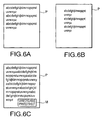
Figs. 6A to 6C are schematic diagrams for describing an effect of the FAX receiving process in the first embodiment according to one or more aspects of the present invention. -
Fig. 7 is a flowchart showing a FAX receiving process in a second embodiment according to one or more aspects of the present invention. -
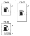
Figs. 8A to 8C are schematic diagrams for describing an effect of the FAX receiving process in the second embodiment according to one or more aspects of the present invention. -
Fig. 9 is a flowchart showing a FAX receiving process in a third embodiment according to one or more aspects of the present invention. -
Fig. 10 is a flowchart showing a substitutional received data reading process in the FAX receiving process in the third embodiment according to one or more aspects of the present invention. -
Figs. 11A to 11H are schematic diagrams showing indications displayed on a liquid crystal display in the substitutional received data reading process in the third embodiment according to one or more aspects of the present invention. - It is noted that various connections are set forth between elements in the following description. It is noted that these connections in general and, unless specified otherwise, may be direct or indirect and that this specification is not intended to be limiting in this respect. Aspects of the invention may be implemented in computer software as programs storable on computer-readable media including but not limited to RAMs, ROMs, flash memory, EEPROMs, CD-media, DVD-media, temporary storage, hard disk drives, floppy drives, permanent storage, and the like.
- Hereinafter, embodiments according to aspects of the present invention will be described with reference to the accompany drawings.
-
Fig. 1 is an external view schematically showing a configuration of a multifunction peripheral (MFP) 1 as an image forming device according to aspects of the present invention. As shown inFig. 1 , the MFP 1 is provided with a plurality ofsheet feed trays 2 configured to feed a sheet P (seeFig. 3 ) on which an image is formed, amain body 3 configured to form an image on the sheet P fed from one of thesheet feed trays 2, and amain body cover 4 supported by themain body 3 in an openable and closable manner so as to completely cover an upper face of themain body 3. - The
main body 3 includes therein a scanning unit 5 (seeFig. 2 ) configured to scan an image formed on an original document G (seeFig. 2 ) and an image forming unit 6 (seeFig. 3 ) configured to form an image on the sheet P fed from one of thesheet feed trays 2. Thescanning unit 5 is a known one that scans an image formed on the original document G which is placed on ascanning surface 3A (seeFig. 2 ) provided on the upper face of themain body 3 or carried by an automaticdocument feeding unit 7 with a configuration described below. Additionally, theimage forming unit 6 is configured as a known printer engine that forms an image in an electrophotographic method with yellow toner, magenta toner, cyan toner, and black toner. Theimage forming unit 6 forms an image on the sheet P on a sheet-by-sheet basis and discharges the sheet P with the image formed thereon from adischarge slot 8. Further, anoperation panel 9 is provided on the upper face of themain body 3, which includes a liquid crystal display (LCD) 9A and various kinds of buttons. -
Fig. 2 is a cross-sectional view schematically showing configurations of themain body cover 4 and thescanning unit 5. As illustrated inFig. 2 , themain body cover 4 includes aloading portion 21 configured to be loaded with the original document G which is about to be scanned by thescanning unit 5, a stacker portion 31 on which the original document G scanned by thescanning unit 5 is stacked, and acarrying unit 25 that carries the original document G from theloading portion 21 to the stacker portion 31 via thescanning surface 3A (namely, which carries the original document G to the stacker portion 31 after letting thescanning unit 5 held in a scanning position R in automatic document feeding scan the original document G). Thus, the automatic document feeding unit 7 (so-called automatic document feeder ADF) is configured with theloading portion 21, stacker portion 31, and carryingunit 25. - In addition, as illustrated in
Fig. 2 , thescanning unit 5 is provided with alight source 53 configured to emit light toward the original document G, anoptical element group 52 configured to collect light reflected by the original document G, and animage sensor 51 for scanning an image (including colors) formed on the original document G. Namely, thescanning unit 5 is configured to scan the image on the original document G by emitting light from thelight source 53, collecting the light reflected by the original document G with theoptical element group 52, and detecting, with theimage sensor 51, the reflected light collected. - Further, the
scanning unit 5 is configured to scan the original document G in such a position as to face the scanning position R and movable along a longitudinal direction of the main body 3 (right-to-left direction) parallel to thescanning surface 3A with a scanning unit driving mechanism (not shown). - Specifically, when scanning the original document G with the automatic
document feeding unit 7, thescanning unit 5 is held in the position facing the scanning position R, and completely scans the original document G fed by the automaticdocument feeding unit 7. Further, when scanning the original document G placed so as to cover thescanning surface 3A (when being used as a so-called flatbed scanner), thescanning unit 5, while being shifted by the scanning unit driving mechanism, completely scans the original document G placed on thescanning surface 3A. - On the
loading portion 21, adocument detecting sensor 24 is disposed, which detects whether the original document G is placed on theloading portion 21. Themain body 3 includes a scanning surface detecting sensor (not shown) configured to detect whether the original document G is placed on thescanning surface 3A. Thedocument detecting sensor 24 is an optical sensor configured with alight emitting portion 24A and alight receiving portion 24B. Thelight emitting portion 24A and thelight receiving portion 24B are disposed to face each other such that the original document G placed on theloading portion 21 blocks light emitted by thelight emitting portion 24A toward thelight receiving portion 24B. - Therefore, in the
document detecting sensor 24, when the original document G does not exist on theloading portion 21, the light emitted by thelight emitting portion 24A is detected by thelight receiving portion 24B. Thus, thelight receiving portion 24B issues a light receiving signal of a high signal level. Meanwhile, when the original document G exists on theloading portion 21, the light is blocked by the original document G and is not detected by thelight receiving portion 24B. Thus, thelight receiving portion 24B issues a light receiving signal of a low signal level. - The
image forming unit 6 is configured as shown inFig. 3 . Specifically, as illustrated inFig. 3 , theimage forming unit 6 includes aphotoconductive drum 61 configured to hold on a surface thereof an electrostatic latent image formed through exposure of laser light L and ascanner unit 62 configured to expose the surface of thephotoconductive drum 61 with the laser light L. Additionally, thescanner unit 62 is provided with a laser diode (not shown) and a polygon mirror (not shown) and also configured in a known fashion to scan and expose thephotoconductive drum 61 in a direction along a rotational axis of thephotoconductive drum 61. - Further, the
photoconductive drum 61 is configured to rotate in a direction indicated by an arrow inFig. 3 . Around thephotoconductive drum 61, there are disposed a scorotron-type charger 63 configured to charge the surface of thephotoconductive drum 61 evenly, a developingroller 65 configured to make toner T, which is developer stored in atoner cartridge 64, adhere onto the surface of thephotoconductive drum 61 and develop the electrostatic latent image, and atransfer roller 66 configured to carry the sheet P pinched between itself and thephotoconductive drum 61 and to transfer the toner T, which the developingroller 65 has made adhere onto the surface of thephotoconductive drum 61, onto the sheet P. Further, the sheet P on which the image is formed through the transfer of the toner T is conveyed to between aheating roller 67 and apressing roller 68, and the toner T transferred is fixed onto the sheet P. - Additionally, it is not shown in
Fig. 3 , yet theimage forming unit 6 is a tandem type laser printer provided with respectivephotoconductive drums 61 for four colors cyan (C), magenta (M), yellow (Y), and black (K). After toner images of the four colors are formed, the fixing operation is performed with theheating roller 67 and thepressing roller 68. - Further, the
image forming unit 6 is provided with asheet feed roller 2A for eachsheet feed cassette 2. The sheet P fed by driving any one of thesheet feed rollers 2A is supplied to between a correspondingphotoconductive drum 61 and acorresponding transfer roller 66. Three or moresheet feed cassettes 2 may be provided. In this case as well, it is possible to drive an intended one of the respectivesheet feed rollers 2A of thesheet feed cassettes 2. -
Fig. 4 is a block diagram showing a configuration of a control system of the MFP 1. As illustrated inFig. 4 , The MFP 1 includes a network interface (network I/F) 108 through which the MFP 1 is connected with a network (not shown) such as a LAN, a facsimile interface (facsimile I/F) 104 through which the MFP 1 is connected with a telephone line, a connector 106 (seeFig. 1 ) configured such that aUSB memory 105 is attached thereto or detached therefrom, aROM 101 configured to store thereon processing programs for controlling various operations of the MFP 1, aRAM 102 configured to temporarily store thereon results of processes, aCPU 103 configured to execute the processing programs stored on theROM 101, and a non-volatile memory (NVRAM) 107 configured to store thereon data required to be saved even after the MFP 1 is powered off. Additionally, theconnector 106 is provided with aconnection detecting portion 106A configured to detect whether theUSB memory 105 is connected to theconnector 106. Further, theCPU 103 is connected with theaforementioned scanning unit 5,image forming unit 6, automaticdocument feeding unit 7,operation panel 9, and document detectingsensor 24. - Subsequently, a FAX receiving process to be executed by the
CPU 103 based upon a program stored on theROM 101 in a first embodiment will be described.Fig. 5 is a flowchart showing the FAX receiving process. When the MFP 1 is powered ON, theCPU 103 begins to execute the FAX receiving process based upon the program stored on theROM 101. - As shown in
Fig. 5 , firstly in S1 of the present process, initializing operations are performed, which includes warming-up of the photoconductive drums 61. In a subsequent step S2, it is determined through thefacsimile interface 104 whether facsimile data is received. When the facsimile data is not received (S2: No), theCPU 103 waits in a standby state in S2 until facsimile data is received. Then, when facsimile data is received (S2: Yes), the present process goes to S3. - When an instruction to transmit by FAX the document G set on the automatic
document feeding unit 7 is issued via theoperation panel 9 in the standby state of theCPU 103 in S2, a known FAX transmission process is performed, and the present process goes back to S2. In the same manner, when image data is received from a personal computer via thenetwork interface 108 in the standby state of theCPU 103 in S2, a printing process is performed, and the present process goes back to S2. Further, when a copy instruction is issued via theoperation panel 9 in the standby state of theCPU 103 in S2, a copy process of copying the document G is performed, and the present process goes back to S2. - When facsimile data is received (S2: Yes), the present process goes to S3, in which a known FAX receiving operation is launched to receive the facsimile data in accordance with a predetermined protocol. In a subsequent step S4, the
CPU 103 waits in a standby state until the facsimile data is completely received (S4: No). It is noted that the received facsimile data is once stored in a predetermined area of theNVRAM 107. When the facsimile data is completely received (S4: Yes), the present process goes to S6, in which a size of sheet P is selected. In S6, the size of a sheet P placed in each of thesheet feed cassettes 2 is sequentially referred to. Then, when an intended size of sheet P (A4, legal size, or letter size) suitable for the FAX receiving process placed in asheet feed cassette 2 is found, the sheet P as placed in thesheet feed cassette 2 is selected. - In a subsequent step S7, an image corresponding to the received facsimile data (hereinafter referred to as received image data) is developed to print image data, namely, bitmap data in conformity to the sheet P selected in S6. In S8, dot-on pixels of the print image data are counted. It is noted that, when the image data is printed on the sheet P, the toner T is transferred onto points on the sheet P that correspond to the dot-on pixels of the print image data. Then, in S9, a dot-on ratio D is determined based upon the count of dot-on pixels. Specifically, in S9, a ratio of an area consisting of the dot-on pixels to a whole area on the sheet P is determined as the dot-on ratio D.
- Thereafter, in S10, it is determined whether the dot-on ratio D obtained in S9 is equal to or more than 25 %. The present embodiment is described under an assumption that a recycling manufacture provides a criterion that a printed sheet with a dot-on ratio D less than 25 % in monochrome printing is recyclable. Therefore, in the case of the dot-on ratio D < 25 %, even though the print image data is printed without any modification added thereto, the printed sheet P is recyclable. When the dot-on ratio D < 25 % (S10: No), the present process goes to S11, in which the print image data is printed on the sheet P. Thereafter, the present process goes back to the aforementioned step S2. It is noted that, when a different criterion of the dot-on ratio D for a recyclable printed sheet is provided, the
above value 25% is changed. - Meanwhile, when it is determined that the dot-on ratio is equal to or more than 25 % (S10: Yes), the present process goes to S12, in which a reduction ratio R is determined to attain a dot-on ratio less than 25 %. Specifically, the reduction ratio R to attain a dot-on ratio of 24 % is determined by substituting the dot-on ratio D obtained in S9 into an equation "R [%] = (24/D) x 100."
- In a subsequent step S13, it is determined whether the reduction ratio R is less than 80 %. When the reduction ratio R is equal to or more than 80 % (S13: No), the received image data is re-developed to print image data (bitmap data) at the reduction ratio R in S14. Thereafter, the present process goes to S11, in which the print image data developed in S14 is printed on the sheet P. After that, the present process goes back to the aforementioned step S2.
- When it is determined that the reduction ratio R is less than 80 % (S13: Yes), an image representing that the printed sheet P is unrecyclable is inserted into the print image data in S15. Then, the present process goes to S11, in which the print image data developed with a normal magnification in S7 is printed on the sheet P together with the image representing an unrecyclable printed sheet. Thereafter, the present process goes back to the aforementioned step S2.
- Thus, for instance, even though facsimile data is received that would cause an unrecyclable printed sheet with a dot-on ratio D ≥ 25 % when the facsimile data is printed without any modification added thereto (S10: Yes), it is possible to attain a dot-on ratio R < 25 % through reduction printing as shown in
Fig. 6B (S12 and S14) and therefore to recycle the printed sheet P. Hence, it is possible to prevent the printed sheet P from being unrecyclable. - In addition, as exemplified in
Fig. 6C , when facsimile data is received that needs a reduction ratio R less than 80 % in order to attain a dot-on ratio D < 25 %, the facsimile data is printed, without being reduced, with an image M representing an unrecyclable printed sheet added thereto. Therefore, it is possible to prevent the received image data from being excessively reduced and to acquire exact information from the printed image. Further, in this case, since the image M representing an unrecyclable printed sheet is inserted, a sheet P with the image M added thereto can be discriminated as an unrecyclable sheet from recyclable sheets before the recyclable sheets are delivered to the recycling manufacture. - As a method to re-develop the received image data to the print image data at the reduction ratio R in S14, a method to reduce an area of each pixel is more desired than a method to thin pixels. Thereby, exact information can be acquired from the reduced image. In particular, a resolution of facsimile data transmitted and received via a telephone line is generally 200 dpi (in the case of G3) while a resolution of the
image forming unit 6 is generally 600 dpi (in the case of G3). Hence, the method to reduce an area of each pixel is more desired, and ensures the aforementioned effect that exact information can be acquired from the reduced image. Further, depending on the resolution of theimage forming unit 6, the value (80 % in the first embodiment) to be compared with the reduction ratio inS 13 is desired to be changed. -
Fig. 7 is a flowchart showing a FAX receiving process to be executed by theCPU 103 based upon a program stored on theROM 101 in a second embodiment. - The process is also launched based upon a program stored on the
ROM 101 when the MFP 1 is powered ON. In steps of S51 to S54 of the process, operations similar to the steps of S1 to S4 are executed. Specifically, the MFP 1 is initialized (S51), and then theCPU 103 waits in a standby state for facsimile data to be received (S52: No). When facsimile data is received (S52: Yes), a FAX receiving operation is launched (S53), and theCPU 103 waits in a standby state until the facsimile data is completely received (S54). When the facsimile data is completely received (S54: Yes), in a subsequent step S57, the received image data is developed to print image data (bitmap data) receiving operation in conformity to the minimum size of sheet P among two or more sizes of sheets P placed in thesheet feed cassettes 2, respectively. - In steps of S58 to S61, in the same manner as the aforementioned steps of S8 to S11, dot-on pixels of the print image data are counted (S58), and a dot-on ratio D is determined based upon the count of the dot-on pixels (S59). When the dot-on ratio D is less than 25% (S60: No), the print image data developed in S57 is printed on the sheet P (S61), the present process goes to S52. In this case, when the print image data includes a plurality of pages of data, a dot-on ratio D is determined for each page, and the maximum dot-on ratio D is applied. Thereby, sheets P of a single size are used over the plurality of pages.
- Meanwhile, when the dot-on ratio D is equal to or more than 25 % (S60: Yes), the present process goes to S62, in which it is determined whether a different size of sheet P is available. When a different size of sheet P (hereinafter referred to as the sheet PA to discriminate it from the firstly selected sheet P) is available (S62: Yes), the sheet PA is selected in S63. Thereafter, the present process goes to S64, in which it is determined whether D x (SA/S) < 25 % based upon an area SA of the newly selected sheet PA, an area S of the sheet P selected in S57, and the dot-on ratio D obtained in S59. In the above inequality, a left part represents a dot-on ratio when the print image data is printed on the sheet PA. In other words, in S64, it is determined whether the dot-on ratio as the left part in the inequality is less than 25 %.
- When D x (SA/S) < 25 % (S64: Yes), the present process goes to S61, in which the print data image developed in S57 is printed on the sheet PA. Thereafter, the present process goes back to S52. Meanwhile, when D x (SA/S) ≥ 25 % (S64: No), the present process goes to the aforementioned step S62, in which it is further determined whether a different size of sheet P is available.
- When it is determined that a different size of sheet P is not available (S62: No), the present process goes to S66, in which the minimum size of sheet P is selected. In a subsequent step S67, the received image data is developed to print image data (bitmap data) in conformity to the selected sheet P. In S68, an image representing an unrecyclable printed sheet is inserted in the print image data. After that, in S60, the print image data developed in S67 is printed along with the image representing an unrecyclable printed sheet added thereto, and then the present process goes to the aforementioned step S52.
- Therefore, for example, as exemplified in
Fig. 8A , even though facsimile data is received that would cause an unrecyclable printed sheet with a dot-on ratio D ≥ 25 % when it is printed on a sheet P of a letter size (S60: Yes), it is possible to attain a dot-on ratio D less than 25 % by printing the facsimile data on a sheet P of a legal size (S64: Yes). Namely, the printed sheet P is classified as a recyclable sheet. Thus, it is possible to prevent the printed sheet P from being unrecyclable. - Further, as exemplified in
Fig. 8C , when the dot-on ratio is equal to or more than 25 % even though any size of sheet P is selected, the print image data is printed on the sheet P of the minimum size (the letter size in the second embodiment) along with the image M representing an unrecyclable printed sheet. Therefore, the sheet P with the image M added thereon can be discriminated from recyclable sheets when the recyclable sheets are delivered to the recycling manufacture. It is noted that, as a method to select a sheet P, a method to select a sheet P by determining a sheet area required for a dot-on ratio D < 25 % based upon the number of the dot-on pixels can be applied. However, a method in which the dot-on ratio D is sequentially determined for each size of sheet P (S62 to S64) is easier. -
Fig. 9 is a flowchart showing a FAX receiving process to be executed by theCPU 103 based upon a program stored on theROM 101 in a third embodiment. - The process is also started based upon a program stored on the
ROM 101 when the MFP 1 is powered ON. Firstly in S80, the MFP I is initialized in the same manner as S1. In S81, it is determined via theconnection detecting portion 106A whether theUSB memory 105 is newly connected to theconnector 106. When theUSB memory 105 is not connected to the connector 106 (S81: No), it is determined in S82 whether facsimile data is received. When any facsimile data is not received (S82: No), the present process goes to S81. Thus, theCPU 103 waits in a standby state until theUSB memory 105 is newly connected to theconnector 106 or facsimile data is received in a loop of S81 and S82. - When facsimile data is received (S82: Yes), operations similar to the aforementioned S3 to S10. Specifically, a FAX receiving operation is started (S83), and the
CPU 103 waits in a standby state until the facsimile data is completely received (S84: No). Thereafter, a sheet P is selected (S86), and the received image data is developed to print image data (bitmap data) in conformity to the sheet P (S87). Subsequently, dot-on pixels of the print image data are counted (S88), and a dot-on ratio D is determined based upon the count of the dot-on pixels (S89). Then it is determined whether the dot-on ratio is equal to or more than 25 % (S90). When the dot-on ratio is less than 25 % (S90: No), the present process goes to S91, in which the print image data is printed on the sheet P in the same manner as the aforementioned step S11. Thereafter, the present process goes back to S81. - Meanwhile, when the dot-on ratio D is equal to or more than 25 % (S90: Yes), the present process goes to S92, in which the received facsimile data is stored in a TIFF file format on the
NVRAM 107 in a readable manner. In S93, information on a sending source of the facsimile data is stored in the TIFF file format on theNVRAM 107 in a readable manner. Thereafter, the present process goes back to S81. It is noted that, in facsimile data communication, in an initial stage of communication negotiation, respective piece of identification information (TEXT information) of a sending source and a receiving device are exchanged. In S93, the identification information of the sending source is used as the information on the sending source. The information on the sending source stored in S93 is stored in a predetermined area of theNVRAM 107 in association with the received facsimile data stored in S92. - Thus, in the present process, when the dot-on ratio D is equal to or more than 25 % (S90: Yes), the received facsimile data is not printed and stored as a TIFF file in a readable manner on the NVRAM 107 (S92). Therefore, in the third embodiment as well, it is possible to prevent the printed sheet P from being unrecyclable.
- Meanwhile, in the present process, when the
USB memory 105 is connected to theconnector 106 while theCPU 103 is waiting in the loop of S81 and S82 (S81: Yes), a substitutional received data reading process is executed in S100.Fig. 10 is a flowchart showing a detailed substitutional received data reading process. As illustrated inFig. 10 , in the process, firstly in S102, it is determined whether there is any data stored in the aforementioned predetermined area of theNVRAM 107. When there is data stored in the aforementioned predetermined area of the NVRAM 107 (S102: Yes), the present process goes to S103. - In S103, a list of information on sending sources corresponding to stored data is created. In a subsequent S104, the created list is displayed as a user selection list on the
LCD 9A. For instance, when "SuzukiTaro" is stored at the top of items of the information on the sending sources, an indication as exemplified inFig. 11A is displayed on theLCD 9A. - Back to
Fig. 10 , in S105, theCPU 103 waits in a standby state until theoperation panel 9 is operated (S105: No). When theoperation panel 9 is operated (S105: Yes), the present process goes to S106, in which it is determined whether the above key operation is for selection on the list. When the above key operation is for selection on the list (namely, a SET key is operated) (S106: Yes), in S107, a mark "*" is attached to the above indication on theLCD 9A as a mark representing a selected item. Then, the present process goes to the aforementioned step S105, in which theCPU 103 waits until a next key operation is made. - Meanwhile, when the above key operation is not for selection on the list (S 106: No), in S108, it is determined whether the above key operation is made to move a cursor (namely, an up/down key is operated). When the above key operation is made to move a cursor (S108: Yes), in S109, the item of the information on the sending sources displayed on the
LCD 9A is moved on the list. Thereafter, the present process goes to theaforementioned step S 105. - Therefore, when the up/down key is operated in the standby state in S105 (S108: Yes), as exemplified in
Fig. 11C or 11E , the item of the information on the sending sources displayed on theLCD 9A is changed in S109. Then, when the SET key is operated in any state shown inFig. 11A, 11C, or 11E (S 106: Yes), the mark "*" is attached onto a left side of the item of the information on the sending sources (S107), and the item with the mark "*" attached thereto is selected. - Meanwhile, when a key other than the aforementioned keys is operated in the standby state in S105 (S 108: No), it is determined in S111 whether the key operation is operation of a CANCEL key. When the key operation is operation of the CANCEL key (S111: Yes), the substitutional received data reading process is once terminated, and the present process goes to the aforementioned step S81 (see
Fig. 9 ). Meanwhile, when the above key operation is not operation of the CANCEL key (S111: No), it is determined in S112 whether the key operation is for fixing the selection (namely, a START key is operated). Thereafter, the present process goes to S113. - In S113, an indication representing "under writing data" as illustrated in
Fig. 11G is displayed on theLCD 9A. Then, in S114, stored data corresponding to the selected item is written into theUSB memory 105. In a subsequent step S 115, the stored data and the information on the sending source that correspond to the selected item are deleted from the aforementioned predetermined area of theNVRAM 107. In S116, the indication representing "under writing data" is cleared, and thereafter the present process goes to the aforementioned step S81 (seeFig. 9 ). Thus, in the third embodiment, when a plurality of received image data are stored in the predetermined area of theNVRAM 107, intended data is selected via a key operation on theoperation panel 9 and written into theUSB memory 105. The data written in theUSB memory 105 in this manner can be processed in a required way, for example, the data may be read as image data to be displayed on a personal computer (not shown) or printed with settings thereof such as the reduction ratio being modified. - Meanwhile, when it is determined that there is not any data stored in the aforementioned predetermined area of the NVRAM 107 (S102: No), the present process goes to S118, in which an indication representing no data received is displayed as illustrated in
Fig. 11H . Thereafter, the present process goes to the aforementioned step S81. - The aforementioned embodiments have been described with an example of a general facsimile machine configured to print an image corresponding to facsimile data transmitted via a telephone line as an example of a public communication line. However, the present invention may be applied to an IP facsimile machine.
- Further, the present invention may be applied to image forming devices other than a multifunction peripheral and a facsimile machine. It is noted that, in a device configured to print facsimile data received via a public communication line as the aforementioned embodiments, since data is transmitted without relation to a user's intention, the effect that a printed sheet P is prevented from being unrecyclable is further remarkable.
- Additionally, the aforementioned embodiments have been described under an assumption of single-side printing. However, the present invention may be applied to double-side printing as well by using an appropriate method to determine a printing ratio (dot-on ratio D). For instance, when one of surfaces of a sheet is printed, the printing ratio may be determined by dividing a printed area on the printed surface by an area of a single surface of the sheet.
- Hereinabove, the embodiments according to aspects of the present invention have been described. The present invention can be practiced by employing conventional materials, methodology and equipment. Accordingly, the details of such materials, equipment and methodology are not set forth herein in detail. In the previous descriptions, numerous specific details are set forth, such as specific materials, structures, chemicals, processes, etc., in order to provide a thorough understanding of the present invention. However, it should be recognized that the present invention can be practiced without reapportioning to the details specifically set forth. In other instances, well known processing structures have not been described in detail, in order not to unnecessarily obscure the present invention.
- Only exemplary embodiments of the present invention and but a few examples of its versatility are shown and described in the present disclosure. It is to be understood that the present invention is capable of use in various other combinations and environments and is capable of changes or modifications within the scope of the inventive concept as expressed herein.
Claims (19)
- A printing device, comprising:a receiving means configured to receive image data;a printing means configured to transfer printing agent onto a sheet so as to form an image according to the image data received by the receiving means;a printing ratio determining means configured to determine, based upon the image data, a printing ratio that is a ratio of an area to be filled with the printing agent on the sheet to a whole area of the sheet;a first determining means configured to determine whether the printing ratio determined by the printing ratio determining means is equal to or more than a first predetermined value that is a printing ratio at less than which the sheet is classified into a recyclable sheet when the printing agent is transferred onto the sheet; anda control means configured to control the printing means to transfer the printing agent onto the sheet depending on the determination made by the first determining means.
- The printing device according to claim 1
wherein the control means includes a reduction ratio determining means configured to determine a reduction ratio to attain a printing ratio less than the first predetermined value when the first determining means determines that the determined printing ratio is equal to or more than the first predetermined value, the reduction ratio being a ratio of an area of a reduced image of an original image according to the image data to an area of the original image, and
wherein the control means controls the printing means to print, on the sheet, the reduced image formed by reducing the original image at the reduction ratio determined by the reduction ratio determining means. - The printing device according to claim 2,
wherein the reduced image is formed by reducing an area of each pixel included in the original image. - The printing device according to claim 3,
wherein the receiving means includes a facsimile data receiving means configured to receive facsimile data as the image data received by the receiving means, via a public communication line,
wherein the printing means is capable of printing an image with a resolution higher than a resolution of the facsimile data received by the facsimile data receiving means. - The printing device according to any of claims 2 to 4,
wherein the control means further includes a second determining means configured to determine whether the reduction ratio determined by the reduction ratio determining means is less than a second predetermined value, and
wherein the control means controls the printing means to print the original image on the sheet without reducing the original image when the second determining means determines that the reduction ratio is less than the second predetermined value. - The printing device according to claim 4, further comprising an image inserting means configured to insert, into the received image data, an image representing that the selected sheet on which the original image is to be printed is unrecyclable when the second determining means determines that the reduction ratio is less than the second predetermined value.
- The printing device according to claim 1, further comprising:a sheet feeding means configured to selectively feed one of a plurality of sheets of respective different sizes as the sheet to be printed by the printing means; anda sheet selecting means configured to select, from the plurality of sheets, a sheet of a size that is classified into a recyclable sheet when the printing agent is transferred thereon based upon the image data, as a sheet to be fed by the sheet feeding means.
- The printing device according to claim 7,
wherein the printing ratio determining means determines a printing ratio for each of the plurality of sheets,
wherein the sheet selecting means includes a recyclability determining means configured to determine whether the printing ratio determined for each of the plurality of sheets by the printing ratio determining means is less than a predetermined value that is a printing ratio at less than which a sheet is classified into a recyclable sheet when an image is printed on the sheet, and
wherein the sheet selecting means selects a sheet of the plurality of sheets for which the printing ratio is determined by the recyclability determining means to be less than the predetermined value. - The printing device according to claim 8,
wherein, when the image data received by the receiving means includes images extending over a plurality of pages, the sheet selecting means selects a sheet based upon the highest one of printing ratios determined for the plurality of pages. - The printing device according to claim 8,
wherein, when there is no sheet for which the printing ratio is less than the predetermined value, the sheet selecting means selects a sheet of the smallest size which is large enough for the received image data to be printed therewithin. - The printing device according to claim 10, further comprising an image inserting means configured to insert, into the image data received by the receiving means, an image representing that the sheet of the smallest size selected by the sheet selecting means is unrecyclable when there is no sheet for which the printing ratio is less than the predetermined value.
- The printing device according to claim 1,
wherein the control means controls the printing means to print the image according to the image data on the sheet without reducing the image when the first determining means determines that the printing ratio is less than the first predetermined value. - The printing device according to claim 12, further comprising a storage means configured to store thereon the image data when the first determining means determines that the printing ratio is equal to or more than the predetermined value.
- The printing device according to claim 13, further comprising:a storage device connector configured to be connected with a storage device;a detecting means configured to detect whether the storage device is connected to the storage device connector;a data selecting means configured to accept an input to select data from image data stored on the storage means when the detecting means detects that the storage device is connected to the storage device connector; anda storing means configured to store the data selected through the data selecting means into the storage device connected to the storage device connector.
- The printing device according to any of claims 1, and 7 to 14,
wherein the receiving means includes a facsimile data receiving means configured to receive facsimile data as the image data received by the receiving data, via a public communication line. - A method to transfer printing agent onto a sheet and form an image according to image data on the sheet, comprising:a printing ratio determining step of determining, based upon the image data, a printing ratio that is a ratio of an area to be filled with the printing agent on the sheet to a whole area of the sheet;a first determining step of determining whether the printing ratio determined in the printing ratio determining step is equal to or more than a first predetermined value that is a printing ratio at less than which the sheet is classified into a recyclable sheet when the printing agent is transferred onto the sheet; anda transferring step of transferring the printing agent onto the sheet depending on the determination made in the first determining step.
- The method according to claim 16, further comprising:a reduction ratio determining step of determining a reduction ratio to attain a printing ratio less than the first predetermined value when it is determined in the first determining step that the determined printing ratio is equal to or more than the first predetermined value, the reduction ratio being a ratio of an area of a reduced image of an original image according to the image data to an area of the original image; anda reduced image forming step of forming the reduced image by reducing the original image at the reduction ratio determined in the reduction ratio determining step,wherein the transferring step includes a first printing step of printing, on the sheet, the reduced image formed in the reduced image forming step.
- The method according to claim 17,
wherein the reduced image forming step includes a step of reducing an area of each pixel included in the original image. - The method according to claim 17, further comprising a second determining step of determining whether the reduction ratio determined in the reduction ratio determining step is less than a second predetermined value,
wherein the transferring step includes a second printing step of printing the original image on the sheet without reducing the original image when it is determined in the second determining step that the reduction ratio is less than the second predetermined value.
Applications Claiming Priority (1)
| Application Number | Priority Date | Filing Date | Title |
|---|---|---|---|
| JP2007247229A JP4569615B2 (en) | 2007-09-25 | 2007-09-25 | Printing device |
Publications (3)
| Publication Number | Publication Date |
|---|---|
| EP2042933A2 true EP2042933A2 (en) | 2009-04-01 |
| EP2042933A3 EP2042933A3 (en) | 2010-04-28 |
| EP2042933B1 EP2042933B1 (en) | 2020-02-12 |
Family
ID=40040062
Family Applications (1)
| Application Number | Title | Priority Date | Filing Date |
|---|---|---|---|
| EP08015230.9A Not-in-force EP2042933B1 (en) | 2007-09-25 | 2008-08-28 | Printing device and method therefor |
Country Status (3)
| Country | Link |
|---|---|
| US (1) | US8184331B2 (en) |
| EP (1) | EP2042933B1 (en) |
| JP (1) | JP4569615B2 (en) |
Cited By (1)
| Publication number | Priority date | Publication date | Assignee | Title |
|---|---|---|---|---|
| EP2063323A2 (en) | 2007-11-21 | 2009-05-27 | Brother Kogyo Kabushiki Kaisha | Printing device, printing method and printing system |
Families Citing this family (2)
| Publication number | Priority date | Publication date | Assignee | Title |
|---|---|---|---|---|
| JP4433026B2 (en) * | 2007-09-21 | 2010-03-17 | ブラザー工業株式会社 | Paper sorting device |
| JP6939130B2 (en) * | 2017-06-22 | 2021-09-22 | セイコーエプソン株式会社 | Printing device and control method |
Citations (2)
| Publication number | Priority date | Publication date | Assignee | Title |
|---|---|---|---|---|
| JP2004302752A (en) | 2003-03-31 | 2004-10-28 | Brother Ind Ltd | Printing control device, printing device, and program |
| JP2007247229A (en) | 2006-03-15 | 2007-09-27 | Takayama Metal Industrial Co Ltd | Hanging tree |
Family Cites Families (83)
| Publication number | Priority date | Publication date | Assignee | Title |
|---|---|---|---|---|
| US3638640A (en) * | 1967-11-01 | 1972-02-01 | Robert F Shaw | Oximeter and method for in vivo determination of oxygen saturation in blood using three or more different wavelengths |
| US4936679A (en) * | 1985-11-12 | 1990-06-26 | Becton, Dickinson And Company | Optical fiber transducer driving and measuring circuit and method for using same |
| US5564417A (en) * | 1991-01-24 | 1996-10-15 | Non-Invasive Technology, Inc. | Pathlength corrected oximeter and the like |
| US4972331A (en) * | 1989-02-06 | 1990-11-20 | Nim, Inc. | Phase modulated spectrophotometry |
| US5873821A (en) * | 1992-05-18 | 1999-02-23 | Non-Invasive Technology, Inc. | Lateralization spectrophotometer |
| CA1331483C (en) * | 1988-11-02 | 1994-08-16 | Britton Chance | User-wearable hemoglobinometer for measuring the metabolic condition of a subject |
| US5122974A (en) * | 1989-02-06 | 1992-06-16 | Nim, Inc. | Phase modulated spectrophotometry |
| US5119815A (en) * | 1988-12-21 | 1992-06-09 | Nim, Incorporated | Apparatus for determining the concentration of a tissue pigment of known absorbance, in vivo, using the decay characteristics of scintered electromagnetic radiation |
| US6183414B1 (en) * | 1999-04-26 | 2001-02-06 | Michael S. Wysor | Technique for restoring plasticity to tissues of a male or female organ |
| US6708048B1 (en) * | 1989-02-06 | 2004-03-16 | Non-Invasive Technology, Inc. | Phase modulation spectrophotometric apparatus |
| US6681128B2 (en) * | 1990-10-06 | 2004-01-20 | Hema Metrics, Inc. | System for noninvasive hematocrit monitoring |
| US6246894B1 (en) * | 1993-02-01 | 2001-06-12 | In-Line Diagnostics Corporation | System and method for measuring blood urea nitrogen, blood osmolarity, plasma free hemoglobin and tissue water content |
| US6549795B1 (en) * | 1991-05-16 | 2003-04-15 | Non-Invasive Technology, Inc. | Spectrophotometer for tissue examination |
| ES2123535T3 (en) * | 1992-01-25 | 1999-01-16 | Alsthom Cge Alcatel | PROCEDURE TO FACILITATE THE MANAGEMENT OF TERMINAL DEVICES IN TELECOMMUNICATION FACILITIES. |
| US6785568B2 (en) * | 1992-05-18 | 2004-08-31 | Non-Invasive Technology Inc. | Transcranial examination of the brain |
| JP3506743B2 (en) | 1993-10-28 | 2004-03-15 | 株式会社リコー | Image output device |
| CA2155932A1 (en) * | 1993-12-14 | 1995-06-22 | Tadakazu Yamauchi | Medical measuring apparatus |
| US5645059A (en) * | 1993-12-17 | 1997-07-08 | Nellcor Incorporated | Medical sensor with modulated encoding scheme |
| US5758644A (en) * | 1995-06-07 | 1998-06-02 | Masimo Corporation | Manual and automatic probe calibration |
| JPH09191381A (en) * | 1996-01-10 | 1997-07-22 | Canon Inc | Printing device and method |
| US6163715A (en) * | 1996-07-17 | 2000-12-19 | Criticare Systems, Inc. | Direct to digital oximeter and method for calculating oxygenation levels |
| US5830139A (en) * | 1996-09-04 | 1998-11-03 | Abreu; Marcio M. | Tonometer system for measuring intraocular pressure by applanation and/or indentation |
| US6120460A (en) * | 1996-09-04 | 2000-09-19 | Abreu; Marcio Marc | Method and apparatus for signal acquisition, processing and transmission for evaluation of bodily functions |
| US6544193B2 (en) * | 1996-09-04 | 2003-04-08 | Marcio Marc Abreu | Noninvasive measurement of chemical substances |
| US6487439B1 (en) * | 1997-03-17 | 2002-11-26 | Victor N. Skladnev | Glove-mounted hybrid probe for tissue type recognition |
| DE69700384T2 (en) * | 1997-12-22 | 1999-11-25 | Hewlett-Packard Co., Palo Alto | Telemetry system, in particular for medical purposes |
| JP3937117B2 (en) | 1997-12-26 | 2007-06-27 | 富士ゼロックス株式会社 | Image forming apparatus |
| JP3567319B2 (en) * | 1997-12-26 | 2004-09-22 | 日本光電工業株式会社 | Probe for pulse oximeter |
| KR100472736B1 (en) * | 1998-02-05 | 2005-03-08 | 인-라인다이아그노스틱스코포레이션 | Apparatus for non-invasive blood constituent monitoring |
| JP3576851B2 (en) * | 1998-03-23 | 2004-10-13 | キヤノン株式会社 | Liquid crystal display, video camera |
| US6662030B2 (en) * | 1998-05-18 | 2003-12-09 | Abbott Laboratories | Non-invasive sensor having controllable temperature feature |
| WO2000009004A2 (en) * | 1998-08-13 | 2000-02-24 | Whitland Research Limited | Optical device |
| US6949081B1 (en) * | 1998-08-26 | 2005-09-27 | Non-Invasive Technology, Inc. | Sensing and interactive drug delivery |
| US7245953B1 (en) * | 1999-04-12 | 2007-07-17 | Masimo Corporation | Reusable pulse oximeter probe and disposable bandage apparatii |
| US6675029B2 (en) * | 1999-07-22 | 2004-01-06 | Sensys Medical, Inc. | Apparatus and method for quantification of tissue hydration using diffuse reflectance spectroscopy |
| US7904139B2 (en) * | 1999-08-26 | 2011-03-08 | Non-Invasive Technology Inc. | Optical examination of biological tissue using non-contact irradiation and detection |
| US6618042B1 (en) * | 1999-10-28 | 2003-09-09 | Gateway, Inc. | Display brightness control method and apparatus for conserving battery power |
| US6622095B2 (en) * | 1999-11-30 | 2003-09-16 | Nihon Kohden Corporation | Apparatus for determining concentrations of hemoglobins |
| US6415236B2 (en) * | 1999-11-30 | 2002-07-02 | Nihon Kohden Corporation | Apparatus for determining concentrations of hemoglobins |
| PT2322085E (en) * | 2000-04-17 | 2014-06-23 | Covidien Lp | Pulse oximeter sensor with piece-wise function |
| DE20013365U1 (en) * | 2000-08-03 | 2000-11-30 | Avdel Verbindungselemente GmbH, 30851 Langenhagen | Device for loading a rivet module with broken mandrel rivets |
| IL138683A0 (en) * | 2000-09-25 | 2001-10-31 | Vital Medical Ltd | Apparatus and method for monitoring tissue vitality parameters |
| IL138884A (en) * | 2000-10-05 | 2006-07-05 | Conmed Corp | Pulse oximeter and a method of its operation |
| US6501974B2 (en) * | 2001-01-22 | 2002-12-31 | Datex-Ohmeda, Inc. | Compensation of human variability in pulse oximetry |
| US6606509B2 (en) * | 2001-03-16 | 2003-08-12 | Nellcor Puritan Bennett Incorporated | Method and apparatus for improving the accuracy of noninvasive hematocrit measurements |
| US7239902B2 (en) * | 2001-03-16 | 2007-07-03 | Nellor Puritan Bennett Incorporated | Device and method for monitoring body fluid and electrolyte disorders |
| US6591122B2 (en) * | 2001-03-16 | 2003-07-08 | Nellcor Puritan Bennett Incorporated | Device and method for monitoring body fluid and electrolyte disorders |
| US6898451B2 (en) * | 2001-03-21 | 2005-05-24 | Minformed, L.L.C. | Non-invasive blood analyte measuring system and method utilizing optical absorption |
| JP2002311753A (en) | 2001-04-13 | 2002-10-25 | Ricoh Co Ltd | Image forming device |
| SG126677A1 (en) * | 2001-06-26 | 2006-11-29 | Meng Ting Choon | Method and device for measuring blood sugar level |
| JP2003025679A (en) * | 2001-07-16 | 2003-01-29 | Matsushita Electric Ind Co Ltd | Printing device and recording medium |
| DE10139379A1 (en) * | 2001-08-10 | 2003-03-06 | Siemens Ag | Inductive motion sensor has sensor coils beside permanent magnet field generator |
| IL145445A (en) * | 2001-09-13 | 2006-12-31 | Conmed Corp | Signal processing method and device for signal-to-noise improvement |
| US7162306B2 (en) * | 2001-11-19 | 2007-01-09 | Medtronic Physio - Control Corp. | Internal medical device communication bus |
| US6822564B2 (en) * | 2002-01-24 | 2004-11-23 | Masimo Corporation | Parallel measurement alarm processor |
| JP4031438B2 (en) * | 2002-02-14 | 2008-01-09 | 俊徳 加藤 | Biological function diagnostic device |
| US6961598B2 (en) * | 2002-02-22 | 2005-11-01 | Masimo Corporation | Pulse and active pulse spectraphotometry |
| DE10213692B4 (en) * | 2002-03-27 | 2013-05-23 | Weinmann Diagnostics Gmbh & Co. Kg | Method for controlling a device and device for measuring ingredients in the blood |
| US6690958B1 (en) * | 2002-05-07 | 2004-02-10 | Nostix Llc | Ultrasound-guided near infrared spectrophotometer |
| US7621877B2 (en) * | 2002-07-15 | 2009-11-24 | Itamar Medical Ltd. | Body surface probe, apparatus and method for non-invasively detecting medical conditions |
| JP4284674B2 (en) * | 2003-01-31 | 2009-06-24 | 日本光電工業株式会社 | Absorbent concentration measuring device in blood |
| EP1628571B1 (en) * | 2003-02-27 | 2011-08-24 | Nellcor Puritan Bennett Ireland | Method and system for analysing and processing photoplethysmogram signals using wavelet transform analysis |
| US6947780B2 (en) * | 2003-03-31 | 2005-09-20 | Dolphin Medical, Inc. | Auditory alarms for physiological data monitoring |
| US7373193B2 (en) * | 2003-11-07 | 2008-05-13 | Masimo Corporation | Pulse oximetry data capture system |
| US20050113651A1 (en) * | 2003-11-26 | 2005-05-26 | Confirma, Inc. | Apparatus and method for surgical planning and treatment monitoring |
| US20050267346A1 (en) * | 2004-01-30 | 2005-12-01 | 3Wave Optics, Llc | Non-invasive blood component measurement system |
| WO2005077260A1 (en) * | 2004-02-12 | 2005-08-25 | Biopeak Corporation | Non-invasive method and apparatus for determining a physiological parameter |
| US7277741B2 (en) * | 2004-03-09 | 2007-10-02 | Nellcor Puritan Bennett Incorporated | Pulse oximetry motion artifact rejection using near infrared absorption by water |
| US7551950B2 (en) * | 2004-06-29 | 2009-06-23 | O2 Medtech, Inc,. | Optical apparatus and method of use for non-invasive tomographic scan of biological tissues |
| US7343186B2 (en) * | 2004-07-07 | 2008-03-11 | Masimo Laboratories, Inc. | Multi-wavelength physiological monitor |
| US20060079794A1 (en) * | 2004-09-28 | 2006-04-13 | Impact Sports Technologies, Inc. | Monitoring device, method and system |
| US20070106132A1 (en) * | 2004-09-28 | 2007-05-10 | Elhag Sammy I | Monitoring device, method and system |
| US20060253010A1 (en) * | 2004-09-28 | 2006-11-09 | Donald Brady | Monitoring device, method and system |
| JP2006235932A (en) * | 2005-02-24 | 2006-09-07 | Canon Inc | Image processing system |
| US20070073116A1 (en) * | 2005-08-17 | 2007-03-29 | Kiani Massi E | Patient identification using physiological sensor |
| JP2007158817A (en) * | 2005-12-06 | 2007-06-21 | Murata Mach Ltd | Communication terminal device |
| US20070244377A1 (en) * | 2006-03-14 | 2007-10-18 | Cozad Jenny L | Pulse oximeter sleeve |
| US20070287898A1 (en) * | 2006-06-09 | 2007-12-13 | Health & Life Co., Ltd | Glove type physiological measuring apparatus |
| US8175671B2 (en) * | 2006-09-22 | 2012-05-08 | Nellcor Puritan Bennett Llc | Medical sensor for reducing signal artifacts and technique for using the same |
| US8190225B2 (en) * | 2006-09-22 | 2012-05-29 | Nellcor Puritan Bennett Llc | Medical sensor for reducing signal artifacts and technique for using the same |
| US8396527B2 (en) * | 2006-09-22 | 2013-03-12 | Covidien Lp | Medical sensor for reducing signal artifacts and technique for using the same |
| US7758526B2 (en) * | 2006-11-20 | 2010-07-20 | Degould Michael D | Hand and digit immobilizer for pulse oximeter |
| US7894869B2 (en) * | 2007-03-09 | 2011-02-22 | Nellcor Puritan Bennett Llc | Multiple configuration medical sensor and technique for using the same |
-
2007
- 2007-09-25 JP JP2007247229A patent/JP4569615B2/en not_active Expired - Fee Related
-
2008
- 2008-08-28 EP EP08015230.9A patent/EP2042933B1/en not_active Not-in-force
- 2008-09-22 US US12/235,113 patent/US8184331B2/en not_active Expired - Fee Related
Patent Citations (2)
| Publication number | Priority date | Publication date | Assignee | Title |
|---|---|---|---|---|
| JP2004302752A (en) | 2003-03-31 | 2004-10-28 | Brother Ind Ltd | Printing control device, printing device, and program |
| JP2007247229A (en) | 2006-03-15 | 2007-09-27 | Takayama Metal Industrial Co Ltd | Hanging tree |
Cited By (2)
| Publication number | Priority date | Publication date | Assignee | Title |
|---|---|---|---|---|
| EP2063323A2 (en) | 2007-11-21 | 2009-05-27 | Brother Kogyo Kabushiki Kaisha | Printing device, printing method and printing system |
| EP2063323A3 (en) * | 2007-11-21 | 2012-04-25 | Brother Kogyo Kabushiki Kaisha | Printing device, printing method and printing system |
Also Published As
| Publication number | Publication date |
|---|---|
| JP2009078363A (en) | 2009-04-16 |
| US8184331B2 (en) | 2012-05-22 |
| US20090080007A1 (en) | 2009-03-26 |
| EP2042933A3 (en) | 2010-04-28 |
| EP2042933B1 (en) | 2020-02-12 |
| JP4569615B2 (en) | 2010-10-27 |
Similar Documents
| Publication | Publication Date | Title |
|---|---|---|
| US6151464A (en) | Image output processing apparatus | |
| EP1806651A2 (en) | Printing system, method for controlling a printing system, image forming apparatus, controller of print system, program and storage medium | |
| US20040126122A1 (en) | Image processing apparatus, image processing method, job processing method, program, and storage medium | |
| US7980545B2 (en) | Sheet insertion control unit/method | |
| US7643769B2 (en) | Image forming system, an apparatus, and method for controlling the same | |
| US20110090525A1 (en) | Image forming device having division and color management functions | |
| JP2010273053A (en) | Image processing apparatus, control method thereof, and program | |
| JP2012235408A (en) | Image forming apparatus, control method for image forming apparatus, and program | |
| JP3706116B2 (en) | Image output processing device | |
| EP2042933B1 (en) | Printing device and method therefor | |
| EP2040450B1 (en) | Paper sorting apparatus, and method and computer program therefor | |
| US5812907A (en) | Image processing apparatus which can interrupt a current job to execute another job | |
| US20050207767A1 (en) | Image forming apparatus and image forming system | |
| JP4458183B2 (en) | Image processing apparatus, image processing method, and image processing program | |
| JP4151705B2 (en) | Image processing apparatus, image processing method, and image processing program | |
| JP2004072762A (en) | Digital copier and image reading device | |
| JP4796272B2 (en) | Image forming apparatus | |
| JP2012056168A (en) | Printing system, method of controlling the printing system and program | |
| KR20110100036A (en) | Image forming apparatus and output control method of image forming apparatus | |
| JP2011109353A (en) | Image processor | |
| JP2003101720A (en) | Image forming apparatus and image forming system | |
| KR20100046608A (en) | Image forming apparatus and control method of stapling unit thereof | |
| JP4650276B2 (en) | Facsimile device, information management method and program thereof | |
| JP2001282613A (en) | Method and device for memory management | |
| JP2005045479A (en) | Image forming apparatus |
Legal Events
| Date | Code | Title | Description |
|---|---|---|---|
| PUAI | Public reference made under article 153(3) epc to a published international application that has entered the european phase |
Free format text: ORIGINAL CODE: 0009012 |
|
| AK | Designated contracting states |
Kind code of ref document: A2 Designated state(s): AT BE BG CH CY CZ DE DK EE ES FI FR GB GR HR HU IE IS IT LI LT LU LV MC MT NL NO PL PT RO SE SI SK TR |
|
| AX | Request for extension of the european patent |
Extension state: AL BA MK RS |
|
| PUAL | Search report despatched |
Free format text: ORIGINAL CODE: 0009013 |
|
| AK | Designated contracting states |
Kind code of ref document: A3 Designated state(s): AT BE BG CH CY CZ DE DK EE ES FI FR GB GR HR HU IE IS IT LI LT LU LV MC MT NL NO PL PT RO SE SI SK TR |
|
| AX | Request for extension of the european patent |
Extension state: AL BA MK RS |
|
| 17P | Request for examination filed |
Effective date: 20101028 |
|
| AKX | Designation fees paid |
Designated state(s): DE FR GB |
|
| STAA | Information on the status of an ep patent application or granted ep patent |
Free format text: STATUS: EXAMINATION IS IN PROGRESS |
|
| 17Q | First examination report despatched |
Effective date: 20180608 |
|
| GRAP | Despatch of communication of intention to grant a patent |
Free format text: ORIGINAL CODE: EPIDOSNIGR1 |
|
| STAA | Information on the status of an ep patent application or granted ep patent |
Free format text: STATUS: GRANT OF PATENT IS INTENDED |
|
| INTG | Intention to grant announced |
Effective date: 20190823 |
|
| RIN1 | Information on inventor provided before grant (corrected) |
Inventor name: ENOMOTO, KATSUNORI |
|
| GRAS | Grant fee paid |
Free format text: ORIGINAL CODE: EPIDOSNIGR3 |
|
| GRAA | (expected) grant |
Free format text: ORIGINAL CODE: 0009210 |
|
| STAA | Information on the status of an ep patent application or granted ep patent |
Free format text: STATUS: THE PATENT HAS BEEN GRANTED |
|
| RIN1 | Information on inventor provided before grant (corrected) |
Inventor name: ENOMOTO, KATSUNORI |
|
| AK | Designated contracting states |
Kind code of ref document: B1 Designated state(s): DE FR GB |
|
| REG | Reference to a national code |
Ref country code: GB Ref legal event code: FG4D |
|
| REG | Reference to a national code |
Ref country code: DE Ref legal event code: R096 Ref document number: 602008062098 Country of ref document: DE |
|
| REG | Reference to a national code |
Ref country code: DE Ref legal event code: R097 Ref document number: 602008062098 Country of ref document: DE |
|
| PLBE | No opposition filed within time limit |
Free format text: ORIGINAL CODE: 0009261 |
|
| STAA | Information on the status of an ep patent application or granted ep patent |
Free format text: STATUS: NO OPPOSITION FILED WITHIN TIME LIMIT |
|
| 26N | No opposition filed |
Effective date: 20201113 |
|
| GBPC | Gb: european patent ceased through non-payment of renewal fee |
Effective date: 20200828 |
|
| PG25 | Lapsed in a contracting state [announced via postgrant information from national office to epo] |
Ref country code: FR Free format text: LAPSE BECAUSE OF NON-PAYMENT OF DUE FEES Effective date: 20200831 |
|
| PG25 | Lapsed in a contracting state [announced via postgrant information from national office to epo] |
Ref country code: GB Free format text: LAPSE BECAUSE OF NON-PAYMENT OF DUE FEES Effective date: 20200828 |
|
| PGFP | Annual fee paid to national office [announced via postgrant information from national office to epo] |
Ref country code: DE Payment date: 20230711 Year of fee payment: 16 |
|
| REG | Reference to a national code |
Ref country code: DE Ref legal event code: R119 Ref document number: 602008062098 Country of ref document: DE |
|
| PG25 | Lapsed in a contracting state [announced via postgrant information from national office to epo] |
Ref country code: DE Free format text: LAPSE BECAUSE OF NON-PAYMENT OF DUE FEES Effective date: 20250301 |