EP2042775A2 - Automatic Transmission - Google Patents
Automatic Transmission Download PDFInfo
- Publication number
- EP2042775A2 EP2042775A2 EP08015635A EP08015635A EP2042775A2 EP 2042775 A2 EP2042775 A2 EP 2042775A2 EP 08015635 A EP08015635 A EP 08015635A EP 08015635 A EP08015635 A EP 08015635A EP 2042775 A2 EP2042775 A2 EP 2042775A2
- Authority
- EP
- European Patent Office
- Prior art keywords
- automatic transmission
- control unit
- valve
- valve body
- gear
- Prior art date
- Legal status (The legal status is an assumption and is not a legal conclusion. Google has not performed a legal analysis and makes no representation as to the accuracy of the status listed.)
- Granted
Links
- 230000005540 biological transmission Effects 0.000 title claims abstract description 95
- 230000002093 peripheral effect Effects 0.000 claims abstract description 27
- 239000003921 oil Substances 0.000 description 10
- 230000003685 thermal hair damage Effects 0.000 description 4
- 230000001681 protective effect Effects 0.000 description 3
- 230000008878 coupling Effects 0.000 description 2
- 238000010168 coupling process Methods 0.000 description 2
- 238000005859 coupling reaction Methods 0.000 description 2
- 230000006378 damage Effects 0.000 description 2
- 230000003247 decreasing effect Effects 0.000 description 2
- 238000010586 diagram Methods 0.000 description 2
- 238000004519 manufacturing process Methods 0.000 description 2
- 230000013011 mating Effects 0.000 description 2
- 230000002829 reductive effect Effects 0.000 description 2
- 238000013459 approach Methods 0.000 description 1
- 239000000969 carrier Substances 0.000 description 1
- 238000001816 cooling Methods 0.000 description 1
- 230000001419 dependent effect Effects 0.000 description 1
- 230000000694 effects Effects 0.000 description 1
- 238000005516 engineering process Methods 0.000 description 1
- 239000010720 hydraulic oil Substances 0.000 description 1
- 230000000670 limiting effect Effects 0.000 description 1
- 230000036961 partial effect Effects 0.000 description 1
- 230000002441 reversible effect Effects 0.000 description 1
- 229920003002 synthetic resin Polymers 0.000 description 1
- 239000000057 synthetic resin Substances 0.000 description 1
Images




Classifications
-
- F—MECHANICAL ENGINEERING; LIGHTING; HEATING; WEAPONS; BLASTING
- F16—ENGINEERING ELEMENTS AND UNITS; GENERAL MEASURES FOR PRODUCING AND MAINTAINING EFFECTIVE FUNCTIONING OF MACHINES OR INSTALLATIONS; THERMAL INSULATION IN GENERAL
- F16H—GEARING
- F16H61/00—Control functions within control units of change-speed- or reversing-gearings for conveying rotary motion ; Control of exclusively fluid gearing, friction gearing, gearings with endless flexible members or other particular types of gearing
- F16H61/0003—Arrangement or mounting of elements of the control apparatus, e.g. valve assemblies or snapfittings of valves; Arrangements of the control unit on or in the transmission gearbox
- F16H61/0009—Hydraulic control units for transmission control, e.g. assembly of valve plates or valve units
-
- F—MECHANICAL ENGINEERING; LIGHTING; HEATING; WEAPONS; BLASTING
- F16—ENGINEERING ELEMENTS AND UNITS; GENERAL MEASURES FOR PRODUCING AND MAINTAINING EFFECTIVE FUNCTIONING OF MACHINES OR INSTALLATIONS; THERMAL INSULATION IN GENERAL
- F16H—GEARING
- F16H59/00—Control inputs to control units of change-speed- or reversing-gearings for conveying rotary motion
- F16H59/02—Selector apparatus
- F16H59/08—Range selector apparatus
- F16H59/10—Range selector apparatus comprising levers
- F16H59/105—Range selector apparatus comprising levers consisting of electrical switches or sensors
-
- F—MECHANICAL ENGINEERING; LIGHTING; HEATING; WEAPONS; BLASTING
- F16—ENGINEERING ELEMENTS AND UNITS; GENERAL MEASURES FOR PRODUCING AND MAINTAINING EFFECTIVE FUNCTIONING OF MACHINES OR INSTALLATIONS; THERMAL INSULATION IN GENERAL
- F16H—GEARING
- F16H61/00—Control functions within control units of change-speed- or reversing-gearings for conveying rotary motion ; Control of exclusively fluid gearing, friction gearing, gearings with endless flexible members or other particular types of gearing
- F16H61/02—Control functions within control units of change-speed- or reversing-gearings for conveying rotary motion ; Control of exclusively fluid gearing, friction gearing, gearings with endless flexible members or other particular types of gearing characterised by the signals used
- F16H61/0262—Control functions within control units of change-speed- or reversing-gearings for conveying rotary motion ; Control of exclusively fluid gearing, friction gearing, gearings with endless flexible members or other particular types of gearing characterised by the signals used the signals being hydraulic
- F16H61/0276—Elements specially adapted for hydraulic control units, e.g. valves
- F16H61/0286—Manual valves
-
- Y—GENERAL TAGGING OF NEW TECHNOLOGICAL DEVELOPMENTS; GENERAL TAGGING OF CROSS-SECTIONAL TECHNOLOGIES SPANNING OVER SEVERAL SECTIONS OF THE IPC; TECHNICAL SUBJECTS COVERED BY FORMER USPC CROSS-REFERENCE ART COLLECTIONS [XRACs] AND DIGESTS
- Y10—TECHNICAL SUBJECTS COVERED BY FORMER USPC
- Y10T—TECHNICAL SUBJECTS COVERED BY FORMER US CLASSIFICATION
- Y10T74/00—Machine element or mechanism
- Y10T74/21—Elements
- Y10T74/2186—Gear casings
Definitions
- the present description relates to automatic transmissions. More particularly, the description pertains to automatic transmissions having a transmission case in which an electric control unit is located while avoiding thermal damage to the electric control unit from high temperature hydraulic oil.
- Some automatic transmissions installed in automobiles are configured to change a power-flow path by changing an engagement state of plural friction elements to select a certain gear from among plural gears having different gear ratios.
- a control valve unit incorporating plural electromagnetic control units for changing an oil passage in a hydraulic system for engaging or disengaging the friction elements is integrally located on a lower side of a gear shift mechanism.
- an electric control unit for controlling the control valve unit is located outside of a transmission case.
- a first aspect of the present invention includes an automatic transmission including a valve body including control valves for (particularly hydraulically) controlling a friction engaging element provided within said transmission.
- the automatic transmission may further include an electric control unit located on or near said valve body for controlling gear shifting of said automatic transmission.
- the automatic transmission may further include a transmission case having a peripheral wall for at least partially enclosing a gear shift mechanism and an outer wall provided adjacent to said peripheral wall, wherein said electric control unit is at least partly, preferably substantially completely located within a containing space surrounded by said peripheral wall, said outer wall and said valve body.
- an electric control unit is at least partly located within a containing space formed by a peripheral wall, an outer wall provided adjacent to the peripheral wall and a valve body, the electric control unit can be located offset forwardly from immediately beneath the gear shift mechanism particularly by utilizing a dead space formed inside of the outer wall of the transmission case. Accordingly, the electric unit can be located in a position where it does not experience heat damage from high temperature oil dispersed from the gear shift mechanism while the electric unit is located inside of the transmission case, thereby, preventing durability decreasing of the electric control unit.
- a second aspect of the present invention includes an automatic transmission including a valve body including control valves for hydraulically controlling a friction engaging element provided within said transmission, and an electric control unit located on said valve body for controlling gear shifting of said automatic transmission.
- the automatic transmission may further include a transmission case having a peripheral wall for at least partially enclosing a gear shift mechanism, an outer wall provided adjacent to said peripheral wall, and a containing space surrounded by said peripheral wall, said outer wall and said valve body such that a shape of said containing space is convex upward, wherein said electric control unit is at least partly located within said containing space.
- This automatic transmission also overcomes at least some of the disadvantages of above reference.
- the automatic transmission may further comprise a primary shaft coaxially positioned relative to an engine output shaft and provided in said gear shift mechanism, a secondary shaft extending parallel to and located above and behind said primary shaft, and a differential axis extending parallel to and located below and behind said primary shaft.
- said valve body is located under said gear shift mechanism, and said containing space is positioned on a forward side of said gear shift mechanism.
- the automatic transmission further comprises at least one rotation sensor for detecting a rotation speed of a designated rotating element of said gear shift mechanism, wherein said rotation sensor is integrated with and extending diagonally from said electric control unit.
- the automatic transmission further comprises a torque convertor, wherein said rotation sensor is spatially positioned intermediate said electric control unit and said torque convertor.
- the automatic transmission further comprises a manual valve provided in or on said valve body and moving in conjunction with a shift range changing operation via a shift lever, and a position detecting sensor for detecting a position of said manual valve.
- said position detecting sensor is integrated with or mounted into said electric control unit.
- the manual valve is located parallel with said primary shaft and is configured to move substantially in an axial direction of the primary shaft.
- the valve body is one of a plurality of valve bodies
- the automatic transmission further comprises a control valve unit including the plurality of valve bodies stacked or arranged substantially in an up and down direction or vertical direction.
- said manual valve is provided in a one of the valve bodies located on or near or at a top portion of said control valve unit
- said electric control unit is located on or near or at an upper side of said valve body located on or near or at the top portion of said control valve unit.
- a third aspect of the present invention includes an automatic transmission including a transmission case having a peripheral wall for at least partially enclosing a gear shift mechanism and an outer wall provided adjacent to said peripheral wall.
- the peripheral wall and outer wall of the transmission case are formed to at least partially define, with a valve body associated with the transmission case, a containing space sized to contain an electric control unit located on the valve body.
- Fig. 1 is a schematic diagram showing an automatic transmission according to an embodiment of the present invention.
- Fig. 2 is a table showing a relationship between coupling combinations of friction-engaging elements and gear positions.
- Fig. 3 is a front view of the automatic transmission.
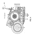
- Fig. 4 is a left side view of the automatic transmission.
- Fig. 5 is a perspective view of an electronic control unit, rotation sensors, and a manual valve, etc.
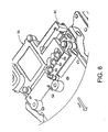
- Fig. 6 is a perspective view of the electronic control unit and the rotation sensors.
- Fig. 7 is a partial cross-sectional view of a containing space in which the electronic control unit is accommodated and its vicinity portion.
- Fig. 1 is a schematic diagram showing a configuration of an automatic transmission 1 according to an embodiment of the present invention.
- the automatic transmission 1 is particularly applied to an automobile in which an engine is side-mounted, such as a front-engine front-wheel drive (FF) vehicle.
- the automatic transmission 1 primarily includes a torque converter 3 attached to an engine output shaft 2, and a gear-shift mechanism 5 into which an output rotation of the torque converter 3 is inputted via an input shaft 4.
- the gear-shift mechanism 5 is at least partly accommodated inside a transmission case 6 in a state where it substantially is arranged on the axial center of the input shaft 4.
- the output rotation of the gear-shift mechanism 5 is transmitted to a differential device 9 via a counter-drive mechanism 8 from an output gear 7 that is similarly arranged on the axial center of the input shaft 4 at an intermediate position of the input shaft 4, and thereby axles 9a and 9b on the left and right sides are driven.
- the torque converter 3 preferably includes a case 3a coupled with the engine output shaft 2, a pump 3b fixed inside or to the case 3a, and a turbine 3c substantially oppositely arranged to the pump 3b and driven by the pump 3b through operating oil.
- the torque converter 3 also includes a stator 3e that is arranged between the pump 3b and the turbine 3c, and preferably is supported by the transmission case 6 via a one-way clutch 3d to increase engine torque, and a lock-up clutch 3f that is provided between the case 3a and the turbine 3c, and selectively directly connects the engine output shaft 2 and the turbine 3c via the case 3a.
- the rotation of the turbine 3c is transmitted to the gear-shift mechanism 5 via the input shaft 4.
- the gear-shift mechanism 5 includes first, second, and third planetary-gear sets 10, 20, and 30, respectively (hereinafter, simply referred to as "first, second, and third gear sets"). These are arranged inside the transmission case 6 substantially on the opposite side of the torque converter 3 from the output gear 7, in this order from the torque converter 3.
- a first clutch 40 and a second clutch 50 are arranged on or connected to the torque converter side from the output gear 7.
- a first brake 60, a second brake 70, and a third brake 80 are arranged in this order from the torque converter 3.
- a one-way clutch 90 is arranged in parallel with the first brake 60.
- each of the first, second, and third gear sets 10, 20, and 30 is a single pinion-type planetary-gear set.
- the gear set includes sun gears 11, 21, and 31, a plurality of pinions 12, 22, and 32 mating with the sun gears 11, 21, and 31, respectively, carriers 13, 23, and 33 supporting or carrying the pinions 12, 22, and 32, respectively, and ring gears 14, 24, and 34 mating with the pinions 12, 22, and 32, respectively.
- the input shaft 4 is coupled with or connected to the sun gear 31 of the third gear set 30.
- the sun gear 11 of the first gear set 10 and the sun gear 21 of the second gear set 20, the ring gear 14 of the first gear set 10 and the carrier 23 of the second gear set 20, and the ring gear 24 of the second gear set 20 and the carrier 33 of the third gear set 30 are mutually coupled.
- the output gear 7 is coupled with the carrier 13 of the first gear set 10.
- the sun gear 11 of the second gear set 10 and the sun gear 21 of the second gear set 20 are disconnectably coupled with the input shaft 4 via the first clutch 40.
- the carrier 23 of the second gear set 20 is disconnectably coupled with the input shaft 4 via the second clutch 50.
- the ring gear 14 of the first gear set 10 and the carrier 23 of the second gear set 20 are disconnectably coupled with the transmission case 6 via the first brake 60 and the one-way clutch 90 that are arranged in parallel to each other.
- the ring gear 24 of the second gear set 20 and the carrier 33 of the third gear set 30 are disconnectably coupled with the transmission case 6 via the second brake 70.
- the ring gear 34 of the third gear set 30 is disconnectably coupled with the transmission case 6 via the third brake 80.
- gear-shift mechanism 5 of this embodiment six forward gears and a reverse gear can be achieved by the coupling combination of the first and second clutches 40 and 50 and the first, second, and third brakes 60, 70, and 80.
- the relationship between the combinations and the gear positions is shown in the table of Fig. 2 .
- the first brake 60 is coupled only in the first gear where engine braking is achieved.
- the first gear is formed by locking the one-way clutch 90.
- the control device includes an electronic control unit 25 for controlling the gear shift with a control valve mechanism 250, such as a duty solenoid valve or an ON/OFF valve for (preferably hydraulically) controlling the friction-engaging elements of the gear-shift mechanism 5.
- a control valve mechanism 250 such as a duty solenoid valve or an ON/OFF valve for (preferably hydraulically) controlling the friction-engaging elements of the gear-shift mechanism 5.
- terms "front” and “rear,” and “left” and “right” represent front and rear, and left and right of the automobile, respectively, where Fig. 3 is a front view of the automatic transmission 1, and Fig. 4 shows a left side view of the automatic transmission 1.
- the automatic transmission 1 includes a primary shaft 26 coaxially provided with the engine, and onto which the gear-shift mechanism 5 is provided.
- the automatic transmission 1 also includes a secondary shaft 27 that is provided rearward and above the primary shaft 26 and is in parallel with the primary shaft 26.
- the automatic transmission 1 also includes a differential shaft 28 that is provided substantially rearward and below the primary shaft 26 and is in parallel with the primary shaft 26.
- a control-valve unit 41 is at least partly disposed in a substantially lower portion of the automatic transmission 1 so as to be at least partly located below the gear-shift mechanism 5 ( Fig. 1 ).
- the control-valve unit 41 includes three valve bodies 42, 43, and 44 that are piled or arranged in three layers substantially in the vertical direction, and an oil pan 45. Inside the valve bodies 42, 43, and 44, a manual valve 35 that moves so as to be interlocked with a range-switching operation of a shift lever 360 of the automobile, control valves for hydraulically controlling the friction-engaging elements, a plurality of accumulators, many oil channels, etc. are incorporated.
- the manual valve 35 is disposed in or near a front-end portion of the highest valve body 44, in parallel with the primary shaft 26 so that it moves substantially in the axial direction.
- a mechanical operation system 36, 37, and 38 for interlocking the shift lever 360 with the manual valve 35 is provided to or in connection with the manual valve 35.
- An engaging member 38 extends substantially downwardly from a rotary plate 37 at or near a lower end of a rotational shaft 36 of the operation system. The engaging member 38 engages with a disk member 35a at or near a tip end of the valve shaft of the manual valve 35.
- a shift position P, R, N, or D
- the transmission case 6 at least partly surrounding the gear-shift mechanism 5 includes a peripheral wall 51 along an outer perimeter of the rotating members, such as gears and drums.
- the peripheral wall 51 is opened substantially downwardly at or near a lower end, and the transmission case 6 also includes an outer wall 52 integrally or unitarily extending substantially forward from the peripheral wall 51 to be located adjacent to the peripheral wall 51.
- a containing space 53 preferably of an upwardly convex shape is formed above the valve body 44, and it contains the peripheral wall 51 of the transmission case 6, the outer wall 52, and the highest valve body 44.
- the containing space 53 is disposed forward side of the gear-shift mechanism 5, and the electronic control unit 25 is disposed inside the containing space 53.
- the electronic control unit 25 preferably has a control unit case made e.g. of a synthetic resin, at least one printed circuit board (not illustrated) at least partly accommodated inside the control unit case, and a computer or micro-computer (not illustrated) mounted on or connected to the printed circuit board.
- An integrated connector 25a to which a plurality of signal lines or power lines are connected is integrally or unitarily provided above and to a left end portion of the electronic control unit 25.
- the electronic control unit 25 includes a sensor mounting portion 25A integrally or unitarily formed therewith so that it continues laterally particularly to the right from the rear and right end portion of the electronic control unit 25.
- the sensor mounting portion 25A is also integrally or unitarily formed with a position detecting sensor 61 for detecting a moved position of the manual valve 35, and/or one or more rotation sensors 62, 63, and 64 for detecting rotation speeds of the rotating members of the gear-shift mechanism 5.
- the rotation sensors 62, 63, and 64 are integrally or unitarily formed with the electronic control unit 25.
- the rotation sensors 62, 63, and 64 preferably are formed so as to be inclined rearward (diagonally) from the electronic control unit 25.
- the rotation sensors 62, 63, and 64 are arranged at an angle different from 0° or 180° with respect to a longitudinal direction (e.g. the forward and backward direction) of the electronic control unit 25 (see e.g. FIGS. 5 and 6 ).
- the position detecting sensor 61 and the rotation sensors 62, 63, and 64 are connected to the electronic control unit 25 via one or more harnesses.
- the position detecting sensor 61 preferably is a potentiometer-type sensor.
- the position detecting sensor 61 includes a guide portion 61 a that is a level, rectangular groove substantially in the left-and-right direction, and a resistance body 61 b provided in an intermediate portion of the guide portion 61a.
- the position detecting sensor 61 also includes a movable member 61 c that is movable to the left and right along the guide portion 61 a, and an engaging member 61 d attached to the movable member 61 c for engaging with the disk member 35a of the manual valve 35.
- the moved position may be detected preferably based on the change in a value of electrical resistance.
- the rotation sensor 62 of this embodiment is an electromagnetic pickup sensor that detects a rotation of the input shaft 4 (i.e., turbine shaft).
- the rotation sensor 63 is an electromagnetic pickup sensor that detects a rotation of the valve member of the first clutch 40 (i.e., rotation of the first and second sun gears 11 and 21).
- the rotation sensor 64 is an electromagnetic pickup sensor that detects a rotation of the output gear 7.
- the rotation sensors 62, 63, and 64 and the electronic control unit 25 are disposed in this order from the torque converter 3.
- the electronic control unit 25 for controlling the gear shift 360 is provided inside the containing space 53 that is formed with the peripheral wall 51 of the transmission case 6, the outer wall 52 of the transmission case 6 is provided adjacent to the peripheral wall 51 and the valve body 44. Further, forward and immediately below the gear-shift mechanism 5, there may be a dead space inside the outer wall 52 of the transmission case 6.
- the dead space may be effectively used by at least partly arranging the electronic control unit 25 at the dead space, which is departed from the gear-shift mechanism 5.
- the electronic control unit 25 may be arranged within an internal space of the transmission case 6 and at a position where the electronic control unit 25 will not be damaged by hot oil dispersed from the gear-shift mechanism 5, thereby maintaining the durability of the electronic control unit 25.
- the present invention may be applied to a FF-three-shaft-type automatic transmission that includes the primary shaft 26, the secondary shaft 27, and the differential shaft or axis 28 to form the containing space 53 at a position forward side of the gear-shift mechanism 5.
- the electronic control unit 25 may be certainly arranged within the containing space 53.
- the electronic control unit 25 is arranged on the top portion of the valve body 44, lengths of the plurality of harnesses that connects the electronic control unit 25 with the solenoid 250 of the control valves may be shortened, thereby reducing the manufacturing cost. Further, in the above embodiment, because the rotation sensors 62, 63, and 64 are integrated with or included in the electronic control unit 25, harnesses or couplers for connecting the rotation sensors 62, 63, and 64 with the electronic control unit 25 may also be reduced in number.
- the electronic control unit 25 integrated with the rotation sensor(s) may be arranged at a higher position, thereby reducing the damages caused due to the scattered hot oil.
- the automatic transmission 1 includes the torque converter 3, and because the rotation sensors 62, 63, and 64 and the electronic control unit 25 are arranged in this order from the torque converter 3, the electronic control unit 25 may be arranged at a position distant from the torque converter 3 that is easy to increase in temperature.
- the position detecting sensor 61 for detecting the moved position of the manual valve 35 is provided, and the position detecting sensor 61 is integrated with the electronic control unit 25.
- the harnesses and couplers connecting the position detecting sensor 61 with the electronic control unit 25 may be reduced in number, thereby arranging the position detecting sensor 61 compactly.
- the manual valve 35 is disposed in parallel with the primary shaft 26 to move substantially in the axial direction. Thus, it may be possible to compactly arrange the manual valve 35.
- the manual valve 35 is provided to the highest valve body 44 among the plurality of valve bodies 42, 43, and 44.
- the electronic control unit 25 is arranged on or near the top portion of the highest valve body 44.
- the electronic control unit 25 may be arranged at a higher position to reduce the potential thermal damage.
- the present invention is applied to the automatic transmission of the automobile with a side-mounted engine. It should be appreciated by those skilled in the art that the present invention may also be applied to automatic transmissions other than those of the automobile with the side-mounted engine.
- control-valve unit of the automatic transmission is provided with three valve bodies piled in three layers. It should be appreciated by those skilled in the art that the valve bodies may be two instead of three, and may also be one.
Landscapes
- Engineering & Computer Science (AREA)
- General Engineering & Computer Science (AREA)
- Mechanical Engineering (AREA)
- Control Of Transmission Device (AREA)
- Gear-Shifting Mechanisms (AREA)
Abstract
Description
- The present description relates to automatic transmissions. More particularly, the description pertains to automatic transmissions having a transmission case in which an electric control unit is located while avoiding thermal damage to the electric control unit from high temperature hydraulic oil.
- Some automatic transmissions installed in automobiles are configured to change a power-flow path by changing an engagement state of plural friction elements to select a certain gear from among plural gears having different gear ratios.
- In some automatic transmissions, a control valve unit incorporating plural electromagnetic control units for changing an oil passage in a hydraulic system for engaging or disengaging the friction elements is integrally located on a lower side of a gear shift mechanism.
- In recent years, the number of selectable gears in automatic transmissions has been increased to improve travelling performance and/or fuel-efficiency of an automobile.
- In some conventional automatic transmissions, an electric control unit for controlling the control valve unit is located outside of a transmission case.
- But this design has a disadvantage of high manufacturing cost in the case where the automatic transmission has a relatively high number of selectable gears, since it requires many lengthy harnesses for connecting the electric control unit to the large number of control valves corresponding to the high number of selectable gears.
- One technology for addressing this disadvantage has been developed, in the form of an automatic transmission for an automobile including a harness integrated insulating sheet and an electric control unit located on the upper side of a valve body of a control valve unit immediately beneath a gear shift mechanism. The reference further discloses a plastic protective cover that covers above the electric control unit, and a rotation sensor, oil temperature sensor and oil pressure sensor that are provided in the harness integrated insulating sheet at an outside of the plastic protective cover. One example of such an automatic transmission is described by
U.S. Pat. No. 6,530,856 . - However, the inventor herein has recognized a disadvantage with such approaches. Specifically, although the automatic transmission described in above reference can shorten the length of harnesses for connecting an electric control unit with electromagnetic control valves, by locating the electric control unit on the upper side of a valve body of a control valve unit immediately beneath a gear shift mechanism via a harness integrated insulating sheet, the electric control unit can experience thermal damage from high temperature oil for cooling the gear shift mechanism dispersed from the gear shift mechanism, which usually contacts the upper surface of the plastic protective cover, thereby decreasing the durability of the electric control unit.
Accordingly, it is an object to provide an automatic transmission which reduces a risk of thermal damage to components thereof.
This object is solved according to the invention by the features of the independent claims. Preferred embodiments of the invention are subject of the dependent claims. - A first aspect of the present invention includes an automatic transmission including a valve body including control valves for (particularly hydraulically) controlling a friction engaging element provided within said transmission. The automatic transmission may further include an electric control unit located on or near said valve body for controlling gear shifting of said automatic transmission. The automatic transmission may further include a transmission case having a peripheral wall for at least partially enclosing a gear shift mechanism and an outer wall provided adjacent to said peripheral wall, wherein said electric control unit is at least partly, preferably substantially completely located within a containing space surrounded by said peripheral wall, said outer wall and said valve body.
- This automatic transmission overcomes at least some of the disadvantages of above reference.
- Since an electric control unit is at least partly located within a containing space formed by a peripheral wall, an outer wall provided adjacent to the peripheral wall and a valve body, the electric control unit can be located offset forwardly from immediately beneath the gear shift mechanism particularly by utilizing a dead space formed inside of the outer wall of the transmission case. Accordingly, the electric unit can be located in a position where it does not experience heat damage from high temperature oil dispersed from the gear shift mechanism while the electric unit is located inside of the transmission case, thereby, preventing durability decreasing of the electric control unit.
- A second aspect of the present invention includes an automatic transmission including a valve body including control valves for hydraulically controlling a friction engaging element provided within said transmission, and an electric control unit located on said valve body for controlling gear shifting of said automatic transmission. The automatic transmission may further include a transmission case having a peripheral wall for at least partially enclosing a gear shift mechanism, an outer wall provided adjacent to said peripheral wall, and a containing space surrounded by said peripheral wall, said outer wall and said valve body such that a shape of said containing space is convex upward, wherein said electric control unit is at least partly located within said containing space.
- This automatic transmission also overcomes at least some of the disadvantages of above reference.
- In an example embodiment, the automatic transmission may further comprise a primary shaft coaxially positioned relative to an engine output shaft and provided in said gear shift mechanism, a secondary shaft extending parallel to and located above and behind said primary shaft, and a differential axis extending parallel to and located below and behind said primary shaft. Preferably, said valve body is located under said gear shift mechanism, and said containing space is positioned on a forward side of said gear shift mechanism..
- In another example embodiment, the automatic transmission further comprises at least one rotation sensor for detecting a rotation speed of a designated rotating element of said gear shift mechanism, wherein said rotation sensor is integrated with and extending diagonally from said electric control unit.
- In another example embodiment, the automatic transmission further comprises a torque convertor, wherein said rotation sensor is spatially positioned intermediate said electric control unit and said torque convertor.
- In another example embodiment, the automatic transmission further comprises a manual valve provided in or on said valve body and moving in conjunction with a shift range changing operation via a shift lever, and a position detecting sensor for detecting a position of said manual valve. Preferably, said position detecting sensor is integrated with or mounted into said electric control unit.
- As a non limiting example, the manual valve is located parallel with said primary shaft and is configured to move substantially in an axial direction of the primary shaft.
- In one example embodiment, the valve body is one of a plurality of valve bodies, and the automatic transmission further comprises a control valve unit including the plurality of valve bodies stacked or arranged substantially in an up and down direction or vertical direction. Further, said manual valve is provided in a one of the valve bodies located on or near or at a top portion of said control valve unit, and said electric control unit is located on or near or at an upper side of said valve body located on or near or at the top portion of said control valve unit.
- A third aspect of the present invention includes an automatic transmission including a transmission case having a peripheral wall for at least partially enclosing a gear shift mechanism and an outer wall provided adjacent to said peripheral wall. The peripheral wall and outer wall of the transmission case are formed to at least partially define, with a valve body associated with the transmission case, a containing space sized to contain an electric control unit located on the valve body.
- In this way, at least some of the disadvantages of the related reference described above are overcome. These and other objects, features and advantages of the present invention will become more apparent upon reading of the following detailed description of preferred embodiments and accompanying drawings. It should be understood that even though embodiments are separately described, single features thereof may be combined to additional embodiments.
-
Fig. 1 is a schematic diagram showing an automatic transmission according to an embodiment of the present invention. -
Fig. 2 is a table showing a relationship between coupling combinations of friction-engaging elements and gear positions. -
Fig. 3 is a front view of the automatic transmission. -
Fig. 4 is a left side view of the automatic transmission. -
Fig. 5 is a perspective view of an electronic control unit, rotation sensors, and a manual valve, etc. -
Fig. 6 is a perspective view of the electronic control unit and the rotation sensors. -
Fig. 7 is a partial cross-sectional view of a containing space in which the electronic control unit is accommodated and its vicinity portion. - Hereafter, the best mode to implement the present invention will be explained based on the accompanying drawings.
-
Fig. 1 is a schematic diagram showing a configuration of anautomatic transmission 1 according to an embodiment of the present invention. In this embodiment, theautomatic transmission 1 is particularly applied to an automobile in which an engine is side-mounted, such as a front-engine front-wheel drive (FF) vehicle. Theautomatic transmission 1 primarily includes a torque converter 3 attached to anengine output shaft 2, and a gear-shift mechanism 5 into which an output rotation of the torque converter 3 is inputted via aninput shaft 4. The gear-shift mechanism 5 is at least partly accommodated inside atransmission case 6 in a state where it substantially is arranged on the axial center of theinput shaft 4. - The output rotation of the gear-
shift mechanism 5 is transmitted to adifferential device 9 via a counter-drive mechanism 8 from an output gear 7 that is similarly arranged on the axial center of theinput shaft 4 at an intermediate position of theinput shaft 4, and thereby axles 9a and 9b on the left and right sides are driven. - The torque converter 3 preferably includes a
case 3a coupled with theengine output shaft 2, apump 3b fixed inside or to thecase 3a, and aturbine 3c substantially oppositely arranged to thepump 3b and driven by thepump 3b through operating oil. The torque converter 3 also includes a stator 3e that is arranged between thepump 3b and theturbine 3c, and preferably is supported by thetransmission case 6 via a one-way clutch 3d to increase engine torque, and a lock-up clutch 3f that is provided between thecase 3a and theturbine 3c, and selectively directly connects theengine output shaft 2 and theturbine 3c via thecase 3a. The rotation of theturbine 3c is transmitted to the gear-shift mechanism 5 via theinput shaft 4. - The gear-
shift mechanism 5 includes first, second, and third planetary-gear sets transmission case 6 substantially on the opposite side of the torque converter 3 from the output gear 7, in this order from the torque converter 3. - As friction-engaging elements constituting or forming part of the gear-
shift mechanism 5, afirst clutch 40 and asecond clutch 50 are arranged on or connected to the torque converter side from the output gear 7. On the substantially opposite side of the torque converter 3 from the output gear 7, afirst brake 60, asecond brake 70, and athird brake 80 are arranged in this order from the torque converter 3. A one-way clutch 90 is arranged in parallel with thefirst brake 60. - In this embodiment, each of the first, second, and
third gear sets sun gears 11, 21, and 31, a plurality ofpinions 12, 22, and 32 mating with thesun gears 11, 21, and 31, respectively,carriers pinions 12, 22, and 32, respectively, andring gears pinions 12, 22, and 32, respectively. - The
input shaft 4 is coupled with or connected to the sun gear 31 of the third gear set 30. Thesun gear 11 of the first gear set 10 and the sun gear 21 of the second gear set 20, thering gear 14 of the first gear set 10 and thecarrier 23 of the second gear set 20, and thering gear 24 of the second gear set 20 and thecarrier 33 of thethird gear set 30 are mutually coupled. The output gear 7 is coupled with thecarrier 13 of the first gear set 10. - The
sun gear 11 of the second gear set 10 and the sun gear 21 of the second gear set 20 are disconnectably coupled with theinput shaft 4 via thefirst clutch 40. Thecarrier 23 of the second gear set 20 is disconnectably coupled with theinput shaft 4 via thesecond clutch 50. - The
ring gear 14 of the first gear set 10 and thecarrier 23 of the second gear set 20 are disconnectably coupled with thetransmission case 6 via thefirst brake 60 and the one-way clutch 90 that are arranged in parallel to each other. Thering gear 24 of the second gear set 20 and thecarrier 33 of the third gear set 30 are disconnectably coupled with thetransmission case 6 via thesecond brake 70. Thering gear 34 of the third gear set 30 is disconnectably coupled with thetransmission case 6 via thethird brake 80. - As described above, according to the gear-
shift mechanism 5 of this embodiment, six forward gears and a reverse gear can be achieved by the coupling combination of the first andsecond clutches third brakes Fig. 2 . - Here, the
first brake 60 is coupled only in the first gear where engine braking is achieved. In the first gear when the engine braking is not generated, the first gear is formed by locking the one-way clutch 90. - Next, a control device of the
automatic transmission 1 will be explained based onFigs. 3-7 . The control device includes anelectronic control unit 25 for controlling the gear shift with acontrol valve mechanism 250, such as a duty solenoid valve or an ON/OFF valve for (preferably hydraulically) controlling the friction-engaging elements of the gear-shift mechanism 5. Hereinafter, terms "front" and "rear," and "left" and "right" represent front and rear, and left and right of the automobile, respectively, whereFig. 3 is a front view of theautomatic transmission 1, andFig. 4 shows a left side view of theautomatic transmission 1. - The
automatic transmission 1 includes aprimary shaft 26 coaxially provided with the engine, and onto which the gear-shift mechanism 5 is provided. Theautomatic transmission 1 also includes asecondary shaft 27 that is provided rearward and above theprimary shaft 26 and is in parallel with theprimary shaft 26. Theautomatic transmission 1 also includes adifferential shaft 28 that is provided substantially rearward and below theprimary shaft 26 and is in parallel with theprimary shaft 26. - A control-
valve unit 41 is at least partly disposed in a substantially lower portion of theautomatic transmission 1 so as to be at least partly located below the gear-shift mechanism 5 (Fig. 1 ). The control-valve unit 41 includes threevalve bodies oil pan 45. Inside thevalve bodies manual valve 35 that moves so as to be interlocked with a range-switching operation of ashift lever 360 of the automobile, control valves for hydraulically controlling the friction-engaging elements, a plurality of accumulators, many oil channels, etc. are incorporated. - As shown in
Figs. 3 and5 , themanual valve 35 is disposed in or near a front-end portion of thehighest valve body 44, in parallel with theprimary shaft 26 so that it moves substantially in the axial direction. Amechanical operation system shift lever 360 with themanual valve 35 is provided to or in connection with themanual valve 35. An engagingmember 38 extends substantially downwardly from arotary plate 37 at or near a lower end of arotational shaft 36 of the operation system. The engagingmember 38 engages with adisk member 35a at or near a tip end of the valve shaft of themanual valve 35. Thus, according to a shift position (P, R, N, or D) selected by a driver who operates theshift lever 360, themanual valve 35 moves substantially in the axial direction via the mechanical operation system. - As shown in
Figs. 5-7 , thetransmission case 6 at least partly surrounding the gear-shift mechanism 5 includes aperipheral wall 51 along an outer perimeter of the rotating members, such as gears and drums. Theperipheral wall 51 is opened substantially downwardly at or near a lower end, and thetransmission case 6 also includes anouter wall 52 integrally or unitarily extending substantially forward from theperipheral wall 51 to be located adjacent to theperipheral wall 51. A containingspace 53 preferably of an upwardly convex shape is formed above thevalve body 44, and it contains theperipheral wall 51 of thetransmission case 6, theouter wall 52, and thehighest valve body 44. The containingspace 53 is disposed forward side of the gear-shift mechanism 5, and theelectronic control unit 25 is disposed inside the containingspace 53. - The
electronic control unit 25 preferably has a control unit case made e.g. of a synthetic resin, at least one printed circuit board (not illustrated) at least partly accommodated inside the control unit case, and a computer or micro-computer (not illustrated) mounted on or connected to the printed circuit board. Anintegrated connector 25a to which a plurality of signal lines or power lines are connected is integrally or unitarily provided above and to a left end portion of theelectronic control unit 25. - The
electronic control unit 25 includes asensor mounting portion 25A integrally or unitarily formed therewith so that it continues laterally particularly to the right from the rear and right end portion of theelectronic control unit 25. Thesensor mounting portion 25A is also integrally or unitarily formed with aposition detecting sensor 61 for detecting a moved position of themanual valve 35, and/or one ormore rotation sensors shift mechanism 5. Therotation sensors electronic control unit 25. Therotation sensors electronic control unit 25. In other words, therotation sensors
FIGS. 5 and6 ). Theposition detecting sensor 61 and therotation sensors electronic control unit 25 via one or more harnesses. - The
position detecting sensor 61 preferably is a potentiometer-type sensor. Theposition detecting sensor 61 includes aguide portion 61 a that is a level, rectangular groove substantially in the left-and-right direction, and aresistance body 61 b provided in an intermediate portion of theguide portion 61a. Theposition detecting sensor 61 also includes amovable member 61 c that is movable to the left and right along theguide portion 61 a, and an engagingmember 61 d attached to themovable member 61 c for engaging with thedisk member 35a of themanual valve 35. - When the
manual valve 35 is switched by the operation of theshift lever 360, because themovable member 61 c also integrally or unitarily moves to a position corresponding to the shift position via the engagingmember 61 d, the moved position may be detected preferably based on the change in a value of electrical resistance. - Particularly, as shown in
Figs. 1 ,5 , and6 , therotation sensor 62 of this embodiment is an electromagnetic pickup sensor that detects a rotation of the input shaft 4 (i.e., turbine shaft). Therotation sensor 63 is an electromagnetic pickup sensor that detects a rotation of the valve member of the first clutch 40 (i.e., rotation of the first and second sun gears 11 and 21). Therotation sensor 64 is an electromagnetic pickup sensor that detects a rotation of the output gear 7. As shown inFig. 1 , therotation sensors electronic control unit 25 are disposed in this order from the torque converter 3. - Next, operations and effects of the control device of the
automatic transmission 1 will be explained. - As described above, the
electronic control unit 25 for controlling thegear shift 360 is provided inside the containingspace 53 that is formed with theperipheral wall 51 of thetransmission case 6, theouter wall 52 of thetransmission case 6 is provided adjacent to theperipheral wall 51 and thevalve body 44. Further, forward and immediately below the gear-shift mechanism 5, there may be a dead space inside theouter wall 52 of thetransmission case 6. The dead space may be effectively used by at least partly arranging theelectronic control unit 25 at the dead space, which is departed from the gear-shift mechanism 5. Thus, theelectronic control unit 25 may be arranged within an internal space of thetransmission case 6 and at a position where theelectronic control unit 25 will not be damaged by hot oil dispersed from the gear-shift mechanism 5, thereby maintaining the durability of theelectronic control unit 25. - The present invention may be applied to a FF-three-shaft-type automatic transmission that includes the
primary shaft 26, thesecondary shaft 27, and the differential shaft oraxis 28 to form the containingspace 53 at a position forward side of the gear-shift mechanism 5. Thus, theelectronic control unit 25 may be certainly arranged within the containingspace 53. - In the above embodiment, because the
electronic control unit 25 is arranged on the top portion of thevalve body 44, lengths of the plurality of harnesses that connects theelectronic control unit 25 with thesolenoid 250 of the control valves may be shortened, thereby reducing the manufacturing cost. Further, in the above embodiment, because therotation sensors electronic control unit 25, harnesses or couplers for connecting therotation sensors electronic control unit 25 may also be reduced in number. Further, in the above embodiment, because therotation sensors electronic control unit 25, theelectronic control unit 25 integrated with the rotation sensor(s) may be arranged at a higher position, thereby reducing the damages caused due to the scattered hot oil. Further, in the above embodiment, because theautomatic transmission 1 includes the torque converter 3, and because therotation sensors electronic control unit 25 are arranged in this order from the torque converter 3, theelectronic control unit 25 may be arranged at a position distant from the torque converter 3 that is easy to increase in temperature. - Further, in the above embodiment, the
position detecting sensor 61 for detecting the moved position of themanual valve 35 is provided, and theposition detecting sensor 61 is integrated with theelectronic control unit 25. Thus, the harnesses and couplers connecting theposition detecting sensor 61 with theelectronic control unit 25 may be reduced in number, thereby arranging theposition detecting sensor 61 compactly. - Further, in the above embodiment, the
manual valve 35 is disposed in parallel with theprimary shaft 26 to move substantially in the axial direction. Thus, it may be possible to compactly arrange themanual valve 35. - Further, in the above embodiment, the
manual valve 35 is provided to thehighest valve body 44 among the plurality ofvalve bodies electronic control unit 25 is arranged on or near the top portion of thehighest valve body 44. Thus, theelectronic control unit 25 may be arranged at a higher position to reduce the potential thermal damage. - Next, an example in which the above embodiment is partially changed will be explained.
- In the above embodiment, the present invention is applied to the automatic transmission of the automobile with a side-mounted engine. It should be appreciated by those skilled in the art that the present invention may also be applied to automatic transmissions other than those of the automobile with the side-mounted engine.
- In the above embodiment, the control-valve unit of the automatic transmission is provided with three valve bodies piled in three layers. It should be appreciated by those skilled in the art that the valve bodies may be two instead of three, and may also be one.
- In addition, a person skilled in the art may suitably modify the embodiment, and the modified embodiment may also be included in the scope of the present invention.
- It should be understood that the embodiments herein are illustrative and not restrictive, since the scope of the invention is defined by the appended claims rather than by the description preceding them, and all changes that fall within metes and bounds of the claims, or equivalence of such metes and bounds thereof are therefore intended to be embraced by the claims.
Claims (11)
- An automatic transmission (1) comprising:a valve body (44) including control valves for controlling at least one friction engaging element provided within said transmission (1);an electric control unit (25) located on or near said valve body (44) for controlling gear shifting of said automatic transmission (1); anda transmission case (6) having a peripheral wall (51) for at least partially enclosing a gear shift mechanism (5) and an outer wall (52) provided adjacent to said peripheral wall (51),wherein said electric control unit (25) is at least partly located within a containing space (53) surrounded by said peripheral wall (51), said outer wall (52) and said valve body (44).
- The automatic transmission as described in claim 1, further comprising:a primary shaft (26) coaxially positioned relative to an engine output shaft (2) and provided in said gear shift mechanism (5);a secondary shaft (27) extending parallel to and located above and behind said primary shaft (26); anda differential axis (28) extending parallel to and located below and behind said primary shaft (26).
- The automatic transmission as described in any one of the preceding claims, wherein said valve body (44) is located under said gear shift mechanism (5), and said containing space (53) is positioned on a forward side of said gear shift mechanism (5).
- The automatic transmission as described in any one of the preceding claims, further comprising at least one rotation sensor (62; 63; 64) for detecting a rotation speed of a designated rotating element of said gear shift mechanism (5),
wherein said rotation sensor (62; 63; 64) is integrated with and extending diagonally from said electric control unit (25). - The automatic transmission as described in claim 4, further comprising a torque convertor (3),
wherein said rotation sensor (62; 63; 64) is spatially positioned intermediate said electric control unit (25) and said torque convertor (3). - The automatic transmission as described in any one of the preceding claims, further comprising:a manual valve (35) provided in or on said valve body (44) and moving in conjunction with a shift range changing operation via a shift lever (360); anda position detecting sensor (61) for detecting a position of said manual valve (35).
- The automatic transmission as described in claim 6, wherein said position detecting sensor (61) is integrated with said electric control unit (25).
- The automatic transmission as described in claim 6 or 7 in combination with claim 2, wherein said manual valve (35) is located parallel with said primary shaft (26) and is configured to move substantially in an axial direction of the primary shaft (26).
- The automatic transmission as described in any one of the preceding claims 6 to 8,
wherein the valve body (44) is one of a plurality of valve bodies (42-44), the automatic transmission (1) further comprising:a control valve unit (41) including the plurality of valve bodies (42-44) stacked substantially in an up and down direction;wherein said manual valve (35) is provided in a one (44) of the valve bodies (42-44) located on or near a top portion of said control valve unit (41); and
wherein said electric control unit (25) is located on or near an upper side of said valve body (44) located on or near the top portion of said control valve unit (41). - The automatic transmission as described in any one of the preceding claims,
wherein a shape of said containing space (53) is convex upward. - An automatic transmission, in particular according to any one of the preceding claims, comprising:a transmission case (6) having a peripheral wall (51) for at least partially enclosing a gear shift mechanism (5) and an outer wall (52) provided adjacent to said peripheral wall (51), the peripheral wall (51) and outer wall (52) of the transmission case (6) being formed to at least partially define, with a valve body (44) associated with the transmission case (6), a containing space (53) sized to contain an electric control unit (25) located on the valve body (44).
Applications Claiming Priority (2)
| Application Number | Priority Date | Filing Date | Title |
|---|---|---|---|
| JP2007254070A JP5071648B2 (en) | 2007-09-28 | 2007-09-28 | Control device for automatic transmission |
| JP2007254071A JP5071649B2 (en) | 2007-09-28 | 2007-09-28 | Control device for automatic transmission |
Publications (3)
| Publication Number | Publication Date |
|---|---|
| EP2042775A2 true EP2042775A2 (en) | 2009-04-01 |
| EP2042775A3 EP2042775A3 (en) | 2009-08-26 |
| EP2042775B1 EP2042775B1 (en) | 2010-11-17 |
Family
ID=40251551
Family Applications (1)
| Application Number | Title | Priority Date | Filing Date |
|---|---|---|---|
| EP08015635A Ceased EP2042775B1 (en) | 2007-09-28 | 2008-09-04 | Automatic Transmission |
Country Status (3)
| Country | Link |
|---|---|
| US (1) | US8210975B2 (en) |
| EP (1) | EP2042775B1 (en) |
| DE (1) | DE602008003501D1 (en) |
Cited By (2)
| Publication number | Priority date | Publication date | Assignee | Title |
|---|---|---|---|---|
| US9009941B2 (en) | 2010-03-10 | 2015-04-21 | Mazda Motor Corporation | Method for manufacturing automatic transmission |
| CN111396533A (en) * | 2020-04-19 | 2020-07-10 | 山西三强新能源科技有限公司 | System for monitoring operation of chain transmission device in carbon black production |
Families Citing this family (5)
| Publication number | Priority date | Publication date | Assignee | Title |
|---|---|---|---|---|
| DE102005012257A1 (en) * | 2005-03-17 | 2006-09-28 | Zf Friedrichshafen Ag | Arrangement of the temperature sensor in an automatic transmission |
| JP5365552B2 (en) * | 2010-03-09 | 2013-12-11 | マツダ株式会社 | Control device for automatic transmission |
| JP5395853B2 (en) * | 2011-08-10 | 2014-01-22 | 本田技研工業株式会社 | Control device for automatic transmission |
| CN104455340B (en) * | 2014-11-21 | 2017-04-05 | 盛瑞传动股份有限公司 | A kind of automatic gear-box and its assembly method |
| DE102019203238A1 (en) * | 2019-03-11 | 2020-09-17 | Zf Friedrichshafen Ag | Hydraulic control unit for a transmission |
Citations (1)
| Publication number | Priority date | Publication date | Assignee | Title |
|---|---|---|---|---|
| US6530856B1 (en) | 2000-06-28 | 2003-03-11 | Unisia Jecs Corporation | Electronic control apparatus for vehicle |
Family Cites Families (15)
| Publication number | Priority date | Publication date | Assignee | Title |
|---|---|---|---|---|
| JPH0810026B2 (en) * | 1985-01-19 | 1996-01-31 | アイシン・エィ・ダブリュ 株式会社 | Transmission control device |
| JPH06159491A (en) | 1992-11-30 | 1994-06-07 | Mazda Motor Corp | Valve body mounting structure for automatic transmission |
| JP2959357B2 (en) | 1993-09-29 | 1999-10-06 | 日産自動車株式会社 | Control valve unit for continuously variable transmission |
| DE19710931B4 (en) | 1996-03-27 | 2007-08-16 | Volkswagen Ag | Automatic transmission with integrated control electronics |
| US6205887B1 (en) * | 1997-02-06 | 2001-03-27 | Audi Ag | Automatic electrohydraulically controlled transmission |
| DE19745537B4 (en) | 1997-10-15 | 2006-04-20 | Siemens Ag | Electronic control unit for accommodation in a motor vehicle automatic transmission |
| JP3642681B2 (en) | 1998-05-22 | 2005-04-27 | ジヤトコ株式会社 | Structure of hydraulic control valve for automatic transmission |
| DE19855319A1 (en) * | 1998-12-01 | 2000-06-08 | Zf Batavia Llc | Arrangement of an electronics unit and a hydraulic unit of a control unit for an automatic transmission of a motor vehicle |
| JP3980292B2 (en) | 2001-05-08 | 2007-09-26 | ジヤトコ株式会社 | Automatic transmission vehicle speed sensor mounting structure |
| JP4020240B2 (en) | 2001-07-10 | 2007-12-12 | ジヤトコ株式会社 | Lubrication structure in continuously variable transmission |
| DE10223433A1 (en) * | 2002-05-25 | 2003-12-18 | Voith Turbo Kg | Gear housing and gear unit |
| DE102005021862A1 (en) | 2005-05-11 | 2006-11-23 | Zf Transmission Technologies L.L.C., Batavia | Automatic automotive gearbox has a selector lever and selector shaft operating in conjunction with a selector pusher |
| DE102005021761A1 (en) * | 2005-05-11 | 2006-11-30 | Zf Friedrichshafen Ag | Multi-component transmission for commercial vehicles comprises a gear regulator having an actuator unit with a working cylinder |
| DE102005028122A1 (en) | 2005-06-10 | 2006-12-14 | Getrag Getriebe- Und Zahnradfabrik Hermann Hagenmeyer Gmbh & Cie Kg | Automated countershaft transmission and method for its manufacture |
| JP4619257B2 (en) * | 2005-10-03 | 2011-01-26 | トヨタ自動車株式会社 | Automatic transmission |
-
2008
- 2008-08-27 US US12/199,620 patent/US8210975B2/en not_active Expired - Fee Related
- 2008-09-04 EP EP08015635A patent/EP2042775B1/en not_active Ceased
- 2008-09-04 DE DE602008003501T patent/DE602008003501D1/en active Active
Patent Citations (1)
| Publication number | Priority date | Publication date | Assignee | Title |
|---|---|---|---|---|
| US6530856B1 (en) | 2000-06-28 | 2003-03-11 | Unisia Jecs Corporation | Electronic control apparatus for vehicle |
Cited By (2)
| Publication number | Priority date | Publication date | Assignee | Title |
|---|---|---|---|---|
| US9009941B2 (en) | 2010-03-10 | 2015-04-21 | Mazda Motor Corporation | Method for manufacturing automatic transmission |
| CN111396533A (en) * | 2020-04-19 | 2020-07-10 | 山西三强新能源科技有限公司 | System for monitoring operation of chain transmission device in carbon black production |
Also Published As
| Publication number | Publication date |
|---|---|
| EP2042775B1 (en) | 2010-11-17 |
| EP2042775A3 (en) | 2009-08-26 |
| US8210975B2 (en) | 2012-07-03 |
| US20090088281A1 (en) | 2009-04-02 |
| DE602008003501D1 (en) | 2010-12-30 |
Similar Documents
| Publication | Publication Date | Title |
|---|---|---|
| EP2042775B1 (en) | Automatic Transmission | |
| EP2478257B1 (en) | Multiple clutch transmission | |
| CN100425868C (en) | Double clutch transmission | |
| US6286381B1 (en) | Gear preselect system for an electro-mechanical automatic transmission having dual input shafts | |
| CN102797838B (en) | Manual transmission clutch proterctive equipment | |
| US7833120B2 (en) | Automatic transmission for vehicles | |
| EP0029711A2 (en) | Rotary power transmission | |
| EP2221512B1 (en) | Hydraulic control device of automatic transmission | |
| CN111810598B (en) | Method and system for an electric drive arrangement | |
| EP1190888A2 (en) | Vehicle transmission system with transmission input clutch | |
| US20180172084A1 (en) | Electronic clutch actuator | |
| EP1013972A1 (en) | Apparatus for detecting gear positions of automobile transmission | |
| US6544142B2 (en) | Transmission system for vehicle | |
| JP5071648B2 (en) | Control device for automatic transmission | |
| US6878095B2 (en) | Automatic-clutch control system of automatic clutch type transmission | |
| EP0034412A2 (en) | Rotary power transmission | |
| US20180172085A1 (en) | System and method for clutch actuation having electronic clutch actuator with manual operation | |
| WO2021039032A1 (en) | Power unit of utility vehicle | |
| WO2021039033A1 (en) | Power unit of utility vehicle | |
| JP5071649B2 (en) | Control device for automatic transmission | |
| US10563732B2 (en) | Power transmission device | |
| US20180172087A1 (en) | System and method for clutch actuation having electronic clutch actuator with integrated manual operation | |
| WO2021039036A1 (en) | Power unit of utility vehicle | |
| US7476173B2 (en) | Park inhibit solenoid assembly and system incorporating the same | |
| WO2026058270A1 (en) | A multi-mode transmission for a vehicle and a shift assembly thereof |
Legal Events
| Date | Code | Title | Description |
|---|---|---|---|
| PUAI | Public reference made under article 153(3) epc to a published international application that has entered the european phase |
Free format text: ORIGINAL CODE: 0009012 |
|
| AK | Designated contracting states |
Kind code of ref document: A2 Designated state(s): AT BE BG CH CY CZ DE DK EE ES FI FR GB GR HR HU IE IS IT LI LT LU LV MC MT NL NO PL PT RO SE SI SK TR |
|
| AX | Request for extension of the european patent |
Extension state: AL BA MK RS |
|
| PUAL | Search report despatched |
Free format text: ORIGINAL CODE: 0009013 |
|
| AK | Designated contracting states |
Kind code of ref document: A3 Designated state(s): AT BE BG CH CY CZ DE DK EE ES FI FR GB GR HR HU IE IS IT LI LT LU LV MC MT NL NO PL PT RO SE SI SK TR |
|
| AX | Request for extension of the european patent |
Extension state: AL BA MK RS |
|
| 17P | Request for examination filed |
Effective date: 20100204 |
|
| AKX | Designation fees paid |
Designated state(s): DE |
|
| GRAP | Despatch of communication of intention to grant a patent |
Free format text: ORIGINAL CODE: EPIDOSNIGR1 |
|
| GRAS | Grant fee paid |
Free format text: ORIGINAL CODE: EPIDOSNIGR3 |
|
| GRAA | (expected) grant |
Free format text: ORIGINAL CODE: 0009210 |
|
| AK | Designated contracting states |
Kind code of ref document: B1 Designated state(s): DE |
|
| REF | Corresponds to: |
Ref document number: 602008003501 Country of ref document: DE Date of ref document: 20101230 Kind code of ref document: P |
|
| REG | Reference to a national code |
Ref country code: DE Ref legal event code: R084 Ref document number: 602008003501 Country of ref document: DE Effective date: 20110622 Ref country code: DE Ref legal event code: R084 Ref document number: 602008003501 Country of ref document: DE Effective date: 20110531 |
|
| PLBE | No opposition filed within time limit |
Free format text: ORIGINAL CODE: 0009261 |
|
| STAA | Information on the status of an ep patent application or granted ep patent |
Free format text: STATUS: NO OPPOSITION FILED WITHIN TIME LIMIT |
|
| 26N | No opposition filed |
Effective date: 20110818 |
|
| REG | Reference to a national code |
Ref country code: DE Ref legal event code: R097 Ref document number: 602008003501 Country of ref document: DE Effective date: 20110818 |
|
| PGFP | Annual fee paid to national office [announced via postgrant information from national office to epo] |
Ref country code: DE Payment date: 20200826 Year of fee payment: 13 |
|
| REG | Reference to a national code |
Ref country code: DE Ref legal event code: R119 Ref document number: 602008003501 Country of ref document: DE |
|
| PG25 | Lapsed in a contracting state [announced via postgrant information from national office to epo] |
Ref country code: DE Free format text: LAPSE BECAUSE OF NON-PAYMENT OF DUE FEES Effective date: 20220401 |