EP2042736A2 - Direct joint system for drive shaft-flexible rotor for self-priming pumps - Google Patents
Direct joint system for drive shaft-flexible rotor for self-priming pumps Download PDFInfo
- Publication number
- EP2042736A2 EP2042736A2 EP08015679A EP08015679A EP2042736A2 EP 2042736 A2 EP2042736 A2 EP 2042736A2 EP 08015679 A EP08015679 A EP 08015679A EP 08015679 A EP08015679 A EP 08015679A EP 2042736 A2 EP2042736 A2 EP 2042736A2
- Authority
- EP
- European Patent Office
- Prior art keywords
- rotor
- self
- flexible
- priming pumps
- rib
- Prior art date
- Legal status (The legal status is an assumption and is not a legal conclusion. Google has not performed a legal analysis and makes no representation as to the accuracy of the status listed.)
- Withdrawn
Links
Images

Classifications
-
- F—MECHANICAL ENGINEERING; LIGHTING; HEATING; WEAPONS; BLASTING
- F04—POSITIVE - DISPLACEMENT MACHINES FOR LIQUIDS; PUMPS FOR LIQUIDS OR ELASTIC FLUIDS
- F04C—ROTARY-PISTON, OR OSCILLATING-PISTON, POSITIVE-DISPLACEMENT MACHINES FOR LIQUIDS; ROTARY-PISTON, OR OSCILLATING-PISTON, POSITIVE-DISPLACEMENT PUMPS
- F04C5/00—Rotary-piston machines or pumps with the working-chamber walls at least partly resiliently deformable
-
- F—MECHANICAL ENGINEERING; LIGHTING; HEATING; WEAPONS; BLASTING
- F04—POSITIVE - DISPLACEMENT MACHINES FOR LIQUIDS; PUMPS FOR LIQUIDS OR ELASTIC FLUIDS
- F04C—ROTARY-PISTON, OR OSCILLATING-PISTON, POSITIVE-DISPLACEMENT MACHINES FOR LIQUIDS; ROTARY-PISTON, OR OSCILLATING-PISTON, POSITIVE-DISPLACEMENT PUMPS
- F04C13/00—Adaptations of machines or pumps for special use, e.g. for extremely high pressures
- F04C13/001—Pumps for particular liquids
-
- F—MECHANICAL ENGINEERING; LIGHTING; HEATING; WEAPONS; BLASTING
- F04—POSITIVE - DISPLACEMENT MACHINES FOR LIQUIDS; PUMPS FOR LIQUIDS OR ELASTIC FLUIDS
- F04C—ROTARY-PISTON, OR OSCILLATING-PISTON, POSITIVE-DISPLACEMENT MACHINES FOR LIQUIDS; ROTARY-PISTON, OR OSCILLATING-PISTON, POSITIVE-DISPLACEMENT PUMPS
- F04C15/00—Component parts, details or accessories of machines, pumps or pumping installations, not provided for in groups F04C2/00 - F04C14/00
- F04C15/0057—Driving elements, brakes, couplings, transmission specially adapted for machines or pumps
- F04C15/0061—Means for transmitting movement from the prime mover to driven parts of the pump, e.g. clutches, couplings, transmissions
- F04C15/0073—Couplings between rotors and input or output shafts acting by interengaging or mating parts, i.e. positive coupling of rotor and shaft
-
- F—MECHANICAL ENGINEERING; LIGHTING; HEATING; WEAPONS; BLASTING
- F05—INDEXING SCHEMES RELATING TO ENGINES OR PUMPS IN VARIOUS SUBCLASSES OF CLASSES F01-F04
- F05C—INDEXING SCHEME RELATING TO MATERIALS, MATERIAL PROPERTIES OR MATERIAL CHARACTERISTICS FOR MACHINES, ENGINES OR PUMPS OTHER THAN NON-POSITIVE-DISPLACEMENT MACHINES OR ENGINES
- F05C2225/00—Synthetic polymers, e.g. plastics; Rubber
- F05C2225/02—Rubber
Definitions
- This invention refers to flexible rotors for self-priming pumps used for liquid and dense products.
- the flexible rotors used nowadays in self-priming pumps are made up of an annular body supplied externally with flexible radial wings. These wings are obtained by a press-molding operation starting from elastomeric material such as silicone rubbers, neoprene (Cr), nitrile (NBR) and the like or the materials known with the trade mark name DUTRAL (EPDM).
- elastomeric material such as silicone rubbers, neoprene (Cr), nitrile (NBR) and the like or the materials known with the trade mark name DUTRAL (EPDM).
- this last rotor had in the previous technics a metallic bush having a section or shape corresponding to shaft end.
- the bush was fixed into the rotor central hole during the press-molding phase of the body formed by the hub and radial wings. Obviously the presence of the internal bush, usually made of stainless steel, caused a rotor cost increase.
- a further drawback of the metal bush was the incompatibility with the acid materials that have the tendency to corrode easily metals, also metals resisting to oxidation such as the stainless steel.
- the bush external surface was sprinkled with a special glue or mastic. This construction did not allow its use in contact with foodstuffs according to European Community standards, also if the rotor, for example, was made of silicone certified for use with foodstuffs.
- the aim of this invention is to provide a rotor press-molded in a sole piece with flexible external wings suitable for being used in self-priming pumps for liquid and dense products that avoids the disadvantages of well-known rotors and that has a simple and very economical construction, and that has a sure coupling with the pump shaft and finally that it can be used in any industry field, such as the chemical, pharmaceutical, cosmetic, foodstuff, oenological, liqueur, gassed drink fields, etc. and also with corrosive acids and foodstuff materials.
- this aim is obtained creating a play between the shaft slot and the full rotor sector.
- the rotor is made up of flexible material and has, as integral part, the rotation coupling means with the shaped shaft end made for driving the pump, said means being also obtained by a press-molding phase together with the hub and radial wings.
- said means are made up of a rib or diametral wall having a valuable thickness that crosses the rotor hub hole and that is suitable to be engaged with a corresponding slot made on a pump shaft part.
- the rotor made of elastomeric material or the like, is not supplied with additional o glued components (bush), and then it is not subject to its removal due to breackage of glueing points and it is possible its use in all possible fields owing to the absence of metallic components.
- the rotor according to the invention is economical and has a long duration owing to its greater resistance.
- the Figure 2 shows, among other parts, the input coupling E and output coupling U of the pump.
- the shaft end A has a diametral slot K for being engaged by dry connection with the corresponding element made up of the rotor G, that is shown in more details in Figures 4 and 5 .
- Said rotor includes an annular body C provided externally with flexible radial wings R and, according to the invention, a diametral wall or rib D obtained by press-molding together with the body C and wings R.
- the press-molding operation is single and the used material is an elastomeric material and the like.
- Said rib D forms the rotor element foreseen to be inserted in the slot K of the element A for forming a sure rotation coupling among these parts.
- the construction solution of the rotor part foreseen to be engaged with the shaft can vary according to practical requirements. So, for example, instead of using a diametral rib, it can be used two ribs in cross form and also three radial ribs spaced by 120° with one another and, correspond-dingly, the shaft end shall have slots or grooves in cross layout or spaced by 120° with one another.
- FIG. 6 shows another construction solution in Figures 6 and 7 , in which the Figure 6 shows another type of shaft section with groove shaped as two trapeziums counterposed with one another owing to a second embodiment, and the Figure 7 shows a central rotor part related to said second embodiment with central hole having the form of two trapeziums.
- this solution has the advantage of a higher rest surface between shaft and rotor that allows to use also greater powers and then to obtain greater flow rates with respect to the ones provided by the connection made by right rib.
- the construction solution must not cause the weakening of the shaft end section and/or of the rotor for not reducing its duration, also considering the particular pump running conditions.
Landscapes
- Engineering & Computer Science (AREA)
- Mechanical Engineering (AREA)
- General Engineering & Computer Science (AREA)
- Rotary Pumps (AREA)
- Structures Of Non-Positive Displacement Pumps (AREA)
- Details And Applications Of Rotary Liquid Pumps (AREA)
Abstract
Description
- This invention refers to flexible rotors for self-priming pumps used for liquid and dense products.
- As it is well-known the flexible rotors used nowadays in self-priming pumps are made up of an annular body supplied externally with flexible radial wings. These wings are obtained by a press-molding operation starting from elastomeric material such as silicone rubbers, neoprene (Cr), nitrile (NBR) and the like or the materials known with the trade mark name DUTRAL (EPDM).
- For being able to make the stable coupling for avoiding rotation between the shaft end and the rotor, this last rotor had in the previous technics a metallic bush having a section or shape corresponding to shaft end.
- The bush was fixed into the rotor central hole during the press-molding phase of the body formed by the hub and radial wings. Obviously the presence of the internal bush, usually made of stainless steel, caused a rotor cost increase.
- A further drawback of the metal bush was the incompatibility with the acid materials that have the tendency to corrode easily metals, also metals resisting to oxidation such as the stainless steel.
- Further for improving the bush anchorage to the rotor hub, before injecting the elastomeric material or the like, the bush external surface was sprinkled with a special glue or mastic. This construction did not allow its use in contact with foodstuffs according to European Community standards, also if the rotor, for example, was made of silicone certified for use with foodstuffs.
- Nevertheless, notwithstanding the great care applied in the selection and in the glue smearing and in the moulding process, in practice after a certain time use, due to repeated torsion stresses applied on the shaft by the rotor, the bush had the tendency to be unglued from the hub, the same rotor being so useless. Then, in the case in which the bush were in contact with highly aggressive fluids, the bush detachment was more frequent.
- Further the presence of the metallic bush did not allow to use rotors in corrosive acid ambients and the users were compelled to use titanium bushes, whose cost is high, with consequent increasing of the rotor and whole pump costs.
- The aim of this invention is to provide a rotor press-molded in a sole piece with flexible external wings suitable for being used in self-priming pumps for liquid and dense products that avoids the disadvantages of well-known rotors and that has a simple and very economical construction, and that has a sure coupling with the pump shaft and finally that it can be used in any industry field, such as the chemical, pharmaceutical, cosmetic, foodstuff, oenological, liqueur, gassed drink fields, etc. and also with corrosive acids and foodstuff materials. According to the invention, this aim is obtained creating a play between the shaft slot and the full rotor sector. The rotor is made up of flexible material and has, as integral part, the rotation coupling means with the shaped shaft end made for driving the pump, said means being also obtained by a press-molding phase together with the hub and radial wings.
- According to an advantageous and economical embodiment of the rotor, said means are made up of a rib or diametral wall having a valuable thickness that crosses the rotor hub hole and that is suitable to be engaged with a corresponding slot made on a pump shaft part.
- In this manner the rotor, made of elastomeric material or the like, is not supplied with additional o glued components (bush), and then it is not subject to its removal due to breackage of glueing points and it is possible its use in all possible fields owing to the absence of metallic components. Finally the rotor according to the invention is economical and has a long duration owing to its greater resistance.
- Further advantages and characteristics of the invention shall be evident from the following description referred to annexed drawings that show, with the sole example aim and without any limiting characteristic, a preferred embodiment of the rotor. The drawings show:
-
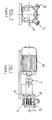
Figure 1 shows in lateral view, a motor-driven pump cutaway in conjuction with the rotation shaft end coupled to the rotor; -
Figure 2 shows a front view of the electric pump inFigure 1 ; -
Figure 3 shows, in enlarged scale, the external end of the rotation shaft foreseen for being engaged with the rotor according to the invention; -
Figure 4 shows the axial section of the rotor according to the invention, foreseen to be coupled on the shaft end inFigure 3 ; and -
Figure 5 shows, in front view, the rotor inFigure 4 ; -
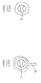
Figure 6 shows another type of shaft section with groove shaped as two trapeziums opposed with one another of a second embodiment; -
Figure 7 shows a central rotor part related to the second embodiment with central hole having a two trapezium form. - With reference to the electric pump shown in
Figure 1 it is indicated by M the drive electric motor and by P the self-priming pump (shown in section view), whose shaft A is driven in rotation by the motor through the joint T. The shaft end A supports the flexible rotor according to the invention that is indicated by G. - The
Figure 2 shows, among other parts, the input coupling E and output coupling U of the pump. - As it is evident in
Figure 3 , the shaft end A has a diametral slot K for being engaged by dry connection with the corresponding element made up of the rotor G, that is shown in more details inFigures 4 and 5 . - Said rotor includes an annular body C provided externally with flexible radial wings R and, according to the invention, a diametral wall or rib D obtained by press-molding together with the body C and wings R.
- Naturally the press-molding operation is single and the used material is an elastomeric material and the like.
- Said rib D forms the rotor element foreseen to be inserted in the slot K of the element A for forming a sure rotation coupling among these parts.
- It is clear that the sizes of the slot K and rib D must be suitable to allow the shaft end and same rib to resist to repeated stresses caused by the shaft A.
- Practical tests in laboratory have shown that optimal values of mechanical resistance and duration are obtained by a rib D having a length slightly lower that the rotor hole dimension F and a thickness (s) substantially equal to the thickness (S) of the annular body C.
- The construction solution of the rotor part foreseen to be engaged with the shaft can vary according to practical requirements. So, for example, instead of using a diametral rib, it can be used two ribs in cross form and also three radial ribs spaced by 120° with one another and, correspond-dingly, the shaft end shall have slots or grooves in cross layout or spaced by 120° with one another.
- Another construction solution is shown in
Figures 6 and 7 , in which theFigure 6 shows another type of shaft section with groove shaped as two trapeziums counterposed with one another owing to a second embodiment, and theFigure 7 shows a central rotor part related to said second embodiment with central hole having the form of two trapeziums. Obviusly this solution has the advantage of a higher rest surface between shaft and rotor that allows to use also greater powers and then to obtain greater flow rates with respect to the ones provided by the connection made by right rib. - In any case the construction solution must not cause the weakening of the shaft end section and/or of the rotor for not reducing its duration, also considering the particular pump running conditions.
Claims (8)
- Rotor made of elastomeric material and the like for self-priming pumps for liquid and dense products made up of an annular body (or hub) provided externally with flexible wings, characterized in that it includes, as integral parts, means for rotation coupling with shaped shaft end (A) driving the pump, which means are obtained press-molding the annular body (C) and flexible radial wings (R).
- Flexible rotor for self-priming pumps according to claim 1, characterrized in that the above mentioned coupling means are made up of a wall or rib (D) crossing diametrally the hole (F) of the same rotor (G) and being engaged with a corresponding groove (K) on the shaft end part (A).
- Flexible rotor for self-priming pumps according to claim 1, characterized in that the wall or diametral rib has a length hardly lower than the hole length (F) of the rotor and a thickness (s) substantially equal to the thickness (S) of the rotor hub (or annular body).
- Flexible rotor for self-priming pumps according to preceding claims, characterized in that it has a shaft section type supplied with groove shaped as two trapeziums counterposed and in that the related central rotor part is supplied with similar rib having a two trapezium form, or saw teeth form or with any other form suitable for increasing the bearing surface of the rotor onto the shaft.
- Flexible rotor for self-priming pumps according to preceding claims, characterized in that the rotor is obtained by a press-molding operation of elastomeric material such as silicone rubbers (for foodstuff and pharmaceutical uses), neoprene (Cr), nitrile (NBR) and the like or the materials well-known with the trade mark name DUTRAL-EPDM (for the use with corrosive acids).
- Flexible rotor for self-priming pumps according to preceding claims, characterized in that the rotor is supplied with diametral rib or with two crossed ribs or further with three radial ribs spaced by 120° and, correspondingly, the shaft end shall have grooves or slots in cross shaping or spaced by 120° angular pitch.
- Flexible rotor for self-priming pumps according to preceding claims, characterized in that the rotor is made up of press-molded materials that can be used in any industrial field such as the chemical, pharmaceutical, cosmetic, foodstuff, oenologic, liquor, gassed drink fields, etc., in particular also with corrosive acids (EPDM) and in contact with foodstuffs (white SILICONE).
- Pump in particular self-priming motor-driven pump for liquid and dense products using the flexible rotor according to one or more of preceding claims.
Applications Claiming Priority (1)
| Application Number | Priority Date | Filing Date | Title |
|---|---|---|---|
| ITMI20071849 ITMI20071849A1 (en) | 2007-09-26 | 2007-09-26 | DIRECT SHAFT TRIMMING SYSTEM FOR FLEXIBLE IMPELLANT TRAINING FOR SELF-PRIMING PUMPS |
Publications (2)
| Publication Number | Publication Date |
|---|---|
| EP2042736A2 true EP2042736A2 (en) | 2009-04-01 |
| EP2042736A3 EP2042736A3 (en) | 2011-08-10 |
Family
ID=40011341
Family Applications (1)
| Application Number | Title | Priority Date | Filing Date |
|---|---|---|---|
| EP08015679A Withdrawn EP2042736A3 (en) | 2007-09-26 | 2008-09-05 | Direct joint system for drive shaft-flexible rotor for self-priming pumps |
Country Status (2)
| Country | Link |
|---|---|
| EP (1) | EP2042736A3 (en) |
| IT (1) | ITMI20071849A1 (en) |
Family Cites Families (3)
| Publication number | Priority date | Publication date | Assignee | Title |
|---|---|---|---|---|
| FR2163935A5 (en) * | 1971-12-07 | 1973-07-27 | Rhone Poulenc Sa | |
| US4592733A (en) * | 1983-12-12 | 1986-06-03 | Outboard Marine Corporation | Water pump for marine propulsion devices |
| IT1216702B (en) * | 1988-03-22 | 1990-03-08 | Bruno Wolfath S R L | Flexible rotor for self-priming pump |
-
2007
- 2007-09-26 IT ITMI20071849 patent/ITMI20071849A1/en unknown
-
2008
- 2008-09-05 EP EP08015679A patent/EP2042736A3/en not_active Withdrawn
Also Published As
| Publication number | Publication date |
|---|---|
| EP2042736A3 (en) | 2011-08-10 |
| ITMI20071849A1 (en) | 2009-03-27 |
Similar Documents
| Publication | Publication Date | Title |
|---|---|---|
| RU2322612C1 (en) | Gear pump with magnetic drive | |
| CN101802411B (en) | Pump rotor for a canned motor pump | |
| US7281896B2 (en) | Fan and impeller thereof | |
| JP2010065528A (en) | Pump | |
| KR20020024590A (en) | Motor-pump unit | |
| TW200706455A (en) | Shaftless propeller | |
| EP1314891A8 (en) | Vacuum pump | |
| US8403656B2 (en) | Vane pump consisting of a two-part stator | |
| US20100054976A1 (en) | Eccentric screw pump | |
| US7033145B2 (en) | Centrifugal pump for electrical household appliance or the like | |
| US7462022B2 (en) | Rotary displacement pump comprising scraper and guide of the scraper | |
| US6674204B1 (en) | Magnet-positioning device for rotor | |
| US20010014252A1 (en) | Coupling means between a thermal motor shaft and a reciprocating pump shaft | |
| CN113056325B (en) | Magnetically Coupled Liquid Mixer | |
| US9719508B2 (en) | Flexible impeller pump | |
| JP4238472B2 (en) | Self-priming pump | |
| US20040219036A1 (en) | Plastic rotor for pumps | |
| ITMI20071849A1 (en) | DIRECT SHAFT TRIMMING SYSTEM FOR FLEXIBLE IMPELLANT TRAINING FOR SELF-PRIMING PUMPS | |
| ATE362060T1 (en) | UNBALANCE COMPENSATION ELEMENT, PUMP AND METHOD FOR BALANCING ELECTRIC MOTOR-DRIVEN PUMPS | |
| MD2128G2 (en) | Multistage centrifugal pump | |
| JP2002005085A (en) | Axial impeller | |
| JP2000297784A (en) | Electric pump shaft for special liquid etc. and method of manufacturing the same | |
| CN203871985U (en) | Pump for conveying fluid | |
| US9145972B2 (en) | Coupling structure | |
| JPS6211348Y2 (en) |
Legal Events
| Date | Code | Title | Description |
|---|---|---|---|
| PUAI | Public reference made under article 153(3) epc to a published international application that has entered the european phase |
Free format text: ORIGINAL CODE: 0009012 |
|
| AK | Designated contracting states |
Kind code of ref document: A2 Designated state(s): AT BE BG CH CY CZ DE DK EE ES FI FR GB GR HR HU IE IS IT LI LT LU LV MC MT NL NO PL PT RO SE SI SK TR |
|
| AX | Request for extension of the european patent |
Extension state: AL BA MK RS |
|
| 17P | Request for examination filed |
Effective date: 20090630 |
|
| PUAL | Search report despatched |
Free format text: ORIGINAL CODE: 0009013 |
|
| AK | Designated contracting states |
Kind code of ref document: A3 Designated state(s): AT BE BG CH CY CZ DE DK EE ES FI FR GB GR HR HU IE IS IT LI LT LU LV MC MT NL NO PL PT RO SE SI SK TR |
|
| AX | Request for extension of the european patent |
Extension state: AL BA MK RS |
|
| RIC1 | Information provided on ipc code assigned before grant |
Ipc: F04C 15/00 20060101ALI20110707BHEP Ipc: F04C 13/00 20060101ALI20110707BHEP Ipc: F04C 5/00 20060101AFI20110707BHEP |
|
| AKX | Designation fees paid |
Designated state(s): AT BE BG CH CY CZ DE DK EE ES FI FR GB GR HR HU IE IS IT LI LT LU LV MC MT NL NO PL PT RO SE SI SK TR |
|
| STAA | Information on the status of an ep patent application or granted ep patent |
Free format text: STATUS: THE APPLICATION IS DEEMED TO BE WITHDRAWN |
|
| 18D | Application deemed to be withdrawn |
Effective date: 20120211 |