EP2042458A2 - Pasper sheet separating apparatus - Google Patents
Pasper sheet separating apparatus Download PDFInfo
- Publication number
- EP2042458A2 EP2042458A2 EP08016263A EP08016263A EP2042458A2 EP 2042458 A2 EP2042458 A2 EP 2042458A2 EP 08016263 A EP08016263 A EP 08016263A EP 08016263 A EP08016263 A EP 08016263A EP 2042458 A2 EP2042458 A2 EP 2042458A2
- Authority
- EP
- European Patent Office
- Prior art keywords
- suction
- paper sheet
- conveying
- paper sheets
- separating apparatus
- Prior art date
- Legal status (The legal status is an assumption and is not a legal conclusion. Google has not performed a legal analysis and makes no representation as to the accuracy of the status listed.)
- Withdrawn
Links
- 230000002093 peripheral effect Effects 0.000 claims description 5
- 238000010521 absorption reaction Methods 0.000 claims 1
- 238000005259 measurement Methods 0.000 description 4
- 238000005452 bending Methods 0.000 description 3
- 239000011435 rock Substances 0.000 description 3
- 230000000694 effects Effects 0.000 description 1
- 230000005611 electricity Effects 0.000 description 1
- 238000004519 manufacturing process Methods 0.000 description 1
- 238000000926 separation method Methods 0.000 description 1
- 230000003068 static effect Effects 0.000 description 1
- 230000000007 visual effect Effects 0.000 description 1
Images





Classifications
-
- B—PERFORMING OPERATIONS; TRANSPORTING
- B65—CONVEYING; PACKING; STORING; HANDLING THIN OR FILAMENTARY MATERIAL
- B65H—HANDLING THIN OR FILAMENTARY MATERIAL, e.g. SHEETS, WEBS, CABLES
- B65H29/00—Delivering or advancing articles from machines; Advancing articles to or into piles
- B65H29/24—Delivering or advancing articles from machines; Advancing articles to or into piles by air blast or suction apparatus
- B65H29/241—Suction devices
- B65H29/242—Suction bands or belts
-
- B—PERFORMING OPERATIONS; TRANSPORTING
- B65—CONVEYING; PACKING; STORING; HANDLING THIN OR FILAMENTARY MATERIAL
- B65H—HANDLING THIN OR FILAMENTARY MATERIAL, e.g. SHEETS, WEBS, CABLES
- B65H29/00—Delivering or advancing articles from machines; Advancing articles to or into piles
- B65H29/58—Article switches or diverters
-
- B—PERFORMING OPERATIONS; TRANSPORTING
- B65—CONVEYING; PACKING; STORING; HANDLING THIN OR FILAMENTARY MATERIAL
- B65H—HANDLING THIN OR FILAMENTARY MATERIAL, e.g. SHEETS, WEBS, CABLES
- B65H2406/00—Means using fluid
- B65H2406/30—Suction means
- B65H2406/32—Suction belts
- B65H2406/323—Overhead suction belt, i.e. holding material against gravity
-
- B—PERFORMING OPERATIONS; TRANSPORTING
- B65—CONVEYING; PACKING; STORING; HANDLING THIN OR FILAMENTARY MATERIAL
- B65H—HANDLING THIN OR FILAMENTARY MATERIAL, e.g. SHEETS, WEBS, CABLES
- B65H2406/00—Means using fluid
- B65H2406/30—Suction means
- B65H2406/36—Means for producing, distributing or controlling suction
-
- B—PERFORMING OPERATIONS; TRANSPORTING
- B65—CONVEYING; PACKING; STORING; HANDLING THIN OR FILAMENTARY MATERIAL
- B65H—HANDLING THIN OR FILAMENTARY MATERIAL, e.g. SHEETS, WEBS, CABLES
- B65H2513/00—Dynamic entities; Timing aspects
- B65H2513/40—Movement
- B65H2513/42—Route, path
-
- B—PERFORMING OPERATIONS; TRANSPORTING
- B65—CONVEYING; PACKING; STORING; HANDLING THIN OR FILAMENTARY MATERIAL
- B65H—HANDLING THIN OR FILAMENTARY MATERIAL, e.g. SHEETS, WEBS, CABLES
- B65H2515/00—Physical entities not provided for in groups B65H2511/00 or B65H2513/00
- B65H2515/30—Forces; Stresses
- B65H2515/34—Pressure, e.g. fluid pressure
Definitions
- the present invention relates to a paper sheet separating apparatus applicable to, for example, an automatic discriminating-jogging imprinter for mail pieces and configured to separate those mail pieces which are unfit for machine-processing.
- An automatic discriminating-jogging imprinter for mail pieces is provided with a hopper section into which various mail pieces are fed.
- the mail pieces in the hopper section are delivered to a discriminating section.
- mail pieces with a predetermined thickness and a predetermined width are discriminated from ones with different thicknesses and widths.
- the mail pieces with the predetermined thickness and width that are discriminated in the discriminating section are transferred to an imprinting section, in which they are imprinted with information. Based on the imprinted information, the discriminated mail pieces are sorted and stored (see Jpn. Pat. Appln. KOKAI Publication No. 2001-253615 , for example).
- the discriminating section cannot discriminate mail pieces with thicknesses smaller than the predetermined thickness, that is, thin non-resilient mail pieces with low bending strength, such as PPC mail pieces, which are unfit for machine-processing. Unless these thin non-resilient mail pieces are removed, however, they inevitably cause jamming, soiling, or breakage.
- the present invention has been made in consideration of these circumferences, and its object is to provide a paper sheet separating apparatus capable of automatically separating even non-resilient paper sheets.
- An apparatus comprises: at least one conveying device composed of a suction roller having a suction hole in a peripheral surface portion thereof and a conveying member which is passed around the suction roller and configured to convey paper sheets by traveling, the conveying member having a suction hole in a surface thereof which communicates with the suction hole of the suction roller; and a negative-pressure producing device which produces a negative pressure on a curved surface of the conveying member curved along the suction roller by drawing air from within the suction roller, the paper sheets which are conveyed by the conveying device being separated based on whether or not the paper sheets are stuck to the curved surface by suction.
- An apparatus comprises: a conveying device composed of a suction roller having a suction hole in a peripheral surface portion thereof and a conveying member which is passed around the suction roller and configured to convey paper sheets by traveling, the conveying member having a suction hole which communicates with the suction hole of the suction roller; a negative-pressure producing device which produces a negative pressure on a curved surface of the conveying member curved along the suction roller by drawing air from within the suction roller; and a pressing device which presses the leading end side of the paper sheet conveyed by the conveying member against the curved surface of the conveying member, the paper sheets which are pressed by the pressing device being separated based on whether or not the paper sheets are stuck to the curved surface of the conveying member by suction.
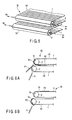
- FIG. 1 is a perspective view showing a paper sheet separating apparatus 1A according to a first embodiment of the invention
- FIG. 2 is a side view of the apparatus 1A
- 1A' denotes a conveying device, which is provided with a conveyor 1, such as a belt, for use as a conveying member that carries paper sheets, such as mail pieces, on its transfer surface 1c and conveys them.
- the unloading side of the conveyor 1 is passed around a driving suction roller 2 and is run as the roller 2 rotates.
- a large number of suction holes 1a are bored through the surface of the conveyor 1.
- Suction holes 2a are bored through a peripheral wall surface portion of the suction roller 2.
- a suction pump 8 for use as a negative-pressure producing device is connected to each of two opposite end surface portions of the suction roller 2 by an air suction pipe 3.
- the conveyor 1 is curved along the suction roller 2.
- a negative pressure is produced on a curved surface 1b of the conveyor 1 as the suction holes 1a of the conveyor 1 communicate with the suction holes 2a of the roller 2.
- a distributor wall 5 is disposed under the unloading side of the conveyor 1.
- the wall 5 serves as a guide device that guides paper sheets conveyed and dropped from the conveyor 1 in first and second directions a and b .
- FIGS. 3A, 3B and 3C show an operation for separating a resilient paper sheet P1 with high bending strength.
- the paper sheet P1 is placed on the transfer surface 1c of the conveyor 1 and conveyed in the manner shown in FIG. 3A .
- the suction pumps 8 are operated to draw out air in the suction roller 2 through the air suction pipes 3.
- a negative pressure is produced on the unloading-side curved surface 1b of the conveyor 1.
- the paper sheet P1 When the paper sheet P1 reaches the side of the curved surface 1b of the conveyor 1, it is drawn in, as shown in FIG. 3B . When this is done, the resilient paper sheet P1 cannot be curvedly deformed along the curved surface 1b of the conveyor 1. Then, the tough paper sheet P1 is dropped from the curved surface 1b of the conveyor 1 by its own weight without failing to maintain its shape, as shown in FIG. 3C . The dropped paper sheet P1 is guided in the first direction a by the distributor wall 5.
- FIGS. 4A, 4B and 4C show an operation for separating a non-resilient paper sheet P2 with low bending strength.
- the paper sheet P2 is placed on the transfer surface 1c of the conveyor 1 and conveyed in the manner shown in FIG. 4A .
- the paper sheet P2 reaches the side of the curved surface 1b of the conveyor 1, as shown in FIG. 4B , it is deformed by suction as it is conveyed along the curved surface 1b.
- the paper sheet P2 is conveyed for a longer distance than the resilient paper sheet P1 is, and ceases to receive a suction force when it passes the distributor wall 5, as shown in FIG. 4C .
- the paper sheet P2 is dropped by its own weight and guided in the second direction b by the distributor wall 5.
- the resilient paper sheet P1 and the non-resilient are separated in this manner.
- FIG. 5 shows a paper sheet separating apparatus 1B according to a second embodiment of the invention.
- the paper sheet separating apparatus 1B of the second embodiment is composed of the aforementioned conveying devices 1A' that are arranged with a predetermined vertical space therebetween.
- resilient paper sheets P1 and non-resilient paper sheets P2 can be separated in the same manner as in the first embodiment described above by means of the lower conveying device 1A'.
- the upper paper sheet P2 is drawn up by the curved surface 1b of the upper conveyor 1, as shown in FIG. 6A .
- the non-resilient paper sheets P2 can be separated above and below by the lower conveying device 1A', as shown in FIG. 6B .
- thin paper sheets can be separated more finely by differentiating the suction pressures of the upper and lower conveying devices 1A'.
- the paper sheets can be separated more delicately in such a manner that thinner ones are stuck to the curved surface 1b of the upper conveyor 1 and conventional thin sheets to the curved surface 1b of the lower conveyor 1.
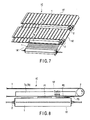
- FIG. 7 shows a paper sheet separating apparatus 1C according to a third embodiment of the invention.
- a plurality of conveying devices 1A' are arranged parallel to one another so as to be spaced upward from and extend at right angles to the aforementioned conveying device 1A'. Further, the conveying devices 1A' on the upper side are provided individually with suction chambers 7a and 7b with different suction forces, which are situated near the suction rollers 2.
- resilient paper sheets P1 and non-resilient paper sheets P2 can be separated in the same manner as in the foregoing first embodiment by means of the lower conveying device 1A'.
- paper sheets P3 that are thinner than the non-resilient paper sheets P2 can be separated after being stuck to the upper conveyor 1 by the suction forces of the suction chambers 7a and 7b of the parallel conveying devices 1A' on the upper side.
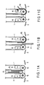
- FIG. 9 shows a paper sheet separating apparatus 1D according to a fourth embodiment of the invention.
- each upright conveying device 1A' is provided with a blow-off chamber 10 that is situated near its suction roller 2.
- a thick paper sheet P1 and a thin paper sheet P2 are placed upright on the floor conveyor belt 9 and conveyed, as shown in FIG. 11A .
- the paper sheets P1 and P2 are separated, as shown in FIG. 11B .
- the thick paper sheet P1 is delivered as it is, while the thin paper sheet P2 is deformed by suction as it is delivered along the curved surface 1b of the conveyor 1.
- the separated thin paper sheet P2 reaches the side of the blow-off chamber 10, it is blown by air from the chamber 10 and separated from the conveyor 1, as shown in FIG. 11C .
- the resilient and non-resilient paper sheets P1 and P2 can be separated in the same manner as in the foregoing first embodiment. Since air is blown against the separated thin paper sheet P2 to force it to be separated from conveyor 1, moreover, the paper sheet P2 cannot be electrostatically attracted to the conveyor 1 even static electricity or the like is generated in suction roller 2.
- the occupied plane area can be made smaller than in the case where the conveying devices 1A' are arranged horizontally.
- FIGS. 12 to 15C show a paper sheet separating apparatus 1E according to a fifth embodiment of the invention.
- the conveyor 1 is provided with a suction chamber 12 that is situated near its suction roller 2.
- first and second distribution gates 16 and 17 that are rockable vertically are arranged below the unloading side of the conveyor 1.
- the distribution gates 16 and 17 guide the paper sheets in the first and second directions a and b by rocking upward. Further, the paper sheets that are guided in the first and second directions a and b are guided by upper guides 18 and 19, respectively.
- first and second distribution gates 16 and 17 are rocked downward, furthermore, they guide the paper sheets in third and fourth directions c and d .
- the paper sheets guided in the third and fourth directions c and d are guided by lower guides 20 and 21, respectively.
- a measuring device 13 is connected to the suction chamber 12, and a drive section 15 is connected to the measuring device 13 through a control section 14.
- the measuring device 13 measures a negative pressure of the suction chamber 12, and the control section 14 controls the drive section 15 based on the measured negative pressure.
- the drive section 15 vertically rocks the first and second distribution gates 16 and 17.
- the control section 14 controls the drive section 15 so as to rock the first and second distribution gates 16 and 17 upward if a high negative pressure is measured. Further, the control section 14 controls the drive section 15 so as to rock the distribution gates 16 and 17 downward if a low negative pressure is measured.
- the negative pressure of the suction chamber 12 is measured by the measuring device 13. If the paper sheet is a large thick one, that is, a resilient paper sheet P1a with a large area, as shown in FIG. 14A , for example, a high negative pressure is measured by the measuring device 13. Based on this measurement, the first and second distribution gates 16 and 17 are rocked upward by the drive section 15. The paper sheet P1a to be unloaded from the conveyor 1 is dropped without being deformed by suction along the curved surface 1b of the conveyor 1. As shown in FIG. 14B , the paper sheet P1a is fed in the first direction a by the first distribution gate 16 and guided along the upper guide 18.
- a large thin paper sheet that is, a non-resilient paper sheet P2a with a large area
- a high negative pressure is also measured by the measuring device 13.
- the first and second distribution gates 16 and 17 are rocked upward by the drive section 15.
- the paper sheet P2a to be unloaded from the conveyor 1 is dropped after being stuck to and conveyed along the curved surface 1b of the conveyor.
- the paper sheet P2a is fed in the second direction b by the second distribution gate 17 and guided along the second guide 19.
- a small thin paper sheet that is, a non-resilient paper sheet P2b with a small area
- a low negative pressure is measured by the measuring device 13.
- the first and second distribution gates 16 and 17 are rocked downward by the drive section 15.
- the paper sheet P2b to be unloaded from the conveyor 1 is dropped after being stuck to and conveyed along the curved surface 1b of the conveyor.
- the paper sheet P2b is fed in the fourth direction d by the second distribution gate 17 and guided along the fourth guide 21.
- a small thick paper sheet that is, a resilient paper sheet P1b with a small area
- a low negative pressure is measured by the measuring device 13.
- the first and second distribution gates 16 and 17 are rocked downward by the drive section 15.
- the resilient paper sheet P1b is dropped along the curved surface 1b of the conveyor 1 without being stuck to it by suction.
- the paper sheet P1b is fed in the third direction c by the first distribution gate 16 and guided along the third guide 20.
- the paper sheets are classified into four types, i.e., the large thick sheets P1a, large thin sheets P2a, small thick sheets P1b, and small thin sheets P2b.
- FIG. 16 shows a paper sheet separating apparatus 1F according to a sixth embodiment of the invention.
- a pressure roller 25 is located over the unloading side of the conveyor 1.
- the roller 25 serves as a pressing device that presses the leading end portion of each paper sheet conveyed by the conveyor 1.
- the pressure roller 25 is rockably mounted on a rocking end portion of rocking lever 26.
- the rocking lever 26 is elastically urged by a spring 27 so that the pressure roller 25 abuts the suction roller 2.
- the position of contact between the rollers 2 and 25 is situated below the transfer surface 1c of the conveyor 1 so that the leading end portion of each paper sheet can be pressed against the curved surface 1b of the conveyor 1.
- a sound-absorbing roller 29 is provided within the suction roller 2.
- the sound-absorbing roller 29 is axially shorter than the suction roller 2 and is contained in the suction roller 2.
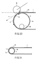
- the resilient and non-resilient paper sheets P1 and P2 can be separated in the same manner as in the foregoing first embodiment. As shown in FIG. 18 , moreover, even a non-resilient paper sheet P4 with its leading end bent away from the curved surface 1b or folded can be separated.
- the pressure roller 25 is not provided, as shown in FIG. 21 , the paper sheet P4 with the deformable leading end portion is conveyed without being stuck to the curved surface 1b of the conveyor 1 by suction, so that it may possibly fail to be separated.
- a resonant sound may sometimes be produced by a whistling effect when air is drawn from within the suction roller 2.
- the sound-absorbing roller 29 rolls within the suction roller 2, thereby preventing the production of the resonant sound.
Landscapes
- Engineering & Computer Science (AREA)
- Mechanical Engineering (AREA)
- Sheets, Magazines, And Separation Thereof (AREA)
- Delivering By Means Of Belts And Rollers (AREA)
Abstract
An apparatus according to the present invention is provided with a suction pump (8) which produces a negative pressure on a curved surface (1b) of a conveyor (1) curved along a suction roller (2) by drawing air from within the suction roller (2). Paper sheets which are conveyed by the conveyor (1) are separated based on whether or not the paper sheets are stuck to the curved surface (1b) by suction.
Description
- The present invention relates to a paper sheet separating apparatus applicable to, for example, an automatic discriminating-jogging imprinter for mail pieces and configured to separate those mail pieces which are unfit for machine-processing.
- An automatic discriminating-jogging imprinter for mail pieces is provided with a hopper section into which various mail pieces are fed. The mail pieces in the hopper section are delivered to a discriminating section. In the discriminating section, mail pieces with a predetermined thickness and a predetermined width are discriminated from ones with different thicknesses and widths. The mail pieces with the predetermined thickness and width that are discriminated in the discriminating section are transferred to an imprinting section, in which they are imprinted with information. Based on the imprinted information, the discriminated mail pieces are sorted and stored (see Jpn. Pat. Appln. KOKAI Publication No.
2001-253615 - In this automatic discriminating-jogging imprinter, the discriminating section cannot discriminate mail pieces with thicknesses smaller than the predetermined thickness, that is, thin non-resilient mail pieces with low bending strength, such as PPC mail pieces, which are unfit for machine-processing. Unless these thin non-resilient mail pieces are removed, however, they inevitably cause jamming, soiling, or breakage.
- Conventionally, therefore, thin non-resilient mail pieces are separated by hand.
- In manually separating thin non-resilient mail pieces, however, they must be instantly discriminated by visual observation. Thus, the discrimination itself is difficult, so that the accuracy and efficiency of separation are poor.
- The present invention has been made in consideration of these circumferences, and its object is to provide a paper sheet separating apparatus capable of automatically separating even non-resilient paper sheets.
- An apparatus according to an aspect of the invention comprises: at least one conveying device composed of a suction roller having a suction hole in a peripheral surface portion thereof and a conveying member which is passed around the suction roller and configured to convey paper sheets by traveling, the conveying member having a suction hole in a surface thereof which communicates with the suction hole of the suction roller; and a negative-pressure producing device which produces a negative pressure on a curved surface of the conveying member curved along the suction roller by drawing air from within the suction roller, the paper sheets which are conveyed by the conveying device being separated based on whether or not the paper sheets are stuck to the curved surface by suction.
- An apparatus according to another aspect of the invention comprises: a conveying device composed of a suction roller having a suction hole in a peripheral surface portion thereof and a conveying member which is passed around the suction roller and configured to convey paper sheets by traveling, the conveying member having a suction hole which communicates with the suction hole of the suction roller; a negative-pressure producing device which produces a negative pressure on a curved surface of the conveying member curved along the suction roller by drawing air from within the suction roller; and a pressing device which presses the leading end side of the paper sheet conveyed by the conveying member against the curved surface of the conveying member, the paper sheets which are pressed by the pressing device being separated based on whether or not the paper sheets are stuck to the curved surface of the conveying member by suction.
- The invention can be more fully understood from the following detailed description when taken in conjunction with the accompanying drawings, in which:
-
FIG. 1 is a perspective view showing a paper sheet separating apparatus according to a first embodiment of the invention; -
FIG. 2 is a side view showing the paper sheet separating apparatus ofFIG. 1 ; -
FIG. 3A is a view showing a paper sheet separating operation by the paper sheet separating apparatus ofFIG. 1 ; -
FIG. 3B is a view showing the paper sheet separating operation by the paper sheet separating apparatus ofFIG. 1 ; -
FIG. 3C is a view showing the paper sheet separating operation by the paper sheet separating apparatus ofFIG. 1 ; -
FIG. 4A is a view showing the paper sheet separating operation by the paper sheet separating apparatus ofFIG. 1 ; -
FIG. 4B is a view showing the paper sheet separating operation by the paper sheet separating apparatus ofFIG. 1 ; -
FIG. 4C is a view showing the paper sheet separating operation by the paper sheet separating apparatus ofFIG. 1 ; -
FIG. 5 is a perspective view showing a paper sheet separating apparatus according to a second embodiment of the invention; -
FIG. 6A is a view showing a paper sheet separating operation by the paper sheet separating apparatus ofFIG. 5 ; -
FIG. 6B is a view showing the paper sheet separating operation by the paper sheet separating apparatus ofFIG. 5 ; -
FIG. 7 is a perspective view showing a paper sheet separating apparatus according to a third embodiment of the invention; -
FIG. 8 is a front view showing the paper sheet separating apparatus ofFIG. 7 ; -
FIG. 9 is a perspective view showing a paper sheet separating apparatus according to a fourth embodiment of the invention; -
FIG. 10 is a plan view showing the paper sheet separating apparatus ofFIG. 9 ; -
FIG. 11A is a view showing a paper sheet separating operation by the paper sheet separating apparatus ofFIG. 9 ; -
FIG. 11B is a view showing the paper sheet separating operation by the paper sheet separating apparatus ofFIG. 9 ; -
FIG. 11C is a view showing the paper sheet separating operation by the paper sheet separating apparatus ofFIG. 9 ; -
FIG. 12 is a perspective view showing a paper sheet separating apparatus according to a fifth embodiment of the invention; -
FIG. 13 is a side view showing the paper sheet separating apparatus ofFIG. 12 ; -
FIG. 14A is a view showing guide directions for paper sheets separated by the paper sheet separating apparatus ofFIG. 12 ; -
FIG. 14B is a view showing a guide direction for a paper sheet separated by the paper sheet separating apparatus ofFIG. 12 ; -
FIG. 15A is a view showing a guide direction for a paper sheet separated by the paper sheet separating apparatus ofFIG. 12 ; -
FIG. 15B is a view showing a guide direction for a paper sheet separated by the paper sheet separating apparatus ofFIG. 12 ; -
FIG. 15C is a view showing a guide direction for a paper sheet separated by the paper sheet separating apparatus ofFIG. 12 ; -
FIG. 16 is a side view showing a paper sheet separating apparatus according to a sixth embodiment of the invention; -
FIG. 17 is an enlarged view showing the paper sheet unloading side of the paper sheet separating apparatus ofFIG. 16 ; -
FIG. 18 is a view showing how a paper sheet with a deformable leading end portion is conveyed by a conveyor ofFIG. 16 ; -
FIG. 19 is a view showing a state in which the deformed leading end portion of the paper sheet conveyed by the conveyor ofFIG. 16 abuts a pressure roller; -
FIG. 20 is a view showing how the deformed leading end portion of the paper sheet abutting the pressure roller ofFIG. 19 is pressed against the curved surface side of the conveyor by the pressure roller; and -
FIG. 21 is a view showing how a paper sheet with a deformable leading end is discharged without the use of the pressure roller. - Embodiments of the present invention will now be described in detail with reference to the accompanying drawings.
-
FIG. 1 is a perspective view showing a papersheet separating apparatus 1A according to a first embodiment of the invention, andFIG. 2 is a side view of theapparatus 1A. InFIG. 1 , 1A' denotes a conveying device, which is provided with aconveyor 1, such as a belt, for use as a conveying member that carries paper sheets, such as mail pieces, on itstransfer surface 1c and conveys them. The unloading side of theconveyor 1 is passed around a drivingsuction roller 2 and is run as theroller 2 rotates. A large number ofsuction holes 1a are bored through the surface of theconveyor 1.Suction holes 2a are bored through a peripheral wall surface portion of thesuction roller 2. Asuction pump 8 for use as a negative-pressure producing device is connected to each of two opposite end surface portions of thesuction roller 2 by anair suction pipe 3. Theconveyor 1 is curved along thesuction roller 2. A negative pressure is produced on acurved surface 1b of theconveyor 1 as the suction holes 1a of theconveyor 1 communicate with the suction holes 2a of theroller 2. - Further, a
distributor wall 5 is disposed under the unloading side of theconveyor 1. Thewall 5 serves as a guide device that guides paper sheets conveyed and dropped from theconveyor 1 in first and second directions a and b. - The following is a description of operations for separating the paper sheets.
-
FIGS. 3A, 3B and 3C show an operation for separating a resilient paper sheet P1 with high bending strength. - The paper sheet P1 is placed on the
transfer surface 1c of theconveyor 1 and conveyed in the manner shown inFIG. 3A . When this is done, the suction pumps 8 are operated to draw out air in thesuction roller 2 through theair suction pipes 3. Thereupon, a negative pressure is produced on the unloading-sidecurved surface 1b of theconveyor 1. - When the paper sheet P1 reaches the side of the
curved surface 1b of theconveyor 1, it is drawn in, as shown inFIG. 3B . When this is done, the resilient paper sheet P1 cannot be curvedly deformed along thecurved surface 1b of theconveyor 1. Then, the tough paper sheet P1 is dropped from thecurved surface 1b of theconveyor 1 by its own weight without failing to maintain its shape, as shown inFIG. 3C . The dropped paper sheet P1 is guided in the first direction a by thedistributor wall 5. -
FIGS. 4A, 4B and 4C show an operation for separating a non-resilient paper sheet P2 with low bending strength. - The paper sheet P2 is placed on the
transfer surface 1c of theconveyor 1 and conveyed in the manner shown inFIG. 4A . When the paper sheet P2 reaches the side of thecurved surface 1b of theconveyor 1, as shown inFIG. 4B , it is deformed by suction as it is conveyed along thecurved surface 1b. The paper sheet P2 is conveyed for a longer distance than the resilient paper sheet P1 is, and ceases to receive a suction force when it passes thedistributor wall 5, as shown inFIG. 4C . Thereupon, the paper sheet P2 is dropped by its own weight and guided in the second direction b by thedistributor wall 5. The resilient paper sheet P1 and the non-resilient are separated in this manner. -
FIG. 5 shows a papersheet separating apparatus 1B according to a second embodiment of the invention. - Like numbers are used to designate like portions of the first and second embodiments and a detailed description thereof is omitted.
- The paper
sheet separating apparatus 1B of the second embodiment is composed of the aforementioned conveyingdevices 1A' that are arranged with a predetermined vertical space therebetween. - According to this second embodiment, resilient paper sheets P1 and non-resilient paper sheets P2 can be separated in the same manner as in the first embodiment described above by means of the lower conveying
device 1A'. - If two adjacent non-resilient paper sheets P2 overlap each other as they are conveyed, according to the second embodiment, moreover, the upper paper sheet P2 is drawn up by the
curved surface 1b of theupper conveyor 1, as shown inFIG. 6A . Thus, the non-resilient paper sheets P2 can be separated above and below by the lower conveyingdevice 1A', as shown inFIG. 6B . - According to the second embodiment, furthermore, thin paper sheets can be separated more finely by differentiating the suction pressures of the upper and lower conveying
devices 1A'. For example, the paper sheets can be separated more delicately in such a manner that thinner ones are stuck to thecurved surface 1b of theupper conveyor 1 and conventional thin sheets to thecurved surface 1b of thelower conveyor 1. -
FIG. 7 shows a papersheet separating apparatus 1C according to a third embodiment of the invention. - Like numbers are used to designate like portions of the first and third embodiments and a detailed description thereof is omitted.
- In the paper
sheet separating apparatus 1C of this third embodiment, a plurality of conveyingdevices 1A' are arranged parallel to one another so as to be spaced upward from and extend at right angles to the aforementioned conveyingdevice 1A'. Further, the conveyingdevices 1A' on the upper side are provided individually withsuction chambers suction rollers 2. - According to this third embodiment, resilient paper sheets P1 and non-resilient paper sheets P2 can be separated in the same manner as in the foregoing first embodiment by means of the lower conveying
device 1A'. As shown inFIG. 8 , moreover, paper sheets P3 that are thinner than the non-resilient paper sheets P2 can be separated after being stuck to theupper conveyor 1 by the suction forces of thesuction chambers devices 1A' on the upper side. -
FIG. 9 shows a papersheet separating apparatus 1D according to a fourth embodiment of the invention. - Like numbers are used to designate like portions of the first and fourth embodiments and a detailed description thereof is omitted.
- In this fourth embodiment, the conveying
devices 1A' shown inFIG. 1 are arranged upright and parallel to each other with a predetermined space therebetween, and a floor conveyor belt 9 is provided between the respective lower end portions of the conveyingdevices 1A'. As also shown inFIG. 10 , moreover, each upright conveyingdevice 1A' is provided with a blow-off chamber 10 that is situated near itssuction roller 2. - As shown in
FIG. 11A , a thick paper sheet P1 and a thin paper sheet P2 are placed upright on the floor conveyor belt 9 and conveyed, as shown inFIG. 11A . When they reach the unloading side, the paper sheets P1 and P2 are separated, as shown inFIG. 11B . More specifically, the thick paper sheet P1 is delivered as it is, while the thin paper sheet P2 is deformed by suction as it is delivered along thecurved surface 1b of theconveyor 1. When the separated thin paper sheet P2 reaches the side of the blow-off chamber 10, it is blown by air from thechamber 10 and separated from theconveyor 1, as shown inFIG. 11C . - According to this fourth embodiment, the resilient and non-resilient paper sheets P1 and P2 can be separated in the same manner as in the foregoing first embodiment. Since air is blown against the separated thin paper sheet P2 to force it to be separated from
conveyor 1, moreover, the paper sheet P2 cannot be electrostatically attracted to theconveyor 1 even static electricity or the like is generated insuction roller 2. - Since the conveying
devices 1A' are arranged upright and parallel to each other, the occupied plane area can be made smaller than in the case where the conveyingdevices 1A' are arranged horizontally. -
FIGS. 12 to 15C show a papersheet separating apparatus 1E according to a fifth embodiment of the invention. - Like numbers are used to designate like portions of the first and fifth embodiments and a detailed description thereof is omitted.
- In this fifth embodiment, the
conveyor 1 is provided with asuction chamber 12 that is situated near itssuction roller 2. - As shown in
FIG. 14A , moreover, first andsecond distribution gates conveyor 1. Thedistribution gates upper guides - As the first and
second distribution gates lower guides - As shown in
FIG. 13 , on the other hand, a measuringdevice 13 is connected to thesuction chamber 12, and adrive section 15 is connected to the measuringdevice 13 through acontrol section 14. The measuringdevice 13 measures a negative pressure of thesuction chamber 12, and thecontrol section 14 controls thedrive section 15 based on the measured negative pressure. Thedrive section 15 vertically rocks the first andsecond distribution gates - The
control section 14 controls thedrive section 15 so as to rock the first andsecond distribution gates control section 14 controls thedrive section 15 so as to rock thedistribution gates - When a paper sheet is conveyed by the
conveyor 1 and reaches the side of thesuction chamber 12, in the arrangement described above, the negative pressure of thesuction chamber 12 is measured by the measuringdevice 13. If the paper sheet is a large thick one, that is, a resilient paper sheet P1a with a large area, as shown inFIG. 14A , for example, a high negative pressure is measured by the measuringdevice 13. Based on this measurement, the first andsecond distribution gates drive section 15. The paper sheet P1a to be unloaded from theconveyor 1 is dropped without being deformed by suction along thecurved surface 1b of theconveyor 1. As shown inFIG. 14B , the paper sheet P1a is fed in the first direction a by thefirst distribution gate 16 and guided along theupper guide 18. - When a large thin paper sheet, that is, a non-resilient paper sheet P2a with a large area, reaches the side of the
suction chamber 12, as shown inFIG. 14B , moreover, a high negative pressure is also measured by the measuringdevice 13. Based on this measurement, the first andsecond distribution gates drive section 15. The paper sheet P2a to be unloaded from theconveyor 1 is dropped after being stuck to and conveyed along thecurved surface 1b of the conveyor. As shown inFIG. 15A , the paper sheet P2a is fed in the second direction b by thesecond distribution gate 17 and guided along thesecond guide 19. - When a small thin paper sheet, that is, a non-resilient paper sheet P2b with a small area, reaches the side of the
suction chamber 12, as shown inFIG. 15A , moreover, a low negative pressure is measured by the measuringdevice 13. Based on this measurement, the first andsecond distribution gates drive section 15. The paper sheet P2b to be unloaded from theconveyor 1 is dropped after being stuck to and conveyed along thecurved surface 1b of the conveyor. As shown inFIG. 15B , the paper sheet P2b is fed in the fourth direction d by thesecond distribution gate 17 and guided along thefourth guide 21. - When a small thick paper sheet, that is, a resilient paper sheet P1b with a small area, reaches the side of the
suction chamber 12, as shown inFIG. 15B , furthermore, a low negative pressure is measured by the measuringdevice 13. Based on this measurement, the first andsecond distribution gates drive section 15. The resilient paper sheet P1b is dropped along thecurved surface 1b of theconveyor 1 without being stuck to it by suction. As shown inFIG. 15C , the paper sheet P1b is fed in the third direction c by thefirst distribution gate 16 and guided along thethird guide 20. - Thus, the paper sheets are classified into four types, i.e., the large thick sheets P1a, large thin sheets P2a, small thick sheets P1b, and small thin sheets P2b.
-
FIG. 16 shows a papersheet separating apparatus 1F according to a sixth embodiment of the invention. - Like numbers are used to designate like portions of the first and sixth embodiments and a detailed description thereof is omitted.
- In this sixth embodiment, a
pressure roller 25 is located over the unloading side of theconveyor 1. Theroller 25 serves as a pressing device that presses the leading end portion of each paper sheet conveyed by theconveyor 1. Thepressure roller 25 is rockably mounted on a rocking end portion of rockinglever 26. The rockinglever 26 is elastically urged by aspring 27 so that thepressure roller 25 abuts thesuction roller 2. As shown inFIG. 17 , the position of contact between therollers transfer surface 1c of theconveyor 1 so that the leading end portion of each paper sheet can be pressed against thecurved surface 1b of theconveyor 1. - Further, a sound-absorbing
roller 29 is provided within thesuction roller 2. The sound-absorbingroller 29 is axially shorter than thesuction roller 2 and is contained in thesuction roller 2. - According to this sixth embodiment, as in the foregoing first embodiment, the resilient and non-resilient paper sheets P1 and P2 can be separated in the same manner as in the foregoing first embodiment. As shown in
FIG. 18 , moreover, even a non-resilient paper sheet P4 with its leading end bent away from thecurved surface 1b or folded can be separated. - Specifically, when the paper sheet P4 is conveyed to the unloading side by the
conveyor 1 so that its deformed leading end portion abuts thepressure roller 25, as shown inFIG. 19 , it is caught and swallowed as thepressure roller 25 rotates, as shown inFIG. 20 . Thereupon, the paper sheet P4 is stuck to thecurved surface 1b ofconveyor 1 by suction as it is conveyed in the direction of arrow b, and is then separated. - If the
pressure roller 25 is not provided, as shown inFIG. 21 , the paper sheet P4 with the deformable leading end portion is conveyed without being stuck to thecurved surface 1b of theconveyor 1 by suction, so that it may possibly fail to be separated. - Further, a resonant sound may sometimes be produced by a whistling effect when air is drawn from within the
suction roller 2. In such a case, the sound-absorbingroller 29 rolls within thesuction roller 2, thereby preventing the production of the resonant sound.
Claims (11)
- A paper sheet separating apparatus characterized by comprising:at least one conveying device (1A') composed of a suction roller (2) having a suction hole (2a) in a peripheral surface portion thereof and a conveying member (1) which is passed around the suction roller (2) and configured to convey paper sheets by traveling, the conveying member (1) having a suction hole (1a) in a surface thereof which communicates with the suction hole (2a) of the suction roller (2); anda negative-pressure producing device (8) which produces a negative pressure on a curved surface (1b) of the conveying member (1) curved along the suction roller (2) by drawing air from within the suction roller (2),the paper sheets which are conveyed by the conveying member (1) being separated based on whether or not the paper sheets are stuck to the curved surface (1b) by suction.
- A paper sheet separating apparatus according to claim 1, characterized by further comprising a guide device (5) which guides the separated paper sheets in a first direction and a second direction different from the first direction.
- A paper sheet separating apparatus according to claim 1, characterized in that the conveying devices (1A') are arranged opposite each other with a predetermined vertical space therebetween, and the paper sheets are separated based on whether or not the paper sheets are stuck to the curved surfaces (1b) of the respective conveying members (1) of the upper and lower conveying devices (1A') by suction.
- A paper sheet separating apparatus according to claim 1, characterized in that the conveying devices (1A') are arranged across and opposite each other with a predetermined vertical space therebetween, the upper conveying device (1A') is provided with a suction chamber (7a), and the paper sheets with thicknesses smaller than a predetermined thickness, among other paper sheets conveyed by the lower conveying device (1A'), are stuck to the surface of the conveying member (1) of the upper conveying device (1A') by a suction force of the suction chamber (7a) as the thin paper sheets are conveyed.
- A paper sheet separating apparatus according to claim 1, characterized in that the conveying devices (1A') are arranged upright and opposite each other with a predetermined space therebetween, a floor conveying device (9) for conveying the paper sheets is provided between the respective lower end portions of the conveying devices (1A'), and the conveying devices (1A') are provided with blow-off chambers (10), individually, such that air from the blow-off chambers (10) is blown against those paper sheets which are stuck to the curved surfaces (1b) of the respective conveying members (1) of the conveying devices (1A') by suction and are to be separated and conveyed, among other paper sheets conveyed by the floor conveyor device (9), whereby the stuck paper sheets are separated from the surface of the conveying member (1).
- A paper sheet separating apparatus according to claim 1, characterized by further comprising a suction chamber (12) which is disposed in the conveying device (1A') and produces a negative pressure on the surface of the conveying member (1) of the conveying device (1A'), a measuring device (13) which measures the negative pressure in the suction chamber (12), and a distribution gate (16, 17) which is operated based on the negative pressure measured by the measuring device (13) and guides the paper sheets, which are separated based on whether or not the paper sheets are stuck to the curved surface (1b) of the conveying member (1) by suction, in different directions depending on the sizes of the paper sheets.
- A paper sheet separating apparatus characterized by comprising:a conveying device (1A') composed of a suction roller (2) having a suction hole (2a) in a peripheral surface portion thereof and a conveying member (1) which is passed around the suction roller (2) and configured to convey paper sheets by traveling, the conveying member (1) having a suction hole (1a) which communicates with the suction hole (2a) of the suction roller (2);a negative-pressure producing device (8) which produces a negative pressure on a curved surface (1b) of the conveying member (1) curved along the suction roller (2) by drawing air from within the suction roller (2); anda pressing device (25) which presses the leading end side of the paper sheet conveyed by the conveying member (1) against the curved surface (1b) of the conveying member (1),the paper sheets which are pressed by the pressing device (25) being separated based on whether or not the paper sheets are stuck to the curved surface (1b) of the conveying member (1) by suction.
- A paper sheet separating apparatus according to claim 7, characterized in that the pressing device is a pressure roller (25) which abuts the curved surface (1b) of the conveying member (1).
- A paper sheet separating apparatus according to claim 7, characterized in that the suction roller (2) contains therein a sound-absorbing roller (29) having sound absorption properties.
- A paper sheet separating apparatus according to claim 8, characterized in that the position where the pressure roller (25) abuts the curved surface of the conveying member (1) is situated below a transfer surface (1c) of the conveying member (1).
- A paper sheet separating apparatus according to claim 8, characterized in that the pressure roller (25) is movable toward or away from the curved surface (1b) of the conveying member (1) and is elastically urged toward the curved surface (1b) of the conveying member (1).
Applications Claiming Priority (2)
| Application Number | Priority Date | Filing Date | Title |
|---|---|---|---|
| JP2007255957 | 2007-09-28 | ||
| JP2008129236A JP2009096639A (en) | 2007-09-28 | 2008-05-16 | Paper sheet separator |
Publications (1)
| Publication Number | Publication Date |
|---|---|
| EP2042458A2 true EP2042458A2 (en) | 2009-04-01 |
Family
ID=40139184
Family Applications (1)
| Application Number | Title | Priority Date | Filing Date |
|---|---|---|---|
| EP08016263A Withdrawn EP2042458A2 (en) | 2007-09-28 | 2008-09-16 | Pasper sheet separating apparatus |
Country Status (2)
| Country | Link |
|---|---|
| US (1) | US20090084715A1 (en) |
| EP (1) | EP2042458A2 (en) |
Cited By (2)
| Publication number | Priority date | Publication date | Assignee | Title |
|---|---|---|---|---|
| WO2011085975A1 (en) * | 2010-01-13 | 2011-07-21 | Giesecke & Devrient Gmbh | Transport system for sheet material |
| EP3763646A1 (en) * | 2019-07-11 | 2021-01-13 | Müller Apparatebau GmbH | Device and method for transferring sheets between conveyor units |
Families Citing this family (1)
| Publication number | Priority date | Publication date | Assignee | Title |
|---|---|---|---|---|
| US9908734B2 (en) * | 2014-08-26 | 2018-03-06 | Océ-Technologies B.V. | Printing system comprising a sheet separation system |
Family Cites Families (6)
| Publication number | Priority date | Publication date | Assignee | Title |
|---|---|---|---|---|
| DK112101B (en) * | 1967-06-12 | 1968-11-11 | J Carstens | Sheet conveyor. |
| DE2856777C2 (en) * | 1978-12-29 | 1980-11-13 | Gao Gesellschaft Fuer Automation Und Organisation Mbh, 8000 Muenchen | Stacking device for flat goods |
| JP3320852B2 (en) * | 1993-08-02 | 2002-09-03 | 株式会社名南製作所 | Sheet-like article sorting device |
| US6092804A (en) * | 1997-10-17 | 2000-07-25 | Heidelberger Druckmaschinen Ag | Apparatus for preventing jams in a folder of a printing press |
| US6494452B1 (en) * | 2000-10-19 | 2002-12-17 | Krzysztof Karasiewicz | Method and apparatus to decelerate printed product in a stacking process |
| FI118017B (en) * | 2004-03-11 | 2007-05-31 | Metso Paper Inc | Suppressor belt conveyor for inserting a conveyor belt into a forming machine |
-
2008
- 2008-09-15 US US12/210,574 patent/US20090084715A1/en not_active Abandoned
- 2008-09-16 EP EP08016263A patent/EP2042458A2/en not_active Withdrawn
Cited By (5)
| Publication number | Priority date | Publication date | Assignee | Title |
|---|---|---|---|---|
| WO2011085975A1 (en) * | 2010-01-13 | 2011-07-21 | Giesecke & Devrient Gmbh | Transport system for sheet material |
| CN102781799A (en) * | 2010-01-13 | 2012-11-14 | 德国捷德有限公司 | Transport system for sheet material |
| RU2496702C2 (en) * | 2010-01-13 | 2013-10-27 | Гизеке Унд Девриент Гмбх | Sheet material conveying system |
| US9027741B2 (en) | 2010-01-13 | 2015-05-12 | Giesecke & Devrient Gmbh | Transport system for sheet material |
| EP3763646A1 (en) * | 2019-07-11 | 2021-01-13 | Müller Apparatebau GmbH | Device and method for transferring sheets between conveyor units |
Also Published As
| Publication number | Publication date |
|---|---|
| US20090084715A1 (en) | 2009-04-02 |
Similar Documents
| Publication | Publication Date | Title |
|---|---|---|
| JP5330519B2 (en) | Bundle state detection system and separation / extraction device | |
| EP2110352A1 (en) | Paper money feeder | |
| WO2012170267A2 (en) | Sorting by controlling scanned document velocity | |
| KR100866290B1 (en) | Medium handling device | |
| US20090084715A1 (en) | Paper sheet separating apparatus | |
| CN106062832A (en) | Bank notes handling apparatus | |
| EP1543880B1 (en) | Shredder for sheets | |
| KR20090032973A (en) | Paper sheet separator | |
| CN203512838U (en) | Paper class taking-out device | |
| EP2843631B1 (en) | Sheet discriminating device and sheet processing apparatus | |
| EP2497728A2 (en) | Paper sheet take-out apparatus | |
| EP2141099A3 (en) | Paper sheet feeding device | |
| JP4760629B2 (en) | Paper sheet handling equipment | |
| KR100990113B1 (en) | Banknote Insert of Banknote Counter | |
| CN111524267B (en) | Cash inspecting device | |
| KR100457267B1 (en) | Apparatus for paying out a sheet body | |
| JP3943969B2 (en) | Paper sheet separation and discharge device | |
| JP2009007133A (en) | Paper sheet stacking device | |
| JP2008084170A (en) | Paper sheet processing apparatus and impeller stacking apparatus used therefor | |
| JP4326441B2 (en) | Banknote handling equipment | |
| JP6101383B2 (en) | Paper sheet take-in device | |
| JP2012076875A (en) | Papers take-in apparatus | |
| JP3656108B2 (en) | Paper sheet separator | |
| JP4594827B2 (en) | Paper sheet take-out device | |
| JP3980982B2 (en) | Paper sheet processing equipment |
Legal Events
| Date | Code | Title | Description |
|---|---|---|---|
| PUAI | Public reference made under article 153(3) epc to a published international application that has entered the european phase |
Free format text: ORIGINAL CODE: 0009012 |
|
| 17P | Request for examination filed |
Effective date: 20080916 |
|
| AK | Designated contracting states |
Kind code of ref document: A2 Designated state(s): AT BE BG CH CY CZ DE DK EE ES FI FR GB GR HR HU IE IS IT LI LT LU LV MC MT NL NO PL PT RO SE SI SK TR |
|
| AX | Request for extension of the european patent |
Extension state: AL BA MK RS |
|
| STAA | Information on the status of an ep patent application or granted ep patent |
Free format text: STATUS: THE APPLICATION HAS BEEN WITHDRAWN |
|
| 18W | Application withdrawn |
Effective date: 20100819 |