EP2042277B1 - Flexible gripping tool - Google Patents
Flexible gripping tool Download PDFInfo
- Publication number
- EP2042277B1 EP2042277B1 EP08016615A EP08016615A EP2042277B1 EP 2042277 B1 EP2042277 B1 EP 2042277B1 EP 08016615 A EP08016615 A EP 08016615A EP 08016615 A EP08016615 A EP 08016615A EP 2042277 B1 EP2042277 B1 EP 2042277B1
- Authority
- EP
- European Patent Office
- Prior art keywords
- gripping tool
- frame
- gripper
- gripping
- workpieces
- Prior art date
- Legal status (The legal status is an assumption and is not a legal conclusion. Google has not performed a legal analysis and makes no representation as to the accuracy of the status listed.)
- Not-in-force
Links
Images


Classifications
-
- B—PERFORMING OPERATIONS; TRANSPORTING
- B25—HAND TOOLS; PORTABLE POWER-DRIVEN TOOLS; MANIPULATORS
- B25J—MANIPULATORS; CHAMBERS PROVIDED WITH MANIPULATION DEVICES
- B25J15/00—Gripping heads and other end effectors
- B25J15/0052—Gripping heads and other end effectors multiple gripper units or multiple end effectors
- B25J15/0061—Gripping heads and other end effectors multiple gripper units or multiple end effectors mounted on a modular gripping structure
-
- B—PERFORMING OPERATIONS; TRANSPORTING
- B27—WORKING OR PRESERVING WOOD OR SIMILAR MATERIAL; NAILING OR STAPLING MACHINES IN GENERAL
- B27M—WORKING OF WOOD NOT PROVIDED FOR IN SUBCLASSES B27B - B27L; MANUFACTURE OF SPECIFIC WOODEN ARTICLES
- B27M1/00—Working of wood not provided for in subclasses B27B - B27L, e.g. by stretching
- B27M1/08—Working of wood not provided for in subclasses B27B - B27L, e.g. by stretching by multi-step processes
Definitions
- the invention relates to a gripping tool for one or more workpieces.
- robotic gripping tools are known in various embodiments. They have a rigid frame, which can be connected via a port with the hand of a robot or other manipulator. On the frame several grippers are attached.
- the previously known gripping tools are adapted by their rigid design to certain workpieces.
- a gripping tool with a rigid gripper frame known which consists of several mutually firmly connected rods with it also fixedly arranged suckers.
- the gripper frame has a separating device for the top sheet, wherein at a frame corner a single sucker is arranged on a pivot arm and can be swung up a small piece together with the sucked corner region of a sheet. As a result, a small injection slot is formed on the sheet corner, can be injected into the compressed air. The uppermost sheet is lifted off the stack while maintaining its flatness with the rigid gripper frame, whereby the injected compressed air ensures the sheet metal separation.
- the DE 10 2005 062 706 A1 teaches a device for direct-frictional gripping of geometrically variant objects with robots and handling devices.
- the frame is made of a one-piece rigid Base plate, are arranged on the cylinder drives with suckers on the piston rod ends movable. Due to the drive adjustment and the extension movement of the cylinders, the suction cups are adjustable in their spatial position and can be adapted to a curved workpiece geometry.
- the WO 2006/089327 A1 is concerned with a gripping device, which shows a rigid connection plate with pivotally arranged at the plate corners supporting arms.
- the support arms are fixed in their pivotal position by means of a stop and locking device.
- suckers are arranged at the ends of the support arms.
- the support arms can be linearly adjustable in their longitudinal direction.
- EP 1 396 313 A1 is a rigid gripper frame with several suckers known, which are linear in height and partly also laterally adjustable linearly and the suction cups are arranged hingedly at the end of a vertical feed unit.
- the invention solves this problem with a gripping tool according to claim 1 and a method according to claim 15.
- the multi-unit frame has the advantage that it can adapt to different workpiece geometries. This is particularly favorable if the workpieces tend to change shape or in stack form. Within a stack, workpieces can be deformed by external displacement, a skewed or skewed stack shape or the like. In addition, the claimed gripping tool is also suitable for handling different workpieces. Due to the preferably controllable adjusting device, the multi-unit frame in the respectively desired or required shape.
- the adjustable gripping tool can also fulfill additional functions in the handling of the workpieces.
- the shaping of the workpiece can be changed by an adjustment of the frame, wherein an initially curved workpiece, e.g. can be stretched. A reverse deformation is possible.
- a separation or a peeling effect can take place by changing the frame geometry, taking along the gripped workpiece. This facilitates the gripping of workpieces from a stack.
- the grippers connected to the movable frame members can follow the changes in shape of the multi-unit frame and also adapt to the changed geometry.
- the grippers may have one or more axes of movement. This offers an additional possibility of adaptation of the gripping tool to the workpiece or stack geometry.
- the claimed gripping tool can be used for a wide variety of purposes and workpieces. Its flexibility offers high operational and functional safety. In addition, the adjustments can be carried out very quickly, which benefits the cycle time and cost-effectiveness of the flexible gripping tool in industrial use.
- the grippers can be designed and arranged in any suitable manner. Particularly favorable is an arrangement at the connection points of the frame members. As a result, the grippers can follow the changes in geometry of the frame and in particular a rounding formed thereby.
- Reset elements hold the grippers in a central position or on an angle bisecting the adjacent ones Frame members and provide in the case of relief for the provision in a starting position. It is advantageous if the grippers are mounted coaxially with the adjacent frame members pivotally. Adjustments of the grippers to the workpiece and stack geometry can be ensured via one or more further rotary and / or translatory axes.
- Other restoring elements which may be formed as gas springs, for example, provide for defined starting positions in a rest and relief position.
- a gimbal bearing of the gripper is particularly favorable.
- a sliding bearing allows tracking of the gripper in bends and elongations of the workpieces and the multi-unit frame.
- the adjusting device can be designed in any suitable manner. In particular, it may be e.g. have a remotely controllable actuator with one or more actuators.
- the claimed crank mechanism has the advantage that several frame members can be actuated with one drive. By choosing a suitable crank geometry, the mutual adjustments and angular positions of the frame members can be influenced and adjusted in the desired manner. In particular, uniform symmetry movements can be achieved by means of a symmetrical crank drive, the frame being provided with the grippers, e.g. a circular contour or one of the circular shape in any way different curved contour can take. By varying the number of frame members smaller or larger gripping tools can be created with correspondingly variable adjustment.
- the flexible gripping tool can form together with a manipulator a handling device that can be used for any purpose and in any industry.
- An advantageous application is included Stacking devices with which workpiece stack can be assembled and disassembled, which can be taken into account depending on the stack height, workpiece geometry or other reasons variable stack shape. Also possible changes in shape due to intermediate layers, workpiece distortions or other reasons can be compensated without affecting the stacker function. Further areas of application are the handling of bowled or other workpieces with round or other shapes.
- vehicle construction is also an advantageous use, for example, when feeding and accurate pressing of body parts, such as roof panels, other curved or otherwise linear or non-linearly shaped other vehicle parts, such as side walls.
- the flexible gripping tool can be adapted with the held body part to the possibly tolerant or otherwise changeable shape of the other vehicle parts and ensure uniform contact pressure and conditioning of the entrained workpiece.
- the flexible gripping tool may be combined with one or more entrained or external measuring devices to detect and utilize workpiece properties, such as the actual shape of the workpieces, their surface finish, the moisture of wood workpieces or the like, for the control of the gripping tool and the handling device.
- workpieces can be gripped in misplaced positions by means of a spatially oversized gripping tool, whereby the incorrect position is also detected by one or more axes.
- the misalignment can be compensated again by a corresponding movement correction of the manipulator and the workpiece can be delivered in the correct desired position.
- These position corrections can be carried out very quickly and during the handling operation.
- the handling device thereby has a very high gripping and positional accuracy and a large handling capacity.
- One or more handling devices may be located in a handling station and cooperate in a coordinated manner.
- a preferred area of use is the restacking of workpieces to form intermediate stacks of different workpieces or workpieces and inserts. Conversely, such an intermediate stack can be unstacked again and sorted back, whereby a sorted stack of workpieces can be formed.
- the gripping tool can record several workpieces at the same time or one after another and put them down again, whereby the picking and storage order can be changed as desired. This allows sorting of workpieces and allows the formation and modification of any stack shapes. Workpieces can also be picked up without a stack, transported, possibly changed in their position and orientation and immediately stored again.
- the handling processes are arbitrary.
- a particularly suitable use is in the handling of wood parts, e.g. Boards or panels, which are to be supplied in a wet state on a feed stack and to be stacked for subsequent drying in a mixing stack with the insertion of dry metal sheets. After drying, the mixed stack can be rearranged again, the dried wood parts are stacked into a discard pile and the dryers are buffered or reused directly to form a new intermediate stack with wet wood parts.
- wood parts e.g. Boards or panels
- the invention relates to a gripping device (1) which is suitable and intended for tool-like handling by means of a handling device (2) and which is referred to below as gripping tool.
- the invention further relates to a handling device (2) equipped with the gripping tool (1) and also to a handling station (7) equipped with one or more handling devices (2).
- the invention is also concerned with a method of handling workpieces (8).
- the gripping tool (1) is used for gripping and handling of one or more workpieces (8), which may be of any desired design.
- substantially planar and relatively thin workpieces are shown in sheet form. This can e.g. Planks, panels, plates or the like of wood, metal, plastic or other materials.
- the workpieces (8) may also have a different shape and e.g. as singly or multiply curved parts, e.g. Tubes, tubs or the like. Be formed.
- the workpieces (8) may be any other shapes, e.g. have stepped or rugged shapes or the like.
- the gripper tool (1) is flexible and adjustable and can change its geometry controllable. It consists in the various embodiments of each one multi-membered frame (13) whose frame members (15,16,17) are hinged together.
- the gripping tool (1) also has at least one controllable adjusting device (24) for the mutual adjustment of more than two frame members (15, 16, 17).
- the frame members (15, 16, 17) are arranged in a row one behind the other and are connected to one another at the connection points (21) by bearings (22), preferably pivot bearings.
- the frame members (15,16,17) can rotate against each other and assume any shape in the course of the link chain. This can be eg the in FIGS. 12 to 14 and 18 to 19 be shown concave trough shape.
- the in FIG. 21 illustrated convex arch shape possible.
- Such curvatures or curves in the frame shape may also be present only partially, with a straight shape or a counter-curved shape being present in the other regions.
- the frame (13) may also have a plurality of rows of frame members (15, 16, 17) next to one another.
- the frame members (15, 16, 17) can in this case also be connected to one another transversely and arranged in a grid pattern.
- the number of frame members (15,16,17) can be arbitrarily large and is at least two.
- the number of links can be even or odd.
- With an odd number of links there is a central frame member (15) and on both sides subsequent side frame members (16).
- To the Rack ends are each two end frame members (17) available.
- the frame members (15,16,17) may have a same or different shape. Furthermore, their shape characteristics may be similar and differ, for example, in the length of the limbs.
- the central members (15) and the intermediate members (16) are formed substantially similar, wherein the end members (17) have a different and shortened shape.
- the frame members (15, 16, 17) can be, for example, bridge-like or bow-shaped.
- FIG. 8 and 9 show constructive design options.
- the central and intermediate links (15,16) each consist of a longitudinal axis extending in the frame member (18), on the end of each two obliquely outwardly projecting side parts (19) are connected. At the ends there are the connection points (21) and the said pivot bearing (22).
- the central parts (18) may for example consist of a plate or, as in the embodiments shown, two or more parallel arms, which are cross-connected with each other by webs.
- the side parts (19) may be fork-shaped and multi-armed, for example, two-armed, be formed.
- the end members (17) may each have a side part (19), which may have two or more bearing arms, which are connected by a web portion (20) to form a bow.
- the web part (20) may also have a longitudinal extension which may be similar to the middle parts (18) of the other frame members (15, 16). Notwithstanding the embodiments shown, the frame members (15,16,17) may have any other suitable shape.
- the frame (13) has at a suitable point at least one connection (12) for connection to a manipulator (3,4,5).
- the terminal (12) may be e.g. a flange plate for fixed or detachable connection with the output flange of a manipulator hand (6).
- the connection (12) can also be designed as part of an exchangeable coupling.
- the connection (12) is preferably arranged centrally on the frame (13) and in particular on the middle part (18) of its central member (15) in the embodiments shown.
- the port (12) may alternatively be off-center and e.g. be arranged on an intermediate member (16). It is also a multiple arrangement of terminals (12) possible.
- the adjusting device (24) can be present once or several times. It may be designed constructively in any suitable manner and is preferably controllable. It consists of an actuator (25) with one or more actuators (26).
- the one or more adjusting devices (24) are preferably arranged on a frame member (15,16,17) and in particular on its central part (18) on the outside.
- About the said adjusting elements (26) is a connection with one or more adjacent frame members (15,16,17) produced.
- actuating the adjusting elements (26) By actuating the adjusting elements (26), the respectively adjacent frame member (15, 16, 17) is moved around the bearing (22) at the connection point (21), preferably pivoted.
- a translatory movement may take place.
- the adjusting device (24) has a crank mechanism (27).
- the crank mechanism (27) has a crank disk (28) rotatably mounted about a central axis and connected to the actuator (25), to which one or more crank arms (29, 30) are connected at a suitable point.
- crank arms (29, 30) are two oppositely directed crank arms (29,30) at two diametrically opposite to the disc axis of rotation connecting points connected to the crank disc (28).
- the ends of the crank arms (29,30) are suitably connected to the adjacent frame member (15,16,17), eg via bearing blocks with pivot bearings.
- two such actuators (24) are arranged with crank mechanisms (27) on the intermediate members (16) and in each case connected to the central member (15) and the two outer end members (17).
- the actuator (25) may be formed in any suitable manner, for example as an electric motor with a reduction gear.
- the actuator (25) is controllable and may have a position control by means of which the crank pulley (28) is brought into the desired rotational position. Due to the symmetrical design of the crank pulley, the connected crank arms (29, 30) are moved in opposite directions and by the same angle of rotation. Although the crank arms (29,30) have equal lengths, they are moved by the symmetry arrangement by equal paths. In a symmetrical arrangement, the adjacent frame members (15,16,17) also pivot by equal angles. As a result, a uniform round and circular arc shape frame shape can be achieved. In the embodiment of Figure 1 to 9 For example, the intermediate links (16) pivot against the central member (15) held on the connection (12) and in turn pivot the end links (17).
- crank arms (29, 30) form the adjusting elements (26).
- the adjusting device (24) of pneumatic or hydraulic cylinders, motor-driven spindles or the like. Can be formed in conjunction with suitable articulated bearings.
- the adjusting device (s) (24) has fixing means for one or more predetermined or freely determinable positions. These may be, for example, stops for end positions, stops for intermediate positions or the like. Furthermore, clamping means, e.g. Brakes or the like. To fix the occupied movement position be present. For a suitable position control also way or angle measuring systems or other suitable measuring devices are available.
- one or more grippers (14) are arranged, which are designed and arranged for releasably receiving one or more workpieces (8).
- the grippers (14) are located in the embodiments shown in the region of the connection points (21) between the frame members (15,16,17). They may additionally or alternatively be arranged at other locations and in a different number on the frame members (15, 16, 17).
- the single gripper preferably has one or more axes of motion and may change position relative to the one or more adjacent frame members (15, 16, 17).
- the gripper (14) has here, for example, a rotary movement axis or bearing axis (37). He may additionally or alternatively have a translational movement axis (41). He may also have one or more additional ones have rotational and / or translational movement axes (39). Due to the multi-axial bearing, the gripper (14) can be aligned with the workpiece (s) (8), wherein one or more restoring elements (44, 45, 46) are effective in the axis region and for a position stabilization, in particular for a return in a predetermined starting position in relief or rest position of the gripper (14) can provide.
- the gripper (14) is preferably pivotally mounted on at least one frame member (15,16,17). Its pivot bearing (36) and its bearing axis (37) are aligned with the pivot bearing (22) and the bearing axis (36) of the adjacent frame members (15,16,17). These bearing shafts (23, 37) are oriented transversely to the longitudinal direction of the frame (13) and extend along the preferably oblong grippers (14).
- FIG. 3 shows in the left half of an example kinematics of a gripper (14). This has except the longitudinal bearing axis (37) nor a transverse thereto aligned pivotable bearing axis (39) and also a transverse sliding axis (41). All grippers (14) can have the same kinematics.
- the rotational movement axes (37, 39) can be part of a gimbal bearing.
- the gripper (14) may have a hinge unit (33) for forming the multi-axial bearing.
- a hinge unit (33) for forming the multi-axial bearing.
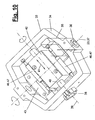
- This will be in FIG. 10 more clearly illustrated and consists of a housing (34), which may have, for example, a closed ring or frame shape and the bearing points (36,38) for the right angles intersecting rotary bearing axes (37,39).
- the housing (34) may further comprise an upstanding bracket (35), which in FIG. 8 is recognizable and that for the connection of one or more return elements (44) can serve.
- a bearing block (42) In the housing interior, a bearing block (42) is arranged, which by means of a sliding bearing (40) on the bearing shaft of the pivot bearing (38) along and in the direction (41) is displaceable. On both sides of the bearing block (42) can be arranged oppositely directed restoring elements (46) which have resilient properties and, for. are formed as gas springs (47). They center the bearing block (42) on the axis (39,41) with unloaded gripper (14).
- a connecting flange (43) is arranged, on which a gripping element (31) is located.
- the bearings (36,38,40) of the connecting flange (43) and the gripping member (31) are multi-axially movable and in particular gimbal and slidably mounted relative to the adjacent frame members (15,16,17).
- FIGS. 3 to 5 schematically show an arrangement of the return elements (44,45,46), all, for example, as springs, in particular as gas springs (47) are formed.
- the return elements (44) engage in this case on the gripper (14), in particular on the hinge unit (33), for example on the housing (34) or on the bracket (35) on both sides and are connected to the respectively adjacent frame member (15,16, 17).
- a symmetrical arrangement and design may be present, which acts on the rotation of the gripper (14) about the aligned pivot axes (23,37) and according to FIGS. 6 and 7 the gripper (14) in each case centrally relative to the adjacent frame members (15,16,17) and their side parts (19) aligns.
- the normal on the preferably flat gripping surface of the gripper (14) and the gripping element (31) extends on the bisector between the side parts (19). By this arrangement extend at an arcuate curved frame (13), the gripper (14) also along the curved envelope.
- the gripping elements (31) grasp one or more workpieces (8) in a point or surface shape and can be designed in any suitable manner.
- elongated surface gripper which are equipped with a squeegee.
- the deformable squeegee may be pressure sensitive and build up a suction pressure locally only upon contact with a workpiece area and corresponding deformation of its foam pad.
- Such a suction or surface gripper can eg according to the DE 102 16 221 C1 be educated. It enables a selective or joint gripping of several possibly spaced apart workpieces (8).
- the gripping element (31) consist of one or more magnets.
- additional gripper may be present, which are designed as a pivotable hook and the held workpiece (8) engage under the end and possibly center.
- the gripping element (31) can consist of several segments. It can be controlled in total or in segments.
- FIGS. 11 to 15 show an application of the gripping tool (1) when handling bent or marantelter workpieces (8), for example, have the trough-shaped or concave uniform circular arc shape shown.
- FIG. 1 is the frame (13) first in Stretched position.
- a suitable entrained or external measuring device (48) the actually existing workpiece shape can be determined by, for example, centrally and at the ends of the frame (13) the local distance to the workpiece (8) is measured. From the distances from a reference position, the workpiece contour or arc shape can be determined. Subsequently, according to FIG.
- FIG. 12 by actuation of the adjusting devices (24) brought the frame (13) in a corresponding arc shape, wherein the grippers (14) are still distanced from the workpiece (8).
- the gripping tool (1) delivered to the workpiece (8) and takes this with the appropriately aligned grippers (14).
- the position precisely recorded workpiece (8) is released from the substrate.
- This can be, for example, a stack (9) of several workpieces (8).
- FIG. 14 clarifies this position.
- the workpiece (8) can then be transported to the desired depositing and discharged.
- FIG. 15 shows a variant in which the workpiece (8) from the originally curved shape, which is possibly caused by the stack (9) is brought into an extended position.
- the frame (13) is brought into an extended position by returning the adjusting devices (24). Due to the multi-axis mounting, the grippers (14) can follow this movement, wherein in particular a movement along the workpiece (8) through the sliding axis (41) is possible. During this stretching process, the grippers (14) remain connected to the workpiece (8).
- FIGS. 16 to 20 show another functional variant in which a flat workpiece (8) from the gripping tool (1) with the stretched frame (13) according to FIGS. 16 and 17 is seized.
- the substrate workpiece (8) In order to be able to loosen the possibly adhering to the substrate workpiece (8), it is from the substrate, such as a stack (9), peeled off.
- the frame (13) is raised at both ends and in an arc shape brought.
- the workpiece (8) dissolves the edge of the substrate and is deformed arcuately.
- FIGS. 18 and 19 can the recorded workpiece (8) then released from the ground and possibly according to FIG. 20 then be put back in stretched position.
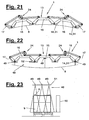
- FIG. 22 illustrates an exemplary embodiment of an entrained measuring device (48).
- one or more distance knives (49) are arranged on the frame (13), which may be located centrally on the central part (15) and on the end-side grippers (14) and the distance of the in a suitable position and alignment over the workpiece (8 ) held frame (13) relative to the workpiece (8) measure.
- one or more further measuring devices eg a moisture meter (52), can be arranged on the gripping tool (1).
- the distance and moisture meters (49,52) may be formed as a suitable non-contact sensors.
- further measuring elements for determining workpiece properties may be present.
- FIG. 23 shows a variant of a stationary measuring device (48), in which, for example, a plurality of distance blades (49) on a stationary frame (51) at a distance above a workpiece (8) are arranged, which is optionally on a stack (9).
- the distance measurer (49) measure here at several suitable locations the distance from a possibly non-linearly shaped workpiece (8).
- the reference numeral (50) indicates the measuring range of the measuring device (48), via which the height position of the uppermost workpiece (8) in the stack (9) can be determined.
- the measuring cones of the distance meter (49) may overlap each other if necessary.
- FIGS. 24 to 27 show variants of the frame training.
- the frame (13) has an even number of frame members (15, 16, 17), eg six.
- the crank arms (29,30) can cross each other in the middle.
- the end members (17) adjusting devices (24) may be mounted with possibly only one crank arm (29,30). Due to the larger frame length and the correspondingly increased number of grippers (14) larger workpieces (8) can be gripped. In addition, a stronger bend of the frame (13) is possible.
- FIG. 25 seven frame members (15,16,17) with four adjusting devices (24) are present, wherein the central member (15) two crank arms (29,30) attack on both sides.
- This variant corresponds in the kinematics of the embodiment described above of FIGS. 1 to 22 and is extended by additional intermediate links (16) and adjusting devices (24).
- FIG. 26 shows a further enlargement of the frame (13) of FIG. 24 by additional installation of two further pontics (16).
- FIG. 27 goes to the embodiment of FIG. 25 back, which is also extended by two additional intermediate links (16).
- the outer adjusting devices (24) are in this case formed with two arms.
- FIG. 1 shows in conjunction with FIG. 28 and 29 the use of a handling device (2) as a stacking device.
- the manipulator (3,4,5) is multi-axially formed in this embodiment and formed, for example, as a six-axis articulated arm robot. This has three rotary arm axes and a robot hand (6), which also has three rotational orthogonal hand axes.
- workpieces (8) are gripped by a stack (9).
- the stack (9) can include various elements and be a so-called mixed stack (57). In the exemplary embodiment shown, it consists of the workpieces (8) and in each case intermediate inserts (10). Both (8,10) can be gripped and handled with the same gripping tool (1).
- the handling station (7) of FIG. 28 and 29 is designed as a repacking station and has three handling devices (2) with manipulators (3,4,5) and gripping tools (1).
- the workpieces (8) are formed here substantially plate-shaped and consist of boards or panels made of wood.
- the handling station (7) also has a conveyor (53), here four parallel conveyor tracks (54) for different stacks (9,56,57,58) and also a running at the web end cross conveyor (55), for example a sliding carriage can.
- the stacks (9, 56, 57, 58) are movable with suitable carriers, for example pallets, on the conveyor tracks (54) formed, for example, as roller conveyors. In the illustrated embodiment, it is about the drying of wet wood parts.
- inserts (10) in the form of drying sheets are introduced between the wooden parts of the workpieces (8), which allow the dry air to flow through.
- the wooden parts (8) supplied on a feed stack (56) are received at the tail by the manipulator (3) with its gripping tool (1), wherein over the flexibility of the gripping tool (1) a delay or a misalignment of the wood parts in the feed stack (56 ) can be taken into account and compensated.
- the wooden parts (8) are then piled up on a mixing stack (57) with the interposition of drying sheets (10).
- the drying plates (10) are supplied by the manipulator (5).
- the mixing stack (57) can then be fed via the conveyor (53) of the drying plant.
- the mixing stack (57) is again the handling station (7) on the other conveyor track (54) supplied and unstacked by the manipulators (4,5).
- the dried wood parts (8) are piled up to a filing stack (58).
- the liberated drying sheets (10) can be fed directly to the new mixing stack (57) or optionally buffered to one or more shelves (11).
- the gripping tool (1) With the gripping tool (1) from the stack (9) several wood parts (8) can be grasped simultaneously. In particular, an entire wooden layer can be grasped and handled.
- the measuring device (48) here e.g. is arranged on a bridge-like stationary frame (51), allows a position and shape detection of the wooden parts (8).
- the gripping tool (1) extends beyond the stack limits and allows a secure detection of the wood parts, even with skewing or other pile deformations.
- the misplacements occurring in this case can be detected by the measuring device (48) and taken into account in the supply of the recorded wood parts (8) to the intermediate stack (57) and compensated by a correspondingly changed guide movement of the manipulator (3) for a correct position delivery.
- the drying plates (10) may also have deformations which manifest themselves in the stacked form of the mixing stacks (57). Such errors can also be detected by the measuring device (48) and taken into account and compensated for when stacking with the manipulator (4) to form an exact storage stack (58).
- the gripping tool (1) can change the picking and depositing order of the workpieces (8) as desired. For example, it can remove two or more layers of workpieces (8) one above the other, eg with the right, middle and left sides of the gripper (14). It can then put the workpieces (8) individually or together. When stacking, narrow stacks can be used on wide Stacks are rearranged and vice versa.
- This relates to the structural design of the gripping tool (1), the handling device (2) and the handling station (7) and the function and kinematics of the gripping tool (1).
- the gripper (14) can have one or more rotational axes and at least one translational axis.
- the gripper (14) can be pivotally mounted (36) on at least one frame member (15,16,17), wherein the bearing axes (23,37) of the pivot bearing (22,36) of the frame members (15,16,17) and the Gripper (14) are not aligned.
- the gripping element (31) of the gripper (14) need not be controllable.
- the gripper (14) has a hinge unit (33) which has two pivot bearings (36, 38) with intersecting bearing axes (37, 39) and a sliding bearing (40).
- the hinge unit (33) has a frame-like housing (34) with the pivot bearings (36,38) and a connecting flange (43) for the gripping element (31) which is displaceably guided on the one bearing axis (39).
- the return element (44,45,46) of the gripper (14) is in any way elastic and e.g. formed as a gas spring (47).
- the gripper (14) is connected by return elements (44) with the adjacent frame members (15,16,17).
- the return elements (44) align the gripper (14) on the bisecting line between the adjacent frame members (15,16,17).
- the gripping element (31) is connected to the housing (34) of the joint unit (33) by return elements (45).
- the connecting flange (43) is connected to the housing (34) of the joint unit (33) by return elements (46).
- crank mechanism (27) of the adjusting device (24) has a centrally mounted crank pulley (28) and crank arms (29, 30) connected diametrically opposite thereto.
Abstract
Description
Die Erfindung betrifft ein Greifwerkzeug für ein oder mehrere Werkstücke.The invention relates to a gripping tool for one or more workpieces.
Aus der Praxis sind robotergeführte Greifwerkzeuge in verschiedenen Ausführungsformen bekannt. Sie besitzen ein starres Gestell, welches über einen Anschluss mit der Hand eines Roboters oder anderen Manipulators verbunden werden kann. Am Gestell sind mehrere Greifer befestigt. Die vorbekannten Greifwerkzeuge sind durch ihre starre Gestaltung auf bestimmte Werkstücke adaptiert.From practice robotic gripping tools are known in various embodiments. They have a rigid frame, which can be connected via a port with the hand of a robot or other manipulator. On the frame several grippers are attached. The previously known gripping tools are adapted by their rigid design to certain workpieces.
Aus der
Die
Die
Aus der
Es ist Aufgabe der vorliegenden Erfindung, ein besseres Greifwerkzeug mit erweitertem Einsatzbereich und Zusatzfunktionen aufzuzeigen.It is an object of the present invention to provide a better gripping tool with a wider range of applications and additional functions.
Die Erfindung löst diese Aufgabe mit einem Greifwerkzeug gemäß Anspruch 1 und einem Verfahren gemäß Anspruch 15.The invention solves this problem with a gripping tool according to
Das mehrgliedrige Gestell hat den Vorteil, dass es sich an unterschiedliche Werkstückgeometrien anpassen kann. Dies ist insbesondere günstig, wenn die Werkstücke zu Formänderungen neigen oder in Stapelform vorliegen. Innerhalb eines Stapels können Werkstücke durch gegenseitiges Verschieben, eine schräge oder windschiefe Stapelform oder dergl. sich durch äußere Einflüsse verformen. Außerdem ist das beanspruchte Greifwerkzeug auch für die Handhabung unterschiedlicher Werkstücke geeignet. Durch die bevorzugt steuerbare Stelleinrichtung kann das mehrgliedrige Gestell in die jeweils gewünschte oder benötigte Form gebracht werden.The multi-unit frame has the advantage that it can adapt to different workpiece geometries. This is particularly favorable if the workpieces tend to change shape or in stack form. Within a stack, workpieces can be deformed by external displacement, a skewed or skewed stack shape or the like. In addition, the claimed gripping tool is also suitable for handling different workpieces. Due to the preferably controllable adjusting device, the multi-unit frame in the respectively desired or required shape.
Das verstellbare Greifwerkzeug kann außerdem Zusatzfunktionen bei der Handhabung der Werkstücke erfüllen. Einerseits kann die Formgebung des Werkstücks durch eine Verstellung des Gestells geändert werden, wobei ein anfangs gewölbtes Werkstück z.B. gestreckt werden kann. Auch eine umgekehrte Verformung ist möglich. Ferner kann durch eine Veränderung der Gestellgeometrie unter Mitnahme des gegriffenen Werkstücks eine Vereinzelung oder ein Abschäleffekt stattfinden. Dies erleichtert das Greifen von Werkstücken aus einem Stapel.The adjustable gripping tool can also fulfill additional functions in the handling of the workpieces. On the one hand, the shaping of the workpiece can be changed by an adjustment of the frame, wherein an initially curved workpiece, e.g. can be stretched. A reverse deformation is possible. Furthermore, a separation or a peeling effect can take place by changing the frame geometry, taking along the gripped workpiece. This facilitates the gripping of workpieces from a stack.
Die mit den beweglichen Gestellgliedern verbundenen Greifer können den Formänderungen des mehrgliedrigen Gestells folgen und sich ebenfalls an die geänderte Geometrie anpassen. Hierfür können insbesondere die Greifer ein oder mehrere Bewegungsachsen aufweisen. Dies bietet eine zusätzliche Anpassungsmöglichkeit des Greifwerkzeugs an die Werkstück- oder Stapelgeometrie.The grippers connected to the movable frame members can follow the changes in shape of the multi-unit frame and also adapt to the changed geometry. For this purpose, in particular the grippers may have one or more axes of movement. This offers an additional possibility of adaptation of the gripping tool to the workpiece or stack geometry.
Das beanspruchte Greifwerkzeug kann für unterschiedlichste Zwecke und Werkstücke eingesetzt werden. Durch seine Flexibilität bietet es eine hohe Betriebs- und Funktionssicherheit. Außerdem lassen sich die Anpassungen sehr schnell durchführen, was der Taktzeit und der Wirtschaftlichkeit des flexiblen Greifwerkzeugs im industriellen Einsatz zugute kommt.The claimed gripping tool can be used for a wide variety of purposes and workpieces. Its flexibility offers high operational and functional safety. In addition, the adjustments can be carried out very quickly, which benefits the cycle time and cost-effectiveness of the flexible gripping tool in industrial use.
Die Greifer können in beliebig geeigneter Weise ausgebildet und angeordnet sein. Besonders günstig ist eine Anordnung an den Verbindungsstellen der Gestellglieder. Hierdurch können die Greifer den Geometrieänderungen des Gestells und insbesondere einer hierdurch gebildeten Rundung folgen. Rückstellelemente halten hierbei die Greifer in einer Mittellage bzw. auf einer Winkelhalbierenden gegenüber den benachbarten Gestellgliedern und sorgen im Entlastungsfall für die Rückstellung in eine Ausgangsposition. Hierbei ist es günstig, wenn die Greifer gleichachsig mit den benachbarten Gestellgliedern schwenkbar gelagert sind. Über ein oder mehrere weitere rotatorische und/oder translatorische Achsen können Anpassungen der Greifer an die Werkstück- und Stapelgeometrie sicher gestellt werden. Weitere Rückstellelemente, die z.B. allesamt als Gasfedern ausgebildet sein können, sorgen für definierte Ausgangslagen in einer Ruhe- und Entlastungsstellung. Eine kardanische Lagerung der Greifer ist besonders günstig. Eine Schiebelagerung erlaubt ein Nachführen der Greifer bei Biegungen und Streckungen der Werkstücke und des mehrgliedrigen Gestells.The grippers can be designed and arranged in any suitable manner. Particularly favorable is an arrangement at the connection points of the frame members. As a result, the grippers can follow the changes in geometry of the frame and in particular a rounding formed thereby. Reset elements hold the grippers in a central position or on an angle bisecting the adjacent ones Frame members and provide in the case of relief for the provision in a starting position. It is advantageous if the grippers are mounted coaxially with the adjacent frame members pivotally. Adjustments of the grippers to the workpiece and stack geometry can be ensured via one or more further rotary and / or translatory axes. Other restoring elements, which may be formed as gas springs, for example, provide for defined starting positions in a rest and relief position. A gimbal bearing of the gripper is particularly favorable. A sliding bearing allows tracking of the gripper in bends and elongations of the workpieces and the multi-unit frame.
Die Stelleinrichtung kann in beliebig geeigneter Weise ausgebildet sein. Sie kann insbesondere z.B. einen fernsteuerbaren Stellantrieb mit ein oder mehreren Stellelementen aufweisen. Der beanspruchte Kurbeltrieb hat den Vorteil, dass mit einem Antrieb mehrere Gestellglieder betätigt werden können. Durch Wahl einer geeigneten Kurbelgeometrie können die gegenseitigen Verstellungen und Winkellagen der Gestellglieder in der gewünschten Weise beeinflusst und eingestellt werden. Insbesondere lassen sich durch einen symmetrischen Kurbeltrieb gleichmäßige Gliederbewegungen erreichen, wobei das Gestell mit den Greifern z.B. eine kreisrunde Kontur oder eine von der Kreisform in beliebiger weise abweichende gebogene Kontur einnehmen kann. Durch Variation der Zahl der Gestellglieder können kleinere oder größere Greifwerkzeuge mit entsprechend veränderlichen Verstellmöglichkeiten geschaffen werden.The adjusting device can be designed in any suitable manner. In particular, it may be e.g. have a remotely controllable actuator with one or more actuators. The claimed crank mechanism has the advantage that several frame members can be actuated with one drive. By choosing a suitable crank geometry, the mutual adjustments and angular positions of the frame members can be influenced and adjusted in the desired manner. In particular, uniform symmetry movements can be achieved by means of a symmetrical crank drive, the frame being provided with the grippers, e.g. a circular contour or one of the circular shape in any way different curved contour can take. By varying the number of frame members smaller or larger gripping tools can be created with correspondingly variable adjustment.
Das flexible Greifwerkzeug kann zusammen mit einem Manipulator eine Handhabungseinrichtung bilden, die für beliebige Zwecke und in beliebigen Branchen eingesetzt werden kann. Ein vorteilhafter Anwendungsbereich liegt bei Stapeleinrichtungen, mit denen Werkstückstapel auf- und abgebaut werden können, wobei auf die je nach Stapelhöhe, Werkstückgeometrie oder aus anderen Gründen veränderliche Stapelform Rücksicht genommen werden kann. Auch eventuelle Formänderungen durch Zwischenlagen, Werkstückverzüge oder aus anderen Gründen können ohne Beeinträchtigung der Staplerfunktion kompensiert werden. Weitere Anwendungsbereiche liegen beim Handling geschüsselter oder anderer Werkstücke mit runden oder anderen Formgebungen. Im Fahrzeugbau liegt ebenfalls eine vorteilhafte Einsatzmöglichkeit, z.B. beim Zuführen und lagegenauen Anpressen von Karosserieteilen, z.B. Dachblechen, an andere gewölbte oder in sonstiger Weise linear oder nicht linear geformte andere Fahrzeugteile, z.B. Seitenwände. Das flexible Greifwerkzeug kann sich mit dem gehaltenen Karosseriebauteil an die ggf. toleranzbehaftete oder aus anderen Gründen veränderliche Form der anderen Fahrzeugteile anpassen und für eine gleichmäßige Anpressung und Anlage des mitgeführten Werkstücks sorgen.The flexible gripping tool can form together with a manipulator a handling device that can be used for any purpose and in any industry. An advantageous application is included Stacking devices with which workpiece stack can be assembled and disassembled, which can be taken into account depending on the stack height, workpiece geometry or other reasons variable stack shape. Also possible changes in shape due to intermediate layers, workpiece distortions or other reasons can be compensated without affecting the stacker function. Further areas of application are the handling of bowled or other workpieces with round or other shapes. In vehicle construction is also an advantageous use, for example, when feeding and accurate pressing of body parts, such as roof panels, other curved or otherwise linear or non-linearly shaped other vehicle parts, such as side walls. The flexible gripping tool can be adapted with the held body part to the possibly tolerant or otherwise changeable shape of the other vehicle parts and ensure uniform contact pressure and conditioning of the entrained workpiece.
Das flexible Greifwerkzeug kann mit ein oder mehreren mitgeführten oder externen Messeinrichtungen kombiniert werden, um Werkstückeigenschaften, z.B. die aktuelle Formgebung der Werkstücke, ihre Oberflächenbeschaffenheit, die Feuchtigkeit von Holzwerkstücken oder dergl. zu erfassen und für die Steuerung des Greifwerkzeugs und der Handhabungseinrichtung heranzuziehen. Hierbei können z.B. durch ein mit räumlichem Übermaß ausgebildetes Greifwerkzeug Werkstücke in Fehllagen gegriffen werden, wobei auch die Fehlposition nach ein oder mehreren Achsen erfasst wird. Bei der Abgabe des Werkstücks kann durch eine entsprechende Bewegungskorrektur des Manipulators die Fehllage wieder ausgeglichen und das Werkstück in der korrekten Soll-Lage abgegeben werden. Diese Lagekorrekturen können sehr schnell und während des Handlingbetriebs durchgeführt werden. Die Handhabungseinrichtung hat dadurch eine sehr hohe Greif- und Positionsgenauigkeit und eine große Handlingkapazität.The flexible gripping tool may be combined with one or more entrained or external measuring devices to detect and utilize workpiece properties, such as the actual shape of the workpieces, their surface finish, the moisture of wood workpieces or the like, for the control of the gripping tool and the handling device. In this case, for example, workpieces can be gripped in misplaced positions by means of a spatially oversized gripping tool, whereby the incorrect position is also detected by one or more axes. When dispensing the workpiece, the misalignment can be compensated again by a corresponding movement correction of the manipulator and the workpiece can be delivered in the correct desired position. These position corrections can be carried out very quickly and during the handling operation. The handling device thereby has a very high gripping and positional accuracy and a large handling capacity.
Ein oder mehrere Handhabungseinrichtungen können in einer Handhabungsstation angeordnet sein und in abgestimmter Weise zusammenwirken. Ein bevorzugter Einsatzbereich ist das Umstapeln von Werkstücken unter Bildung von Zwischenstapeln aus verschiedenen Werkstücken oder Werkstücken und Einlagen. Ein solcher Zwischenstapel kann umgekehrt wieder entstapelt und zurücksortiert werden, wobei ein sortenreiner Ablagestapel von Werkstücken gebildet werden kann.One or more handling devices may be located in a handling station and cooperate in a coordinated manner. A preferred area of use is the restacking of workpieces to form intermediate stacks of different workpieces or workpieces and inserts. Conversely, such an intermediate stack can be unstacked again and sorted back, whereby a sorted stack of workpieces can be formed.
Das Greifwerkzeug kann mehrere Werkstücke gleichzeitig oder nacheinander aufnehmen und wieder ablegen, wobei die Aufnahme- und Ablagereihenfolge beliebig geändert werden kann. Dies ermöglicht ein Sortieren von Werkstücken und erlaubt die Bildung und Änderung beliebiger Stapelformen. Werkstücke können auch ohne Stapel aufgenommen, transportiert, evtl. in ihrer Lage und Ausrichtung geändert und gleich wieder abgelegt werden. Die Handhabungsprozesse sind beliebig wählbar.The gripping tool can record several workpieces at the same time or one after another and put them down again, whereby the picking and storage order can be changed as desired. This allows sorting of workpieces and allows the formation and modification of any stack shapes. Workpieces can also be picked up without a stack, transported, possibly changed in their position and orientation and immediately stored again. The handling processes are arbitrary.
Ein besonders geeigneter Einsatzzweck liegt beim Handling von Holzteilen, z.B. Brettern oder Paneelen, die in feuchtem Zustand auf einem Vorlagestapel zugeführt und für eine anschließende Trocknung in einen Mischstapel unter Einlage von Trockenblechen umgestapelt werden sollen. Nach der Trocknung kann der Mischstapel wieder umsortiert werden, wobei die getrockneten Holzteile zu einem Ablagestapel aufgeschichtet werden und die Trockenbleche zwischengepuffert oder direkt zur Bildung eines neuen Zwischenstapels mit feuchten Holzteilen wiederverwendet werden.A particularly suitable use is in the handling of wood parts, e.g. Boards or panels, which are to be supplied in a wet state on a feed stack and to be stacked for subsequent drying in a mixing stack with the insertion of dry metal sheets. After drying, the mixed stack can be rearranged again, the dried wood parts are stacked into a discard pile and the dryers are buffered or reused directly to form a new intermediate stack with wet wood parts.
In den Unteransprüchen sind weitere vorteilhafte Ausgestaltungen der Erfindung angegeben.In the subclaims further advantageous embodiments of the invention are given.
Die Erfindung ist in den Zeichnungen beispielsweise und schematisch dargestellt. Im Einzelnen zeigen:
- Figur 1:
- eine Handlingeinrichtung mit einem flexiblen Greifwerkzeug und einem Werkstückstapel in Seitenansicht,
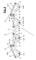
- Figur 2:
- das
Greifwerkzeug von Figur 1 in einer vergrößerten und schematisierten Ansicht, Figur 3 bis 7:- ein Greifwerkzeug und dessen Teile mit mehreren Bewegungsachsen in verschiedenen geklappten Ansichten und Winkelstellungen,
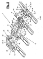
Figur 8 und 9:- ein flexibles Greifwerkzeug in stärkerer Detailierung und in verschiedenen perspektivischen Ansichten,
- Figur 10:
- eine perspektivische Ansicht einer Gelenkeinheit des Greifwerkzeugs,
Figur 11 bis 15:- ein Greifwerkzeug beim Handling geschüsselter Werkstücke in verschiedenen Funktions- und Bewegungsabschnitten,
Figur 16 bis 20:- ein Greifwerkzeug beim Greifen und Abschälen von Werkstücken in verschiedenen Funktions- und Bewegungsschritten,
- Figur 21:
- ein Greifwerkzeug in anderer Ausrichtung,
- Figur 22:
- ein Greifwerkzeug mit einer Messeinrichtung,
- Figur 23:
- eine Variante einer stationären Messeinrichtung,
Figur 24 bis 27:- verschiedene Varianten in Aufbau und Kinematik des Greifwerkzeugs und
Figur 28 und 29:- eine Handlingstation mit mehreren Handlingeinrichtungen und Greifwerkzeugen in Draufsicht und perspektivischer Ansicht.
- FIG. 1:
- a handling device with a flexible gripping tool and a workpiece stack in side view,
- FIG. 2:
- the gripping tool of
FIG. 1 in an enlarged and schematized view, - FIGS. 3 to 7:
- a gripping tool and its parts with several axes of movement in different folded views and angular positions,
- FIGS. 8 and 9:
- a flexible gripping tool in more detail and in different perspective views,
- FIG. 10:
- a perspective view of a hinge unit of the gripping tool,
- FIGS. 11 to 15:
- a gripping tool when handling sliced workpieces in various functional and movement sections,
- FIGS. 16 to 20:
- a gripping tool when gripping and peeling off workpieces in various functional and moving steps,
- FIG. 21:
- a gripping tool in a different orientation,
- FIG. 22:
- a gripping tool with a measuring device,
- FIG. 23:
- a variant of a stationary measuring device,
- FIGS. 24 to 27:
- different variants in construction and kinematics of the gripping tool and
- FIGS. 28 and 29:
- a handling station with several handling devices and gripping tools in plan view and perspective view.
Die Erfindung betrifft eine Greifeinrichtung (1), die zur werkzeugartigen Handhabung mittels einer Handhabungseinrichtung (2) geeignet und vorgesehen ist und die nachfolgend als Greifwerkzeug bezeichnet wird. Die Erfindung betrifft ferner eine mit dem Greifwerkzeug (1) ausgerüstete Handhabungseinrichtung (2) und auch eine mit ein oder mehreren Handhabungseinrichtungen (2) ausgestattete Handhabungsstation (7). Die Erfindung befasst sich außerdem mit einem Verfahren zum Handhaben von Werkstücken (8).The invention relates to a gripping device (1) which is suitable and intended for tool-like handling by means of a handling device (2) and which is referred to below as gripping tool. The invention further relates to a handling device (2) equipped with the gripping tool (1) and also to a handling station (7) equipped with one or more handling devices (2). The invention is also concerned with a method of handling workpieces (8).
Das Greifwerkzeug (1) dient zum Greifen und Handhaben von ein oder mehreren Werkstücken (8), die beliebig ausgebildet sein können. In den gezeigten Ausführungsformen sind im wesentlichen ebene und relativ dünne Werkstücke in Plattenform dargestellt. Dies können z.B. Bretter, Paneele, Platten oder dergl. aus Holz, Metall, Kunststoff oder sonstigen Materialien sein. Abweichend von den gezeigten Ausführungsbeispielen können die Werkstücke (8) auch eine andere Formgebung haben und z.B. als ein- oder mehrfach gewölbte Teile, z.B. Rohre, Wannen oder dergl. ausgebildet sein. Ferner können die Werkstücke (8) beliebige andere Formen, z.B. abgestufte oder zerklüftete Formen oder dergl. haben.The gripping tool (1) is used for gripping and handling of one or more workpieces (8), which may be of any desired design. In the embodiments shown, substantially planar and relatively thin workpieces are shown in sheet form. This can e.g. Planks, panels, plates or the like of wood, metal, plastic or other materials. Notwithstanding the embodiments shown, the workpieces (8) may also have a different shape and e.g. as singly or multiply curved parts, e.g. Tubes, tubs or the like. Be formed. Further, the workpieces (8) may be any other shapes, e.g. have stepped or rugged shapes or the like.
Das Greifwerkzeug (1) ist flexibel und verstellbar und kann seine Geometrie steuerbar ändern. Es besteht in den verschiedenen Ausführungsformen jeweils aus einem mehrgliedrigen Gestell (13), dessen Gestellglieder (15,16,17) gelenkig miteinander verbunden sind. Das Greifwerkzeug (1) weist ferner mindestens eine steuerbare Stelleinrichtung (24) für die gegenseitige Verstellung von mehr als zwei Gestellgliedern (15,16,17) auf.The gripper tool (1) is flexible and adjustable and can change its geometry controllable. It consists in the various embodiments of each one multi-membered frame (13) whose frame members (15,16,17) are hinged together. The gripping tool (1) also has at least one controllable adjusting device (24) for the mutual adjustment of more than two frame members (15, 16, 17).
In den gezeigten Ausführungsformen sind die Gestellglieder (15,16,17) in einer Reihe hintereinander angeordnet und an den Verbindungsstellen (21) durch Lager (22), vorzugsweise Schwenklager, miteinander verbunden. Unter Einfluss der Stelleinrichtung (24) können sich die Gestellglieder (15,16,17) gegeneinander verdrehen und im Verlauf der Gliederkette eine beliebige Form annehmen. Dies kann z.B. die in
In Abwandlung der gezeigten Ausführungsform kann das Gestell (13) auch mehrere Reihen von Gestellgliedern (15,16,17) nebeneinander aufweisen. Die Gestellglieder (15,16,17) können hierbei auch quer miteinander verbunden sein und rasterförmig angeordnet sein.In a modification of the embodiment shown, the frame (13) may also have a plurality of rows of frame members (15, 16, 17) next to one another. The frame members (15, 16, 17) can in this case also be connected to one another transversely and arranged in a grid pattern.
Die Zahl der Gestellglieder (15,16,17) kann beliebig groß sein und beträgt mindestens zwei. Die Gliederzahl kann gerade oder ungerade sein. Im Ausführungsbeispiel von
Die Gestellglieder (15,16,17) können beispielsweise brückenartig oder bügelförmig ausgebildet sein.
Die Endglieder (17) können jeweils ein Seitenteil (19) aufweisen, welches zwei oder mehr Lagerarme besitzen kann, die durch ein Stegteil (20) zu einer Bügelform miteinander verbunden sind. Das Stegteil (20) kann außerdem einen längsgerichteten Fortsatz aufweisen, der ähnlich wie die Mittelteile (18) der anderen Gestellglieder (15,16) ausgebildet sein kann. Abweichend von den gezeigten Ausführungsbeispielen können die Gestellglieder (15,16,17) eine beliebige andere geeignete Formgebung haben.The end members (17) may each have a side part (19), which may have two or more bearing arms, which are connected by a web portion (20) to form a bow. The web part (20) may also have a longitudinal extension which may be similar to the middle parts (18) of the other frame members (15, 16). Notwithstanding the embodiments shown, the frame members (15,16,17) may have any other suitable shape.
Das Gestell (13) weist an geeigneter Stelle mindestens einen Anschluss (12) zur Verbindung mit einem Manipulator (3,4,5) auf. Der Anschluss (12) kann z.B. eine Flanschplatte zur festen oder lösbaren Verbindung mit dem Abtriebsflansch einer Manipulatorhand (6) sein. Der Anschluss (12) kann außerdem als Bestandteil einer Wechselkupplung ausgebildet sein. Der Anschluss (12) ist in den gezeigten Ausführungsbeispielen bevorzugt mittig am Gestell (13) und insbesondere am Mittelteil (18) von dessen Zentralglied (15) angeordnet. Durch die Stelleinrichtung (24) kann das mehrgliedrige Gestell (13) in der gewünschten Formgebung fixiert werden, wodurch es eine starre Einheit bildet. Der Anschluss (12) kann alternativ außermittig und z.B. an einem Zwischenglied (16) angeordnet sein. Es ist auch eine Mehrfachanordnung von Anschlüssen (12) möglich.The frame (13) has at a suitable point at least one connection (12) for connection to a manipulator (3,4,5). The terminal (12) may be e.g. a flange plate for fixed or detachable connection with the output flange of a manipulator hand (6). The connection (12) can also be designed as part of an exchangeable coupling. The connection (12) is preferably arranged centrally on the frame (13) and in particular on the middle part (18) of its central member (15) in the embodiments shown. By adjusting device (24), the multi-unit frame (13) can be fixed in the desired shape, whereby it forms a rigid unit. The port (12) may alternatively be off-center and e.g. be arranged on an intermediate member (16). It is also a multiple arrangement of terminals (12) possible.
Die Stelleinrichtung (24) kann einfach oder mehrfach vorhanden sein. Sie kann konstruktiv in beliebig geeigneter Weise ausgebildet sein und ist bevorzugt steuerbar. Sie besteht jeweils aus einem Stellantrieb (25) mit ein oder mehreren Stellelementen (26). Die ein oder mehreren Stelleinrichtungen (24) sind bevorzugt an einem Gestellglied (15,16,17) und insbesondere an dessen Mittelteil (18) außenseitig angeordnet. Über die besagten Stellelemente (26) wird eine Verbindung mit ein oder mehreren benachbarten Gestellgliedern (15,16,17) hergestellt. Durch Betätigung der Stellelemente (26) wird das jeweils benachbarte Gestellglied (15,16,17) um das Lager (22) an der Verbindungsstelle (21) bewegt, vorzugsweise geschwenkt. In Abweichung der gezeigten und beschriebenen Ausführungsformen kann alternativ oder zusätzlich eine translatorische Bewegung stattfinden. Ferner ist eine mehrachsige Bewegung mittels Kurvenbahnen oder dergl. möglich.The adjusting device (24) can be present once or several times. It may be designed constructively in any suitable manner and is preferably controllable. It consists of an actuator (25) with one or more actuators (26). The one or more adjusting devices (24) are preferably arranged on a frame member (15,16,17) and in particular on its central part (18) on the outside. About the said adjusting elements (26) is a connection with one or more adjacent frame members (15,16,17) produced. By actuating the adjusting elements (26), the respectively adjacent frame member (15, 16, 17) is moved around the bearing (22) at the connection point (21), preferably pivoted. In a departure from the embodiments shown and described, alternatively or additionally, a translatory movement may take place. Furthermore, a multi-axis movement by means of curved paths or the like. Possible.
In der gezeigten Ausführungsform weist die Stelleinrichtung (24) einen Kurbeltrieb (27) auf. Der Kurbeltrieb (27) besitzt eine um eine Zentralachse drehbar gelagerte und mit dem Stellantrieb (25) verbundene Kurbelscheibe (28), an der an geeigneter Stelle ein oder mehrere Kurbelarme (29,30) angeschlossen sind. In der Ausführungsform von
Der Stellantrieb (25) kann in beliebig geeigneter Weise ausgebildet sein, z.B. als Elektromotor mit einem Untersetzungsgetriebe. Der Stellantrieb (25) ist steuerbar und kann eine Positionssteuerung aufweisen, mittels der die Kurbelscheibe (28) in die gewünschte Drehstellung gebracht wird. Durch die symmetrische Kurbelscheibenausbildung werden die angeschlossenen Kurbelarme (29,30) in entgegengesetzten Richtungen und um gleiche Drehwinkel bewegt. Wenn auch die Kurbelarme (29,30) gleiche Längen haben, werden sie durch die Symmetrieanordnung um gleiche Wege bewegt. Bei symmetrischer Anordnung schwenken die benachbarten Gestellglieder (15,16,17) ebenfalls um gleiche Winkel. Hierdurch kann eine gleichmäßige runde und z.B. kreisbogenförmige Gestellform erreicht werden. Bei der Ausführungsform von
In der gezeigten Ausführungsform des Kurbeltriebs (27) bilden die Kurbelarme (29,30) die Stellelemente (26). In Abwandlung hierzu kann die Stelleinrichtung (24) von pneumatischen oder hydraulischen Zylindern, von motorisch angetriebenen Spindeln oder dergl. in Verbindung mit geeigneten gelenkigen Lagerungen gebildet werden.In the illustrated embodiment of the crank drive (27), the crank arms (29, 30) form the adjusting elements (26). In a modification to this, the adjusting device (24) of pneumatic or hydraulic cylinders, motor-driven spindles or the like. Can be formed in conjunction with suitable articulated bearings.
Ferner ist es möglich, dass die Stelleinrichtung(en) (24) Fixiermittel für ein oder mehrere vorgegebene oder frei bestimmbare Positionen aufweist. Dies können beispielsweise Anschläge für Endstellungen, Rasten für Zwischenstellungen oder dergl. sein. Ferner können Klemmeinrichtungen, z.B. Bremsen oder dergl. zur Fixierung der eingenommenen Bewegungsposition vorhanden sein. Für eine geeignete Positionssteuerung sind außerdem Wege- oder Winkelmesssysteme oder andere geeignete Messeinrichtungen vorhanden.Furthermore, it is possible that the adjusting device (s) (24) has fixing means for one or more predetermined or freely determinable positions. These may be, for example, stops for end positions, stops for intermediate positions or the like. Furthermore, clamping means, e.g. Brakes or the like. To fix the occupied movement position be present. For a suitable position control also way or angle measuring systems or other suitable measuring devices are available.
An den Gestellgliedern (15,16,17) sind ein oder mehrere Greifer (14) angeordnet, die zur lösbaren Aufnahme von ein oder mehreren Werkstücken (8) ausgebildet und angeordnet sind. Die Greifer (14) befinden sich in den gezeigten Ausführungsformen im Bereich der Verbindungsstellen (21) zwischen den Gestellgliedern (15,16,17). Sie können zusätzlich oder alternativ an anderen Stellen und in anderer Zahl an den Gestellgliedern (15,16,17) angeordnet sein.On the frame members (15,16,17) one or more grippers (14) are arranged, which are designed and arranged for releasably receiving one or more workpieces (8). The grippers (14) are located in the embodiments shown in the region of the connection points (21) between the frame members (15,16,17). They may additionally or alternatively be arranged at other locations and in a different number on the frame members (15, 16, 17).
Der einzelne Greifer hat bevorzugt ein oder mehrere Bewegungsachsen und kann seine Lage gegenüber den ein oder mehreren benachbarten Gestellgliedern (15,16,17) ändern. Der Greifer (14) hat hier z.B. eine rotatorische Bewegungsachse oder Lagerachse (37). Er kann zusätzlich oder alternativ eine translatorische Bewegungsachse (41) aufweisen. Er kann ferner ein oder mehrere zusätzliche rotatorische und/oder translatorische Bewegungsachsen (39) besitzen. Durch die mehrachsige Lagerung kann der Greifer (14) sich nach dem oder den Werkstück(en) (8) ausrichten, wobei ein oder mehrere Rückstellelemente (44,45,46) im Achsenbereich wirksam sind und für eine Lagestabilisierung, insbesondere für eine Rückführung in eine vorgegebene Ausgangsstellung in Entlastungs- oder Ruheposition des Greifers (14) sorgen können.The single gripper preferably has one or more axes of motion and may change position relative to the one or more adjacent frame members (15, 16, 17). The gripper (14) has here, for example, a rotary movement axis or bearing axis (37). He may additionally or alternatively have a translational movement axis (41). He may also have one or more additional ones have rotational and / or translational movement axes (39). Due to the multi-axial bearing, the gripper (14) can be aligned with the workpiece (s) (8), wherein one or more restoring elements (44, 45, 46) are effective in the axis region and for a position stabilization, in particular for a return in a predetermined starting position in relief or rest position of the gripper (14) can provide.
Der Greifer (14) ist bevorzugt schwenkbar an zumindest einem Gestellglied (15,16,17) gelagert. Sein Schwenklager (36) und seine Lagerachse (37) fluchten mit dem Schwenklager (22) und der Lagerachse (36) der benachbarten Gestellglieder (15,16,17). Diese Lagerachsen (23,37) sind quer zur Längsrichtung des Gestells (13) ausgerichtet und erstrecken sich längs der bevorzugt länglich ausgebildeten Greifer (14).The gripper (14) is preferably pivotally mounted on at least one frame member (15,16,17). Its pivot bearing (36) and its bearing axis (37) are aligned with the pivot bearing (22) and the bearing axis (36) of the adjacent frame members (15,16,17). These bearing shafts (23, 37) are oriented transversely to the longitudinal direction of the frame (13) and extend along the preferably oblong grippers (14).
Wie
Im Gehäuseinnenraum ist ein Lagerblock (42) angeordnet, der mittels eines Schiebelagers (40) auf der Lagerwelle des Schwenklagers (38) längs und in Richtung (41) verschiebbar ist. Beidseits des Lagerblocks (42) können gegeneinander gerichtete Rückstellelemente (46) angeordnet sein, die federnde Eigenschaften haben und z.B. als Gasfedern (47) ausgebildet sind. Sie zentrieren den Lagerblock (42) auf der Achse (39,41) bei entlastetem Greifer (14).In the housing interior, a bearing block (42) is arranged, which by means of a sliding bearing (40) on the bearing shaft of the pivot bearing (38) along and in the direction (41) is displaceable. On both sides of the bearing block (42) can be arranged oppositely directed restoring elements (46) which have resilient properties and, for. are formed as gas springs (47). They center the bearing block (42) on the axis (39,41) with unloaded gripper (14).
An der Unterseite des Lagerblocks (42) ist ein Anschlussflansch (43) angeordnet, an dem sich ein Greifelement (31) befindet. Durch die Lager (36,38,40) sind der Anschlussflansch (43) und das Greifelement (31) mehrachsig beweglich und insbesondere kardanisch und verschiebbar gegenüber dem benachbarten Gestellgliedern (15,16,17) gelagert.On the underside of the bearing block (42), a connecting flange (43) is arranged, on which a gripping element (31) is located. By the bearings (36,38,40) of the connecting flange (43) and the gripping member (31) are multi-axially movable and in particular gimbal and slidably mounted relative to the adjacent frame members (15,16,17).
Am Greifelement (31) sind beidseits des querliegenden Schwenklagers (38) Rückstellelemente (45) angeschlossen und mit der Gelenkeinheit (33) gemäß
Die Greifelemente (31) fassen ein oder mehrere Werkstücke (8) punkt- oder flächenförmig und können in beliebig geeigneter Weise ausgebildet sein. Im gezeigten Ausführungsbeispiel handelt es sich um längliche Flächengreifer, die mit einer Saugleiste ausgestattet sind. Die deformierbare Saugleiste kann drucksensibel sein und nur bei Kontakt mit einem Werkstückbereich und einer entsprechenden Verformung ihres Schaumstoffkissens lokal einen Saugdruck aufbauen. Ein solcher Saug- oder Flächengreifer kann z.B. gemäß der
In der Variante von
Die Variante von
Die Variante von
Die Handhabungsstation (7) von
Mit dem Greifwerkzeug (1) können vom Stapel (9) mehrere Holzteile (8) gleichzeitig gegriffen werden. Insbesondere kann eine gesamte Holzlage gefasst und gehandhabt werden. Durch die Messeinrichtung (48), die hier z.B. an einem brückenartigen stationären Gestell (51) angeordnet ist, ermöglicht eine Lage- und Formerfassung der Holzteile (8). Das Greifwerkzeug (1) erstreckt sich über die Stapelgrenzen hinaus und ermöglicht eine sichere Erfassung der Holzteile auch bei Schiefstellungen oder anderen Stapelverformungen. Die hierbei auftretenden Fehllagen können über die Messeinrichtung (48) erkannt und bei der Zuführung der aufgenommenen Holzteile (8) zum Zwischenstapel (57) berücksichtigt sowie durch eine entsprechend geänderte Führungsbewegung des Manipulators (3) für eine lagerichtige Abgabe kompensiert werden.With the gripping tool (1) from the stack (9) several wood parts (8) can be grasped simultaneously. In particular, an entire wooden layer can be grasped and handled. By the measuring device (48), here e.g. is arranged on a bridge-like stationary frame (51), allows a position and shape detection of the wooden parts (8). The gripping tool (1) extends beyond the stack limits and allows a secure detection of the wood parts, even with skewing or other pile deformations. The misplacements occurring in this case can be detected by the measuring device (48) and taken into account in the supply of the recorded wood parts (8) to the intermediate stack (57) and compensated by a correspondingly changed guide movement of the manipulator (3) for a correct position delivery.
Auch die Trockenbleche (10) können Verformungen aufweisen, die sich in der Stapelform der Mischstapel (57) äußern. Derartige Fehler können ebenfalls durch die Messeinrichtung (48) erfasst und beim Umstapeln mit dem Manipulator (4) zur Bildung eines exakten Ablagestapels (58) berücksichtigt und kompensiert werden.The drying plates (10) may also have deformations which manifest themselves in the stacked form of the mixing stacks (57). Such errors can also be detected by the measuring device (48) and taken into account and compensated for when stacking with the manipulator (4) to form an exact storage stack (58).
Ferner kann das Greifwerkzeug (1) die Aufnahme- und Ablegereihenfolge der Werkstücke (8) beliebig ändern. So kann sie z.B. zwei oder mehr übereinander liegende Lagen von Werkstücken (8) nacheinander entnehmen, z.B. mit der rechten, mittleren und linken Seite des Greifers (14). Sie kann die Werkstücke (8) dann einzeln oder gemeinsam ablegen. Beim Umstapeln können schmale Stapel auf breite Stapel umgeschichtet werden und auch umgekehrt.Furthermore, the gripping tool (1) can change the picking and depositing order of the workpieces (8) as desired. For example, it can remove two or more layers of workpieces (8) one above the other, eg with the right, middle and left sides of the gripper (14). It can then put the workpieces (8) individually or together. When stacking, narrow stacks can be used on wide Stacks are rearranged and vice versa.
Abwandlungen der gezeigten und beschriebenen Ausführungsformen sind in verschiedener Weise möglich. Dies betrifft die konstruktive Ausbildung des Greifwerkzeugs (1), der Handhabungseinrichtung (2) und der Handhabungsstation (7) sowie die Funktion und Kinematik des Greifwerkzeugs (1).Variations of the embodiments shown and described are possible in various ways. This relates to the structural design of the gripping tool (1), the handling device (2) and the handling station (7) and the function and kinematics of the gripping tool (1).
Insbesondere können dessen Bestandteile konstruktiv anders ausgebildet und miteinander verbunden sein, wie nachstehend angegeben.In particular, its constituents may be structurally different and interconnected, as indicated below.
Der Greifer (14) kann eine oder mehrere rotatorische Achsen und mindestens eine translatorische Achse aufweisen.The gripper (14) can have one or more rotational axes and at least one translational axis.
Der Greifer (14) kann schwenkbar an zumindest einem Gestellglied (15,16,17) gelagert (36) sein, wobei die Lagerachsen (23,37) der Schwenklager (22,36) der Gestellglieder (15,16,17) und des Greifers (14) nicht miteinander fluchten.The gripper (14) can be pivotally mounted (36) on at least one frame member (15,16,17), wherein the bearing axes (23,37) of the pivot bearing (22,36) of the frame members (15,16,17) and the Gripper (14) are not aligned.
Das Greifelement (31) des Greifers (14) muss nicht steuerbar sein.The gripping element (31) of the gripper (14) need not be controllable.
Der Greifer (14) weist eine Gelenkeinheit (33) auf, die zwei Schwenklager (36,38) mit sich kreuzenden Lagerachsen (37,39) und ein Schiebelager (40) besitzt.The gripper (14) has a hinge unit (33) which has two pivot bearings (36, 38) with intersecting bearing axes (37, 39) and a sliding bearing (40).
Die Gelenkeinheit (33) weist ein rahmenartiges Gehäuse (34) mit den Schwenklagern (36,38) und einen Anschlussflansch (43) für das Greifelement (31) auf, welcher auf der einen Lagerachse (39) verschieblich geführt ist.The hinge unit (33) has a frame-like housing (34) with the pivot bearings (36,38) and a connecting flange (43) for the gripping element (31) which is displaceably guided on the one bearing axis (39).
Das Rückstellelement (44,45,46) des Greifers (14) ist in beliebiger Weise elastisch und z.B. als Gasfeder (47) ausgebildet.The return element (44,45,46) of the gripper (14) is in any way elastic and e.g. formed as a gas spring (47).
Der Greifer (14) ist durch Rückstellelemente (44) mit den benachbarten Gestellgliedern (15,16,17) verbunden.The gripper (14) is connected by return elements (44) with the adjacent frame members (15,16,17).
Die Rückstellelemente (44) richten den Greifer (14) auf die Winkelhalbierende zwischen den benachbarten Gestellgliedern (15,16,17) aus.The return elements (44) align the gripper (14) on the bisecting line between the adjacent frame members (15,16,17).
Das Greifelement (31) ist durch Rückstellelemente (45) mit dem Gehäuse (34) der Gelenkeinheit (33) verbunden.The gripping element (31) is connected to the housing (34) of the joint unit (33) by return elements (45).
Der Anschlussflansch (43) ist durch Rückstellelemente (46) mit dem Gehäuse (34) der Gelenkeinheit (33) verbunden.The connecting flange (43) is connected to the housing (34) of the joint unit (33) by return elements (46).
Der Kurbeltrieb (27) der Stelleinrichtung (24) weist eine zentral gelagerte Kurbelscheibe (28) und daran diametral gegenüberliegend angeschlossene Kurbelarme (29,30) auf.The crank mechanism (27) of the adjusting device (24) has a centrally mounted crank pulley (28) and crank arms (29, 30) connected diametrically opposite thereto.
- 11
- flexibles Greifwerkzeugflexible gripping tool
- 22
- Handhabungseinrichtunghandling device
- 33
- Manipulator, RoboterManipulator, robot
- 44
- Manipulator, RoboterManipulator, robot
- 55
- Manipulator, RoboterManipulator, robot
- 66
- Hand, RoboterhandHand, robot hand
- 77
- Handhabungsstationhandling station
- 88th
- Werkstück, BrettWorkpiece, board
- 99
- Stapelstack
- 1010
- Einlageinlay
- 1111
- Ablagefiling
- 1212
- Anschlussconnection
- 1313
- Gestell mehrgliedrigFrame multi-limbed
- 1414
- Greifergrab
- 1515
- Gestellglied, ZentralgliedFrame link, central link
- 1616
- Gestellglied, ZwischengliedFrame link, intermediate link
- 1717
- Gestellglied, EndgliedFrame link, end link
- 1818
- Mittelteilmidsection
- 1919
- Seitenteil, LagerarmSide part, bearing arm
- 2020
- Stegteilweb member
- 2121
- Verbindungsstellejunction
- 2222
- Lager, SchwenklagerBearing, swivel bearing
- 2323
- Lagerachsebearing axle
- 2424
- Stelleinrichtungsetting device
- 2525
- Stellantriebactuator
- 2626
- Stellelementactuator
- 2727
- Kurbeltriebcrankshaft
- 2828
- Kurbelscheibecrank
- 2929
- Kurbelarmcrank
- 3030
- Kurbelarmcrank
- 3131
- Greifelementgripping element
- 3232
- Flächengreifergrippers
- 3333
- Gelenkeinheitjoint unit
- 3434
- Gehäusecasing
- 3535
- Bügelhanger
- 3636
- Lager, SchwenklagerBearing, swivel bearing
- 3737
- Lagerachse längs, BewegungsachseBearing axis along, movement axis
- 3838
- Lager, SchwenklagerBearing, swivel bearing
- 3939
- Lagerachse quer, BewegungsachseBearing axis transverse, movement axis
- 4040
- Lager, SchiebelagerBearings, sliding bearings
- 4141
- Lagerachse, Schiebeachse, BewegungsachseBearing axis, sliding axis, movement axis
- 4242
- Lagerblockbearing block
- 4343
- Anschlussflanschflange
- 4444
- Rückstellelement für GreiferReset element for gripper
- 4545
- Rückstellelement für GreifelementReset element for gripping element
- 4646
- Rückstellelement für LagerblockReset element for storage block
- 4747
- Gasfedergas spring
- 4848
- Messeinrichtungmeasuring device
- 4949
- Abstandsmesser, SensorDistance meter, sensor
- 5050
- Messbereichmeasuring range
- 5151
- stationäres Gestellstationary rack
- 5252
- Feuchtemesser, SensorMoisture meter, sensor
- 5353
- FördereinrichtungConveyor
- 5454
- Förderbahnconveyor track
- 5555
- Querförderer, VerschiebewagenCross conveyor, transfer carriage
- 5656
- Vorlagestapelstack of documents
- 5757
- Mischstapelmixed batch
- 5858
- Ablagestapeldiscard pile
Claims (16)
- Gripping tool for one or more workpieces (8), having a frame (13), having a connection (12) for a manipulator (3, 4, 5) and having a plurality of grippers (14), wherein the frame (13) has more than two frame members (15, 16, 17) connected together in an articulated manner and at least one controllable actuating device (24) for the mutual adjustment thereof.
- Gripping tool according to Claim 1, characterized in that the frame members (15, 16, 17) are arranged in succession in at least one row and are connected at the connecting points (21) by bearings (22), in particular pivot bearings.
- Gripping tool according to Claim 1 or 2, characterized in that one or more grippers (14) are arranged on the frame members (15, 16, 17) in the region of the connecting points (21).
- Gripping tool according to Claim 1, 2 or 3, characterized in that the gripper (14) has one or more movement axes.
- Gripping tool according to one of the preceding claims, characterized in that the gripper (14) is mounted (36) pivotably on at least one frame member (15, 16, 17), wherein the bearing axes (23, 37) of the pivot bearings (22, 36) of the frame members (15, 16, 17) and of the gripper (14) are aligned.
- Gripping tool according to one of the preceding claims, characterized in that the gripper (14) has at least one controllable gripping element (31).
- Gripping tool according to one of the preceding claims, characterized in that the gripping element (31) is in the form of an area gripper (32).
- Gripping tool according to one of the preceding claims, characterized in that the gripping element (31) is mounted pivotably about a plurality of axes, in particular cardanically, and/or displaceably.
- Gripping tool according to one of the preceding claims, characterized in that the gripper (14) has at least one restoring element (44, 45, 46) in the region of at least one bearing axis (37, 39, 41).
- Gripping tool according to one of the preceding claims, characterized in that the actuating device (24) has an actuating drive (25) and one or more actuating elements (26).
- Gripping tool according to one of the preceding claims, characterized in that the actuating device (24) is arranged on a frame member (16) and is connected via the actuating elements (26) to the adjacent frame members (15, 16, 17).
- Gripping tool according to one of the preceding claims, characterized in that the actuating device (24) has a crank drive (27).
- Handling device for one or more workpieces (8), having a manipulator (3, 4, 5) which can be moved about one or more axes and having a gripping tool (1) which is arranged thereon and has a frame (13) and a plurality of grippers (14), characterized in that the gripping tool (1) is in the form according to one of Claims 1 to 12.
- Handling device according to Claim 13, characterized in that the handling device (2) is in the form of a stacking device.
- Method for handling one or more workpieces (8) with at least one handling device (2) having a manipulator (3, 4, 5) which can be moved about one or more axes and having a gripping tool (1) which is arranged thereon and has a frame (13) and a plurality of grippers (14), wherein the gripping tool (1) can be matched to a non-linear form of the workpiece (8) by changing the form of the frame (13), which has more than two frame members (15, 16, 17) connected together in an articulated manner and an actuating device (24) for the mutual adjustment thereof.
- Method according to Claim 15, characterized in that the shape of the gripped workpiece (8) can be changed and/or the gripped workpiece (8) can be separated or peeled off by changing the form of the frame (13).
Applications Claiming Priority (1)
| Application Number | Priority Date | Filing Date | Title |
|---|---|---|---|
| DE202007013673U DE202007013673U1 (en) | 2007-09-28 | 2007-09-28 | Flexible gripping device |
Publications (2)
| Publication Number | Publication Date |
|---|---|
| EP2042277A1 EP2042277A1 (en) | 2009-04-01 |
| EP2042277B1 true EP2042277B1 (en) | 2010-12-08 |
Family
ID=40220005
Family Applications (1)
| Application Number | Title | Priority Date | Filing Date |
|---|---|---|---|
| EP08016615A Not-in-force EP2042277B1 (en) | 2007-09-28 | 2008-09-22 | Flexible gripping tool |
Country Status (3)
| Country | Link |
|---|---|
| EP (1) | EP2042277B1 (en) |
| AT (1) | ATE490849T1 (en) |
| DE (2) | DE202007013673U1 (en) |
Families Citing this family (27)
| Publication number | Priority date | Publication date | Assignee | Title |
|---|---|---|---|---|
| IT1403858B1 (en) * | 2011-02-04 | 2013-11-08 | Gimatic Spa | EQUIPMENT FOR SIMULTANEOUS MANIPULATION OF MULTIPLE COMPONENTS |
| DE102011012082B4 (en) * | 2011-02-23 | 2014-11-06 | Audi Ag | Suction gripper for removing bulk material from a transport container |
| FR2991607B1 (en) * | 2012-06-07 | 2014-06-27 | Peugeot Citroen Automobiles Sa | BREAKING DETECTION ON BAKING PIECE WHEN HANDLING WITH A VENTOUS PREHENSER. |
| ITTO20130774A1 (en) * | 2013-09-26 | 2015-03-27 | O L C I Engineering S R L | LINE OF ASSEMBLY OF BODYWORK ELEMENTS OF MOTOR VEHICLES |
| EP2952302B1 (en) * | 2014-06-05 | 2019-03-20 | J. Schmalz GmbH | Gripping or holding device |
| EP2952303B1 (en) | 2014-06-05 | 2017-10-11 | J. Schmalz GmbH | Method for handling flexible mesh-like workpieces |
| JP6367158B2 (en) | 2015-07-13 | 2018-08-01 | 三菱重工業株式会社 | Adsorption device, gripping device, and conveying method |
| JP6382783B2 (en) | 2015-11-09 | 2018-08-29 | ファナック株式会社 | Suction type hand that picks up workpieces |
| DE102016125674A1 (en) * | 2016-12-23 | 2018-06-28 | Broetje-Automation Gmbh | end effector |
| JP6988541B2 (en) | 2018-02-15 | 2022-01-05 | トヨタ自動車株式会社 | Separator adsorption device |
| CN108381579B (en) * | 2018-04-26 | 2024-03-29 | 东莞市瑞立达玻璃盖板科技股份有限公司 | Positioning mechanism |
| DE102018116679B4 (en) * | 2018-07-10 | 2021-01-28 | Kallfass Gmbh Maschinen Plus Automation | System for magazining separating strips, system for binding board stacks and magazine |
| JP7161207B2 (en) | 2019-06-21 | 2022-10-26 | 株式会社イシダ | Goods discharge system |
| DE102019130375B4 (en) * | 2019-11-11 | 2023-02-16 | Fipa Holding Gmbh | SUCTION CUP ASSEMBLY FOR HANDLING OBJECTS |
| IT202000015316A1 (en) * | 2020-06-25 | 2021-12-25 | Euromatic Srl | ROBOT HEAD FOR PICKING GLASS CONTAINERS |
| DE102020216558A1 (en) | 2020-11-20 | 2022-05-25 | Christian Borger | System and method for handing over a large number of parcels to a number of recipients and/or for receiving a large number of parcels from a number of posters |
| DE102021200970A1 (en) | 2020-11-20 | 2022-05-25 | Christian Borger | System and method for handing over a large number of parcels to a number of recipients and/or for receiving a large number of parcels from a number of posters |
| DE102020215228B3 (en) | 2020-12-02 | 2022-03-17 | Festo Se & Co. Kg | Gripping device for gripping objects and method for operating such a gripping device |
| DE102021111971A1 (en) * | 2021-05-07 | 2022-11-10 | Homag Automation Gmbh | Gripping unit, handling system and method for gripping panel-shaped workpieces for horizontal storage and buffering |
| DE202022103710U1 (en) | 2021-07-16 | 2022-07-15 | Innovative Robot Delivery Gmbh | Logistics system for handing over a large number of packages from multiple senders to multiple recipients |
| DE202022103709U1 (en) | 2021-07-16 | 2022-07-15 | Innovative Robot Delivery Gmbh | Logistics system for handing over a large number of parcels to a number of recipients and/or for receiving a large number of parcels from a number of couriers |
| DE102021125896A1 (en) * | 2021-10-06 | 2023-04-06 | Ima Schelling Deutschland Gmbh | Plant, in particular a wood processing plant, for the processing and handling of panel-shaped workpieces |
| DE102021128214A1 (en) | 2021-10-28 | 2023-05-04 | Innovative Robot Delivery Gmbh | Method and transfer device for transferring goods |
| CN114227192B (en) * | 2021-12-24 | 2023-08-08 | 台州普宇智能科技有限公司 | Grab bearing equipment |
| DE102022203338A1 (en) | 2022-04-04 | 2023-10-05 | Innovative Robot Delivery Gmbh | System for the automatic loading and unloading of parcel delivery vehicles and a suitable parcel delivery vehicle for this |
| EP4299258A1 (en) * | 2022-06-23 | 2024-01-03 | Fameccanica.Data S.p.A. | A gripping device and apparatus for handling products |
| DE102022003979A1 (en) | 2022-10-25 | 2024-04-25 | Mercedes-Benz Group AG | Gripping tool and gripping device for a workpiece and method for their operation |
Family Cites Families (8)
| Publication number | Priority date | Publication date | Assignee | Title |
|---|---|---|---|---|
| US6345818B1 (en) * | 1998-10-26 | 2002-02-12 | Fanuc Robotics North America Inc. | Robotic manipulator having a gripping tool assembly |
| DE10216221C1 (en) | 2002-04-08 | 2003-10-16 | Schmalz J Gmbh | Handling gripper, for robot arm, has extruded profile providing suction surface fitted with interchangeable suction mat |
| EP1396313A1 (en) * | 2002-09-03 | 2004-03-10 | Nissan Motor Co., Ltd. | General purpose hand with suction holders for multiaxis manipulator |
| US7281739B2 (en) | 2004-09-01 | 2007-10-16 | Delaware Capital Formation, Inc. | Adjustable mount for vacuum cup with offset mounting post and swivel |
| US7264289B2 (en) | 2004-12-17 | 2007-09-04 | Palo Alto Research Center Incorporated | Articulated robotic serial mechanism and method |
| ATE398098T1 (en) * | 2005-02-28 | 2008-07-15 | Trumpf Maschinen Austria Gmbh | GRIPPER |
| DE102005062706A1 (en) * | 2005-12-24 | 2007-07-05 | Universität Dortmund | Article e.g. motor vehicle headlight, gripping device, has gripping units whose arrangement and adjustability make partial spectrum of geometrically different articles of similar upper surface topology manageable with same device |
| JP2007253249A (en) | 2006-03-20 | 2007-10-04 | Honda Motor Co Ltd | Suction device, and suction method using the same suction device |
-
2007
- 2007-09-28 DE DE202007013673U patent/DE202007013673U1/en not_active Expired - Lifetime
-
2008
- 2008-09-22 AT AT08016615T patent/ATE490849T1/en active
- 2008-09-22 DE DE502008001984T patent/DE502008001984D1/en active Active
- 2008-09-22 EP EP08016615A patent/EP2042277B1/en not_active Not-in-force
Also Published As
| Publication number | Publication date |
|---|---|
| DE202007013673U1 (en) | 2009-02-19 |
| EP2042277A1 (en) | 2009-04-01 |
| DE502008001984D1 (en) | 2011-01-20 |
| ATE490849T1 (en) | 2010-12-15 |
Similar Documents
| Publication | Publication Date | Title |
|---|---|---|
| EP2042277B1 (en) | Flexible gripping tool | |
| EP1847490B1 (en) | Device and method for automatic palletising and/or depalletising of containers | |
| DE102015115866B4 (en) | Device for repacking piece goods grouped into packing units | |
| DE602004008323T3 (en) | RECORD AND DISTRIBUTION GRIPPERS | |
| AT503196B1 (en) | BENDING PEG WITH FEEDING DEVICE AND METHOD FOR THE OPERATION THEREOF | |
| DE102013204095A1 (en) | Method and device for positioning, aligning and / or grouping articles, piece goods or containers | |
| EP0482406A1 (en) | Handling device for articles such as cardboard boxes | |
| DE202006020611U1 (en) | Automation system for the automatic handling of piece goods, in particular of fired bricks | |
| DE3622922C2 (en) | ||
| EP3865436A1 (en) | Method for moving a product stack with a robot | |
| EP3037371B1 (en) | Device and method for placing, holding and/or handling flat objects | |
| EP0436506A1 (en) | Device for squaring-up piles | |
| EP1851144B1 (en) | Rotary device | |
| WO2012037582A1 (en) | Apparatus for unstacking and transporting plate-shaped objects | |
| DE102010034992B4 (en) | Device for handling cuboid objects | |
| WO2007045468A1 (en) | Device and method for arranging stacks of flat objects on pallets | |
| EP3509973B1 (en) | Robotic transport apparatus for transporting small parts, and method able to be carried out with the robotic apparatus | |
| DE3741257A1 (en) | Gripping apparatus, in particular for lying nested stacks of plastic beakers | |
| DD159617A1 (en) | DEVICE FOR RECEIVING AND HANDLING FLAT STACKABLE OBJECTS | |
| DE102009011299B4 (en) | Method and manipulator gripper for spacing containers of a container layer | |
| WO2020249511A1 (en) | Method and device for stacking plate-shaped objects one over the other | |
| EP3865438A1 (en) | Method for moving a product stack with a robot | |
| DE102011018857B4 (en) | Device for removing a stack of panels | |
| DE3032805C1 (en) | Gripping device for layer-by-layer removal of bricks fired in stacks | |
| DE102005018171B4 (en) | Device for handling films |
Legal Events
| Date | Code | Title | Description |
|---|---|---|---|
| PUAI | Public reference made under article 153(3) epc to a published international application that has entered the european phase |
Free format text: ORIGINAL CODE: 0009012 |
|
| AK | Designated contracting states |
Kind code of ref document: A1 Designated state(s): AT BE BG CH CY CZ DE DK EE ES FI FR GB GR HR HU IE IS IT LI LT LU LV MC MT NL NO PL PT RO SE SI SK TR |
|
| AX | Request for extension of the european patent |
Extension state: AL BA MK RS |
|
| 17P | Request for examination filed |
Effective date: 20090502 |
|
| 17Q | First examination report despatched |
Effective date: 20090612 |
|
| AKX | Designation fees paid |
Designated state(s): AT BE BG CH CY CZ DE DK EE ES FI FR GB GR HR HU IE IS IT LI LT LU LV MC MT NL NO PL PT RO SE SI SK TR |
|
| GRAP | Despatch of communication of intention to grant a patent |
Free format text: ORIGINAL CODE: EPIDOSNIGR1 |
|
| GRAS | Grant fee paid |
Free format text: ORIGINAL CODE: EPIDOSNIGR3 |
|
| GRAA | (expected) grant |
Free format text: ORIGINAL CODE: 0009210 |
|
| AK | Designated contracting states |
Kind code of ref document: B1 Designated state(s): AT BE BG CH CY CZ DE DK EE ES FI FR GB GR HR HU IE IS IT LI LT LU LV MC MT NL NO PL PT RO SE SI SK TR |
|
| REG | Reference to a national code |
Ref country code: GB Ref legal event code: FG4D Free format text: NOT ENGLISH |
|
| REG | Reference to a national code |
Ref country code: CH Ref legal event code: EP |
|
| REG | Reference to a national code |
Ref country code: IE Ref legal event code: FG4D |
|
| REF | Corresponds to: |
Ref document number: 502008001984 Country of ref document: DE Date of ref document: 20110120 Kind code of ref document: P |
|
| REG | Reference to a national code |
Ref country code: SE Ref legal event code: TRGR |
|
| REG | Reference to a national code |
Ref country code: NL Ref legal event code: VDEP Effective date: 20101208 |
|
| PG25 | Lapsed in a contracting state [announced via postgrant information from national office to epo] |
Ref country code: NO Free format text: LAPSE BECAUSE OF FAILURE TO SUBMIT A TRANSLATION OF THE DESCRIPTION OR TO PAY THE FEE WITHIN THE PRESCRIBED TIME-LIMIT Effective date: 20110308 Ref country code: LT Free format text: LAPSE BECAUSE OF FAILURE TO SUBMIT A TRANSLATION OF THE DESCRIPTION OR TO PAY THE FEE WITHIN THE PRESCRIBED TIME-LIMIT Effective date: 20101208 |
|
| LTIE | Lt: invalidation of european patent or patent extension |
Effective date: 20101208 |
|
| PG25 | Lapsed in a contracting state [announced via postgrant information from national office to epo] |
Ref country code: BG Free format text: LAPSE BECAUSE OF FAILURE TO SUBMIT A TRANSLATION OF THE DESCRIPTION OR TO PAY THE FEE WITHIN THE PRESCRIBED TIME-LIMIT Effective date: 20110308 Ref country code: SI Free format text: LAPSE BECAUSE OF FAILURE TO SUBMIT A TRANSLATION OF THE DESCRIPTION OR TO PAY THE FEE WITHIN THE PRESCRIBED TIME-LIMIT Effective date: 20101208 Ref country code: NL Free format text: LAPSE BECAUSE OF FAILURE TO SUBMIT A TRANSLATION OF THE DESCRIPTION OR TO PAY THE FEE WITHIN THE PRESCRIBED TIME-LIMIT Effective date: 20101208 Ref country code: FI Free format text: LAPSE BECAUSE OF FAILURE TO SUBMIT A TRANSLATION OF THE DESCRIPTION OR TO PAY THE FEE WITHIN THE PRESCRIBED TIME-LIMIT Effective date: 20101208 Ref country code: LV Free format text: LAPSE BECAUSE OF FAILURE TO SUBMIT A TRANSLATION OF THE DESCRIPTION OR TO PAY THE FEE WITHIN THE PRESCRIBED TIME-LIMIT Effective date: 20101208 Ref country code: CY Free format text: LAPSE BECAUSE OF FAILURE TO SUBMIT A TRANSLATION OF THE DESCRIPTION OR TO PAY THE FEE WITHIN THE PRESCRIBED TIME-LIMIT Effective date: 20101208 Ref country code: HR Free format text: LAPSE BECAUSE OF FAILURE TO SUBMIT A TRANSLATION OF THE DESCRIPTION OR TO PAY THE FEE WITHIN THE PRESCRIBED TIME-LIMIT Effective date: 20101208 |
|
| REG | Reference to a national code |
Ref country code: IE Ref legal event code: FD4D |
|
| PG25 | Lapsed in a contracting state [announced via postgrant information from national office to epo] |
Ref country code: IS Free format text: LAPSE BECAUSE OF FAILURE TO SUBMIT A TRANSLATION OF THE DESCRIPTION OR TO PAY THE FEE WITHIN THE PRESCRIBED TIME-LIMIT Effective date: 20110408 Ref country code: ES Free format text: LAPSE BECAUSE OF FAILURE TO SUBMIT A TRANSLATION OF THE DESCRIPTION OR TO PAY THE FEE WITHIN THE PRESCRIBED TIME-LIMIT Effective date: 20110319 Ref country code: PT Free format text: LAPSE BECAUSE OF FAILURE TO SUBMIT A TRANSLATION OF THE DESCRIPTION OR TO PAY THE FEE WITHIN THE PRESCRIBED TIME-LIMIT Effective date: 20110408 Ref country code: IE Free format text: LAPSE BECAUSE OF FAILURE TO SUBMIT A TRANSLATION OF THE DESCRIPTION OR TO PAY THE FEE WITHIN THE PRESCRIBED TIME-LIMIT Effective date: 20101208 Ref country code: EE Free format text: LAPSE BECAUSE OF FAILURE TO SUBMIT A TRANSLATION OF THE DESCRIPTION OR TO PAY THE FEE WITHIN THE PRESCRIBED TIME-LIMIT Effective date: 20101208 Ref country code: GR Free format text: LAPSE BECAUSE OF FAILURE TO SUBMIT A TRANSLATION OF THE DESCRIPTION OR TO PAY THE FEE WITHIN THE PRESCRIBED TIME-LIMIT Effective date: 20110309 Ref country code: CZ Free format text: LAPSE BECAUSE OF FAILURE TO SUBMIT A TRANSLATION OF THE DESCRIPTION OR TO PAY THE FEE WITHIN THE PRESCRIBED TIME-LIMIT Effective date: 20101208 |
|
| PG25 | Lapsed in a contracting state [announced via postgrant information from national office to epo] |
Ref country code: RO Free format text: LAPSE BECAUSE OF FAILURE TO SUBMIT A TRANSLATION OF THE DESCRIPTION OR TO PAY THE FEE WITHIN THE PRESCRIBED TIME-LIMIT Effective date: 20101208 Ref country code: PL Free format text: LAPSE BECAUSE OF FAILURE TO SUBMIT A TRANSLATION OF THE DESCRIPTION OR TO PAY THE FEE WITHIN THE PRESCRIBED TIME-LIMIT Effective date: 20101208 Ref country code: SK Free format text: LAPSE BECAUSE OF FAILURE TO SUBMIT A TRANSLATION OF THE DESCRIPTION OR TO PAY THE FEE WITHIN THE PRESCRIBED TIME-LIMIT Effective date: 20101208 |
|
| PLBE | No opposition filed within time limit |
Free format text: ORIGINAL CODE: 0009261 |
|
| STAA | Information on the status of an ep patent application or granted ep patent |
Free format text: STATUS: NO OPPOSITION FILED WITHIN TIME LIMIT |
|
| PG25 | Lapsed in a contracting state [announced via postgrant information from national office to epo] |
Ref country code: DK Free format text: LAPSE BECAUSE OF FAILURE TO SUBMIT A TRANSLATION OF THE DESCRIPTION OR TO PAY THE FEE WITHIN THE PRESCRIBED TIME-LIMIT Effective date: 20101208 |
|
| 26N | No opposition filed |
Effective date: 20110909 |
|
| PGFP | Annual fee paid to national office [announced via postgrant information from national office to epo] |
Ref country code: FR Payment date: 20111005 Year of fee payment: 4 Ref country code: SE Payment date: 20110923 Year of fee payment: 4 Ref country code: DE Payment date: 20110913 Year of fee payment: 4 |
|
| PG25 | Lapsed in a contracting state [announced via postgrant information from national office to epo] |
Ref country code: IT Free format text: LAPSE BECAUSE OF FAILURE TO SUBMIT A TRANSLATION OF THE DESCRIPTION OR TO PAY THE FEE WITHIN THE PRESCRIBED TIME-LIMIT Effective date: 20101208 |
|
| REG | Reference to a national code |
Ref country code: DE Ref legal event code: R097 Ref document number: 502008001984 Country of ref document: DE Effective date: 20110909 |
|
| BERE | Be: lapsed |
Owner name: KUKA SYSTEMS G.M.B.H. Effective date: 20110930 |
|
| PG25 | Lapsed in a contracting state [announced via postgrant information from national office to epo] |
Ref country code: MC Free format text: LAPSE BECAUSE OF NON-PAYMENT OF DUE FEES Effective date: 20110930 |
|
| PG25 | Lapsed in a contracting state [announced via postgrant information from national office to epo] |
Ref country code: BE Free format text: LAPSE BECAUSE OF NON-PAYMENT OF DUE FEES Effective date: 20110930 |
|
| PG25 | Lapsed in a contracting state [announced via postgrant information from national office to epo] |
Ref country code: MT Free format text: LAPSE BECAUSE OF FAILURE TO SUBMIT A TRANSLATION OF THE DESCRIPTION OR TO PAY THE FEE WITHIN THE PRESCRIBED TIME-LIMIT Effective date: 20101208 |
|
| PG25 | Lapsed in a contracting state [announced via postgrant information from national office to epo] |
Ref country code: SE Free format text: LAPSE BECAUSE OF NON-PAYMENT OF DUE FEES Effective date: 20120923 |
|
| REG | Reference to a national code |
Ref country code: SE Ref legal event code: EUG Ref country code: CH Ref legal event code: PL |
|
| GBPC | Gb: european patent ceased through non-payment of renewal fee |
Effective date: 20120922 |
|
| PG25 | Lapsed in a contracting state [announced via postgrant information from national office to epo] |
Ref country code: LU Free format text: LAPSE BECAUSE OF NON-PAYMENT OF DUE FEES Effective date: 20110922 |
|
| REG | Reference to a national code |
Ref country code: FR Ref legal event code: ST Effective date: 20130531 |
|
| PG25 | Lapsed in a contracting state [announced via postgrant information from national office to epo] |
Ref country code: GB Free format text: LAPSE BECAUSE OF NON-PAYMENT OF DUE FEES Effective date: 20120922 Ref country code: DE Free format text: LAPSE BECAUSE OF NON-PAYMENT OF DUE FEES Effective date: 20130403 Ref country code: CH Free format text: LAPSE BECAUSE OF NON-PAYMENT OF DUE FEES Effective date: 20120930 Ref country code: LI Free format text: LAPSE BECAUSE OF NON-PAYMENT OF DUE FEES Effective date: 20120930 |
|
| PG25 | Lapsed in a contracting state [announced via postgrant information from national office to epo] |
Ref country code: FR Free format text: LAPSE BECAUSE OF NON-PAYMENT OF DUE FEES Effective date: 20121001 |
|
| REG | Reference to a national code |
Ref country code: DE Ref legal event code: R119 Ref document number: 502008001984 Country of ref document: DE Effective date: 20130403 |
|
| PG25 | Lapsed in a contracting state [announced via postgrant information from national office to epo] |
Ref country code: TR Free format text: LAPSE BECAUSE OF FAILURE TO SUBMIT A TRANSLATION OF THE DESCRIPTION OR TO PAY THE FEE WITHIN THE PRESCRIBED TIME-LIMIT Effective date: 20101208 |
|
| PG25 | Lapsed in a contracting state [announced via postgrant information from national office to epo] |
Ref country code: HU Free format text: LAPSE BECAUSE OF FAILURE TO SUBMIT A TRANSLATION OF THE DESCRIPTION OR TO PAY THE FEE WITHIN THE PRESCRIBED TIME-LIMIT Effective date: 20101208 |
|
| REG | Reference to a national code |
Ref country code: AT Ref legal event code: MM01 Ref document number: 490849 Country of ref document: AT Kind code of ref document: T Effective date: 20130922 |
|
| PG25 | Lapsed in a contracting state [announced via postgrant information from national office to epo] |
Ref country code: AT Free format text: LAPSE BECAUSE OF NON-PAYMENT OF DUE FEES Effective date: 20130922 |