EP2041890B1 - Telecommunications system and method - Google Patents
Telecommunications system and method Download PDFInfo
- Publication number
- EP2041890B1 EP2041890B1 EP07766235.1A EP07766235A EP2041890B1 EP 2041890 B1 EP2041890 B1 EP 2041890B1 EP 07766235 A EP07766235 A EP 07766235A EP 2041890 B1 EP2041890 B1 EP 2041890B1
- Authority
- EP
- European Patent Office
- Prior art keywords
- mobile device
- repeater
- pilot signal
- node
- repeater node
- Prior art date
- Legal status (The legal status is an assumption and is not a legal conclusion. Google has not performed a legal analysis and makes no representation as to the accuracy of the status listed.)
- Active
Links
- 238000000034 method Methods 0.000 title claims description 16
- 230000005540 biological transmission Effects 0.000 claims description 41
- 230000000694 effects Effects 0.000 claims description 4
- 238000011144 upstream manufacturing Methods 0.000 description 19
- 238000010586 diagram Methods 0.000 description 12
- 238000004891 communication Methods 0.000 description 10
- 238000001228 spectrum Methods 0.000 description 4
- 230000008901 benefit Effects 0.000 description 3
- 230000003321 amplification Effects 0.000 description 2
- 230000015556 catabolic process Effects 0.000 description 2
- 230000008859 change Effects 0.000 description 2
- 238000006731 degradation reaction Methods 0.000 description 2
- 238000003199 nucleic acid amplification method Methods 0.000 description 2
- 230000000644 propagated effect Effects 0.000 description 2
- 230000001360 synchronised effect Effects 0.000 description 2
- 230000003213 activating effect Effects 0.000 description 1
- 210000004027 cell Anatomy 0.000 description 1
- 238000001514 detection method Methods 0.000 description 1
- 238000012986 modification Methods 0.000 description 1
- 230000004048 modification Effects 0.000 description 1
- 230000008569 process Effects 0.000 description 1
- 230000009467 reduction Effects 0.000 description 1
- 230000035945 sensitivity Effects 0.000 description 1
- 238000000926 separation method Methods 0.000 description 1
- 210000002325 somatostatin-secreting cell Anatomy 0.000 description 1
Images


Classifications
-
- H—ELECTRICITY
- H04—ELECTRIC COMMUNICATION TECHNIQUE
- H04B—TRANSMISSION
- H04B7/00—Radio transmission systems, i.e. using radiation field
- H04B7/24—Radio transmission systems, i.e. using radiation field for communication between two or more posts
- H04B7/26—Radio transmission systems, i.e. using radiation field for communication between two or more posts at least one of which is mobile
- H04B7/2643—Radio transmission systems, i.e. using radiation field for communication between two or more posts at least one of which is mobile using time-division multiple access [TDMA]
- H04B7/2656—Radio transmission systems, i.e. using radiation field for communication between two or more posts at least one of which is mobile using time-division multiple access [TDMA] for structure of frame, burst
-
- H—ELECTRICITY
- H04—ELECTRIC COMMUNICATION TECHNIQUE
- H04B—TRANSMISSION
- H04B7/00—Radio transmission systems, i.e. using radiation field
- H04B7/14—Relay systems
- H04B7/15—Active relay systems
- H04B7/155—Ground-based stations
-
- H—ELECTRICITY
- H04—ELECTRIC COMMUNICATION TECHNIQUE
- H04B—TRANSMISSION
- H04B7/00—Radio transmission systems, i.e. using radiation field
- H04B7/24—Radio transmission systems, i.e. using radiation field for communication between two or more posts
- H04B7/26—Radio transmission systems, i.e. using radiation field for communication between two or more posts at least one of which is mobile
- H04B7/2603—Arrangements for wireless physical layer control
- H04B7/2606—Arrangements for base station coverage control, e.g. by using relays in tunnels
-
- H—ELECTRICITY
- H04—ELECTRIC COMMUNICATION TECHNIQUE
- H04W—WIRELESS COMMUNICATION NETWORKS
- H04W52/00—Power management, e.g. TPC [Transmission Power Control], power saving or power classes
- H04W52/04—TPC
- H04W52/30—TPC using constraints in the total amount of available transmission power
- H04W52/32—TPC of broadcast or control channels
- H04W52/325—Power control of control or pilot channels
-
- H—ELECTRICITY
- H04—ELECTRIC COMMUNICATION TECHNIQUE
- H04W—WIRELESS COMMUNICATION NETWORKS
- H04W52/00—Power management, e.g. TPC [Transmission Power Control], power saving or power classes
- H04W52/04—TPC
- H04W52/38—TPC being performed in particular situations
- H04W52/46—TPC being performed in particular situations in multi hop networks, e.g. wireless relay networks
-
- H—ELECTRICITY
- H04—ELECTRIC COMMUNICATION TECHNIQUE
- H04W—WIRELESS COMMUNICATION NETWORKS
- H04W16/00—Network planning, e.g. coverage or traffic planning tools; Network deployment, e.g. resource partitioning or cells structures
- H04W16/24—Cell structures
- H04W16/26—Cell enhancers or enhancement, e.g. for tunnels, building shadow
-
- H—ELECTRICITY
- H04—ELECTRIC COMMUNICATION TECHNIQUE
- H04W—WIRELESS COMMUNICATION NETWORKS
- H04W48/00—Access restriction; Network selection; Access point selection
- H04W48/08—Access restriction or access information delivery, e.g. discovery data delivery
- H04W48/12—Access restriction or access information delivery, e.g. discovery data delivery using downlink control channel
Definitions
- the present invention relates to a system and method for communicating data to and from a mobile device via a plurality of repeater nodes.
- repeater nodes are stationed between a source node and a destination node to allow for data communicated from the source node to be communicated to the destination node over a distance that would otherwise be too great to maintain an acceptable signal quality if communication was made without the repeater nodes.
- a first repeater node conventionally receives the data being transmitted from the source node, performs any amplification which may be necessary due to a degradation of the signal, and transmits the amplified signal on to a second repeater node.
- the second repeater node in turn performs any amplification which may be necessary due to a degradation of the signal, transmits the amplified signal on to the next repeater node.
- An advantage of systems that communicate data via repeater nodes is that a distance across which the source node and destination node can communicate can be increased beyond a distance that the source node and destination node would otherwise be able to communicate without the repeater nodes.
- a transmission method used by the repeater nodes for example a radio interface, need only have a maximum range of a distance between each of the repeater nodes. This allows for the use of transmission methods such as short range radio interfaces, for example Bluetooth, which may be particularly desirable because of low power consumption and minimal radio interference impact.
- repeater nodes are common in so-called ad-hoc networks in which a number of repeater nodes may form a network in which no formal network planning is required.
- Ad-hoc networks often allow the network to "self organise" to some degree. This self organisation may be such that repeater nodes within the network can be removed, added or change location whilst still allowing communication of data between the source node and the destination node.
- ad-hoc networks include little or no formal planning it can be difficult to determine a location of a node within the network.
- EP 0 497490 discloses a wireless PBX system comprising a control unit, which includes a radio frequency transceiver and fixed location or portable voice/data stations which also include radio frequency transceivers. When disposed in a premises and powered on, the control unit and the voice/data stations are configured to automatically exchange radio messages with the voice/data stations to determine which stations are to function as repeaters.
- a telecommunications system for communicating data to and from a mobile device.
- the system comprises a plurality of repeater nodes disposed to form a network.
- the mobile device is provided with a transceiver unit with which to transmit and receive data.
- Each repeater node has a transceiver unit with which to transmit and receive data.
- Each repeater unit is operable to transmit the data with a first transmission power to one or more others of the repeater nodes within one of a plurality of slots of a time frame.
- Each repeater node is allocated one of the time slots of the time frame and the mobile device is arranged to transmit and receive data to and from one or more of the repeater nodes in the network in one of the time slots of the time frame.
- Each of the repeater nodes is operable to transmit a pilot signal during the same one of the time slots of the time frame with a second transmission power, the second power being less than the first transmission power.
- the pilot signal includes an identifier of the repeater node which is transmitted with the pilot signal.
- Embodiments of the present invention provide an arrangement in which each repeater node transmits a pilot signal during a specified pilot signal time slot of the time frame at a reduced power compared to the power with which each repeater node transmits data. Because the repeater nodes transmit the pilot signal at a reduced power, a coverage area provided by each repeater node is reduced and the mobile device is able to more clearly determine the proximity of nearby repeater nodes because the mobile device will only receive pilot signals from repeater nodes that are within a communication range of the reduced power pilot signal. When transmitting the pilot signal, each repeater node includes an identifier of the repeater node. Thus information regarding the location of the mobile device relative to the repeater nodes can be established.
- the present invention is afforded a number of advantages. Unlike known arrangements there is no requirement for a continuous pilot signal to be broadcast from each repeater node on a different radio channel to the main data bearing channel. As a result there can be a reduction in the power consumption of the repeater nodes. Furthermore the repeater nodes do not need additional radio equipment to provide the pilot signal beyond that required to receive send and receive data in a similar way to normal message transmissions such as those known for sending text messages to pager type devices.
- a common radio channel is used for both location and normal message communication purposes, therefore as only one radio channel need be used for the entire system, this can reduce the complexity and cost of transceiver units in the repeater nodes and the mobile device and further mitigate the effects of radio interference caused by the network. Additionally the power consumption of the mobile device may be reduced because the mobile device need not continuously monitor a separate pilot signal channel for each repeater node.
- each repeater node is operable to include information indicating the time slot of the time frame during which the repeater node transmits data.
- the mobile device is able to identify the time period to receive the data corresponding to the data transmitting time slot of the selected repeater node. This can also reduce the power consumption of the mobile device, because the mobile device need only energise a receiver during a specific time slot. In other words as each repeater node transmits its pilot signal within the same time slot, the mobile device need only be in a pilot signal receiving mode for the time period during which the pilot signals are transmitted, i.e. that of a single time slot.
- the second transmission power is sufficient to assure that the mobile device can receive the pilot signal from at least one of the repeater nodes when operating within the network.
- the mobile device is thus operable to use the pilot signal to assist in handing over from one repeater node to another.
- the mobile device is operable to determine a suitable repeater node with which it shares a good quality radio link and based on the identifier received with the pilot signal designate that repeater node as a repeater node with which to communicate upstream and downstream data. If the mobile device moves around the network any received pilot signals are used to enable the mobile device to handover from one repeater node to another. This can be an advantage because the mobile device need only transmit data at a power sufficient to reach the designated repeater node. Furthermore, as the mobile device only transmits upstream data to the designated repeater node, this means that the upstream data transmitted by the mobile device will only be received and propagated up through the network by the designated repeater node.
- the pilot signal is transmitted with a third transmission power, the third transmission power being less than the second transmission power and reduced to the effect that the pilot signal can only be received by the mobile device when in the vicinity of one of the repeater nodes.
- the repeater nodes are operable to use the pilot signal as a location pilot signal.
- the pilot signal is transmitted at a further reduced power which is typically less than the power of the pilot signal used for the handover pilot signal.
- the power of this location pilot signal is such that it will only be received by a mobile device if the mobile device is within the proximity of the repeater node which has transmitted the location pilot signal.
- each repeater node will be associated with a certain area and therefore if a mobile device receives a location pilot signal, it can be determined that the mobile device is within the area associated with the repeater node that has sent the received location pilot signal.
- the mobile device need only receive any location pilot signal once to synchronise to the time frame and determine when to enable its receiver for a brief period in order to receive the location pilot signal from any repeater node within range. Transmission of simultaneous location pilot signals from all repeater nodes therefore reduce the load of a battery of the mobile device. Similarly, as the location pilot signal is only transmitted for a brief period and at low radio power level, it makes minimal loading demands on the repeater node powersource which in some cases may be battery.
- Figure 1 provides a diagram of a simplified network according to an embodiment of the present invention.
- a mobile device (MD) 1 communicates data to and from a control node 7 via a plurality of repeater nodes 2, 3, 4, 5, 6.
- the repeater nodes and the control node 7 form part of a self organising ad-hoc network.
- each repeater node is operable to identify a parent repeater node that is within a communication range and is disposed between it and the control node 7.
- the repeater node transmits upstream data to the parent repeater node.
- the mobile device 1 is operable to select a repeater node within a communication range and transmit upstream data to that selected repeater node.
- the selected repeater node then transmits the data it has received from the mobile device to its parent repeater node, and the selected repeater node's parent repeater node will transmit the data to its parent repeater node and so on until the data is finally transmitted to the control node 7.
- the mobile device 1 has selected a first repeater node 2 to which data is to be transmitted.
- the first repeater node 2 transmits the data to its parent repeater node 4, which in turn transmits the data to its parent repeater node 6 which transmits the data to the control node 7.
- FIG. 2 shows an embodiment of the invention in which downstream data is transmitted.
- the downstream data is transmitted to a first repeater node 6 which transmits the downstream data to a second repeater node 5 and a third repeater node 4.
- the third repeater node then in turn transmits the data to a fourth repeater node 3 and a fifth repeater node 2.
- the fifth repeater node 2 then transmits the data to the mobile device 1.
- the downstream data may be propagated throughout the entire network, regardless of the location of the mobile device. This is an effective way of ensuring that, providing the mobile device 1 is in communication range of at least one repeater node the mobile device will always receive the downstream data.
- FIG. 3 shows a diagram of a time frame 31 according to which the telecommunications system of Figures 1 and 2 communicate upstream data and downstream data.
- the time frame lasts for a duration of time T 1 .
- the control node 7 and the plurality of repeater nodes 2, 3, 4, 5, 6 are each allocated time slots in the time frame 31 which lasts for a period t 1 .
- the first repeater node 2 has a corresponding time slot TS1
- the second repeater node 3 has a corresponding time slot TS2
- the third repeater node 4 has a corresponding time slot TS3 etc.
- the control node 7 has a corresponding time slot TS6.
- the time frame 31 includes a reduced power time slot TS7, the purpose of which will be explained shortly.
- each of the time slots TS1 to TS6 include a transmitting half T x and a receiving half R x .
- the telecommunication system is arranged such that each repeater node and the control node 7 will transmit downstream data during the transmitting half T x of their allocated time slot.
- Upstream data is transmitted by each repeater node during the receiving half R x of the allocated time slot of the node to which that repeater node is transmitting the upstream data.
- the first repeater node 2 will transmit upstream data to the third repeater node 4 during the receiving half R x of the time slot allocated to the third repeater node 4, i.e. time slot TS3.
- the first repeater node 2 will transmit downstream data during the transmitting half R x of its allocated time slot TS 1.
- Mobile devices are not allocated a timeslot as they do not transmit data in the downstream direction.
- the time frame 31 is ordered such that the time slots corresponding to parts of the telecommunication system that transmit upstream data directly to each other are arranged to be at a minimal time separation.
- adjacent parts of the network can be arranged to have correspondingly adjacent time slots. Such an arrangement reduces the transmission in the upstream direction.
- timing for the time frame is achieved in accordance with the IEEE 802.15 standard.
- System timing is provided by the transmission of timing information in the control node time slot TS6. All repeater nodes derive system timing from data transmitted in the control node time slot TS6 received either directly from the control node 7 or transmitted via other repeater nodes.
- the period of time over which a time frame occurs may typically be 1 second.
- repeater nodes are employed to communicate data between a mobile device and a control node.
- each repeater node is allocated a time slot of a time frame during which to transmit upstream or downstream data.
- Arranging the network so that it uses a time division multiplex scheme such as this means that the network can operate on one frequency and also provides an arrangement in which transceiver units of the repeater nodes need only transmit data during any one time slot and thus may result in a lower power consumption of the repeater nodes.
- the time frame 31 includes a reduced power time slot TS7.
- all the repeater nodes 2, 3, 4, 5, 6 transmit a pilot signal.
- the pilot signal is of a reduced power when compared to the power with which data is transmitted by the repeater nodes 2, 3, 4, 5, 6.
- Figure 3 shows the time slot TS7 during which the repeater nodes 2, 3, 4, 5, 6 transmit the pilot signal.
- Each pilot signal transmitted by a repeater node also includes an identifier identifying that repeater node. As shall shortly be explained by arranging the repeater nodes to transmit a reduced power pilot signal at the same time the mobile device is able to determine useful information about its location. This is illustrated by the two examples set out below.
- the mobile device uses the pilot signal to assist in handing from one repeater node to another whilst continuing to communicate data.
- the mobile device uses the pilot signal as a location pilot signal for determining a location within the network in which the mobile device is situated.
- FIG. 4 provides a simplified example of the coverage areas 42, 43, 44, 45, 46 provided by the repeater nodes 2, 3, 4, 5, 6.
- Each coverage area 42, 43, 44, 45, 46 defines an area within which data can be received by the mobile device 1 when transmitted by the repeater node and received by the repeater node when transmitted by the mobile device 1. This area will be determined by factors such as the power and sensitivity of the transceiver units 11 provided with the repeater nodes 2, 3, 4, 5, 6 and the transceiver unit 10 provided with the mobile device 1.
- the coverage area provided by each repeater node is such that it extends across the entire area of the network.
- the reduced power pilot signal can be used to provide a handover pilot signal for enabling a mobile device to select a most appropriate repeater node with which to communicate upstream and downstream data.
- the mobile device 1 is in a first coverage area 42 provided by the first repeater node 2.
- the mobile device 1 is solely in the first coverage area 42 provided by the first repeater node 2. This means there is no choice but to transmit upstream data from the mobile device via the first control node 2.
- the mobile device 1 will be within the coverage area 42 of not only the first repeater node 2 but a coverage area 44 provided by a second repeater node 4 and a coverage area 46 provided by a third repeater node 6.
- the mobile device move to a third location within the indicated cross hatched area 48 then the mobile device 1 will be within the coverage area 42 of not only the first repeater node 2 but a coverage area 43 provided by a fourth repeater node 3 and a coverage area 44 provided by the second repeater node 6. If the mobile device 1 moves to the second location 47 or the third location 48 then there is more than one potential repeater node to which the mobile device 1 can transmit upstream data.
- the network can be more efficient from the perspective of radio interference, power consumption and data processing to arrange the network so that the mobile device 1 transmits upstream data to a specific repeater node. Rather than several repeater nodes receiving data from the mobile device 1 and transmitting the data onwards across the network, only one repeater node transmits the upstream data received directly from the mobile device. In addition should a network include several mobile devices, without specifying to which repeater node a mobile device is transmitting data the network may become very inefficient due to excessive radio interference. Furthermore, the power with which the mobile device 1 transmits data need only be sufficient to ensure that it is received by one (most likely the closest) repeater node.
- the handover pilot signal is of a reduced power when compared to the power with which data is transmitted by the repeater nodes 2, 3, 4, 5, 6.
- Figure 5 shows coverage areas 52, 53, 54, 55, 56 provided by the repeater nodes 2, 3, 4, 5, 6 when transmitting at the reduced power. As will be seen when comparing Figures 4 and 5 , as the coverage area of each repeater node is reduced, the size of areas of the network where there is coverage by more than one repeater node is reduced.
- the hashed area 47 from Figure 4 indicating an area of the network within the coverage area 42 of the first repeater node 2, the coverage area 43 provided by a second repeater node 3 and the coverage area 46 provided by the third repeater node 6 is transposed onto Figure 5 for reference. It can be seen from Figure 5 that the location of the mobile device 1 is such that during the pilot signal time slot TS7 the mobile device 1 is only in the coverage area 52 provided by repeater node 2. However, as the mobile device 1 is in the hashed area 47, during the remaining parts of the time frame when the repeater nodes are at full transmitting power, the mobile device will be in the coverage areas of at least three repeater nodes.
- the mobile device 1 will only be within a coverage area provided by a repeater node if the mobile device is relatively near the repeater node. As will be understood this makes determining which repeater node is providing the strongest signal to the mobile device 1 much easier to determine. Furthermore, because every repeater node transmits the handover pilot signal at the same time, i.e. during time slot TS7, then the mobile device 1 need only be in a handover pilot signal receiving mode for a period of time equivalent to a time period of the time frame t 1 . As discussed above when the repeater nodes transmit the handover pilot signal, they are operable to include in the handover pilot signal an identifier.
- the identifier is different for each repeater node and enables the mobile device to determine which repeater nodes have sent the handover pilot signals which it has received. For example in Figure 5 , the mobile device would be able to determine that it has received a handover pilot signal from the first repeater node 2.
- the mobile device 1 is operable to determine from which repeater node it has received the strongest handover pilot signal and select that repeater node as the repeater node to which the mobile device 1 will transmit upstream data and receive downstream data. In the arrangement shown in Figure 5 , the mobile device 1 will select the first repeater node 2.
- the radio interface used by the network includes a spread spectrum modulation scheme. By use of a spread spectrum scheme detecting the strongest pilot signal at the mobile device is quite simple to achieve.
- a property of spread spectrum transmission is that stronger signals will tend to suppress the reception of weaker signals by increasing the level of noise across the spectrum (this is also the case for other modulation schemes). Therefore if a repeater node is for example very close to the mobile device 1, the handover pilot signal from that repeater node will not only be stronger but it will also act to suppress the reception of handover pilot signals from other repeater nodes.
- the identifier included in the handover pilot signal from each repeater node includes an indication of the time slot which has been allocated to that repeater node of the time frame 31. Therefore in Figure 1 , the mobile device 1 would receive the handover pilot signal from the first repeater node 2 and also an indication that the first repeater node 2 transmits data during the time slot TS1. By including an indication of the time slot, the mobile device may be operable to reduce power consumption further by powering receiving parts of its transceiver unit 10 only during the time slot allocated to the selected repeater node and during the time slot TS7 when the handover pilot signals are transmitted.
- Embodiments described above allow for a "seamless handover" from repeater node to repeater node in which the mobile device 1 can change the selected repeater node without any active participation required from the repeater nodes or any other part of the network, such as the control node 7. This is because the mobile device 1 can move from location to location, determining during the handover pilot signal time slot TS7 the repeater node with which it shares the strongest communication link and then activating the receiving parts of its transceiver unit 10 during the time slot allocated to the selected repeater node. This is shown in Figure 6 .
- Figure 6 shows the network in Figure 5 but including a path 64 which the mobile device takes through the network.
- a first point 61, a second point 62 and a third point 63 are shown indicating the location of the mobile device 1 during pilot signal timeslots TS7 of the time frame 31.
- the mobile device is in the pilot coverage areas of the first repeater node 2 and the third repeater node 4. Therefore during the pilot signal time slot TS7 the mobile device 1 will receive pilot signals from both the first repeater node 2 and the third repeater node 4 and will select whichever repeater node provides the strongest signal.
- the mobile device is not in any handover pilot signal coverage area.
- the mobile device 1 will simply continue to use the most recently selected repeater node. In the example shown in Figure 6 this will be either the first repeater node 2 or the second repeater node 4. At the third point 63 the mobile device 1 is only in the handover pilot signal coverage area 53 of the second repeater node 3 and will therefore select this repeater node.
- the reduced power pilot signal can be used to provide a location pilot signal which is transmitted at a reduced power which is typically reduced further than that of the handover pilot signal.
- Figure 7 shows coverage areas 72, 73, 74, 75, 76 provided by the repeater nodes 2, 3, 4, 5, 6 when transmitting the location pilot signal.
- the transmission of the location pilot signal at the further reduced power is such that there will be little or no substantial overlap between the coverage areas 72, 73, 74, 75, 76 of the repeater nodes 2, 3, 4, 5, 6. If the transceiver unit 10 of the mobile device 1 can receive a location pilot signal transmitted from a repeater node, this indicates that the mobile device 1 is within a coverage area provided by a repeater node transmitting at the further reduced power. The system can therefore use this to determine a location of the mobile device 1.
- there are two power settings which correspond to the purpose for which the pilot signal is transmitted namely the handover pilot signal and the location pilot signal.
- the repeater nodes 2, 3, 4, 5, 6, might be distributed throughout a building 81 with each repeater node being placed in a separate room.
- the repeater nodes may be associated with the specific room in which they are located for example the first repeater node 2 could be in a kitchen 82.
- the mobile device is within a coverage area 72 of the location pilot signal of the first repeater node 2 this indicates that the mobile device 1 is in the kitchen.
- the mobile device 1 may then be operable to send a message to the control node via the repeater nodes indicating that it is presently in the kitchen.
- the mobile device 1 may make other uses of the location pilot signal for example displaying a message on a display incorporated into the mobile device indicating the location associated with the repeater node which in the example illustrated in Figure 8 might be "KITCHEN".
- the time frame and repeater nodes may be arranged so that the time frame includes both a location pilot signal and a handover pilot signal.
- Figure 9 shows an example of a time frame for the network shown in Figures 1 and 2 including time slot TS7 during which all the repeater nodes transmit a reduced power handover pilot signal and a time slot TS8 during which all the repeater nodes transmit a location pilot signal at a further reduced power.
- the mobile device determines from any received handover pilot signals a repeater node with which to communicate data and uses a location pilot signal to determine its location.
- the repeater nodes are arranged so that each of the repeater nodes alternate between transmitting the pilot signal with the second transmission power and transmitting the pilot signal with the third transmission power between consecutive time frames.
- Figure 10 shows an example of a time frame for the network shown in Figures 1 and 2 including time slot TS7 in a first time frame 31 during which all the repeater nodes transmit a reduced power handover pilot signal and a second time frame 32 including time slot TS8 during which all the repeater nodes transmit a location pilot signal at a further reduced power. In some cases this embodiment may be preferred over that shown in Figure 9 as there only need be one time slot allocated for the pilot signal.
- the repeater nodes are battery powered.
- batteries are used to avoid the additional cost and difficulty of running power cables around a site where the repeater nodes are located.
- the location determining function of the network would typically require very little battery power such that the battery in the mobile device would typically last in excess of 1 year before needing replacement and the battery in the repeater nodes would typically last in excess of 2 years. This is accomplished by using low power radio devices based on utilisation of the IEEE 802.15.4 standard (to which reference is directed) in both the mobile location device and the base station.
- a location tracking system operating on at least one radio communication channel and comprising a number of fixed base station transmitter/receivers giving full radio coverage over a site with defined boundaries by means of individual base station synchronised time spaced main beacon signals and limited coverage by means of simultaneously transmitted location beacon signals and operable to transmit both main and location beacon signals under the control of a network co-ordinator unit, and also comprising one or more mobile location devices operating within the coverage area and capable of receiving main and location beacon signals from one or more of the fixed base station transmitters in order to gain synchronism and determine location and in turn transmitting a location signal to identify the position of the respective mobile location device within the coverage area.
- the repeater nodes could be powered from the local AC mains power supply via a power adaptor so as to avoid the need to replace batteries periodically.
- an implementation for the repeater node and mobile device could use a low power radio transceiver with inbuilt microcontroller such as the Chipcon CC2430 IEEE 802.15.4.
- a repeater node would consume approximately 0.5mA and the mobile device approximately 0.2mA. If the repeater nodes operated from two alkaline D cells, having a capacity of 18Ah, they might typically run for three years. If the mobile device operated from two alkaline AA cells, having a capacity of 2Ah, the mobile device might typically run for one year.
- a matching network to convert the balanced antenna interface of the CC2430 to an unbalanced 50 ohm co-axial connector.
- the CC2430 contains all of the circuitry for running the repeater node software and radio, with data transmission being generated by the same CC2430 hardware.
- each Mobile Location Device may also be a personal alarm and/or a pager.
- the Mobile Location Device may provide alarms on movement and/or location based theft detection of equipment.
Description
- The present invention relates to a system and method for communicating data to and from a mobile device via a plurality of repeater nodes.
- Use of repeater nodes in telecommunication networks is well known. Typically the repeater nodes are stationed between a source node and a destination node to allow for data communicated from the source node to be communicated to the destination node over a distance that would otherwise be too great to maintain an acceptable signal quality if communication was made without the repeater nodes. A first repeater node conventionally receives the data being transmitted from the source node, performs any amplification which may be necessary due to a degradation of the signal, and transmits the amplified signal on to a second repeater node. The second repeater node in turn performs any amplification which may be necessary due to a degradation of the signal, transmits the amplified signal on to the next repeater node. This process will be repeated until a final repeater node transmits the data to the destination node. An advantage of systems that communicate data via repeater nodes is that a distance across which the source node and destination node can communicate can be increased beyond a distance that the source node and destination node would otherwise be able to communicate without the repeater nodes. Also a transmission method used by the repeater nodes for example a radio interface, need only have a maximum range of a distance between each of the repeater nodes. This allows for the use of transmission methods such as short range radio interfaces, for example Bluetooth, which may be particularly desirable because of low power consumption and minimal radio interference impact.
- The use of repeater nodes is common in so-called ad-hoc networks in which a number of repeater nodes may form a network in which no formal network planning is required. Ad-hoc networks often allow the network to "self organise" to some degree. This self organisation may be such that repeater nodes within the network can be removed, added or change location whilst still allowing communication of data between the source node and the destination node.
- However, because ad-hoc networks include little or no formal planning it can be difficult to determine a location of a node within the network.
-
EP 0 497490 discloses a wireless PBX system comprising a control unit, which includes a radio frequency transceiver and fixed location or portable voice/data stations which also include radio frequency transceivers. When disposed in a premises and powered on, the control unit and the voice/data stations are configured to automatically exchange radio messages with the voice/data stations to determine which stations are to function as repeaters. - According to the present invention there is provided a telecommunications system for communicating data to and from a mobile device. The system comprises a plurality of repeater nodes disposed to form a network. The mobile device is provided with a transceiver unit with which to transmit and receive data. Each repeater node has a transceiver unit with which to transmit and receive data. Each repeater unit is operable to transmit the data with a first transmission power to one or more others of the repeater nodes within one of a plurality of slots of a time frame. Each repeater node is allocated one of the time slots of the time frame and the mobile device is arranged to transmit and receive data to and from one or more of the repeater nodes in the network in one of the time slots of the time frame. Each of the repeater nodes is operable to transmit a pilot signal during the same one of the time slots of the time frame with a second transmission power, the second power being less than the first transmission power. The pilot signal includes an identifier of the repeater node which is transmitted with the pilot signal.
- Embodiments of the present invention provide an arrangement in which each repeater node transmits a pilot signal during a specified pilot signal time slot of the time frame at a reduced power compared to the power with which each repeater node transmits data. Because the repeater nodes transmit the pilot signal at a reduced power, a coverage area provided by each repeater node is reduced and the mobile device is able to more clearly determine the proximity of nearby repeater nodes because the mobile device will only receive pilot signals from repeater nodes that are within a communication range of the reduced power pilot signal. When transmitting the pilot signal, each repeater node includes an identifier of the repeater node. Thus information regarding the location of the mobile device relative to the repeater nodes can be established.
- Because the pilot signal is transmitted by each repeater node at the same time and at a reduced power, the present invention is afforded a number of advantages. Unlike known arrangements there is no requirement for a continuous pilot signal to be broadcast from each repeater node on a different radio channel to the main data bearing channel. As a result there can be a reduction in the power consumption of the repeater nodes. Furthermore the repeater nodes do not need additional radio equipment to provide the pilot signal beyond that required to receive send and receive data in a similar way to normal message transmissions such as those known for sending text messages to pager type devices. In some embodiments, a common radio channel is used for both location and normal message communication purposes, therefore as only one radio channel need be used for the entire system, this can reduce the complexity and cost of transceiver units in the repeater nodes and the mobile device and further mitigate the effects of radio interference caused by the network. Additionally the power consumption of the mobile device may be reduced because the mobile device need not continuously monitor a separate pilot signal channel for each repeater node.
- In some embodiments of the present invention, along with the identifier, each repeater node is operable to include information indicating the time slot of the time frame during which the repeater node transmits data. In this way, once the mobile device has determined which repeater node is transmitting the strongest pilot signal, the mobile device is able to identify the time period to receive the data corresponding to the data transmitting time slot of the selected repeater node. This can also reduce the power consumption of the mobile device, because the mobile device need only energise a receiver during a specific time slot. In other words as each repeater node transmits its pilot signal within the same time slot, the mobile device need only be in a pilot signal receiving mode for the time period during which the pilot signals are transmitted, i.e. that of a single time slot.
- In some embodiments the second transmission power is sufficient to assure that the mobile device can receive the pilot signal from at least one of the repeater nodes when operating within the network. The mobile device is thus operable to use the pilot signal to assist in handing over from one repeater node to another. Based on the received pilot signals the mobile device is operable to determine a suitable repeater node with which it shares a good quality radio link and based on the identifier received with the pilot signal designate that repeater node as a repeater node with which to communicate upstream and downstream data. If the mobile device moves around the network any received pilot signals are used to enable the mobile device to handover from one repeater node to another. This can be an advantage because the mobile device need only transmit data at a power sufficient to reach the designated repeater node. Furthermore, as the mobile device only transmits upstream data to the designated repeater node, this means that the upstream data transmitted by the mobile device will only be received and propagated up through the network by the designated repeater node.
- In one embodiment the pilot signal is transmitted with a third transmission power, the third transmission power being less than the second transmission power and reduced to the effect that the pilot signal can only be received by the mobile device when in the vicinity of one of the repeater nodes. In this embodiment, the repeater nodes are operable to use the pilot signal as a location pilot signal. The pilot signal is transmitted at a further reduced power which is typically less than the power of the pilot signal used for the handover pilot signal. The power of this location pilot signal is such that it will only be received by a mobile device if the mobile device is within the proximity of the repeater node which has transmitted the location pilot signal. In some embodiments each repeater node will be associated with a certain area and therefore if a mobile device receives a location pilot signal, it can be determined that the mobile device is within the area associated with the repeater node that has sent the received location pilot signal.
- As the time frame is synchronised and regularly repeated, the mobile device need only receive any location pilot signal once to synchronise to the time frame and determine when to enable its receiver for a brief period in order to receive the location pilot signal from any repeater node within range. Transmission of simultaneous location pilot signals from all repeater nodes therefore reduce the load of a battery of the mobile device. Similarly, as the location pilot signal is only transmitted for a brief period and at low radio power level, it makes minimal loading demands on the repeater node powersource which in some cases may be battery.
- Various further aspects and features of the invention are defined in the appended claims.
- Embodiments of the present invention will now be described by way of example only with reference to the accompanying drawings where like parts are provided with corresponding reference numerals and in which:
-
Figure 1 provides a simplified diagram of upstream data transmission in a network according to the an embodiment of present invention; -
Figure 2 provides a simplified diagram of downstream data transmission in a network according to the an embodiment of present invention; -
Figure 3 provides a diagram of a time frame for communicating data in the network ofFigure 1 according to an embodiment of the present invention; -
Figure 4 provides a simplified diagram of coverage areas provided by repeater nodes according to an embodiment of the present invention; -
Figure 5 provides a simplified diagram of reduced power coverage areas provided by repeater nodes according to an embodiment of the present invention; -
Figure 6 shows the diagram ofFigure 5 including an illustration of a path taken by a mobile device; -
Figure 7 provides a simplified diagram of further reduced power coverage areas provided by repeater nodes according to an embodiment of the present invention, -
Figure 8 shows a simplified diagram of further reduced power coverage areas provided by repeater nodes whilst the repeater nodes are distributed throughout a building, -
Figure 9 shows a diagram of a time frame for communicating data in the network ofFigure 1 including both a handover pilot signal and a location pilot signal according to an embodiment of the present invention, -
Figure 10 shows a diagram of two consecutive time frames for communicating data in the network ofFigure 1 including a handover pilot signal in a first time frame and a location pilot signal in a second time frame, -
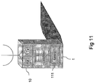
Figure 11 shows a mobile device e with a more detailed view of the transceiver units and showing a battery, and -
Figure 12 shows a repeater node with a more detailed view of the transceiver unit and showing a battery. -
Figure 1 provides a diagram of a simplified network according to an embodiment of the present invention. A mobile device (MD) 1 communicates data to and from acontrol node 7 via a plurality ofrepeater nodes control node 7 form part of a self organising ad-hoc network. When the network is first established each repeater node is operable to identify a parent repeater node that is within a communication range and is disposed between it and thecontrol node 7. When the network is operational, the repeater node transmits upstream data to the parent repeater node. In some embodiments, as will be discussed-below, themobile device 1 is operable to select a repeater node within a communication range and transmit upstream data to that selected repeater node. The selected repeater node then transmits the data it has received from the mobile device to its parent repeater node, and the selected repeater node's parent repeater node will transmit the data to its parent repeater node and so on until the data is finally transmitted to thecontrol node 7. As is shown inFigure 1 , themobile device 1 has selected afirst repeater node 2 to which data is to be transmitted. Thefirst repeater node 2 transmits the data to itsparent repeater node 4, which in turn transmits the data to itsparent repeater node 6 which transmits the data to thecontrol node 7. -
Figure 2 shows an embodiment of the invention in which downstream data is transmitted. The downstream data is transmitted to afirst repeater node 6 which transmits the downstream data to asecond repeater node 5 and athird repeater node 4. The third repeater node then in turn transmits the data to afourth repeater node 3 and afifth repeater node 2. Thefifth repeater node 2 then transmits the data to themobile device 1. In this way the downstream data may be propagated throughout the entire network, regardless of the location of the mobile device. This is an effective way of ensuring that, providing themobile device 1 is in communication range of at least one repeater node the mobile device will always receive the downstream data. - In embodiments of the present invention the communication of data in the network is governed by a time frame.
Figure 3 shows a diagram of atime frame 31 according to which the telecommunications system ofFigures 1 and2 communicate upstream data and downstream data. The time frame lasts for a duration of time T1. Thecontrol node 7 and the plurality ofrepeater nodes time frame 31 which lasts for a period t1. Thefirst repeater node 2 has a corresponding time slot TS1, thesecond repeater node 3 has a corresponding time slot TS2, thethird repeater node 4 has a corresponding time slot TS3 etc. Thecontrol node 7 has a corresponding time slot TS6. Thetime frame 31 includes a reduced power time slot TS7, the purpose of which will be explained shortly. As shown inFigure 3 , each of the time slots TS1 to TS6 include a transmitting half Tx and a receiving half Rx. The telecommunication system is arranged such that each repeater node and thecontrol node 7 will transmit downstream data during the transmitting half Tx of their allocated time slot. Upstream data is transmitted by each repeater node during the receiving half Rx of the allocated time slot of the node to which that repeater node is transmitting the upstream data. So for example, in the network shown inFigures 1 and2 thefirst repeater node 2 will transmit upstream data to thethird repeater node 4 during the receiving half Rx of the time slot allocated to thethird repeater node 4, i.e. time slot TS3. As shown inFigure 2 thefirst repeater node 2 will transmit downstream data during the transmitting half Rx of its allocatedtime slot TS 1. Mobile devices are not allocated a timeslot as they do not transmit data in the downstream direction. - In some embodiments the
time frame 31 is ordered such that the time slots corresponding to parts of the telecommunication system that transmit upstream data directly to each other are arranged to be at a minimal time separation. Thus in the telecommunication system ofFigure 1 , adjacent parts of the network can be arranged to have correspondingly adjacent time slots. Such an arrangement reduces the transmission in the upstream direction. - In one embodiment, timing for the time frame is achieved in accordance with the IEEE 802.15 standard. System timing is provided by the transmission of timing information in the control node time slot TS6. All repeater nodes derive system timing from data transmitted in the control node time slot TS6 received either directly from the
control node 7 or transmitted via other repeater nodes. The period of time over which a time frame occurs may typically be 1 second. - In one example of such a telecommunications network disclosed in our copending UK application number
0707924.7 - As mentioned above, the
time frame 31 includes a reduced power time slot TS7. During this reduced power time slot all therepeater nodes repeater nodes Figure 3 shows the time slot TS7 during which therepeater nodes -
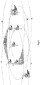
Figure 4 provides a simplified example of thecoverage areas repeater nodes coverage area mobile device 1 when transmitted by the repeater node and received by the repeater node when transmitted by themobile device 1. This area will be determined by factors such as the power and sensitivity of thetransceiver units 11 provided with therepeater nodes transceiver unit 10 provided with themobile device 1. Although not shown inFigure 4 , in some embodiments the coverage area provided by each repeater node is such that it extends across the entire area of the network. - In one embodiment the reduced power pilot signal can be used to provide a handover pilot signal for enabling a mobile device to select a most appropriate repeater node with which to communicate upstream and downstream data. As shown in
Figure 4 themobile device 1 is in afirst coverage area 42 provided by thefirst repeater node 2. When themobile device 1 is in the location shown inFigure 4 , it is solely in thefirst coverage area 42 provided by thefirst repeater node 2. This means there is no choice but to transmit upstream data from the mobile device via thefirst control node 2. However, should the mobile device move to a second location within the indicated hashedarea 47 then themobile device 1 will be within thecoverage area 42 of not only thefirst repeater node 2 but acoverage area 44 provided by asecond repeater node 4 and acoverage area 46 provided by athird repeater node 6. Similarly should the mobile device move to a third location within the indicated cross hatchedarea 48 then themobile device 1 will be within thecoverage area 42 of not only thefirst repeater node 2 but acoverage area 43 provided by afourth repeater node 3 and acoverage area 44 provided by thesecond repeater node 6. If themobile device 1 moves to thesecond location 47 or thethird location 48 then there is more than one potential repeater node to which themobile device 1 can transmit upstream data. - It can be more efficient from the perspective of radio interference, power consumption and data processing to arrange the network so that the
mobile device 1 transmits upstream data to a specific repeater node. Rather than several repeater nodes receiving data from themobile device 1 and transmitting the data onwards across the network, only one repeater node transmits the upstream data received directly from the mobile device. In addition should a network include several mobile devices, without specifying to which repeater node a mobile device is transmitting data the network may become very inefficient due to excessive radio interference. Furthermore, the power with which themobile device 1 transmits data need only be sufficient to ensure that it is received by one (most likely the closest) repeater node. - Therefore, according to an embodiment of the present invention, during the specified pilot signal time slot TS7, all of the
repeater nodes repeater nodes Figure 5 showscoverage areas repeater nodes Figures 4 and5 , as the coverage area of each repeater node is reduced, the size of areas of the network where there is coverage by more than one repeater node is reduced. The hashedarea 47 fromFigure 4 indicating an area of the network within thecoverage area 42 of thefirst repeater node 2, thecoverage area 43 provided by asecond repeater node 3 and thecoverage area 46 provided by thethird repeater node 6 is transposed ontoFigure 5 for reference. It can be seen fromFigure 5 that the location of themobile device 1 is such that during the pilot signal time slot TS7 themobile device 1 is only in thecoverage area 52 provided byrepeater node 2. However, as themobile device 1 is in the hashedarea 47, during the remaining parts of the time frame when the repeater nodes are at full transmitting power, the mobile device will be in the coverage areas of at least three repeater nodes. - As can be seen from
Figure 5 , because the handover pilot signal is transmitted at a reduced power, themobile device 1 will only be within a coverage area provided by a repeater node if the mobile device is relatively near the repeater node. As will be understood this makes determining which repeater node is providing the strongest signal to themobile device 1 much easier to determine. Furthermore, because every repeater node transmits the handover pilot signal at the same time, i.e. during time slot TS7, then themobile device 1 need only be in a handover pilot signal receiving mode for a period of time equivalent to a time period of the time frame t1. As discussed above when the repeater nodes transmit the handover pilot signal, they are operable to include in the handover pilot signal an identifier. The identifier is different for each repeater node and enables the mobile device to determine which repeater nodes have sent the handover pilot signals which it has received. For example inFigure 5 , the mobile device would be able to determine that it has received a handover pilot signal from thefirst repeater node 2. - Once the time slot TS7 is complete and the
mobile device 1 has received all the handover pilot signals from repeater nodes that are in range, themobile device 1 is operable to determine from which repeater node it has received the strongest handover pilot signal and select that repeater node as the repeater node to which themobile device 1 will transmit upstream data and receive downstream data. In the arrangement shown inFigure 5 , themobile device 1 will select thefirst repeater node 2. In some embodiments the radio interface used by the network includes a spread spectrum modulation scheme. By use of a spread spectrum scheme detecting the strongest pilot signal at the mobile device is quite simple to achieve. As will be understood, a property of spread spectrum transmission is that stronger signals will tend to suppress the reception of weaker signals by increasing the level of noise across the spectrum (this is also the case for other modulation schemes). Therefore if a repeater node is for example very close to themobile device 1, the handover pilot signal from that repeater node will not only be stronger but it will also act to suppress the reception of handover pilot signals from other repeater nodes. - In some embodiments the identifier included in the handover pilot signal from each repeater node includes an indication of the time slot which has been allocated to that repeater node of the
time frame 31. Therefore inFigure 1 , themobile device 1 would receive the handover pilot signal from thefirst repeater node 2 and also an indication that thefirst repeater node 2 transmits data during the time slot TS1. By including an indication of the time slot, the mobile device may be operable to reduce power consumption further by powering receiving parts of itstransceiver unit 10 only during the time slot allocated to the selected repeater node and during the time slot TS7 when the handover pilot signals are transmitted. - During a normal operation it would be expected that the
mobile device 1 will move from location to location within the network. Embodiments described above allow for a "seamless handover" from repeater node to repeater node in which themobile device 1 can change the selected repeater node without any active participation required from the repeater nodes or any other part of the network, such as thecontrol node 7. This is because themobile device 1 can move from location to location, determining during the handover pilot signal time slot TS7 the repeater node with which it shares the strongest communication link and then activating the receiving parts of itstransceiver unit 10 during the time slot allocated to the selected repeater node. This is shown inFigure 6 . -
Figure 6 shows the network inFigure 5 but including apath 64 which the mobile device takes through the network. Afirst point 61, asecond point 62 and athird point 63 are shown indicating the location of themobile device 1 during pilot signal timeslots TS7 of thetime frame 31. At thefirst point 61 the mobile device is in the pilot coverage areas of thefirst repeater node 2 and thethird repeater node 4. Therefore during the pilot signal time slot TS7 themobile device 1 will receive pilot signals from both thefirst repeater node 2 and thethird repeater node 4 and will select whichever repeater node provides the strongest signal. At thesecond point 62 the mobile device is not in any handover pilot signal coverage area. In such situations, in some embodiments themobile device 1 will simply continue to use the most recently selected repeater node. In the example shown inFigure 6 this will be either thefirst repeater node 2 or thesecond repeater node 4. At thethird point 63 themobile device 1 is only in the handover pilotsignal coverage area 53 of thesecond repeater node 3 and will therefore select this repeater node. - In one embodiment the reduced power pilot signal can be used to provide a location pilot signal which is transmitted at a reduced power which is typically reduced further than that of the handover pilot signal.
Figure 7 showscoverage areas repeater nodes - As shown in
Figure 7 , the transmission of the location pilot signal at the further reduced power is such that there will be little or no substantial overlap between thecoverage areas repeater nodes transceiver unit 10 of themobile device 1 can receive a location pilot signal transmitted from a repeater node, this indicates that themobile device 1 is within a coverage area provided by a repeater node transmitting at the further reduced power. The system can therefore use this to determine a location of themobile device 1. Thus there are two power settings which correspond to the purpose for which the pilot signal is transmitted, namely the handover pilot signal and the location pilot signal. For example as shown inFigure 8 , therepeater nodes building 81 with each repeater node being placed in a separate room. The repeater nodes may be associated with the specific room in which they are located for example thefirst repeater node 2 could be in akitchen 82. As illustrated inFigure 8 , because the mobile device is within acoverage area 72 of the location pilot signal of thefirst repeater node 2 this indicates that themobile device 1 is in the kitchen. Themobile device 1 may then be operable to send a message to the control node via the repeater nodes indicating that it is presently in the kitchen. Themobile device 1 may make other uses of the location pilot signal for example displaying a message on a display incorporated into the mobile device indicating the location associated with the repeater node which in the example illustrated inFigure 8 might be "KITCHEN". - As can be seen from
Figure 8 , there are areas of thebuilding 81 in which there is no coverage provided by the location pilot signals of any of the repeater nodes. In some embodiments if themobile device 1 were to move from thecoverage area 72 provided by thefirst repeater node 2 to an area where there is no coverage themobile device 1 would be operable to send a message back to the control node indicating the mobile device has moved out of the coverage area of any location pilot signals and the last received location pilot signal was from thefirst repeater node 2. - In one embodiment, the time frame and repeater nodes may be arranged so that the time frame includes both a location pilot signal and a handover pilot signal.
Figure 9 shows an example of a time frame for the network shown inFigures 1 and2 including time slot TS7 during which all the repeater nodes transmit a reduced power handover pilot signal and a time slot TS8 during which all the repeater nodes transmit a location pilot signal at a further reduced power. In this embodiment the mobile device determines from any received handover pilot signals a repeater node with which to communicate data and uses a location pilot signal to determine its location. - In another embodiment, the repeater nodes are arranged so that each of the repeater nodes alternate between transmitting the pilot signal with the second transmission power and transmitting the pilot signal with the third transmission power between consecutive time frames.
Figure 10 shows an example of a time frame for the network shown inFigures 1 and2 including time slot TS7 in afirst time frame 31 during which all the repeater nodes transmit a reduced power handover pilot signal and a second time frame 32 including time slot TS8 during which all the repeater nodes transmit a location pilot signal at a further reduced power. In some cases this embodiment may be preferred over that shown inFigure 9 as there only need be one time slot allocated for the pilot signal. - As shown in
Figure 12 , in some embodiments the repeater nodes are battery powered. Preferably, batteries are used to avoid the additional cost and difficulty of running power cables around a site where the repeater nodes are located. The location determining function of the network would typically require very little battery power such that the battery in the mobile device would typically last in excess of 1 year before needing replacement and the battery in the repeater nodes would typically last in excess of 2 years. This is accomplished by using low power radio devices based on utilisation of the IEEE 802.15.4 standard (to which reference is directed) in both the mobile location device and the base station. - In other example embodiments there is provided a location tracking system operating on at least one radio communication channel and comprising a number of fixed base station transmitter/receivers giving full radio coverage over a site with defined boundaries by means of individual base station synchronised time spaced main beacon signals and limited coverage by means of simultaneously transmitted location beacon signals and operable to transmit both main and location beacon signals under the control of a network co-ordinator unit, and also comprising one or more mobile location devices operating within the coverage area and capable of receiving main and location beacon signals from one or more of the fixed base station transmitters in order to gain synchronism and determine location and in turn transmitting a location signal to identify the position of the respective mobile location device within the coverage area.
- As an alternative, the repeater nodes could be powered from the local AC mains power supply via a power adaptor so as to avoid the need to replace batteries periodically.
- In one embodiment an implementation for the repeater node and mobile device could use a low power radio transceiver with inbuilt microcontroller such as the Chipcon CC2430 IEEE 802.15.4. With this device supporting an implementation with a time frame interval T1 of one second and up to 100 repeater nodes per one second interval, a repeater node would consume approximately 0.5mA and the mobile device approximately 0.2mA. If the repeater nodes operated from two alkaline D cells, having a capacity of 18Ah, they might typically run for three years. If the mobile device operated from two alkaline AA cells, having a capacity of 2Ah, the mobile device might typically run for one year. In one embodiment in which a repeater node uses a Chipcon CC2430, there is used a matching network to convert the balanced antenna interface of the CC2430 to an unbalanced 50 ohm co-axial connector. The CC2430 contains all of the circuitry for running the repeater node software and radio, with data transmission being generated by the same CC2430 hardware.
- Various modifications may be made to the embodiments herein before described. For example, each Mobile Location Device may also be a personal alarm and/or a pager. Also, the Mobile Location Device may provide alarms on movement and/or location based theft detection of equipment.
Claims (24)
- A telecommunications system for communicating data to and from a mobile device (1), the system comprising
a plurality of repeater nodes (2, 3, 4, 5, 6) disposed to form a network, each repeater node (2, 3, 4, 5, 6) having a transceiver unit operable to transmit the data with a first transmission power to one or more others of the repeater nodes (2, 3, 4, 5, 6) within one of a plurality of time slots (TS1, TS2, TS3, TS4, TS5, TS6) of a time frame (T1), each repeater node (2, 3, 4, 5, 6) being allocated one of the time slots (TS1, TS2, TS3, TS4, TS5, TS6) of the time frame (T1) to transmit and receive data to and from the mobile device (1), wherein
each of the repeater nodes (2, 3, 4, 5, 6) is operable to transmit a pilot signal during the same one of the time slots (TS7) of the time frame (T1) as each of the other repeater nodes (2, 3, 4, 5, 6) on a same frequency channel with a second transmission power, the second power being less than the first transmission power, the pilot signal including an identifier of the repeater node (2, 3, 4, 5, 6) which transmitted the pilot signal and
the mobile device (1) is operable
to receive one of the pilot signals transmitted from one of the repeater nodes (2, 3, 4, 5, 6), to detect the identifier included in the pilot signal received from the one repeater node for identifying the location of the mobile device (1), and
to transmit a message to the one repeater node in the one of the time slots of the time frame. - A telecommunications system according to claim 1, wherein
the second transmission power is sufficient to ensure that the mobile device (1) can receive the pilot signal from at least one of the repeater nodes (2, 3, 4, 5, 6)when operating within the network. - A telecommunications system according to claim 1, wherein
the pilot signal is transmitted with a third transmission power, the third transmission power being less than the second transmission power and reduced to the effect that the pilot signal can only be received by the mobile device (1) when in the vicinity of one of the repeater nodes (2, 3, 4, 5, 6). - A telecommunications system according to claim 2 and 3, wherein
each of the repeater nodes (2, 3, 4, 5, 6) alternate between transmitting the pilot signal with the second transmission power and transmitting the pilot signal with the third transmission power. - A telecommunications system according to any of the preceding claims, wherein
the pilot signal transmitted by each repeater node (2, 3, 4, 5, 6) includes an indication of the time slot (TS1, TS2, TS3, TS4, TS5, TS6) of the time frame (T1) used by the repeater node (2, 3, 4, 5, 6) to transmit the data. - A telecommunications system according to any of the preceding claims, wherein
the mobile device (1) is operable to receive the pilot signal from the one repeater node (2, 3, 4, 5, 6) and from the identifier included in the received pilot signal to transmit data to the repeater node (2, 3, 4, 5, 6) identified by the identifier. - A telecommunications system according to any of the preceding claims, wherein
the mobile device (1) is configured to transmit an indication of a location of the mobile device in the message to the one repeater node in the time slot of the time frame (T1) identified by the one repeater node from information in the received pilot signal. - A telecommunications system according to claim 7, wherein
the control node (7) is configured to receive the indication of the location of the mobile device, which is transmitted by the mobile device (1) from the one repeater node, and
to identify the location of the mobile device (1) from the received indication. - A telecommunications system according to any of the preceding claims, wherein
the mobile device (1) is configured
to determine from the identifier included in the received pilot signal and a location associated with the repeater node (2, 3, 4, 5, 6), a relative location of the mobile device (1). - A telecommunications system according to any of the preceding claims, wherein the mobile device (1) is operable to select a repeater node (2, 3, 4, 5, 6) in accordance with the repeater node (2, 3, 4, 5, 6) which the mobile device (1) last received the pilot signal when the mobile device (1) does not receive the pilot signal during the same one of the time slots (TS1, TS2,TS3, TS4, TS5, TS6) during which each of the repeater nodes (2, 3, 4, 5, 6) transmit the pilot signal.
- A method of communicating data to and from a mobile device in a network which includes a plurality of repeater nodes (2, 3, 4, 5, 6), the method comprising
transmitting the data from each of the repeater nodes (2, 3, 4, 5, 6) with a first transmission power to one or more others of the plurality of repeater nodes (2, 3, 4, 5, 6) within one of a plurality of time slots (TS1, TS2, TS3, TS4, TS5, TS6) of a time frame (T1), each repeater node (2, 3, 4, 5, 6) being allocated a different time slot (TS1, TS2, TS3, TS4, TS5, TS6) of the time frame (T1),
transmitting a pilot signal from each repeater node (2, 3, 4, 5, 6) during the same one of the time slots (TS1, TS2, TS3, TS4, TS5, TS6) of the time frame (T1) as each of the other repeater nodes (2, 3, 4, 5, 6) on a same frequency channel with a second transmission power, the second power being less than the first transmission power, the pilot signal including an identifier of the repeater node (2, 3, 4, 5, 6) which transmitted the pilot signal,
receiving, at the mobile device (1), one of the pilot signals transmitted from one of the repeater nodes (1, 2, 3, 4, 5, 6),
detecting the identifier included in the pilot signal received from the one repeater node for identifying the location of the mobile device (1), and
transmitting a message to the one repeater node in the one of the time slots (TS1, TS2, TS3, TS4, TS5, TS6) of the time frame (T1). - A method according to claim 11, wherein
the second transmission power is sufficient to ensure that the mobile device (1) can receive the pilot signal from at least one of the repeater nodes (2, 3, 4, 5, 6) when operating within the network. - A method according to claim 11, wherein
the pilot signal is transmitted with a third transmission power, the third transmission power being less than the second transmission power and reduced to the effect that the pilot signal can only be received by the mobile device (1) when in the vicinity of one of the repeater nodes (2, 3, 4, 5, 6). - A method according to claim 12 and 13, wherein
each of the repeater nodes (2, 3, 4, 5, 6) alternate between transmitting the pilot signal with the second transmission power and transmitting the pilot signal with the third transmission power. - A method according to any of claims 11 to 14, wherein
each pilot signal includes an indication of the time slot (TS1, TS2, TS3, TS4, TS5, TS6) of the time frame (T1) allocated to the repeater node (2, 3, 4, 5, 6) which transmits the pilot signal. - A method accordingly any of claims 11 to 15, wherein
receiving at the mobile device (1) the pilot signal from one of the repeater nodes, includes determining a repeater node (2, 3, 4, 5, 6) to transmit data to, the repeater node identified by the identifier included in the received pilot signal. - A method according to any of claims 11 to 16, including
receiving at the mobile device (1) the pilot signal from one of the repeater nodes (2, 3, 4, 5, 6), and
determining from the identifier included in the received pilot signal and a location associated with the one repeater node (2, 3, 4, 5, 6), a relative location of the mobile device (1). - A method according to claim 11 to 17, wherein when the mobile device (1) does not receive the pilot signal during the same one of the time slots (TS1, TS2, TS3, TS4, TS5, TS6) during which each of the repeater nodes (2, 3, 4, 5, 6) transmit the pilot signal, the mobile device selects a repeater node in accordance with the repeater node (2, 3, 4, 5, 6) which the mobile device (1) last received the pilot signal.
- A method according to claims 11 to 18, comprising
transmitting, from the mobile device (1), an indication of a location of the mobile device in the message to the one repeater node in the time slot of the time frame (T1) identified by the one repeater node from information in the received pilot signal. - A method according to claim 19, comprising
receiving at the control node (7) the indication of the location of the mobile device, which is transmitted by the mobile device from the one repeater node, and
identifying the location of the mobile device (1) from the received indication. - A repeater node (2, 3, 4, 5, 6) for communicating data to a mobile device (1) in a system including one or more other repeater nodes (2, 3, 4, 5, 6) and a control node (7) the repeater node comprising
a transceiver unit operable to transmit and receive data to or from one or more others of a plurality of repeater nodes (2, 3, 4, 5, 6) and a mobile device (1) within one of a plurality of time slots (2, 3, 4, 5, 6) of a time frame (T1), wherein
the transceiver unit is operable to transmit the data with a first transmission power to one or more of the repeater nodes (2, 3, 4, 5, 6) within the one of a plurality of time slots (TS1, TS2, TS3, TS4, TS5, TS6) of a time frame (T1),, and
the transceiver unit is operable to transmit a pilot signal during a second time slot of the time frame (T1) and during a same time slot (TS7) of the time frame as each of the other repeater nodes on a same frequency channel with a second transmission power, the second power being less than the first transmission power, the pilot signal including an identifier of the repeater node (2, 3, 4, 5, 6) which transmitted the pilot signal, and
the transceiver unit is operable to receive a message from the mobile device (1) within the one of the time slots of the a time frame (T1), the message indicating a location of the mobile device (1). - A mobile device (1) for communicating data in a system including a plurality of repeater nodes (2, 3, 4, 5, 7) and a control node (7), the mobile device (1) comprising
a transceiver unit operable to transmit and receive data to or from one or more of repeater nodes (2, 3, 4, 5, 6), wherein
the transceiver unit is operable to transmit the data to one of the repeater nodes (2, 3, 4, 5, 6) within one of a plurality of time slots (TS1, TS2, TS3, TS4, TS5, TS6) of a time frame (T1), wherein the plurality of repeater nodes (2, 3, 4, 5, 6) are each operable to transmit a pilot signal during a second time slot of the time frame which is during the same time slot of the time frame as each of the other repeater nodes (2, 3, 4, 5, 6) on a same frequency channel, and
the transceiver unit is operable to receive a pilot signal from a repeater node (2, 3, 4, 5, 6) during the second time slot of the time frame (T1), the pilot signal including an identifier of the repeater node (2, 3, 4, 5, 6) which transmitted the pilot signal, and the mobile device (1) is operable
to detect the identifier included in the pilot signal received from the one repeater node for identifying the location of the mobile device (1), and
the transceiver unit is operable
to transmit a message to the one repeater node in the one of the time slots of the time frame (T1). - A mobile device (1) according to claim 22, wherein
the transceiver unit is operable to transmit the message to the one repeater node within one of the plurality of time slots (TS1, TS2, TS3, TS4, TS5, TS6), the message indicating a location of the mobile device (1), the location of the mobile device (1) being determined based on the identifier included in the received pilot signal. - A mobile device (1) according to claims 22 and 23, wherein
the mobile device (1) is configured to transmit an indication of a location of the mobile device in the message to the one repeater node in the one of the plurality of time slots (TS1, TS2, TS3, TS4, TS5, TS6) of the time frame (T1), wherein the one of the plurality of time slots is identified from information in the received pilot signal.
Applications Claiming Priority (3)
| Application Number | Priority Date | Filing Date | Title |
|---|---|---|---|
| GB0614074A GB2440189B (en) | 2006-07-14 | 2006-07-14 | Location tracking systems |
| GB0709428A GB2449278B (en) | 2007-05-16 | 2007-05-16 | Telecommunications system and method |
| PCT/GB2007/002663 WO2008007129A1 (en) | 2006-07-14 | 2007-07-13 | Telecommunications system and method |
Publications (2)
| Publication Number | Publication Date |
|---|---|
| EP2041890A1 EP2041890A1 (en) | 2009-04-01 |
| EP2041890B1 true EP2041890B1 (en) | 2017-03-01 |
Family
ID=38441560
Family Applications (1)
| Application Number | Title | Priority Date | Filing Date |
|---|---|---|---|
| EP07766235.1A Active EP2041890B1 (en) | 2006-07-14 | 2007-07-13 | Telecommunications system and method |
Country Status (6)
| Country | Link |
|---|---|
| US (1) | US8885540B2 (en) |
| EP (1) | EP2041890B1 (en) |
| AU (1) | AU2007274018B2 (en) |
| CA (1) | CA2657573C (en) |
| ES (1) | ES2624807T3 (en) |
| WO (1) | WO2008007129A1 (en) |
Families Citing this family (6)
| Publication number | Priority date | Publication date | Assignee | Title |
|---|---|---|---|---|
| US9083434B2 (en) * | 2011-09-21 | 2015-07-14 | Telefonaktiebolaget L M Ericsson (Publ) | System and method for operating a repeater |
| US20140300477A1 (en) | 2012-09-25 | 2014-10-09 | Woodstream Corporation | Wireless notification systems and methods for electronic rodent traps |
| EP3449677B1 (en) * | 2016-04-28 | 2021-12-29 | Sony Group Corporation | Transmit power of pilot signals |
| US10784952B2 (en) * | 2018-11-02 | 2020-09-22 | Wistron Neweb Corporation | Repeater |
| JP2022113422A (en) * | 2021-01-25 | 2022-08-04 | シャープ株式会社 | Repeater reception cycle setting method, communication system, and repeater |
| US11589188B1 (en) | 2021-05-27 | 2023-02-21 | T-Mobile Usa, Inc. | Device-based timely emergency call routing |
Family Cites Families (17)
| Publication number | Priority date | Publication date | Assignee | Title |
|---|---|---|---|---|
| JP2682847B2 (en) * | 1988-07-21 | 1997-11-26 | 株式会社日立製作所 | Relay loop bypass method for packet switching network |
| US5179559A (en) * | 1990-07-27 | 1993-01-12 | Motorola, Inc. | Handoff method for a cellular system |
| US5506864A (en) * | 1990-12-05 | 1996-04-09 | Interdigital Technology Corporation | CDMA communications and geolocation system and method |
| US5263177A (en) * | 1991-01-22 | 1993-11-16 | Motorola, Inc. | Modified simulcast communication system |
| US5265150A (en) | 1991-01-30 | 1993-11-23 | At&T Bell Laboratories | Automatically configuring wireless PBX system |
| US5392287A (en) * | 1992-03-05 | 1995-02-21 | Qualcomm Incorporated | Apparatus and method for reducing power consumption in a mobile communications receiver |
| FR2715013B1 (en) * | 1994-01-12 | 1996-03-29 | Nortel Matra Cellular | Method for locating a mobile cellular radio station, and equipment for implementing the method. |
| JPH11205845A (en) * | 1998-01-14 | 1999-07-30 | Locus:Kk | Position specifying system |
| CA2397430A1 (en) * | 2000-01-14 | 2001-07-19 | Breck W. Lovinggood | Repeaters for wireless communication systems |
| US7099384B1 (en) * | 2000-09-01 | 2006-08-29 | Qualcomm, Inc. | Method and apparatus for time-division power assignments in a wireless communication system |
| US7068704B1 (en) * | 2001-09-26 | 2006-06-27 | Itt Manufacturing Enterpprises, Inc. | Embedded chirp signal for position determination in cellular communication systems |
| US20030157943A1 (en) * | 2002-01-29 | 2003-08-21 | John Sabat | Method and apparatus for auxiliary pilot signal for mobile phone location |
| US7050758B2 (en) | 2002-02-28 | 2006-05-23 | Nortel Networks Limited | Self-configuring repeater system and method |
| CN1192650C (en) * | 2002-04-26 | 2005-03-09 | 华为技术有限公司 | Directly amplifying station and its mobile station locating method |
| US6961367B2 (en) * | 2003-02-24 | 2005-11-01 | Qualcomm, Incorporated | Forward link repeater frequency watermarking scheme |
| WO2004095733A2 (en) | 2003-04-17 | 2004-11-04 | Qualcomm Incorporated | Method and apparatus for determining repeater use in wireless communications |
| DE102004062034A1 (en) | 2004-12-23 | 2006-07-13 | Robert Bosch Gmbh | Repeater node for a network |
-
2007
- 2007-07-13 AU AU2007274018A patent/AU2007274018B2/en active Active
- 2007-07-13 ES ES07766235.1T patent/ES2624807T3/en active Active
- 2007-07-13 WO PCT/GB2007/002663 patent/WO2008007129A1/en active Application Filing
- 2007-07-13 CA CA2657573A patent/CA2657573C/en active Active
- 2007-07-13 EP EP07766235.1A patent/EP2041890B1/en active Active
- 2007-07-13 US US12/373,043 patent/US8885540B2/en not_active Expired - Fee Related
Non-Patent Citations (1)
| Title |
|---|
| None * |
Also Published As
| Publication number | Publication date |
|---|---|
| US8885540B2 (en) | 2014-11-11 |
| AU2007274018A1 (en) | 2008-01-17 |
| CA2657573C (en) | 2015-01-27 |
| WO2008007129A1 (en) | 2008-01-17 |
| AU2007274018B2 (en) | 2011-02-03 |
| US20100034132A1 (en) | 2010-02-11 |
| EP2041890A1 (en) | 2009-04-01 |
| CA2657573A1 (en) | 2008-01-17 |
| ES2624807T3 (en) | 2017-07-17 |
Similar Documents
| Publication | Publication Date | Title |
|---|---|---|
| US6370356B2 (en) | Apparatus and method of providing a mobile communication system | |
| US8005050B2 (en) | Localization of a mobile device in distributed antenna communications system | |
| EP1627537B1 (en) | Method and apparatus for channel sharing between multiple communication systems | |
| JP2701626B2 (en) | Wireless connection method | |
| EP2157808B1 (en) | Adaptive management method for wireless transfer network containing base station and wireless relay stations | |
| CN101388701B (en) | Customer data receiving/transmitting method, apparatus and distributed intelligent antenna system | |
| EP2041890B1 (en) | Telecommunications system and method | |
| US20090040985A1 (en) | Method and apparatus for supporting ad-hoc networking over umts protocol | |
| JPH03104428A (en) | System for constituting mobile communication radio control channel | |
| US6941140B2 (en) | Allocation of channels to radio transceivers | |
| JP2002533692A (en) | Positioning beacon | |
| CN102450076A (en) | Extended coordinated multipoint cells to mitigate inter-comp-cell downlink interference | |
| EP2156576B1 (en) | Telecommunications system and method | |
| KR100291613B1 (en) | Master and slaves for use in telecommunication systems and this telecommunication system | |
| AU722795B2 (en) | Method of improving connection quality and system capacity, and a cellular radio system | |
| MXPA05005050A (en) | Fast reacquisition after long sleep in slotted mode operation. | |
| CN103249053A (en) | Dispatching and service configuration method and device of user equipment | |
| CN101959205A (en) | Uplink measurement method and system for relay network | |
| KR101041135B1 (en) | Method for keeping network synchronization |
Legal Events
| Date | Code | Title | Description |
|---|---|---|---|
| PUAI | Public reference made under article 153(3) epc to a published international application that has entered the european phase |
Free format text: ORIGINAL CODE: 0009012 |
|
| 17P | Request for examination filed |
Effective date: 20090129 |
|
| AK | Designated contracting states |
Kind code of ref document: A1 Designated state(s): AT BE BG CH CY CZ DE DK EE ES FI FR GB GR HU IE IS IT LI LT LU LV MC MT NL PL PT RO SE SI SK TR |
|
| AX | Request for extension of the european patent |
Extension state: AL BA HR MK RS |
|
| DAX | Request for extension of the european patent (deleted) | ||
| 17Q | First examination report despatched |
Effective date: 20120801 |
|
| REG | Reference to a national code |
Ref country code: DE Ref legal event code: R079 Ref document number: 602007049966 Country of ref document: DE Free format text: PREVIOUS MAIN CLASS: H04B0007260000 Ipc: H04B0007155000 |
|
| GRAP | Despatch of communication of intention to grant a patent |
Free format text: ORIGINAL CODE: EPIDOSNIGR1 |
|
| RIC1 | Information provided on ipc code assigned before grant |
Ipc: H04B 7/155 20060101AFI20160826BHEP |
|
| INTG | Intention to grant announced |
Effective date: 20160919 |
|
| STAA | Information on the status of an ep patent application or granted ep patent |
Free format text: STATUS: GRANT OF PATENT IS INTENDED |
|
| GRAS | Grant fee paid |
Free format text: ORIGINAL CODE: EPIDOSNIGR3 |
|
| GRAA | (expected) grant |
Free format text: ORIGINAL CODE: 0009210 |
|
| STAA | Information on the status of an ep patent application or granted ep patent |
Free format text: STATUS: THE PATENT HAS BEEN GRANTED |
|
| AK | Designated contracting states |
Kind code of ref document: B1 Designated state(s): AT BE BG CH CY CZ DE DK EE ES FI FR GB GR HU IE IS IT LI LT LU LV MC MT NL PL PT RO SE SI SK TR |
|
| REG | Reference to a national code |
Ref country code: GB Ref legal event code: FG4D |
|
| REG | Reference to a national code |
Ref country code: CH Ref legal event code: EP Ref country code: AT Ref legal event code: REF Ref document number: 872428 Country of ref document: AT Kind code of ref document: T Effective date: 20170315 |
|
| REG | Reference to a national code |
Ref country code: IE Ref legal event code: FG4D |
|
| REG | Reference to a national code |
Ref country code: DE Ref legal event code: R096 Ref document number: 602007049966 Country of ref document: DE |
|
| REG | Reference to a national code |
Ref country code: NL Ref legal event code: FP |
|
| REG | Reference to a national code |
Ref country code: DK Ref legal event code: T3 Effective date: 20170523 |
|
| REG | Reference to a national code |
Ref country code: SE Ref legal event code: TRGR |
|
| REG | Reference to a national code |
Ref country code: FR Ref legal event code: PLFP Year of fee payment: 11 |
|
| REG | Reference to a national code |
Ref country code: LT Ref legal event code: MG4D |
|
| REG | Reference to a national code |
Ref country code: AT Ref legal event code: MK05 Ref document number: 872428 Country of ref document: AT Kind code of ref document: T Effective date: 20170301 |
|
| REG | Reference to a national code |
Ref country code: ES Ref legal event code: FG2A Ref document number: 2624807 Country of ref document: ES Kind code of ref document: T3 Effective date: 20170717 |
|
| PG25 | Lapsed in a contracting state [announced via postgrant information from national office to epo] |
Ref country code: FI Free format text: LAPSE BECAUSE OF FAILURE TO SUBMIT A TRANSLATION OF THE DESCRIPTION OR TO PAY THE FEE WITHIN THE PRESCRIBED TIME-LIMIT Effective date: 20170301 Ref country code: LT Free format text: LAPSE BECAUSE OF FAILURE TO SUBMIT A TRANSLATION OF THE DESCRIPTION OR TO PAY THE FEE WITHIN THE PRESCRIBED TIME-LIMIT Effective date: 20170301 Ref country code: GR Free format text: LAPSE BECAUSE OF FAILURE TO SUBMIT A TRANSLATION OF THE DESCRIPTION OR TO PAY THE FEE WITHIN THE PRESCRIBED TIME-LIMIT Effective date: 20170602 |
|
| PG25 | Lapsed in a contracting state [announced via postgrant information from national office to epo] |
Ref country code: AT Free format text: LAPSE BECAUSE OF FAILURE TO SUBMIT A TRANSLATION OF THE DESCRIPTION OR TO PAY THE FEE WITHIN THE PRESCRIBED TIME-LIMIT Effective date: 20170301 Ref country code: LV Free format text: LAPSE BECAUSE OF FAILURE TO SUBMIT A TRANSLATION OF THE DESCRIPTION OR TO PAY THE FEE WITHIN THE PRESCRIBED TIME-LIMIT Effective date: 20170301 Ref country code: BG Free format text: LAPSE BECAUSE OF FAILURE TO SUBMIT A TRANSLATION OF THE DESCRIPTION OR TO PAY THE FEE WITHIN THE PRESCRIBED TIME-LIMIT Effective date: 20170601 |
|
| PG25 | Lapsed in a contracting state [announced via postgrant information from national office to epo] |
Ref country code: CZ Free format text: LAPSE BECAUSE OF FAILURE TO SUBMIT A TRANSLATION OF THE DESCRIPTION OR TO PAY THE FEE WITHIN THE PRESCRIBED TIME-LIMIT Effective date: 20170301 Ref country code: SK Free format text: LAPSE BECAUSE OF FAILURE TO SUBMIT A TRANSLATION OF THE DESCRIPTION OR TO PAY THE FEE WITHIN THE PRESCRIBED TIME-LIMIT Effective date: 20170301 Ref country code: EE Free format text: LAPSE BECAUSE OF FAILURE TO SUBMIT A TRANSLATION OF THE DESCRIPTION OR TO PAY THE FEE WITHIN THE PRESCRIBED TIME-LIMIT Effective date: 20170301 Ref country code: RO Free format text: LAPSE BECAUSE OF FAILURE TO SUBMIT A TRANSLATION OF THE DESCRIPTION OR TO PAY THE FEE WITHIN THE PRESCRIBED TIME-LIMIT Effective date: 20170301 |
|
| PG25 | Lapsed in a contracting state [announced via postgrant information from national office to epo] |
Ref country code: PL Free format text: LAPSE BECAUSE OF FAILURE TO SUBMIT A TRANSLATION OF THE DESCRIPTION OR TO PAY THE FEE WITHIN THE PRESCRIBED TIME-LIMIT Effective date: 20170301 Ref country code: PT Free format text: LAPSE BECAUSE OF FAILURE TO SUBMIT A TRANSLATION OF THE DESCRIPTION OR TO PAY THE FEE WITHIN THE PRESCRIBED TIME-LIMIT Effective date: 20170703 Ref country code: IS Free format text: LAPSE BECAUSE OF FAILURE TO SUBMIT A TRANSLATION OF THE DESCRIPTION OR TO PAY THE FEE WITHIN THE PRESCRIBED TIME-LIMIT Effective date: 20170701 |
|
| REG | Reference to a national code |
Ref country code: DE Ref legal event code: R097 Ref document number: 602007049966 Country of ref document: DE |
|
| PLBE | No opposition filed within time limit |
Free format text: ORIGINAL CODE: 0009261 |
|
| STAA | Information on the status of an ep patent application or granted ep patent |
Free format text: STATUS: NO OPPOSITION FILED WITHIN TIME LIMIT |
|
| 26N | No opposition filed |
Effective date: 20171204 |
|
| PG25 | Lapsed in a contracting state [announced via postgrant information from national office to epo] |
Ref country code: SI Free format text: LAPSE BECAUSE OF FAILURE TO SUBMIT A TRANSLATION OF THE DESCRIPTION OR TO PAY THE FEE WITHIN THE PRESCRIBED TIME-LIMIT Effective date: 20170301 |
|
| REG | Reference to a national code |
Ref country code: FR Ref legal event code: PLFP Year of fee payment: 12 |
|
| REG | Reference to a national code |
Ref country code: BE Ref legal event code: MM Effective date: 20170731 |
|
| PG25 | Lapsed in a contracting state [announced via postgrant information from national office to epo] |
Ref country code: LU Free format text: LAPSE BECAUSE OF NON-PAYMENT OF DUE FEES Effective date: 20170713 |
|
| PG25 | Lapsed in a contracting state [announced via postgrant information from national office to epo] |
Ref country code: BE Free format text: LAPSE BECAUSE OF NON-PAYMENT OF DUE FEES Effective date: 20170731 |
|
| PG25 | Lapsed in a contracting state [announced via postgrant information from national office to epo] |
Ref country code: MT Free format text: LAPSE BECAUSE OF NON-PAYMENT OF DUE FEES Effective date: 20170713 |
|
| PG25 | Lapsed in a contracting state [announced via postgrant information from national office to epo] |
Ref country code: MC Free format text: LAPSE BECAUSE OF FAILURE TO SUBMIT A TRANSLATION OF THE DESCRIPTION OR TO PAY THE FEE WITHIN THE PRESCRIBED TIME-LIMIT Effective date: 20170301 Ref country code: HU Free format text: LAPSE BECAUSE OF FAILURE TO SUBMIT A TRANSLATION OF THE DESCRIPTION OR TO PAY THE FEE WITHIN THE PRESCRIBED TIME-LIMIT; INVALID AB INITIO Effective date: 20070713 |
|
| PG25 | Lapsed in a contracting state [announced via postgrant information from national office to epo] |
Ref country code: CY Free format text: LAPSE BECAUSE OF NON-PAYMENT OF DUE FEES Effective date: 20170301 |
|
| PG25 | Lapsed in a contracting state [announced via postgrant information from national office to epo] |
Ref country code: TR Free format text: LAPSE BECAUSE OF FAILURE TO SUBMIT A TRANSLATION OF THE DESCRIPTION OR TO PAY THE FEE WITHIN THE PRESCRIBED TIME-LIMIT Effective date: 20170301 |
|
| REG | Reference to a national code |
Ref country code: DE Ref legal event code: R082 Ref document number: 602007049966 Country of ref document: DE Representative=s name: D YOUNG & CO LLP, DE |
|
| PGFP | Annual fee paid to national office [announced via postgrant information from national office to epo] |
Ref country code: DK Payment date: 20230629 Year of fee payment: 17 |
|
| PGFP | Annual fee paid to national office [announced via postgrant information from national office to epo] |
Ref country code: NL Payment date: 20230720 Year of fee payment: 17 |
|
| PGFP | Annual fee paid to national office [announced via postgrant information from national office to epo] |
Ref country code: IT Payment date: 20230717 Year of fee payment: 17 Ref country code: IE Payment date: 20230727 Year of fee payment: 17 Ref country code: GB Payment date: 20230718 Year of fee payment: 17 Ref country code: ES Payment date: 20230807 Year of fee payment: 17 Ref country code: CH Payment date: 20230801 Year of fee payment: 17 |
|
| PGFP | Annual fee paid to national office [announced via postgrant information from national office to epo] |
Ref country code: SE Payment date: 20230713 Year of fee payment: 17 Ref country code: FR Payment date: 20230710 Year of fee payment: 17 Ref country code: DE Payment date: 20230717 Year of fee payment: 17 |