EP2041850B1 - Pluggable device combination for protecting against surges - Google Patents
Pluggable device combination for protecting against surges Download PDFInfo
- Publication number
- EP2041850B1 EP2041850B1 EP07729611A EP07729611A EP2041850B1 EP 2041850 B1 EP2041850 B1 EP 2041850B1 EP 07729611 A EP07729611 A EP 07729611A EP 07729611 A EP07729611 A EP 07729611A EP 2041850 B1 EP2041850 B1 EP 2041850B1
- Authority
- EP
- European Patent Office
- Prior art keywords
- plug
- module
- shaped
- hinge joint
- combination
- Prior art date
- Legal status (The legal status is an assumption and is not a legal conclusion. Google has not performed a legal analysis and makes no representation as to the accuracy of the status listed.)
- Active
Links
Images
Classifications
-
- H—ELECTRICITY
- H01—ELECTRIC ELEMENTS
- H01T—SPARK GAPS; OVERVOLTAGE ARRESTERS USING SPARK GAPS; SPARKING PLUGS; CORONA DEVICES; GENERATING IONS TO BE INTRODUCED INTO NON-ENCLOSED GASES
- H01T4/00—Overvoltage arresters using spark gaps
- H01T4/06—Mounting arrangements for a plurality of overvoltage arresters
-
- H—ELECTRICITY
- H01—ELECTRIC ELEMENTS
- H01R—ELECTRICALLY-CONDUCTIVE CONNECTIONS; STRUCTURAL ASSOCIATIONS OF A PLURALITY OF MUTUALLY-INSULATED ELECTRICAL CONNECTING ELEMENTS; COUPLING DEVICES; CURRENT COLLECTORS
- H01R13/00—Details of coupling devices of the kinds covered by groups H01R12/70 or H01R24/00 - H01R33/00
- H01R13/46—Bases; Cases
- H01R13/502—Bases; Cases composed of different pieces
- H01R13/506—Bases; Cases composed of different pieces assembled by snap action of the parts
-
- H—ELECTRICITY
- H01—ELECTRIC ELEMENTS
- H01R—ELECTRICALLY-CONDUCTIVE CONNECTIONS; STRUCTURAL ASSOCIATIONS OF A PLURALITY OF MUTUALLY-INSULATED ELECTRICAL CONNECTING ELEMENTS; COUPLING DEVICES; CURRENT COLLECTORS
- H01R13/00—Details of coupling devices of the kinds covered by groups H01R12/70 or H01R24/00 - H01R33/00
- H01R13/66—Structural association with built-in electrical component
- H01R13/665—Structural association with built-in electrical component with built-in electronic circuit
- H01R13/6666—Structural association with built-in electrical component with built-in electronic circuit with built-in overvoltage protection
-
- H—ELECTRICITY
- H01—ELECTRIC ELEMENTS
- H01R—ELECTRICALLY-CONDUCTIVE CONNECTIONS; STRUCTURAL ASSOCIATIONS OF A PLURALITY OF MUTUALLY-INSULATED ELECTRICAL CONNECTING ELEMENTS; COUPLING DEVICES; CURRENT COLLECTORS
- H01R9/00—Structural associations of a plurality of mutually-insulated electrical connecting elements, e.g. terminal strips or terminal blocks; Terminals or binding posts mounted upon a base or in a case; Bases therefor
- H01R9/22—Bases, e.g. strip, block, panel
- H01R9/24—Terminal blocks
- H01R9/2425—Structural association with built-in components
- H01R9/2441—Structural association with built-in components with built-in overvoltage protection
-
- H—ELECTRICITY
- H01—ELECTRIC ELEMENTS
- H01T—SPARK GAPS; OVERVOLTAGE ARRESTERS USING SPARK GAPS; SPARKING PLUGS; CORONA DEVICES; GENERATING IONS TO BE INTRODUCED INTO NON-ENCLOSED GASES
- H01T1/00—Details of spark gaps
- H01T1/12—Means structurally associated with spark gap for recording operation thereof
Definitions
- the invention relates to a pluggable device combination for protection against overvoltage, comprising a socket-like U-shaped lower part for receiving at least one, an overvoltage protection element receiving plug-in module, wherein acting between the plug-in module and the base-like base locking means are provided which on opposite end sides of the plug-in module to a lower Preload hinge hinge formed locking lugs comprise, which each engage in an associated latching recess on the base part, wherein the latching connection can be canceled by pressure on the hinge joint on the end faces of the plug-in module, according to the preamble of claim 1.
- Overvoltage protection devices of the prior art are in many cases designed as pluggable device combinations comprising a lower part and a plug-in module.
- the lower part of terminals for contacting the electrical conductors are arranged and appropriate receptacles for the plug-in module to be used. Furthermore, the lower part receives elements that surround one or more plug contacts of the plug-in module, so that the desired mechanical and electrical contact and the corresponding hold of the plug-in module is provided in the lower part.
- the plug-in module contains the actual overvoltage protection elements, e.g. Spark gaps, varistors, gas arresters or similar.
- the lower parts are formed in many cases as a U-shaped body, wherein the open legs of the U-shaped body laterally engage around the plug-in module and wherein the plug-in module rests on the connecting leg of the U-shaped part. Furthermore, the lower part has on its mounting side receiving elements that allow a so-called DIN rail mounting.
- the removed plug-in module can then be examined outside the electrical system with the aid of special test equipment and optionally replaced or reused.
- the DE 36 39 533 C2 , the DE 295 19 313 U1 , the DE 100 01 667 C1 and the DE 20 2004 006 227 U1 directed.
- the plug-in modules can be removed without tools or only with the aid of a tool. If no additional measures are provided, there is the danger that under the influence of the electrodynamic force effects during the surge current operation, it may come to an unwanted jumping out of the plug-in module from the lower part, so that a proper overall function of the device is not given without further protective measures.
- WO 95/12905 a solution is previously known, which also comprises a U-shaped lower part for receiving at least one, an overvoltage protection element receiving plug-in module and wherein acting between the plug-in module and the base-like base locking means are provided.
- an overvoltage protection element receiving plug-in module and wherein acting between the plug-in module and the base-like base locking means are provided.
- At the opposite end faces of the plug-in module formed on a hinge joint locking lugs are present, which engage in each case in an associated latching recess on the plug-in module, wherein the latching connection by pressure on the hinge joint, which acts on the end faces of the plug-in module, can be canceled.
- the hinge joint of the previously known solution is located at the bottom of the plug-in module and the pressure surface is located by a small amount above the locking lugs on the end faces of the module.
- the pressure surfaces of this prior art are very small and the necessary recesses or depressions in the lower part is a very disadvantageous, heavy gripping the plug-in module required. Due to the arrangement of the actual hinge on the lower side of the plug-in module, a very large pressure path is required to cancel the latching.
- the latching surface of the locking lug on the plug-in module and the recess in the lower part are parallel, so that there is the possibility of unwanted cancellation of the latching when vibration or vibration.
- pluggable device combination for protection against overvoltage, comprising a socket-like U-shaped lower part for receiving at least one, an overvoltage protection element receiving plug-in module, wherein a constructive and effective side improvement between the plug-in module and the base-like base acting latching means to be created.
- the pluggable device combination for protection against overvoltages comprising a base-like U-shaped lower part for receiving at least one, an overvoltage protection element receiving plug-in module has a special Rastschaustex in which the respective hinge joint is located in the transition region between the top and the respective end face of the plug-in module.
- the hinge joint is in each case in a directed to the base-like base actuating surface, which is designed much larger compared to the prior art.
- a hook-shaped locking lug is formed, the locking surface forms an angle of less than 90 ° with the actuating surface.
- the U-legs of the lower part each have a hook-shaped, undercut latching recess, which is designed to be complementary to the latching lug.
- the unlocked plug-in module can be easily pulled out of the U-shaped lower part by the very large extent of the actuating surface.
- the latching surface on the plug-in part and the surface on the recess in the lower part have opposite directions obliquely extending surfaces, so that the latching nose and the return interlock each other and thus a self-locking the latching connection is given.
- the surfaces of the respective actuating surface have a structuring.
- the lower ends of the plug-in module have converging, front side sections running on each other, so that an easier insertion of the module can be done even under unfavorable installation conditions.
- the inner sides of the legs of the U-shaped base-like base have a shape complementary to the conical end portions.
- the hinge joint In the region of its point of articulation, the hinge joint has a weakening section which improves the operability and which can be formed as a groove on the inside of the hinge.
- the hook-shaped latching nose has a wedge-shaped sliding surface.
- the wedge angle of the sliding surface is less than or equal to the locking surface angle, i. the angle between the locking surface and the actuating surface.
- a part of the recess forming legs of the lower part beyond a radius of curvature is formed to facilitate the insertion of the module in the lower part.
- the actuating surfaces are freely accessible even in the plugged, latched state of the plug-in module.
- the provision of any depressions or recesses on the lower part is not required.
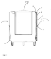
- Fig. 1 a side view of a plug-in module with partially broken representation in the region of the actuating surface and the latching lug;
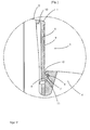
- Fig. 2 a detailed view of the hinge joint and the latching nose and the latching recess in the latched state, ie when the plug-in module is completely and correctly in the lower part, and
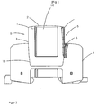
- Fig. 3 an overall view of the located in the lower part, fully inserted and latched plug-in module.
- the plug-in module 14 according to the figurative representations consists of a housing, wherein the housing inside surge protection elements, e.g. Picking up varistors. In the lower part known plug contacts and a guide or coding pin are formed.
- surge protection elements e.g. Picking up varistors.
- plug contacts and a guide or coding pin are formed.
- the end faces 3 of the plug-in module 14 have actuating surfaces 5, which merge into a hinge joint 1.
- the respective hinge joint is located in the region of the upper side 2 of the plug-in module 14.
- a hook-shaped locking lug 6 is present.
- the locking surface 7 of the locking lug 6 closes with the surface of the actuating surface an angle of preferably less than 90 °.
- the actuating surface 5 has a surface structuring 9.
- a hinge inside groove is formed as a targeted weakening in the region of the hinge joint 1.
- the hook-shaped locking lug 6 engages in a recess 8 of the lower part 4, when the plug-in module 14 is in the correct, inserted state.
- the hook-shaped latching nose 6 has a wedge-shaped sliding surface 11. Likewise, a rounding radius 12 is formed in the region of the recess 8.
- the hinge joint 1 is biased, for example due to a suitable selection of a plastic material of the corresponding housing part or a housing cap, which comprises the hinge joint 1, the locking surface 5 and the locking lug 6 as an integral element.
- Fig. 3 has the plug-in module 14 on its underside conical end side portions in order to facilitate insertion and a secure fit in the corresponding complementarily formed U-shaped base 4 to effect.
- the representation after Fig. 3 makes it clear, in particular, that the respective actuating surfaces 5 are freely accessible even in the inserted and latched state of the plug-in module 14 in order to be able to transfer sufficient forces by releasing the latching connection by lateral pressure to pull the plug-in module 14 from the U-shaped base-like base.
Abstract
Description
Die Erfindung betrifft eine steckbare Gerätekombination zum Schutz vor Überspannungen, umfassend ein sockelartiges U-förmiges Unterteil zur Aufnahme mindestens eines, ein Überspannungsschutzelement aufnehmendes Steckmodul, wobei zwischen dem Steckmodul und dem sockelartigen Unterteil wirkende Rastmittel vorgesehen sind, die an gegenüberliegenden Stirnseiten des Steckmoduls an einem unter Vorspannung stehenden Scharniergelenk ausgebildete Rastnasen umfassen, welche jeweils in eine zugehörige Rastausnehmung am Sockelteil eingreifen, wobei die Rastverbindung durch Druck auf das Scharniergelenk an den Stirnseiten des Steckmoduls aufhebbar ist, gemäß Oberbegriff des Patentanspruchs 1.The invention relates to a pluggable device combination for protection against overvoltage, comprising a socket-like U-shaped lower part for receiving at least one, an overvoltage protection element receiving plug-in module, wherein acting between the plug-in module and the base-like base locking means are provided which on opposite end sides of the plug-in module to a lower Preload hinge hinge formed locking lugs comprise, which each engage in an associated latching recess on the base part, wherein the latching connection can be canceled by pressure on the hinge joint on the end faces of the plug-in module, according to the preamble of
Überspannungsschutzgeräte des Standes der Technik werden in vielen Fällen als steckbare Gerätekombinationen, umfassend ein Unterteil und ein Steckmodul, ausgeführt.Overvoltage protection devices of the prior art are in many cases designed as pluggable device combinations comprising a lower part and a plug-in module.
Im Unterteil sind Anschlussklemmen zur Kontaktierung der elektrischen Leiter angeordnet sowie entsprechende Aufnahmen für das einzusetzende Steckmodul vorhanden. Weiterhin nimmt das Unterteil Elemente auf, die einen oder mehrere Steckkontakte des Steckmoduls umgreifen, so dass der gewünschte mechanische und elektrische Kontakt sowie der entsprechende Halt des Steckmoduls im Unterteil gegeben ist.In the lower part of terminals for contacting the electrical conductors are arranged and appropriate receptacles for the plug-in module to be used. Furthermore, the lower part receives elements that surround one or more plug contacts of the plug-in module, so that the desired mechanical and electrical contact and the corresponding hold of the plug-in module is provided in the lower part.
Im Steckmodul befinden sich die eigentlichen Überspannungsschutzelemente, z.B. Funkenstrecken, Varistoren, Gasableiter oder Ähnliche. Die Unterteile sind in vielen Fällen als U-förmiger Körper ausgebildet, wobei die offenen Schenkel des U-förmigen Körpers das Steckmodul seitlich umgreifen und wobei das Steckmodul auf dem Verbindungsschenkel des U-förmigen Teils aufliegt. Weiterhin besitzt das Unterteil an seiner Montageseite Aufnahmeelemente, die eine so genannte Hutschienenmontage ermöglichen.The plug-in module contains the actual overvoltage protection elements, e.g. Spark gaps, varistors, gas arresters or similar. The lower parts are formed in many cases as a U-shaped body, wherein the open legs of the U-shaped body laterally engage around the plug-in module and wherein the plug-in module rests on the connecting leg of the U-shaped part. Furthermore, the lower part has on its mounting side receiving elements that allow a so-called DIN rail mounting.
Der Vorteil der kurz erläuterten Funktionstrennung zwischen Unterteil und Steckmodul besteht darin, dass bei Revisions- bzw. Wartungsarbeiten das Steckmodul entfernt werden kann, ohne dass dazu die Anschlussklemmen geöffnet bzw. die entsprechende Anlage spannungsfrei geschaltet werden muss.The advantage of the briefly explained function separation between lower part and plug-in module is that during inspection or maintenance work, the plug-in module can be removed without the need for the terminals opened or the corresponding system must be switched off.
Das entnommene Steckmodul kann dann außerhalb der elektrischen Anlage unter Zuhilfenahme spezieller Prüfgeräte untersucht und gegebenenfalls ausgetauscht oder wieder eingesetzt werden.The removed plug-in module can then be examined outside the electrical system with the aid of special test equipment and optionally replaced or reused.
Bezüglich des Standes der Technik sei beispielsweise auf die
Als Problem bei der Gestaltung der Steckkontakt-Anordnung zwischen Unterteil und Steckmodul ist zu beachten, dass diese für den im Ableitfall über sie fließenden Stoßstrom der Wellenform 10/350 µs und 8/20 µs bzw. netzfrequente Kurzschlußströme konstruktiv auszulegen ist.As a problem in the design of the plug-in contact arrangement between the lower part and plug-in module is to be noted that this is interpreted constructive for the surge in the case of them flowing surge current of the
Insbesondere bei Überspannungs-Blitzstromableitern, wie sie der Markt erfordert, müssen erhebliche Stoßströme von bis zum 100 kA mehrfach über die entsprechenden Kontakte nahezu abbrand- und verschleißfrei geführt werden. Entsprechende Prüfungen sind in den Produktnormen zu Überspannungsschutzgeräten verankert.Especially with overvoltage lightning arresters, as required by the market, significant surge currents of up to 100 kA must be conducted almost free of burns and wear over the corresponding contacts. Corresponding tests are anchored in the product standards for surge protection devices.
Je nach der Kontaktkraft zwischen den Kontaktelementen können die Steckmodule werkzeugfrei oder nur mit Hilfe eines Werkzeugs entfernt werden. Wenn keine zusätzlichen Maßnahmen vorgesehen werden, besteht die Gefahr, dass unter dem Einfluss der elektrodynamischen Kraftwirkungen während des Stoßstromvorgangs es zu einem ungewollten Herausspringen des Steckmoduls aus dem Unterteil kommen kann, so dass eine ordnungsgemäße Gesamtfunktion des Gerätes ohne weitere Schutzmaßnahmen nicht gegeben ist.Depending on the contact force between the contact elements, the plug-in modules can be removed without tools or only with the aid of a tool. If no additional measures are provided, there is the danger that under the influence of the electrodynamic force effects during the surge current operation, it may come to an unwanted jumping out of the plug-in module from the lower part, so that a proper overall function of the device is not given without further protective measures.
Aus der
Das Scharniergelenk der vorbekannten Lösung befindet sich am Unterteil des Steckmoduls und die Druckfläche liegt um einen geringen Betrag oberhalb der Rastnasen an den Stirnseiten des Moduls. Um die Rastnasen bzw. die Druckflächen mit einer Druckkraft beaufschlagen zu können, ist es notwendig, im Bereich des U-förmigen Unterteils Ausnehmungen vorzusehen. Die Druckflächen dieses Standes der Technik sind sehr klein und durch die notwendigen Ausnehmungen bzw. Mulden im Unterteil ist ein sehr nachteiliges, schweres Greifen des Steckmoduls erforderlich. Durch die Anordnung des eigentlichen Scharniers an der unteren Seite des Steckmoduls ist ein sehr großer Druckweg erforderlich, um die Verrastung aufzuheben. Weiterhin verlaufen die Rastfläche der Rastnase am Steckmodul und der Rücksprung im Unterteil parallel, so dass bei Erschütterung oder Vibration die Möglichkeit einer unerwünschten Aufhebung der Verrastung besteht.The hinge joint of the previously known solution is located at the bottom of the plug-in module and the pressure surface is located by a small amount above the locking lugs on the end faces of the module. In order to be able to act on the latching lugs or the pressure surfaces with a compressive force, it is necessary to provide recesses in the region of the U-shaped lower part. The pressure surfaces of this prior art are very small and the necessary recesses or depressions in the lower part is a very disadvantageous, heavy gripping the plug-in module required. Due to the arrangement of the actual hinge on the lower side of the plug-in module, a very large pressure path is required to cancel the latching. Furthermore, the latching surface of the locking lug on the plug-in module and the recess in the lower part are parallel, so that there is the possibility of unwanted cancellation of the latching when vibration or vibration.
Aus dem Vorgenannten ist es Aufgabe der Erfindung, eine weiterentwickelte steckbare Gerätekombination zum Schutz vor Überspannungen, umfassend ein sockelartiges U-förmiges Unterteil zur Aufnahme mindestens eines, ein Überspannungsschutzelement aufnehmendes Steckmodul anzugeben, wobei eine konstruktive und wirkungsseitige Verbesserung der zwischen dem Steckmodul und dem sockelartigen Unterteil wirkenden Rastmittel geschaffen werden soll.From the foregoing, it is an object of the invention to provide a further developed pluggable device combination for protection against overvoltage, comprising a socket-like U-shaped lower part for receiving at least one, an overvoltage protection element receiving plug-in module, wherein a constructive and effective side improvement between the plug-in module and the base-like base acting latching means to be created.
Die Lösung der Aufgabe der Erfindung erfolgt durch die Merkmalskombination gemäß der Lehre nach Patentanspruch 1, wobei die Unteransprüche mindestens zweckmäßige Ausgestaltungen und Weiterbildungen darstellen.The object of the invention is achieved by the combination of features according to the teaching of
Die steckbare Gerätekombination zum Schutz vor Überspannungen, umfassend ein sockelartiges U-förmiges Unterteil zur Aufnahme mindestens eines, ein Überspannungsschutzelement aufnehmendes Steckmodul besitzt eine spezielle Rastmittelausgestaltung, bei der sich das jeweilige Scharniergelenk im Übergangsbereich zwischen der Oberseite und der jeweiligen Stirnseite des Steckmoduls befindet.The pluggable device combination for protection against overvoltages, comprising a base-like U-shaped lower part for receiving at least one, an overvoltage protection element receiving plug-in module has a special Rastmittelausgestaltung in which the respective hinge joint is located in the transition region between the top and the respective end face of the plug-in module.
Das Scharniergelenk geht jeweils in eine zum sockelartigen Unterteil gerichtete Betätigungsfläche über, welche im Vergleich zum Stand der Technik wesentlich größer gestaltet ist.The hinge joint is in each case in a directed to the base-like base actuating surface, which is designed much larger compared to the prior art.
Am unteren Ende der Betätigungsfläche ist eine hakenförmige Rastnase ausgebildet, deren Rastfläche einen Winkel von kleiner 90° mit der Betätigungsfläche einschließt.At the lower end of the actuating surface, a hook-shaped locking lug is formed, the locking surface forms an angle of less than 90 ° with the actuating surface.
Letztendlich weisen die U-Schenkel des Unterteils jeweils eine hakenförmige, hinterschnittene Rastausnehmung auf, welche zur Rastnase komplementär ausgebildet ist.Finally, the U-legs of the lower part each have a hook-shaped, undercut latching recess, which is designed to be complementary to the latching lug.
Durch die Lage des Scharniergelenks mit einem Dreh- oder Gelenkpunkt im oberen Bereich des Steckmoduls ist beim Betätigen der seitlichen Betätigungsflächen in sehr leichter Weise die notwendige Druckkraft zum Aufheben der Rastverbindung erzeugbar. Darüber hinaus kann durch die sehr große Ausdehnung der Betätigungsfläche das entrastete Steckmodul leicht nach oben aus dem U-förmigen Unterteil herausgezogen werden.Due to the position of the hinge joint with a rotary or pivot point in the upper region of the plug-in module when pressing the lateral actuating surfaces in a very light manner, the necessary pressure force for canceling the latching connection can be generated. In addition, the unlocked plug-in module can be easily pulled out of the U-shaped lower part by the very large extent of the actuating surface.
Durch die konstruktive Anordnung des Scharniers ist außerdem nur ein geringerer Druckweg erforderlich, um, wie vorerwähnt, die Verrastung für das Ziehen des Moduls aufzuheben.Due to the structural arrangement of the hinge also only a lesser pressure path is required to, as mentioned above, cancel the catch for pulling the module.
Die Rastfläche am Steckteil und die Fläche am Rücksprung im Unterteil weisen gegensinnig schräg verlaufende Flächen auf, so dass sich die Rastnase und der Rücksprung gegenseitig verhaken und hierdurch eine Selbstsicherung der Rastverbindung gegeben ist. Zur Verbesserung der Handhabung beim Ziehen des Steckmoduls weisen die Oberflächen der jeweiligen Betätigungsfläche eine Strukturierung auf.The latching surface on the plug-in part and the surface on the recess in the lower part have opposite directions obliquely extending surfaces, so that the latching nose and the return interlock each other and thus a self-locking the latching connection is given. To improve the handling when pulling the plug-in module, the surfaces of the respective actuating surface have a structuring.
Die unterseitigen Enden des Steckmoduls besitzen aufeinander zu laufende, konische Stirnseitenabschnitte, so dass ein leichteres Einführen des Moduls auch unter ungünstigen Einbaubedingungen erfolgen kann.The lower ends of the plug-in module have converging, front side sections running on each other, so that an easier insertion of the module can be done even under unfavorable installation conditions.
Die Innenseiten der Schenkel des U-förmigen sockelartigen Unterteils besitzen eine den konischen Stirnseitenabschnitten komplementäre Form.The inner sides of the legs of the U-shaped base-like base have a shape complementary to the conical end portions.
Das Scharniergelenk weist im Bereich seines Gelenkpunkts einen die Betätigbarkeit verbessernden Schwächungsabschnitt auf, welcher als gelenkinnenseitige Nut ausgebildet werden kann.In the region of its point of articulation, the hinge joint has a weakening section which improves the operability and which can be formed as a groove on the inside of the hinge.
Zum Zweck der leichteren Einführung des Steckmoduls in das Unterteil insbesondere im Bereich der sich ergebenden Verrastung, weist die hakenförmige Rastnase eine keilförmige Gleitfläche auf.For the purpose of easier insertion of the plug-in module into the lower part, in particular in the region of the resulting latching, the hook-shaped latching nose has a wedge-shaped sliding surface.
Der Keilwinkel der Gleitfläche ist dabei kleiner oder gleich als der Rastflächenwinkel, d.h. der Winkel zwischen der Rastfläche und der Betätigungsfläche.The wedge angle of the sliding surface is less than or equal to the locking surface angle, i. the angle between the locking surface and the actuating surface.
An dem jeweils zum Steckmodul gerichteten, einen Teil der Rastausnehmung bildenden Schenkel des Unterteils ist darüber hinaus ein Rundungsradius angeformt, um das Einstecken des Moduls in das Unterteil zu erleichtern.At the respectively directed to the plug-in module, a part of the recess forming legs of the lower part beyond a radius of curvature is formed to facilitate the insertion of the module in the lower part.
Die Betätigungsflächen sind auch im gesteckten, verrasteten Zustand des Steckmoduls frei zugänglich. Das Vorsehen von irgendwelchen Mulden oder Ausnehmungen am Unterteil ist nicht erforderlich.The actuating surfaces are freely accessible even in the plugged, latched state of the plug-in module. The provision of any depressions or recesses on the lower part is not required.
Die Erfindung soll nachstehend anhand eines Ausführungsbeispiels sowie unter Zuhilfenahme von Figuren näher erläutert werden.The invention will be explained below with reference to an embodiment and with the aid of figures.
Hierbei zeigen:Hereby show:
Das Steckmodul 14 gemäß den figürlichen Darstellungen besteht aus einem Gehäuse, wobei das Gehäuse im Inneren Überspannungsschutzelemente, z.B. Varistoren aufnimmt. Im unteren Bereich sind an sich bekannte Steckkontakte und ein Führungs- bzw. Kodierstift ausgebildet.The plug-in
Die Stirnseiten 3 des Steckmoduls 14 weisen Betätigungsflächen 5 auf, die in ein Scharniergelenk 1 übergehen. Das jeweilige Scharniergelenk befindet sich im Bereich der Oberseite 2 des Steckmoduls 14.The end faces 3 of the plug-in
Am unteren Ende der Betätigungsfläche, die einen verlängerten Abschnitt des Scharniergelenks 1 darstellt, ist eine hakenförmige Rastnase 6 vorhanden.At the lower end of the actuating surface, which is an extended portion of the
Die Rastfläche 7 der Rastnase 6 schließt mit der Oberfläche der Betätigungsfläche einen Winkel von bevorzugt kleiner 90° ein.The locking surface 7 of the
Zur Verbesserung der Handhabung weist die Betätigungsfläche 5 eine Oberflächenstrukturierung 9 auf.To improve the handling, the actuating
Um die Druckkräfte, die auf die Betätigungsfläche 5 auszuüben sind, um die Rastverbindung zu lösen, zu reduzieren, ist im Bereich des Scharniergelenks 1 eine gelenkinnenseitige Nut als gezielte Schwächung eingeformt.In order to reduce the compressive forces which are to be exerted on the actuating
Wie aus der
Um das Einrasten zu erleichtern, weist die hakenförmige Rastnase 6 eine keilförmige Gleitfläche 11 auf. Ebenso ist im Bereich der Rastausnehmung 8 ein Rundungsradius 12 ausgebildet.In order to facilitate the engagement, the hook-shaped
Beim Einschieben des Steckmoduls 14 kommt die keilförmige Gleitfläche 11 mit der Oberfläche des Rundungsradius 12 in Kontakt. Infolge dessen verschiebt sich die hakenförmige Rastnase 6 unter Beanspruchung der Betätigungsfläche 5 und des Scharniergelenks 1 ausgehend von der Darstellung gemäß
Aus diesen Ausführungen wird deutlich, dass das Scharniergelenk 1 unter Vorspannung steht, und zwar beispielsweise bedingt durch geeignete Auswahl eines Kunststoffmaterials des entsprechenden Gehäuseteils oder einer Gehäusekappe, welche das Scharniergelenk 1, die Rastfläche 5 und die Rastnase 6 als integrales Element umfasst.From these statements, it is clear that the
Gemäß der Darstellung nach
BezugszeichenlisteLIST OF REFERENCE NUMBERS
1 Scharniergelenk1 hinge joint
2 Oberseite Steckmodul2 top side plug-in module
3 Stirnseite Steckmodul3 front side plug-in module
4 sockelartiges Unterteil4 base-like lower part
5 Betätigungsfläche5 actuating surface
6 hakenförmige Rastnase6 hook-shaped detent
7 Rastfläche7 locking surface
8 Rastausnehmung8 recess
9 Strukturierung9 structuring
10 gelenkinnenseitige Nut10 joint inside groove
11 keilförmige Gleitfläche11 wedge-shaped sliding surface
12 Rundungsradius12 Rounding radius
13 konische Stirnseitenabschnitte13 conical end sections
14 Steckmodul14 plug-in module
Claims (9)
- Plug-in combination of appliances for protection against overvoltages, comprising a socket-type U-shaped lower part (4) for accommodating at least one plug-in module (14) accommodating an overvoltage protection element, wherein locking means acting between the plug-in module (14) and the socket-type lower part (4) are provided which comprise, on opposite front sides (3) of the plug-in module (14), locking projections (6) which are formed on a prestressed hinge joint (1) and each engage in an associated locking recess (8) on the plug-in module (14), wherein the locking connection can be released by pressure being applied to the hinge joint (1) on the front sides (3) of the plug-in module (14),
characterized in that
the respective hinge joint (1) is located in the transition region between the upper side (2) and the respective front side (3) of the plug-in module (14), wherein the hinge joint (1) merges with an actuating face (5) directed towards the socket-type lower part (4),
a hook-shaped locking projection (6) is formed on the lower end of the actuating face (5), whose locking surface (7) encloses an angle of less than 90° with the actuating face (5), and
the U-legs of the lower part (4) each have a hook-shaped, recessed locking recess (8), which is designed to be complementary to the locking projection (6). - Plug-in combination of appliances according to claim 1,
characterized in that
the surface of the actuating face (5) is patterned (9). - Plug-in combination of appliances according to claim 1 or 2,
characterized in that
the lower side ends of the plug-in module (14) have conical front side sections (13) extending towards each other. - Plug-in combination of appliances according to claim 3,
characterized in that
the inner sides of the legs of the U-shaped socket-type lower part (4) have a shape complementary to the conical front side sections (13). - Plug-in combination of appliances according to one of the preceding claims,
characterized in that
the hinge joint (1) comprises a weakening section which improves the operability and is formed as a groove (10) on the inner side of the joint. - Plug-in combination of appliances according to one of the preceding claims,
characterized in that
the hook-shaped locking projection (6) has a wedge-shaped sliding surface (11). - Plug-in combination of appliances according to claim 6,
characterized in that
the wedge angle of the sliding surface (11) is smaller than or equal to the locking surface angle. - Plug-in combination of appliances according to one of the preceding claims,
characterized in that
a round radius (12) is formed on the leg of the lower part (4) which is directed towards the plug-in module (14) and forms a part of the locking recess (8). - Plug-in combination of appliances according to one of the preceding claims,
characterized in that
the respective actuating faces (5) are freely accessible also in the plugged-in, locked condition of the plug-in module.
Priority Applications (1)
| Application Number | Priority Date | Filing Date | Title |
|---|---|---|---|
| PL07729611T PL2041850T3 (en) | 2006-07-18 | 2007-05-29 | Pluggable device combination for protecting against surges |
Applications Claiming Priority (2)
| Application Number | Priority Date | Filing Date | Title |
|---|---|---|---|
| DE102006033274A DE102006033274A1 (en) | 2005-02-09 | 2006-07-18 | Plug-in device combination for protection against overvoltages |
| PCT/EP2007/055189 WO2008009507A1 (en) | 2006-07-18 | 2007-05-29 | Pluggable device combination for protecting against surges |
Publications (2)
| Publication Number | Publication Date |
|---|---|
| EP2041850A1 EP2041850A1 (en) | 2009-04-01 |
| EP2041850B1 true EP2041850B1 (en) | 2009-10-14 |
Family
ID=38290197
Family Applications (1)
| Application Number | Title | Priority Date | Filing Date |
|---|---|---|---|
| EP07729611A Active EP2041850B1 (en) | 2006-07-18 | 2007-05-29 | Pluggable device combination for protecting against surges |
Country Status (9)
| Country | Link |
|---|---|
| EP (1) | EP2041850B1 (en) |
| JP (1) | JP2009544127A (en) |
| CN (1) | CN101490916B (en) |
| AT (1) | ATE445923T1 (en) |
| DE (2) | DE102006033274A1 (en) |
| ES (1) | ES2335244T3 (en) |
| PL (1) | PL2041850T3 (en) |
| RU (1) | RU2404495C2 (en) |
| WO (1) | WO2008009507A1 (en) |
Families Citing this family (23)
| Publication number | Priority date | Publication date | Assignee | Title |
|---|---|---|---|---|
| DE202008003295U1 (en) * | 2008-03-08 | 2009-07-23 | Weidmüller Interface GmbH & Co. KG | Functionally extendable terminal block and module |
| AT506802B1 (en) * | 2008-07-25 | 2009-12-15 | Moeller Gebaeudeautomation Gmb | SURGE ARRESTERS |
| DE102010012684A1 (en) | 2010-03-24 | 2011-09-29 | Phoenix Contact Gmbh & Co. Kg | Surge protection device |
| DE202010012860U1 (en) | 2010-09-20 | 2010-11-25 | Obo Bettermann Gmbh & Co. Kg | Device combination for protection against overvoltages |
| DE102011013300B4 (en) | 2010-09-20 | 2013-10-10 | Obo Bettermann Gmbh & Co. Kg | Device combination for protection against overvoltages |
| JP5555596B2 (en) * | 2010-10-08 | 2014-07-23 | 株式会社サンコーシヤ | Protector |
| US8123545B1 (en) | 2011-03-23 | 2012-02-28 | Phoenix Contact, Inc. | Latch and extractor for electronic module |
| DE102011118524A1 (en) | 2011-11-15 | 2013-05-16 | Ellenberger & Poensgen Gmbh | Pluggable device combination |
| DE202012102014U1 (en) * | 2012-06-01 | 2013-09-03 | Weidmüller Interface GmbH & Co. KG | Connecting device arrangement, in particular for a mounting rail |
| SI24169A (en) | 2012-07-31 | 2014-02-28 | ISKRA ZAĹ ÄŚITE d.o.o. | Lock of a detachable module in a socket of an overvoltage device |
| DE102014103423B4 (en) * | 2014-03-13 | 2017-11-23 | Phoenix Contact Gmbh & Co. Kg | Pluggable device combination |
| US10420232B2 (en) | 2016-04-21 | 2019-09-17 | Raycap, Surge Protective Devices, Ltd. | DIN rail device mount assemblies, systems and methods including locking mechanisms |
| USD826156S1 (en) | 2016-04-21 | 2018-08-21 | Iskra Zascite D.O.O. | DIN rail module |
| DE202016005616U1 (en) | 2016-09-10 | 2016-11-04 | Jan Bilin GmbH | Surge protection device |
| US10319545B2 (en) | 2016-11-30 | 2019-06-11 | Iskra Za{hacek over (s)}{hacek over (c)}ite d.o.o. | Surge protective device modules and DIN rail device systems including same |
| US10707678B2 (en) | 2016-12-23 | 2020-07-07 | Ripd Research And Ip Development Ltd. | Overvoltage protection device including multiple varistor wafers |
| US10447026B2 (en) | 2016-12-23 | 2019-10-15 | Ripd Ip Development Ltd | Devices for active overvoltage protection |
| US10340110B2 (en) | 2017-05-12 | 2019-07-02 | Raycap IP Development Ltd | Surge protective device modules including integral thermal disconnect mechanisms and methods including same |
| US10685767B2 (en) | 2017-09-14 | 2020-06-16 | Raycap IP Development Ltd | Surge protective device modules and systems including same |
| CN109904729A (en) * | 2017-12-08 | 2019-06-18 | 四川中光防雷科技股份有限公司 | A kind of connecting element for overvoltage protection |
| US11223200B2 (en) | 2018-07-26 | 2022-01-11 | Ripd Ip Development Ltd | Surge protective devices, circuits, modules and systems including same |
| US11862967B2 (en) | 2021-09-13 | 2024-01-02 | Raycap, S.A. | Surge protective device assembly modules |
| US11723145B2 (en) | 2021-09-20 | 2023-08-08 | Raycap IP Development Ltd | PCB-mountable surge protective device modules and SPD circuit systems and methods including same |
Family Cites Families (9)
| Publication number | Priority date | Publication date | Assignee | Title |
|---|---|---|---|---|
| DE3639533A1 (en) * | 1986-11-20 | 1988-06-01 | Bettermann Obo Ohg | Plug-in surge diverter for electrical installations |
| AT400781B (en) * | 1993-11-02 | 1996-03-25 | Felten & Guilleaume Ag Oester | OVERVOLTAGE PROTECTION DEVICE |
| AT402991B (en) * | 1993-11-02 | 1997-10-27 | Felten & Guilleaume Ag Oester | DEVICE BASE WITH INSERT ELEMENT |
| DE29519313U1 (en) * | 1995-12-06 | 1996-01-25 | Dehn & Soehne | Surge arresters |
| DE10001667C1 (en) * | 2000-01-03 | 2001-10-25 | Dehn & Soehne | Multi-pole overvoltage diverter for LV current supply system has U-shaped base part fitted with interchangable pre-configured terminals cooperating with removable fuse elements |
| JP2002352889A (en) * | 2001-05-22 | 2002-12-06 | Tokai Rika Co Ltd | Connector |
| JP2005116293A (en) * | 2003-10-07 | 2005-04-28 | Jst Mfg Co Ltd | Connector |
| DE202004006227U1 (en) * | 2004-04-16 | 2004-09-16 | Phoenix Contact Gmbh & Co. Kg | Surge protection device |
| JP4455162B2 (en) * | 2004-05-25 | 2010-04-21 | 音羽電機工業株式会社 | Surge protection device |
-
2006
- 2006-07-18 DE DE102006033274A patent/DE102006033274A1/en not_active Ceased
-
2007
- 2007-05-29 DE DE502007001757T patent/DE502007001757D1/en active Active
- 2007-05-29 CN CN2007800248170A patent/CN101490916B/en active Active
- 2007-05-29 AT AT07729611T patent/ATE445923T1/en active
- 2007-05-29 WO PCT/EP2007/055189 patent/WO2008009507A1/en active Application Filing
- 2007-05-29 EP EP07729611A patent/EP2041850B1/en active Active
- 2007-05-29 JP JP2009519886A patent/JP2009544127A/en active Pending
- 2007-05-29 ES ES07729611T patent/ES2335244T3/en active Active
- 2007-05-29 RU RU2009105041/07A patent/RU2404495C2/en not_active IP Right Cessation
- 2007-05-29 PL PL07729611T patent/PL2041850T3/en unknown
Also Published As
| Publication number | Publication date |
|---|---|
| DE502007001757D1 (en) | 2009-11-26 |
| RU2404495C2 (en) | 2010-11-20 |
| CN101490916A (en) | 2009-07-22 |
| ATE445923T1 (en) | 2009-10-15 |
| RU2009105041A (en) | 2010-08-27 |
| CN101490916B (en) | 2012-05-23 |
| JP2009544127A (en) | 2009-12-10 |
| PL2041850T3 (en) | 2010-03-31 |
| EP2041850A1 (en) | 2009-04-01 |
| ES2335244T3 (en) | 2010-03-23 |
| WO2008009507A1 (en) | 2008-01-24 |
| DE102006033274A1 (en) | 2008-01-31 |
Similar Documents
| Publication | Publication Date | Title |
|---|---|---|
| EP2041850B1 (en) | Pluggable device combination for protecting against surges | |
| DE202006021210U1 (en) | Plug-in device combination for protection against overvoltages | |
| EP1846996B1 (en) | Plug-in combination of appliances for protecting against overvoltages | |
| DE102005049798A1 (en) | Electrical terminal for printed circuit boards | |
| DE102005052667B4 (en) | Plug-in device combination, in particular for protection against overvoltages | |
| DE102008029670A1 (en) | Snubber | |
| WO2007147676A1 (en) | Pluggable surge arrester comprising one or several overvoltage elements | |
| WO2015128412A1 (en) | Plug-in device combination | |
| DE202011002019U1 (en) | Arrangement for opening a line connection | |
| EP1839377B1 (en) | Plug-in combination of devices, especially for overvoltage protection | |
| EP2919338B1 (en) | Plug-in combination of devices | |
| EP2038972A1 (en) | Device for protecting electrical equipment against overvoltages | |
| DE102019210748B4 (en) | PLUG-IN MODULE FOR IN-LINE DEVICE AND IN-LINE DEVICE | |
| DE102010052871B4 (en) | terminal | |
| WO2013034443A1 (en) | Electric connector with contact protection | |
| DE102013017157A1 (en) | Device for mounting at least one overvoltage protection device designed as a plug-in module | |
| DE102014103423B4 (en) | Pluggable device combination | |
| EP4022726A1 (en) | Pluggable device combination for protecting against surges | |
| EP2988312B1 (en) | Fuse module | |
| DE202012101040U1 (en) | Surge arrester with a replaceable protection module | |
| DE202016005616U1 (en) | Surge protection device | |
| EP2061063B1 (en) | Holding device for holding a connector | |
| DE102009026648A1 (en) | Electric plug-in connector, has housings pluggable into each other in preassembly position, where dent and plate block inadvertent dispersing of housings from end position into preassembly position | |
| DE102015005279A1 (en) | HV connection system and arrangement with a HV connection system and a battery | |
| EP0339492B1 (en) | Device for facultatively connecting electrical lines |
Legal Events
| Date | Code | Title | Description |
|---|---|---|---|
| PUAI | Public reference made under article 153(3) epc to a published international application that has entered the european phase |
Free format text: ORIGINAL CODE: 0009012 |
|
| 17P | Request for examination filed |
Effective date: 20081119 |
|
| AK | Designated contracting states |
Kind code of ref document: A1 Designated state(s): AT BE BG CH CY CZ DE DK EE ES FI FR GB GR HU IE IS IT LI LT LU LV MC MT NL PL PT RO SE SI SK TR |
|
| AX | Request for extension of the european patent |
Extension state: AL BA HR MK RS |
|
| RIN1 | Information on inventor provided before grant (corrected) |
Inventor name: GAECK, FLORIAN Inventor name: ZAEUNER, EDMUND |
|
| GRAP | Despatch of communication of intention to grant a patent |
Free format text: ORIGINAL CODE: EPIDOSNIGR1 |
|
| GRAS | Grant fee paid |
Free format text: ORIGINAL CODE: EPIDOSNIGR3 |
|
| GRAA | (expected) grant |
Free format text: ORIGINAL CODE: 0009210 |
|
| AK | Designated contracting states |
Kind code of ref document: B1 Designated state(s): AT BE BG CH CY CZ DE DK EE ES FI FR GB GR HU IE IS IT LI LT LU LV MC MT NL PL PT RO SE SI SK TR |
|
| REG | Reference to a national code |
Ref country code: GB Ref legal event code: FG4D Free format text: NOT ENGLISH |
|
| REG | Reference to a national code |
Ref country code: CH Ref legal event code: EP |
|
| REG | Reference to a national code |
Ref country code: IE Ref legal event code: FG4D |
|
| REF | Corresponds to: |
Ref document number: 502007001757 Country of ref document: DE Date of ref document: 20091126 Kind code of ref document: P |
|
| REG | Reference to a national code |
Ref country code: ES Ref legal event code: FG2A Ref document number: 2335244 Country of ref document: ES Kind code of ref document: T3 |
|
| LTIE | Lt: invalidation of european patent or patent extension |
Effective date: 20091014 |
|
| REG | Reference to a national code |
Ref country code: PL Ref legal event code: T3 |
|
| NLV1 | Nl: lapsed or annulled due to failure to fulfill the requirements of art. 29p and 29m of the patents act | ||
| PG25 | Lapsed in a contracting state [announced via postgrant information from national office to epo] |
Ref country code: PT Free format text: LAPSE BECAUSE OF FAILURE TO SUBMIT A TRANSLATION OF THE DESCRIPTION OR TO PAY THE FEE WITHIN THE PRESCRIBED TIME-LIMIT Effective date: 20100215 Ref country code: LT Free format text: LAPSE BECAUSE OF FAILURE TO SUBMIT A TRANSLATION OF THE DESCRIPTION OR TO PAY THE FEE WITHIN THE PRESCRIBED TIME-LIMIT Effective date: 20091014 Ref country code: FI Free format text: LAPSE BECAUSE OF FAILURE TO SUBMIT A TRANSLATION OF THE DESCRIPTION OR TO PAY THE FEE WITHIN THE PRESCRIBED TIME-LIMIT Effective date: 20091014 Ref country code: IS Free format text: LAPSE BECAUSE OF FAILURE TO SUBMIT A TRANSLATION OF THE DESCRIPTION OR TO PAY THE FEE WITHIN THE PRESCRIBED TIME-LIMIT Effective date: 20100214 Ref country code: SE Free format text: LAPSE BECAUSE OF FAILURE TO SUBMIT A TRANSLATION OF THE DESCRIPTION OR TO PAY THE FEE WITHIN THE PRESCRIBED TIME-LIMIT Effective date: 20091014 |
|
| REG | Reference to a national code |
Ref country code: IE Ref legal event code: FD4D |
|
| PG25 | Lapsed in a contracting state [announced via postgrant information from national office to epo] |
Ref country code: LV Free format text: LAPSE BECAUSE OF FAILURE TO SUBMIT A TRANSLATION OF THE DESCRIPTION OR TO PAY THE FEE WITHIN THE PRESCRIBED TIME-LIMIT Effective date: 20091014 Ref country code: SI Free format text: LAPSE BECAUSE OF FAILURE TO SUBMIT A TRANSLATION OF THE DESCRIPTION OR TO PAY THE FEE WITHIN THE PRESCRIBED TIME-LIMIT Effective date: 20091014 |
|
| PG25 | Lapsed in a contracting state [announced via postgrant information from national office to epo] |
Ref country code: BG Free format text: LAPSE BECAUSE OF FAILURE TO SUBMIT A TRANSLATION OF THE DESCRIPTION OR TO PAY THE FEE WITHIN THE PRESCRIBED TIME-LIMIT Effective date: 20100114 Ref country code: IE Free format text: LAPSE BECAUSE OF FAILURE TO SUBMIT A TRANSLATION OF THE DESCRIPTION OR TO PAY THE FEE WITHIN THE PRESCRIBED TIME-LIMIT Effective date: 20091014 Ref country code: DK Free format text: LAPSE BECAUSE OF FAILURE TO SUBMIT A TRANSLATION OF THE DESCRIPTION OR TO PAY THE FEE WITHIN THE PRESCRIBED TIME-LIMIT Effective date: 20091014 Ref country code: EE Free format text: LAPSE BECAUSE OF FAILURE TO SUBMIT A TRANSLATION OF THE DESCRIPTION OR TO PAY THE FEE WITHIN THE PRESCRIBED TIME-LIMIT Effective date: 20091014 Ref country code: RO Free format text: LAPSE BECAUSE OF FAILURE TO SUBMIT A TRANSLATION OF THE DESCRIPTION OR TO PAY THE FEE WITHIN THE PRESCRIBED TIME-LIMIT Effective date: 20091014 |
|
| PLBE | No opposition filed within time limit |
Free format text: ORIGINAL CODE: 0009261 |
|
| STAA | Information on the status of an ep patent application or granted ep patent |
Free format text: STATUS: NO OPPOSITION FILED WITHIN TIME LIMIT |
|
| PG25 | Lapsed in a contracting state [announced via postgrant information from national office to epo] |
Ref country code: SK Free format text: LAPSE BECAUSE OF FAILURE TO SUBMIT A TRANSLATION OF THE DESCRIPTION OR TO PAY THE FEE WITHIN THE PRESCRIBED TIME-LIMIT Effective date: 20091014 Ref country code: CZ Free format text: LAPSE BECAUSE OF FAILURE TO SUBMIT A TRANSLATION OF THE DESCRIPTION OR TO PAY THE FEE WITHIN THE PRESCRIBED TIME-LIMIT Effective date: 20091014 |
|
| 26N | No opposition filed |
Effective date: 20100715 |
|
| PG25 | Lapsed in a contracting state [announced via postgrant information from national office to epo] |
Ref country code: GR Free format text: LAPSE BECAUSE OF FAILURE TO SUBMIT A TRANSLATION OF THE DESCRIPTION OR TO PAY THE FEE WITHIN THE PRESCRIBED TIME-LIMIT Effective date: 20100115 |
|
| BERE | Be: lapsed |
Owner name: DEHN + SOHNE G.M.B.H. + CO KG Effective date: 20100531 |
|
| PG25 | Lapsed in a contracting state [announced via postgrant information from national office to epo] |
Ref country code: MC Free format text: LAPSE BECAUSE OF NON-PAYMENT OF DUE FEES Effective date: 20100531 |
|
| PG25 | Lapsed in a contracting state [announced via postgrant information from national office to epo] |
Ref country code: BE Free format text: LAPSE BECAUSE OF NON-PAYMENT OF DUE FEES Effective date: 20100531 Ref country code: IT Free format text: LAPSE BECAUSE OF NON-PAYMENT OF DUE FEES Effective date: 20100529 |
|
| PG25 | Lapsed in a contracting state [announced via postgrant information from national office to epo] |
Ref country code: MT Free format text: LAPSE BECAUSE OF FAILURE TO SUBMIT A TRANSLATION OF THE DESCRIPTION OR TO PAY THE FEE WITHIN THE PRESCRIBED TIME-LIMIT Effective date: 20091014 |
|
| REG | Reference to a national code |
Ref country code: CH Ref legal event code: PL |
|
| GBPC | Gb: european patent ceased through non-payment of renewal fee |
Effective date: 20110529 |
|
| PG25 | Lapsed in a contracting state [announced via postgrant information from national office to epo] |
Ref country code: LI Free format text: LAPSE BECAUSE OF NON-PAYMENT OF DUE FEES Effective date: 20110531 Ref country code: CH Free format text: LAPSE BECAUSE OF NON-PAYMENT OF DUE FEES Effective date: 20110531 |
|
| PG25 | Lapsed in a contracting state [announced via postgrant information from national office to epo] |
Ref country code: GB Free format text: LAPSE BECAUSE OF NON-PAYMENT OF DUE FEES Effective date: 20110529 |
|
| PG25 | Lapsed in a contracting state [announced via postgrant information from national office to epo] |
Ref country code: CY Free format text: LAPSE BECAUSE OF FAILURE TO SUBMIT A TRANSLATION OF THE DESCRIPTION OR TO PAY THE FEE WITHIN THE PRESCRIBED TIME-LIMIT Effective date: 20091014 |
|
| PG25 | Lapsed in a contracting state [announced via postgrant information from national office to epo] |
Ref country code: LU Free format text: LAPSE BECAUSE OF NON-PAYMENT OF DUE FEES Effective date: 20100529 Ref country code: HU Free format text: LAPSE BECAUSE OF FAILURE TO SUBMIT A TRANSLATION OF THE DESCRIPTION OR TO PAY THE FEE WITHIN THE PRESCRIBED TIME-LIMIT Effective date: 20100415 Ref country code: NL Free format text: LAPSE BECAUSE OF FAILURE TO SUBMIT A TRANSLATION OF THE DESCRIPTION OR TO PAY THE FEE WITHIN THE PRESCRIBED TIME-LIMIT Effective date: 20091014 |
|
| PG25 | Lapsed in a contracting state [announced via postgrant information from national office to epo] |
Ref country code: TR Free format text: LAPSE BECAUSE OF FAILURE TO SUBMIT A TRANSLATION OF THE DESCRIPTION OR TO PAY THE FEE WITHIN THE PRESCRIBED TIME-LIMIT Effective date: 20091014 |
|
| REG | Reference to a national code |
Ref country code: AT Ref legal event code: MM01 Ref document number: 445923 Country of ref document: AT Kind code of ref document: T Effective date: 20120529 |
|
| PG25 | Lapsed in a contracting state [announced via postgrant information from national office to epo] |
Ref country code: AT Free format text: LAPSE BECAUSE OF NON-PAYMENT OF DUE FEES Effective date: 20120529 |
|
| PGFP | Annual fee paid to national office [announced via postgrant information from national office to epo] |
Ref country code: ES Payment date: 20150622 Year of fee payment: 9 |
|
| PGFP | Annual fee paid to national office [announced via postgrant information from national office to epo] |
Ref country code: IT Payment date: 20150526 Year of fee payment: 9 Ref country code: PL Payment date: 20150420 Year of fee payment: 9 |
|
| REG | Reference to a national code |
Ref country code: FR Ref legal event code: PLFP Year of fee payment: 10 |
|
| PG25 | Lapsed in a contracting state [announced via postgrant information from national office to epo] |
Ref country code: IT Free format text: LAPSE BECAUSE OF NON-PAYMENT OF DUE FEES Effective date: 20160529 |
|
| REG | Reference to a national code |
Ref country code: FR Ref legal event code: PLFP Year of fee payment: 11 |
|
| PGFP | Annual fee paid to national office [announced via postgrant information from national office to epo] |
Ref country code: FR Payment date: 20170529 Year of fee payment: 11 |
|
| PG25 | Lapsed in a contracting state [announced via postgrant information from national office to epo] |
Ref country code: PL Free format text: LAPSE BECAUSE OF NON-PAYMENT OF DUE FEES Effective date: 20160529 |
|
| PG25 | Lapsed in a contracting state [announced via postgrant information from national office to epo] |
Ref country code: ES Free format text: LAPSE BECAUSE OF NON-PAYMENT OF DUE FEES Effective date: 20160530 |
|
| REG | Reference to a national code |
Ref country code: ES Ref legal event code: FD2A Effective date: 20181204 |
|
| PG25 | Lapsed in a contracting state [announced via postgrant information from national office to epo] |
Ref country code: FR Free format text: LAPSE BECAUSE OF NON-PAYMENT OF DUE FEES Effective date: 20180531 |
|
| REG | Reference to a national code |
Ref country code: DE Ref legal event code: R081 Ref document number: 502007001757 Country of ref document: DE Owner name: DEHN SE, DE Free format text: FORMER OWNER: DEHN + SOEHNE GMBH + CO. KG, 92318 NEUMARKT, DE Ref country code: DE Ref legal event code: R082 Ref document number: 502007001757 Country of ref document: DE Representative=s name: MEISSNER BOLTE PATENTANWAELTE RECHTSANWAELTE P, DE Ref country code: DE Ref legal event code: R081 Ref document number: 502007001757 Country of ref document: DE Owner name: DEHN SE + CO KG, DE Free format text: FORMER OWNER: DEHN + SOEHNE GMBH + CO. KG, 92318 NEUMARKT, DE Ref country code: DE Ref legal event code: R082 Ref document number: 502007001757 Country of ref document: DE Representative=s name: PRINZ & PARTNER MBB PATENTANWAELTE RECHTSANWAE, DE |
|
| REG | Reference to a national code |
Ref country code: DE Ref legal event code: R082 Ref document number: 502007001757 Country of ref document: DE Representative=s name: PRINZ & PARTNER MBB PATENT- UND RECHTSANWAELTE, DE Ref country code: DE Ref legal event code: R082 Ref document number: 502007001757 Country of ref document: DE Representative=s name: PRINZ & PARTNER MBB PATENTANWAELTE RECHTSANWAE, DE |
|
| REG | Reference to a national code |
Ref country code: DE Ref legal event code: R081 Ref document number: 502007001757 Country of ref document: DE Owner name: DEHN SE, DE Free format text: FORMER OWNER: DEHN SE + CO KG, 92318 NEUMARKT, DE |
|
| PGFP | Annual fee paid to national office [announced via postgrant information from national office to epo] |
Ref country code: DE Payment date: 20230519 Year of fee payment: 17 |