EP2041384B1 - Dual-shot injection molded weatherseal - Google Patents
Dual-shot injection molded weatherseal Download PDFInfo
- Publication number
- EP2041384B1 EP2041384B1 EP07810265.4A EP07810265A EP2041384B1 EP 2041384 B1 EP2041384 B1 EP 2041384B1 EP 07810265 A EP07810265 A EP 07810265A EP 2041384 B1 EP2041384 B1 EP 2041384B1
- Authority
- EP
- European Patent Office
- Prior art keywords
- weatherseal
- wall
- projections
- flange
- along
- Prior art date
- Legal status (The legal status is an assumption and is not a legal conclusion. Google has not performed a legal analysis and makes no representation as to the accuracy of the status listed.)
- Ceased
Links
- 238000002347 injection Methods 0.000 title 1
- 239000007924 injection Substances 0.000 title 1
- 239000000463 material Substances 0.000 claims description 21
- 238000000034 method Methods 0.000 claims description 5
- 238000004519 manufacturing process Methods 0.000 claims description 3
- 238000000465 moulding Methods 0.000 claims 3
- 239000002184 metal Substances 0.000 description 9
- 238000013461 design Methods 0.000 description 6
- 238000009434 installation Methods 0.000 description 6
- 238000001125 extrusion Methods 0.000 description 5
- 230000008901 benefit Effects 0.000 description 4
- 238000010276 construction Methods 0.000 description 4
- 229920001971 elastomer Polymers 0.000 description 3
- 230000007704 transition Effects 0.000 description 3
- 230000004075 alteration Effects 0.000 description 2
- 239000000806 elastomer Substances 0.000 description 2
- 239000013536 elastomeric material Substances 0.000 description 2
- 238000003780 insertion Methods 0.000 description 2
- 230000037431 insertion Effects 0.000 description 2
- 238000012986 modification Methods 0.000 description 2
- 230000004048 modification Effects 0.000 description 2
- 239000012778 molding material Substances 0.000 description 2
- 238000004064 recycling Methods 0.000 description 2
- 230000004044 response Effects 0.000 description 2
- 229920001169 thermoplastic Polymers 0.000 description 2
- 239000004416 thermosoftening plastic Substances 0.000 description 2
- 241001643832 Actinonaias ligamentina Species 0.000 description 1
- 230000015572 biosynthetic process Effects 0.000 description 1
- 238000012790 confirmation Methods 0.000 description 1
- 230000009977 dual effect Effects 0.000 description 1
- 230000001747 exhibiting effect Effects 0.000 description 1
- 238000000605 extraction Methods 0.000 description 1
- 239000011521 glass Substances 0.000 description 1
- 230000013011 mating Effects 0.000 description 1
- 239000004033 plastic Substances 0.000 description 1
- 238000003825 pressing Methods 0.000 description 1
- 230000008569 process Effects 0.000 description 1
- 238000003908 quality control method Methods 0.000 description 1
- 238000007789 sealing Methods 0.000 description 1
- 230000035807 sensation Effects 0.000 description 1
- 230000016776 visual perception Effects 0.000 description 1
- 239000013585 weight reducing agent Substances 0.000 description 1
Images


Classifications
-
- B—PERFORMING OPERATIONS; TRANSPORTING
- B60—VEHICLES IN GENERAL
- B60J—WINDOWS, WINDSCREENS, NON-FIXED ROOFS, DOORS, OR SIMILAR DEVICES FOR VEHICLES; REMOVABLE EXTERNAL PROTECTIVE COVERINGS SPECIALLY ADAPTED FOR VEHICLES
- B60J10/00—Sealing arrangements
- B60J10/45—Assembling sealing arrangements with vehicle parts
-
- B—PERFORMING OPERATIONS; TRANSPORTING
- B60—VEHICLES IN GENERAL
- B60J—WINDOWS, WINDSCREENS, NON-FIXED ROOFS, DOORS, OR SIMILAR DEVICES FOR VEHICLES; REMOVABLE EXTERNAL PROTECTIVE COVERINGS SPECIALLY ADAPTED FOR VEHICLES
- B60J1/00—Windows; Windscreens; Accessories therefor
- B60J1/004—Mounting of windows
-
- B—PERFORMING OPERATIONS; TRANSPORTING
- B60—VEHICLES IN GENERAL
- B60J—WINDOWS, WINDSCREENS, NON-FIXED ROOFS, DOORS, OR SIMILAR DEVICES FOR VEHICLES; REMOVABLE EXTERNAL PROTECTIVE COVERINGS SPECIALLY ADAPTED FOR VEHICLES
- B60J10/00—Sealing arrangements
- B60J10/15—Sealing arrangements characterised by the material
-
- B—PERFORMING OPERATIONS; TRANSPORTING
- B60—VEHICLES IN GENERAL
- B60J—WINDOWS, WINDSCREENS, NON-FIXED ROOFS, DOORS, OR SIMILAR DEVICES FOR VEHICLES; REMOVABLE EXTERNAL PROTECTIVE COVERINGS SPECIALLY ADAPTED FOR VEHICLES
- B60J10/00—Sealing arrangements
- B60J10/30—Sealing arrangements characterised by the fastening means
-
- B—PERFORMING OPERATIONS; TRANSPORTING
- B60—VEHICLES IN GENERAL
- B60R—VEHICLES, VEHICLE FITTINGS, OR VEHICLE PARTS, NOT OTHERWISE PROVIDED FOR
- B60R13/00—Elements for body-finishing, identifying, or decorating; Arrangements or adaptations for advertising purposes
- B60R13/06—Sealing strips
-
- B—PERFORMING OPERATIONS; TRANSPORTING
- B60—VEHICLES IN GENERAL
- B60Y—INDEXING SCHEME RELATING TO ASPECTS CROSS-CUTTING VEHICLE TECHNOLOGY
- B60Y2200/00—Type of vehicle
- B60Y2200/10—Road Vehicles
Definitions
- weatherseals or weatherstrips provided around a perimeter of a door opening are common in the industry. For example, one or more weatherstrips are provided about the inner perimeter of the door opening, for example along the A-pillar, header portion, B-pillar, etc.
- One such known structure is an extruded seal that includes a metal core.
- the metal core has a generally U-shaped profile and is embedded within an extruded elastomeric material.
- Generally parallel legs of the U-shaped profile include gripping portions that extend along the entire longitudinal extent of the profile into the cavity between the legs and provide for the gripping engagement because the gripping portions are extruded.
- a state of the art weatherseal is disclosed in GB 2273952A .
- One leg of the weatherseal profile is disposed adjacent an external surface of the weatherseal when the weatherseal is positioned on the vehicle.
- the external surface of the elastomer often assumes or shows the configuration of the core metal. This can result in an unsightly or non-pleasing appearance to the weatherseal, sometimes referred to as "hungry-horse" since the lanced metal core shows through the elastomeric extrudate like a series of ribs protruding from a horse.
- Using a core such as the lanced metal core is desirable since the core provides additional strength for manipulating and mounting the weatherseal to the vehicle.
- the core oftentimes limits the design since the core is typically an extruded profile. Formation by extruding limits the design to cross-sectional configurations that can be extruded, i.e., symmetrical along a longitudinal axis, and if additional non-symmetrical features, designs, or profiles are desired, or features that extend generally perpendicular to the axis of extrusion, post-extrusion steps are required to modify the extruded cross-section. For example, it may be desirable to close out one end of the extruded weatherseal in order to merge the weatherseal with the vehicle body and limit any unsightly gaps. Likewise, it is commonplace to provide post-extrusion secondary operations to the weatherseal that cannot be achieved during the extrusion process, including molded details.
- the core is metal while the extrudate is an elastomer such as rubber or thermoplastic.
- the metal core adds weight to the overall structure.
- the different materials of construction incorporated into the weatherseal are not desirable from a recycling standpoint since the materials must be segregated. Thus, either the costs to recycle the material become too expensive or, as is more often the case, the component is simply not recycled due to such expense.
- a tool such as a mallet
- the installer is typically used by the installer on the vehicle assembly line to forcibly secure the weatherseal on the vehicle flange, but without any precision. That is, the operator must rely on his or her own expertise to determine whether the weather seal is properly installed.
- the U-shaped profile of the gripping legs of the weather seal are advanced over the S-flange of the vehicle body.
- Other than visual perception there is no assurance or feed-back to the installer that the weather seal has been properly secured to the flange.
- this is not desirable since there is no assurance that installation from one vehicle to the next is the same.
- An improved automotive component such as a weatherseal incorporates a snap-fit connecting feature that provides both an audible and tactile "click” or “snap” when the weatherseal is properly installed on a vehicle flange.
- the weatherseal is preferably a molded construction allowing variation in the cross-sectional profile along its length.
- the weather seal advantageously includes protrusions or fingers that are axially spaced along the length of the weather seal.
- the fingers preferably have a shoulder separating an undercut region from an enlarged holding portion. The advancement of the holding portion over the vehicle flange so that the flange is engaged by the holding portion and the undercut region provides an audible and tactile response, i.e., a click or snap, that can be easily perceived by the installer.
- selected groups of fingers are joined by an interconnecting wall to provide flexibility in installation and flexibility to the weatherseal to conform to the vehicle flange.
- the fingers preferably have tapered or chamfered lead-in portions to facilitate advancement of the weatherseal over the flange during installation.
- a primary advantage resides in the assurance of a proper installation of the weatherseal on the vehicle.
- Another advantage is associated with the low cost.
- Still another feature is the ability to provide a wide array of design profiles.
- Still another advantage is the ease with which the components can be recycled.
- Yet another feature is the light weight of the component that contributes to overall weight reduction of the vehicle.
- FIGURE 1 is a perspective view of the subject new weatherseal.
- FIGURE 2 is an enlarged view of the groups of gripping fingers employed in the weatherseal of FIGURE 1 .
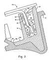
- FIGURE 3 is a cross-sectional view taken generally along the lines 3-3 of FIGURE 2 illustrating the weatherseal mounted to an associated vehicle flange.
- FIGURE 1 shows an embodiment of an elongated vehicle component such as a weatherstrip or weatherseal 20 having a first or upper end 22 and a second or lower end 24.
- the terms “upper” and “lower” refer to the installation positions of the respective ends of the weatherseal once installed on a vehicle such as an A-pillar of an automobile.
- the present invention is not limited to use along an A-pillar. Rather, one skilled in the art will appreciate that the features of this invention may be used in connection with other locations or components on the vehicle.
- the weatherseal 20 is a molded construction, particularly a dual shot molded construction.
- different portions of the weatherseal are formed from different moldable materials, and the structure is not removed from the mold until all materials have been introduced and at least partially cured, i.e., a first shot or introduction of first molding material, and a second shot or introduction of a second molding material, whereby the materials are maintained in the mold until sufficiently cured for removal.
- seams are limited between the different mold materials and a unitary, one-piece molded structure exhibiting different properties in different regions of the weatherseal is achieved.
- a first longitudinal wall 30 extends from one edge of a base wall 32 and a second wall 34 extends from a second edge of the base wall.
- the first and second walls 30, 34 extend in generally parallel relation and are substantially perpendicular to the base wall 32 to define a generally U-shaped structure. Moreover, these walls extend generally along the entire length of the weather seal. More specifically, the first wall 30 is continuous from the first end 22 to the second end 24.
- the second wall 34 has spaced portions or regions 36 so that the series of spaced portions 34 defines the second wall.
- the base wall 32 extends beyond the second wall 34 (as represented by reference numeral 32a ).
- the first and second walls, and the base wall are all preferably made from a first moldable material.
- the first molded material is a generally rigid thermoplastic.
- a seal lip 38 extends at an angle outwardly from an edge of the base wall portion 32a.
- the lip 38 is preferable formed of a second, less rigid molded material that will more easily deflect or conform in response to light pressure. This second molded material is ideal for allowing the lip to merge into engagement with the window along the A-pillar section.
- the seal lip has a slightly wider or thicker conformation where it joins to the bottom wall 32a and tapers or thins to an edge 38a that engages with the glass.
- edge 38a is slightly more pliable than edge 38b that joins with the more rigid plastic along the edge of base wall 32a.
- the tapered seal also extends substantially along the length of the weather seal from the first end to the second end.
- the base wall 32 thins as it extends longitudinally to its terminal end, and thus becomes slightly more flexible than the remainder of the base wall along the longitudinal extent of the weather seal. This allows the end 22 to conform more easily to the vehicle.
- the seal lip 38 tapers as shown at 38c and merges into this more flexible portion of the base wall 32, referenced as 32b.
- one of the wall portions 34 (namely the right-hand most wall portion, or uppermost wall portion, as shown in Figure 1 ) is interconnected at one end with the first wall portion 30.
- an additional wall 50 interconnects one end of second wall portion 34 with first wall portion 30.
- a molded detail is also provided at the opposite or lower end 24 of the weather seal.
- a generally triangular flange 52 extends generally perpendicularly from the rigid wall 30.
- the triangular portion is also formed from the second molded material and has greater flexibility than the first molded material.
- this detail allows the weatherseal to conform to the vehicle and fill a similarly sized gap between adjacent components of the vehicle.
- an enlarged formed detail or mucket 54 extends from a longitudinal end of the weatherseal.
- This component detail is also preferably primarily formed from the more flexible or second molded material, although portions thereof may also include the first molded material to provide some directional rigidity to the component for alignment and stability with the vehicle.
- the weatherseal is a molded element, whether it be molded in a single shot or more than one shot, great flexibility is achieved and allows the designer to incorporate other features into the weatherseal. These features are of the type that normally can only be achieved with a post-extrusion operation (and associated attendant cost) with a prior art extruded arrangement, whereas this molded assembly can more easily conform to an infinite variety of designs.
- a series of projections or fingers 60 are disposed in spaced groups and extend inwardly from the first wall 30 toward the second wall 34 .
- Each group in the exemplary embodiment includes four individual fingers.
- Each finger 60 includes an undercut portion 62 and an outwardly projecting portion 64 .
- the interface between the undercut and projection is defined by a shoulder 66.
- the undercut portions 62 are disposed more closely adjacent the base wall 32 .
- Tapered lead in regions 68 are provided on each finger and extend from the projecting portion and taper or merge outwardly toward the edge of the wall 30 remote from the base wall.
- groups of fingers are also disposed on an inner surface of second wall 34 .
- the second wall 34 is discontinuous at regions 36 along its length. These discontinuities or gaps conveniently align at locations opposite the groups of fingers 60 from the first wall.
- the second group of fingers 80 are disposed in groups of five and, except for the end-most groups, are joined together in paired groups by the second wall 34 . Each of the group of second fingers 80 are thus offset axially or longitudinally along the weather seal from the first group of fingers 60.
- each finger 80 includes a projecting portion 82 , an undercut portion 84, and a shoulder 86 transitioning between the two.
- the undercut portion on the fingers 60 are disposed closer to the base wall along the first wall, it is the projecting portion 82 of the second group of fingers 80 that is disposed closer to the base wall 32 along the second wall 34 .
- the undercut portions 84 merge into a terminal edge of the wall 34 via tapered lead-in portions 88 ,
- vehicle flange 90 has a generally S-shape, having a first portion 92 that extends generally parallel to a second portion 94 and interconnected by an angled or transition portion 96 .
- the offset and size of the flange is such that the flange fits between the first and second walls 30, 34.
- the conformations of the fingers 60, 80 also have a mating arrangement with that of the offset portions 92 , 94 of the flange, as well as the interconnecting portion 96.
- projecting portion 82 of the second fingers and undercut portion 62 of the first finger run generally parallel to the first portion 92 of the vehicle flange.
- undercut portion 84 of the second finger and projecting portion 64 of the first finger run parallel to the second portion 94 of the flange, while transition portion 96 is generally disposed between the shoulders 66 , 86 of the first and second fingers, respectively.
- the walls 30 , 34 are generally rigid with the fingers directed inwardly toward the opposite facing wall, it will be appreciated that when the walls 30, 34 are advanced in a direction generally parallel to the extent of the walls (see reference numeral 100 ) and over the flange 90 , that the fingers and associated walls will flex slightly outward and then snap-fit inwardly toward their non-deflected position as shown in FIGURE 3 once the flange is fully received between the opposing fingers. It will also be appreciated that none of the fingers are disposed directly opposite a set of fingers from the other wall along the longitudinal extent of the weatherseal. This, too, facilitates insertion.
- shoulder 50 is engaged over an upper edge of the flange 90.
- the remainder of the weatherseal is then advanced over the flange 90 by pressing the weather seal in a direction generally shown by the reference arrow 100 in FIGURE 3 .
- Leading ends 68 , 88 of the fingers taper outwardly to advance over flange portion 92.
- the flange is advanced through the offset path defined between the fingers until fully seated as shown in FIGURE 3 .
- an audible click or snap is heard, and the tactile sensation of the weatherseal seating in place as shown in FIGURE 3 is felt a flange portion 92 advance to the fully inserted position as shown in FIGURE 3 , where shoulders 66 , 86 seat against the transition region 96 of the flange.
- the preferred embodiment uses preselected groups of fingers ("seven groups of fingers 60 ", "second group of fingers 80 are disposed in groups of five", etc.).
- This invention should not be limited to a specific number of fingers or a specific number of groups as will be appreciated by one skilled in the art.
- the invention allows components or products to effectively attach to "S" shaped flanges (whether it be used for sealing, trim, or other areas where a part needs to be snapped on to an attachment flange) and have many operations at the manufacturing level reduced, as well as eliminating the need for a metal core and thereby reducing weight and cost.
- the array of locking features can be altered to suit insertion or extraction requirements for the product.
- the invention is intended to include all such modifications and alterations insofar as they come within the scope of the appended claims.
Landscapes
- Engineering & Computer Science (AREA)
- Mechanical Engineering (AREA)
- Seal Device For Vehicle (AREA)
- Injection Moulding Of Plastics Or The Like (AREA)
- Sealing Material Composition (AREA)
Description
- Weatherseals or weatherstrips provided around a perimeter of a door opening are common in the industry. For example, one or more weatherstrips are provided about the inner perimeter of the door opening, for example along the A-pillar, header portion, B-pillar, etc. One such known structure is an extruded seal that includes a metal core. The metal core has a generally U-shaped profile and is embedded within an extruded elastomeric material. Generally parallel legs of the U-shaped profile include gripping portions that extend along the entire longitudinal extent of the profile into the cavity between the legs and provide for the gripping engagement because the gripping portions are extruded. A state of the art weatherseal is disclosed in
GB 2273952A - One leg of the weatherseal profile is disposed adjacent an external surface of the weatherseal when the weatherseal is positioned on the vehicle. As the elastomeric material cures over the surface of the metal core, unfortunately the external surface of the elastomer often assumes or shows the configuration of the core metal. This can result in an unsightly or non-pleasing appearance to the weatherseal, sometimes referred to as "hungry-horse" since the lanced metal core shows through the elastomeric extrudate like a series of ribs protruding from a horse. Using a core such as the lanced metal core is desirable since the core provides additional strength for manipulating and mounting the weatherseal to the vehicle. On the other hand, the core oftentimes limits the design since the core is typically an extruded profile. Formation by extruding limits the design to cross-sectional configurations that can be extruded, i.e., symmetrical along a longitudinal axis, and if additional non-symmetrical features, designs, or profiles are desired, or features that extend generally perpendicular to the axis of extrusion, post-extrusion steps are required to modify the extruded cross-section. For example, it may be desirable to close out one end of the extruded weatherseal in order to merge the weatherseal with the vehicle body and limit any unsightly gaps. Likewise, it is commonplace to provide post-extrusion secondary operations to the weatherseal that cannot be achieved during the extrusion process, including molded details.
- It is common that the core is metal while the extrudate is an elastomer such as rubber or thermoplastic. The metal core adds weight to the overall structure. In addition, the different materials of construction incorporated into the weatherseal are not desirable from a recycling standpoint since the materials must be segregated. Thus, either the costs to recycle the material become too expensive or, as is more often the case, the component is simply not recycled due to such expense.
- In addition, mounting the extruded weatherseal to the vehicle flange has its attendant problems. Specifically a tool, such as a mallet, is typically used by the installer on the vehicle assembly line to forcibly secure the weatherseal on the vehicle flange, but without any precision. That is, the operator must rely on his or her own expertise to determine whether the weather seal is properly installed. The U-shaped profile of the gripping legs of the weather seal are advanced over the S-flange of the vehicle body. Other than visual perception, there is no assurance or feed-back to the installer that the weather seal has been properly secured to the flange. Unfortunately, from a quality control standpoint, this is not desirable since there is no assurance that installation from one vehicle to the next is the same.
- Thus, a need exists for a lighter weight weatherseal that is more conducive to recycling, less expensive to manufacture, has greater capability of design variation, and provides a confirmation to the installer of proper installation.
- An improved automotive component such as a weatherseal incorporates a snap-fit connecting feature that provides both an audible and tactile "click" or "snap" when the weatherseal is properly installed on a vehicle flange.
- The weatherseal is preferably a molded construction allowing variation in the cross-sectional profile along its length.
- The weather seal advantageously includes protrusions or fingers that are axially spaced along the length of the weather seal. The fingers preferably have a shoulder separating an undercut region from an enlarged holding portion. The advancement of the holding portion over the vehicle flange so that the flange is engaged by the holding portion and the undercut region provides an audible and tactile response, i.e., a click or snap, that can be easily perceived by the installer.
- According to a preferred arrangement, selected groups of fingers are joined by an interconnecting wall to provide flexibility in installation and flexibility to the weatherseal to conform to the vehicle flange.
- The fingers preferably have tapered or chamfered lead-in portions to facilitate advancement of the weatherseal over the flange during installation.
- A primary advantage resides in the assurance of a proper installation of the weatherseal on the vehicle.
- Another advantage is associated with the low cost.
- Still another feature is the ability to provide a wide array of design profiles.
- Still another advantage is the ease with which the components can be recycled.
- Yet another feature is the light weight of the component that contributes to overall weight reduction of the vehicle.
- Still other features and advantages will become apparent from reading and understanding the following detailed description.
-
FIGURE 1 is a perspective view of the subject new weatherseal. -
FIGURE 2 is an enlarged view of the groups of gripping fingers employed in the weatherseal ofFIGURE 1 . -
FIGURE 3 is a cross-sectional view taken generally along the lines 3-3 ofFIGURE 2 illustrating the weatherseal mounted to an associated vehicle flange. -
FIGURE 1 shows an embodiment of an elongated vehicle component such as a weatherstrip or weatherseal 20 having a first orupper end 22 and a second orlower end 24. The terms "upper" and "lower" refer to the installation positions of the respective ends of the weatherseal once installed on a vehicle such as an A-pillar of an automobile. However, the present invention is not limited to use along an A-pillar. Rather, one skilled in the art will appreciate that the features of this invention may be used in connection with other locations or components on the vehicle. The weatherseal 20 is a molded construction, particularly a dual shot molded construction. In other words, different portions of the weatherseal are formed from different moldable materials, and the structure is not removed from the mold until all materials have been introduced and at least partially cured, i.e., a first shot or introduction of first molding material, and a second shot or introduction of a second molding material, whereby the materials are maintained in the mold until sufficiently cured for removal. In this manner, seams are limited between the different mold materials and a unitary, one-piece molded structure exhibiting different properties in different regions of the weatherseal is achieved. - As shown in
FIGURES 1 and2 , a firstlongitudinal wall 30 extends from one edge of abase wall 32 and asecond wall 34 extends from a second edge of the base wall. Preferably, the first andsecond walls base wall 32 to define a generally U-shaped structure. Moreover, these walls extend generally along the entire length of the weather seal. More specifically, thefirst wall 30 is continuous from thefirst end 22 to thesecond end 24. Thesecond wall 34, on the other hand, has spaced portions orregions 36 so that the series of spacedportions 34 defines the second wall. Thebase wall 32 extends beyond the second wall 34 (as represented byreference numeral 32a). - The first and second walls, and the base wall are all preferably made from a first moldable material. For the particular purposes here, the first molded material is a generally rigid thermoplastic. On the other hand, a
seal lip 38 extends at an angle outwardly from an edge of thebase wall portion 32a. Thelip 38 is preferable formed of a second, less rigid molded material that will more easily deflect or conform in response to light pressure. This second molded material is ideal for allowing the lip to merge into engagement with the window along the A-pillar section. Preferably the seal lip has a slightly wider or thicker conformation where it joins to thebottom wall 32a and tapers or thins to anedge 38a that engages with the glass. Thus, due to its reduced cross-sectional thickness, theedge 38a is slightly more pliable thanedge 38b that joins with the more rigid plastic along the edge ofbase wall 32a. As will also be appreciated, and as illustrated inFIGURE 1 , the tapered seal also extends substantially along the length of the weather seal from the first end to the second end. - With continued reference to
FIGURE 1 , close out details or profiles are provided at the opposite ends. For example, at thefirst end 22, thebase wall 32 thins as it extends longitudinally to its terminal end, and thus becomes slightly more flexible than the remainder of the base wall along the longitudinal extent of the weather seal. This allows theend 22 to conform more easily to the vehicle. In addition, theseal lip 38 tapers as shown at 38c and merges into this more flexible portion of thebase wall 32, referenced as 32b. - In addition, one of the wall portions 34 (namely the right-hand most wall portion, or uppermost wall portion, as shown in
Figure 1 ) is interconnected at one end with thefirst wall portion 30. Stated another way, anadditional wall 50 interconnects one end ofsecond wall portion 34 withfirst wall portion 30. This is a typical close-out used in the prior art to accurately locate the longitudinal position of the weatherseal on the vehicle. That is, the inner surface of thewall 50 forms an abutment surface that engages a vehicle flange (as will be described in greater detail with respect toFIGURE 3 ) and accurately locates the longitudinal position of the weatherseal relative to the vehicle. - A molded detail is also provided at the opposite or
lower end 24 of the weather seal. Specifically, a generallytriangular flange 52 extends generally perpendicularly from therigid wall 30. Preferably the triangular portion is also formed from the second molded material and has greater flexibility than the first molded material. Again, this detail allows the weatherseal to conform to the vehicle and fill a similarly sized gap between adjacent components of the vehicle. Further, an enlarged formed detail ormucket 54 extends from a longitudinal end of the weatherseal. This component detail is also preferably primarily formed from the more flexible or second molded material, although portions thereof may also include the first molded material to provide some directional rigidity to the component for alignment and stability with the vehicle. - It will be recognized that since the weatherseal is a molded element, whether it be molded in a single shot or more than one shot, great flexibility is achieved and allows the designer to incorporate other features into the weatherseal. These features are of the type that normally can only be achieved with a post-extrusion operation (and associated attendant cost) with a prior art extruded arrangement, whereas this molded assembly can more easily conform to an infinite variety of designs.
- With continued reference to
FIGURES 1 and2 , and more specific attention toFIGURE 3 , the audible and tactile snap feature will be shown and described in greater detail. Particularly, a series of projections orfingers 60 are disposed in spaced groups and extend inwardly from thefirst wall 30 toward thesecond wall 34. By way of example only, there are seven groups offingers 60 generally equi-spaced along the longitudinal extent of thefirst wall 30. Each group in the exemplary embodiment includes four individual fingers. Eachfinger 60 includes an undercutportion 62 and an outwardly projectingportion 64. The interface between the undercut and projection is defined by ashoulder 66. As will be appreciated, theundercut portions 62 are disposed more closely adjacent thebase wall 32. Tapered lead inregions 68 are provided on each finger and extend from the projecting portion and taper or merge outwardly toward the edge of thewall 30 remote from the base wall. - In a similar fashion, groups of fingers are also disposed on an inner surface of
second wall 34. As previously noted, thesecond wall 34 is discontinuous atregions 36 along its length. These discontinuities or gaps conveniently align at locations opposite the groups offingers 60 from the first wall. The second group offingers 80 are disposed in groups of five and, except for the end-most groups, are joined together in paired groups by thesecond wall 34. Each of the group ofsecond fingers 80 are thus offset axially or longitudinally along the weather seal from the first group offingers 60. - In addition, each
finger 80 includes a projectingportion 82, an undercutportion 84, and ashoulder 86 transitioning between the two. Whereas the undercut portion on thefingers 60 are disposed closer to the base wall along the first wall, it is the projectingportion 82 of the second group offingers 80 that is disposed closer to thebase wall 32 along thesecond wall 34. Stated another way, theundercut portions 84 merge into a terminal edge of thewall 34 via tapered lead-inportions 88, - As shown in
FIGURE 3 , the weatherseal is shown mounted on a vehicle flange. As will be appreciated,vehicle flange 90 has a generally S-shape, having afirst portion 92 that extends generally parallel to asecond portion 94 and interconnected by an angled ortransition portion 96. The offset and size of the flange is such that the flange fits between the first andsecond walls FIGURE 3 , the conformations of thefingers portions portion 96. That is, projectingportion 82 of the second fingers and undercutportion 62 of the first finger run generally parallel to thefirst portion 92 of the vehicle flange. Similarly, undercutportion 84 of the second finger and projectingportion 64 of the first finger run parallel to thesecond portion 94 of the flange, whiletransition portion 96 is generally disposed between theshoulders - Although the
walls walls flange 90, that the fingers and associated walls will flex slightly outward and then snap-fit inwardly toward their non-deflected position as shown inFIGURE 3 once the flange is fully received between the opposing fingers. It will also be appreciated that none of the fingers are disposed directly opposite a set of fingers from the other wall along the longitudinal extent of the weatherseal. This, too, facilitates insertion. - As noted above,
shoulder 50 is engaged over an upper edge of theflange 90. The remainder of the weatherseal is then advanced over theflange 90 by pressing the weather seal in a direction generally shown by thereference arrow 100 inFIGURE 3 . Leading ends 68, 88 of the fingers taper outwardly to advance overflange portion 92. The flange is advanced through the offset path defined between the fingers until fully seated as shown inFIGURE 3 . When fully seated, an audible click or snap is heard, and the tactile sensation of the weatherseal seating in place as shown inFIGURE 3 is felt aflange portion 92 advance to the fully inserted position as shown inFIGURE 3 , whereshoulders transition region 96 of the flange. - The invention has been described with reference to the preferred embodiment. Obviously, modifications and alterations will occur to others upon a reading and understanding of this specification. For example, the preferred embodiment uses preselected groups of fingers ("seven groups of
fingers 60", "second group offingers 80 are disposed in groups of five", etc.). This invention should not be limited to a specific number of fingers or a specific number of groups as will be appreciated by one skilled in the art. However, the invention allows components or products to effectively attach to "S" shaped flanges (whether it be used for sealing, trim, or other areas where a part needs to be snapped on to an attachment flange) and have many operations at the manufacturing level reduced, as well as eliminating the need for a metal core and thereby reducing weight and cost. Likewise, the array of locking features can be altered to suit insertion or extraction requirements for the product. The invention is intended to include all such modifications and alterations insofar as they come within the scope of the appended claims.
Claims (20)
- A weatherseal (20) adapted for receipt of an associated vehicle flange (90), the weatherseal (20) comprising:an elongated molded body having first (30) and second (34) substantially rigid walls disposed in generally parallel arrangement along a longitudinal axis, and interconnected to one another by a base wall (32);first projections (60) extending from the first wall (30) toward the second wall (34); andsecond projections (80) extending from the second wall (34) toward the first wall (30), the second projections (80) axially offset from the first projections (60) along the longitudinal axis, the first and second projections (60, 80) being dimensioned to engage opposite faces of the associated vehicle flange (90) when the weatherseal (20) is received thereon.
- The weatherseal (20) of claim 1 wherein the first projections (60) are disposed in segregated groups along the first wall (30).
- The weatherseal (20) of claim 2 wherein the second projections (80) are disposed in segregated groups along the second wall (34).
- The weatherseal (20) of claim 2 wherein the first projections (60) include undercut portions (62) separated by a shoulder (66) from protruding portions (64) thereof for engaging offset surfaces of the associated flange (90).
- The weatherseal (20) of claim 1 wherein the first projections (60) include undercut portions (62) separated by a shoulder (66) from protruding portions (64) thereof for engaging offset surfaces of the associated flange (90).
- The weatherseal (20) of claim 5 wherein the second projections (80) include undercut portions (84) separated by a shoulder (86) from protruding portions (82) thereof for engaging offset surfaces of the associated flange (90).
- The weatherseal (20) of claim 6 wherein the undercut portions (62) of the first projections (60) are disposed closer to the base wall (32) than the protruding portions (64) thereof, while the undercut portions (84) of the second projections (80) are further from the base wall (32) than the protruding portions (82) thereof.
- The weatherseal (20) of claim 1 wherein the second wall (34) includes intermittent spaces (36) along its length.
- The weatherseal (20) of claim 8 wherein the first projections (60) are spaced along the first wall (30) and disposed opposite the spaces (36) in the second wall (34).
- The weatherseal (20) of claim 1 further comprising a seal lip (38) extending from the weatherseal (20).
- The weatherseal (20) of claim 10 wherein the seal lip (38) is formed from a more flexible material than the body.
- The weatherseal (20) of claim 1 wherein the first (30) and second (34) walls are joined by an interconnecting wall adjacent one end of the weatherseal (20).
- The weatherseal (20) of claim 1 wherein the first (60) and second (80) projections are disposed in longitudinally spaced groups.
- The weatherseal (20) of claim 13 wherein selected ones of adjacent groups of the second projections (80) are joined by a second wall portion.
- The weatherseal (20) of claim 13 wherein selected ones of adjacent groups of the second projections (80) are longitudinally spaced.
- The weatherseal (20) of claim 1 further comprising a detail adjacent a second end (24) of the weatherseal formed at least in part of a molded material that is less rigid than the body of the weatherseal (20).
- A method of manufacturing a weatherseal (20) having a generally U-shaped attachment portion for mounting on an associated vehicle, the method comprising:forming a first set of retaining fingers (60) on a first wall (30) of the attachment portion from a first material; andforming, from the first material, a second set of retaining fingers (80) on a second wall (34) facing the first wall (30) of the attachment portion, the second finger set being offset from the first set of retaining fingers.
- The method of claim 17 wherein the forming steps are molding the fingers (60, 80).
- The method of claim 17 further comprising molding a seal lip (38) to the weatherseal (20) in the same mold from a second material that is more flexible than the first material.
- The method of claim 19 further comprising molding an interconnecting wall (32) that joins the first (30) and second (34) walls at one end of the weatherseal (20).
Applications Claiming Priority (2)
| Application Number | Priority Date | Filing Date | Title |
|---|---|---|---|
| US11/485,501 US7726075B2 (en) | 2006-07-12 | 2006-07-12 | Dual-shot injection molded weatherseal |
| PCT/US2007/015627 WO2008008290A2 (en) | 2006-07-12 | 2007-07-06 | Dual-shot injection molded weatherseal |
Publications (3)
| Publication Number | Publication Date |
|---|---|
| EP2041384A2 EP2041384A2 (en) | 2009-04-01 |
| EP2041384A4 EP2041384A4 (en) | 2012-08-29 |
| EP2041384B1 true EP2041384B1 (en) | 2013-10-23 |
Family
ID=38923810
Family Applications (1)
| Application Number | Title | Priority Date | Filing Date |
|---|---|---|---|
| EP07810265.4A Ceased EP2041384B1 (en) | 2006-07-12 | 2007-07-06 | Dual-shot injection molded weatherseal |
Country Status (6)
| Country | Link |
|---|---|
| US (1) | US7726075B2 (en) |
| EP (1) | EP2041384B1 (en) |
| KR (1) | KR101473674B1 (en) |
| CA (1) | CA2660316C (en) |
| MX (1) | MX2009000485A (en) |
| WO (1) | WO2008008290A2 (en) |
Families Citing this family (4)
| Publication number | Priority date | Publication date | Assignee | Title |
|---|---|---|---|---|
| DE202008014739U1 (en) | 2008-11-06 | 2009-01-29 | Meteor Gummiwerke K.H. Bädje GmbH & Co. KG | Sealing arrangement for the window slot of a vehicle door |
| KR101250010B1 (en) * | 2010-11-15 | 2013-04-02 | 정준환 | Weather strip in car |
| US8701352B2 (en) | 2011-09-15 | 2014-04-22 | Ford Global Technologies, Llc | Two-shot secondary seal with clip |
| JP7095263B2 (en) * | 2017-11-10 | 2022-07-05 | 株式会社アイシン | Wind glass support structure for vehicle doors |
Family Cites Families (13)
| Publication number | Priority date | Publication date | Assignee | Title |
|---|---|---|---|---|
| GB2037354A (en) * | 1978-10-26 | 1980-07-09 | United Carr Ltd | Windscreen Moulding Clip |
| ES2053127T3 (en) * | 1989-12-28 | 1994-07-16 | Kinugawa Rubber Ind | WEATHER-RESISTANT BAND STRUCTURE FOR AUTOMOBILE VEHICLES. |
| GB9226324D0 (en) * | 1992-12-17 | 1993-02-10 | Draftex Ind Ltd | Sealing,trimming and finishing strips |
| DE4314191C1 (en) * | 1993-04-30 | 1994-08-04 | Baedje K H Meteor Gummiwerke | Method and device for the co-vulcanization of thermoplastics and elastomers |
| FR2729397B1 (en) * | 1995-01-12 | 1997-03-28 | Hutchinson | COMPOSITE ELASTOMER AND THERMOPLASTIC PRODUCT AND METHODS OF MAKING SAME |
| GB2300732B (en) * | 1995-05-12 | 1998-12-09 | Standard Prod Ltd | Window sealing system with piezo-electric cable anti-trap sensor |
| US6305125B1 (en) * | 1995-10-09 | 2001-10-23 | Toyoda Gosei Co., Ltd. | Window guide having a plurality of contact members attached at only one end for guiding an automobile door window |
| JP3294494B2 (en) * | 1996-03-05 | 2002-06-24 | オーエム工業株式会社 | Resin lower sash |
| US5943823A (en) * | 1997-02-06 | 1999-08-31 | Om Corporation | Lower sash made of synthetic resin for automotive vehicle door |
| US6247271B1 (en) * | 1997-09-24 | 2001-06-19 | Ford Global Technologies, Inc. | Automotive door seal for accommodating weld flanges having different thicknesses |
| JP3883787B2 (en) * | 2000-06-26 | 2007-02-21 | 豊田合成株式会社 | Glass guide |
| GB2370307A (en) * | 2000-12-21 | 2002-06-26 | Draftex Ind Ltd | Sealing or trim strip with pivoting limbs to grip a flange |
| GB2395973B (en) * | 2002-12-03 | 2005-12-07 | Gencorp Property Inc | Sealing,guiding and trimming strip arrangements and methods of making them |
-
2006
- 2006-07-12 US US11/485,501 patent/US7726075B2/en active Active
-
2007
- 2007-07-06 WO PCT/US2007/015627 patent/WO2008008290A2/en not_active Ceased
- 2007-07-06 KR KR1020097002651A patent/KR101473674B1/en not_active Expired - Fee Related
- 2007-07-06 CA CA2660316A patent/CA2660316C/en not_active Expired - Fee Related
- 2007-07-06 MX MX2009000485A patent/MX2009000485A/en active IP Right Grant
- 2007-07-06 EP EP07810265.4A patent/EP2041384B1/en not_active Ceased
Also Published As
| Publication number | Publication date |
|---|---|
| EP2041384A2 (en) | 2009-04-01 |
| MX2009000485A (en) | 2009-03-23 |
| US7726075B2 (en) | 2010-06-01 |
| US20080010903A1 (en) | 2008-01-17 |
| WO2008008290A3 (en) | 2008-10-30 |
| KR20090037934A (en) | 2009-04-16 |
| EP2041384A4 (en) | 2012-08-29 |
| CA2660316C (en) | 2014-05-13 |
| WO2008008290A2 (en) | 2008-01-17 |
| CA2660316A1 (en) | 2008-01-17 |
| KR101473674B1 (en) | 2014-12-17 |
Similar Documents
| Publication | Publication Date | Title |
|---|---|---|
| EP1838545B1 (en) | Encapsulated fixed window module | |
| EP1849638B1 (en) | Glass run | |
| EP1388449B1 (en) | Weather strip for a vehicle door | |
| EP2602139B1 (en) | Glass run channel assembly | |
| US20140000174A1 (en) | Door weather strip | |
| US20110078959A1 (en) | Opening trim weather strip | |
| US20190118732A1 (en) | Vehicle door glass run and method for assembling the same | |
| US11117454B2 (en) | Seal component for vehicle door window | |
| CA2660316C (en) | Dual-shot injection molded weatherseal | |
| JP5025651B2 (en) | Weather strip incorporating anti-pinch sensor, weather strip assembly, and method of forming weather strip | |
| US12365225B2 (en) | Outer belt with molded snap-fit retention feature | |
| CN113879080B (en) | Glass run channel for car doors | |
| US7513079B2 (en) | Glass run and method for manufacturing the same | |
| CN214524077U (en) | Separation column for automobile | |
| EP2159108B1 (en) | Sealing Assembly and Method for Producing that Sealing Assembly | |
| US20020001696A1 (en) | Glass run and method for manufacturing the same | |
| US20190241055A1 (en) | Single shot extrusion of glass run channel | |
| JP3714134B2 (en) | Glass run assembly structure | |
| EP1343650A1 (en) | Sealing, trimming and finishing strips | |
| JP7862116B2 (en) | Belt molding | |
| JP2008105530A (en) | Door weather strip and its manufacturing method | |
| JPH05301525A (en) | Weather strip for hatch roof | |
| JPH1071618A (en) | Weather strip mold connection method | |
| JP2003175728A (en) | Automotive glass run | |
| JP2002274282A (en) | Moulding for automobile |
Legal Events
| Date | Code | Title | Description |
|---|---|---|---|
| PUAI | Public reference made under article 153(3) epc to a published international application that has entered the european phase |
Free format text: ORIGINAL CODE: 0009012 |
|
| 17P | Request for examination filed |
Effective date: 20090130 |
|
| AK | Designated contracting states |
Kind code of ref document: A2 Designated state(s): AT BE BG CH CY CZ DE DK EE ES FI FR GB GR HU IE IS IT LI LT LU LV MC MT NL PL PT RO SE SI SK TR |
|
| AX | Request for extension of the european patent |
Extension state: AL BA HR MK RS |
|
| DAX | Request for extension of the european patent (deleted) | ||
| RBV | Designated contracting states (corrected) |
Designated state(s): DE FR GB |
|
| REG | Reference to a national code |
Ref country code: DE Ref legal event code: R079 Ref document number: 602007033494 Country of ref document: DE Free format text: PREVIOUS MAIN CLASS: E05D0013000000 Ipc: B60J0010000000 |
|
| A4 | Supplementary search report drawn up and despatched |
Effective date: 20120726 |
|
| RIC1 | Information provided on ipc code assigned before grant |
Ipc: B60J 10/00 20060101AFI20120720BHEP |
|
| GRAP | Despatch of communication of intention to grant a patent |
Free format text: ORIGINAL CODE: EPIDOSNIGR1 |
|
| GRAP | Despatch of communication of intention to grant a patent |
Free format text: ORIGINAL CODE: EPIDOSNIGR1 |
|
| INTG | Intention to grant announced |
Effective date: 20130805 |
|
| GRAS | Grant fee paid |
Free format text: ORIGINAL CODE: EPIDOSNIGR3 |
|
| GRAA | (expected) grant |
Free format text: ORIGINAL CODE: 0009210 |
|
| AK | Designated contracting states |
Kind code of ref document: B1 Designated state(s): DE FR GB |
|
| REG | Reference to a national code |
Ref country code: GB Ref legal event code: FG4D |
|
| REG | Reference to a national code |
Ref country code: DE Ref legal event code: R096 Ref document number: 602007033494 Country of ref document: DE Effective date: 20131219 |
|
| REG | Reference to a national code |
Ref country code: DE Ref legal event code: R097 Ref document number: 602007033494 Country of ref document: DE |
|
| PLBE | No opposition filed within time limit |
Free format text: ORIGINAL CODE: 0009261 |
|
| STAA | Information on the status of an ep patent application or granted ep patent |
Free format text: STATUS: NO OPPOSITION FILED WITHIN TIME LIMIT |
|
| 26N | No opposition filed |
Effective date: 20140724 |
|
| REG | Reference to a national code |
Ref country code: DE Ref legal event code: R097 Ref document number: 602007033494 Country of ref document: DE Effective date: 20140724 |
|
| REG | Reference to a national code |
Ref country code: FR Ref legal event code: PLFP Year of fee payment: 9 |
|
| REG | Reference to a national code |
Ref country code: FR Ref legal event code: PLFP Year of fee payment: 10 |
|
| REG | Reference to a national code |
Ref country code: FR Ref legal event code: PLFP Year of fee payment: 11 |
|
| REG | Reference to a national code |
Ref country code: FR Ref legal event code: PLFP Year of fee payment: 12 |
|
| PGFP | Annual fee paid to national office [announced via postgrant information from national office to epo] |
Ref country code: FR Payment date: 20210629 Year of fee payment: 15 |
|
| PGFP | Annual fee paid to national office [announced via postgrant information from national office to epo] |
Ref country code: GB Payment date: 20210629 Year of fee payment: 15 |
|
| PGFP | Annual fee paid to national office [announced via postgrant information from national office to epo] |
Ref country code: DE Payment date: 20210616 Year of fee payment: 15 |
|
| REG | Reference to a national code |
Ref country code: DE Ref legal event code: R119 Ref document number: 602007033494 Country of ref document: DE |
|
| GBPC | Gb: european patent ceased through non-payment of renewal fee |
Effective date: 20220706 |
|
| PG25 | Lapsed in a contracting state [announced via postgrant information from national office to epo] |
Ref country code: FR Free format text: LAPSE BECAUSE OF NON-PAYMENT OF DUE FEES Effective date: 20220731 |
|
| PG25 | Lapsed in a contracting state [announced via postgrant information from national office to epo] |
Ref country code: GB Free format text: LAPSE BECAUSE OF NON-PAYMENT OF DUE FEES Effective date: 20220706 Ref country code: DE Free format text: LAPSE BECAUSE OF NON-PAYMENT OF DUE FEES Effective date: 20230201 |