EP2040979B1 - Verfahren, vorrichtung und anlage zur herstellung von muschelstrukturen - Google Patents
Verfahren, vorrichtung und anlage zur herstellung von muschelstrukturen Download PDFInfo
- Publication number
- EP2040979B1 EP2040979B1 EP07825918A EP07825918A EP2040979B1 EP 2040979 B1 EP2040979 B1 EP 2040979B1 EP 07825918 A EP07825918 A EP 07825918A EP 07825918 A EP07825918 A EP 07825918A EP 2040979 B1 EP2040979 B1 EP 2040979B1
- Authority
- EP
- European Patent Office
- Prior art keywords
- shell
- raw shell
- raw
- plant
- carriage
- Prior art date
- Legal status (The legal status is an assumption and is not a legal conclusion. Google has not performed a legal analysis and makes no representation as to the accuracy of the status listed.)
- Not-in-force
Links
Images



Classifications
-
- B—PERFORMING OPERATIONS; TRANSPORTING
- B64—AIRCRAFT; AVIATION; COSMONAUTICS
- B64F—GROUND OR AIRCRAFT-CARRIER-DECK INSTALLATIONS SPECIALLY ADAPTED FOR USE IN CONNECTION WITH AIRCRAFT; DESIGNING, MANUFACTURING, ASSEMBLING, CLEANING, MAINTAINING OR REPAIRING AIRCRAFT, NOT OTHERWISE PROVIDED FOR; HANDLING, TRANSPORTING, TESTING OR INSPECTING AIRCRAFT COMPONENTS, NOT OTHERWISE PROVIDED FOR
- B64F5/00—Designing, manufacturing, assembling, cleaning, maintaining or repairing aircraft, not otherwise provided for; Handling, transporting, testing or inspecting aircraft components, not otherwise provided for
- B64F5/50—Handling or transporting aircraft components
-
- Y—GENERAL TAGGING OF NEW TECHNOLOGICAL DEVELOPMENTS; GENERAL TAGGING OF CROSS-SECTIONAL TECHNOLOGIES SPANNING OVER SEVERAL SECTIONS OF THE IPC; TECHNICAL SUBJECTS COVERED BY FORMER USPC CROSS-REFERENCE ART COLLECTIONS [XRACs] AND DIGESTS
- Y10—TECHNICAL SUBJECTS COVERED BY FORMER USPC
- Y10T—TECHNICAL SUBJECTS COVERED BY FORMER US CLASSIFICATION
- Y10T29/00—Metal working
- Y10T29/49—Method of mechanical manufacture
- Y10T29/49616—Structural member making
- Y10T29/49622—Vehicular structural member making
-
- Y—GENERAL TAGGING OF NEW TECHNOLOGICAL DEVELOPMENTS; GENERAL TAGGING OF CROSS-SECTIONAL TECHNOLOGIES SPANNING OVER SEVERAL SECTIONS OF THE IPC; TECHNICAL SUBJECTS COVERED BY FORMER USPC CROSS-REFERENCE ART COLLECTIONS [XRACs] AND DIGESTS
- Y10—TECHNICAL SUBJECTS COVERED BY FORMER USPC
- Y10T—TECHNICAL SUBJECTS COVERED BY FORMER US CLASSIFICATION
- Y10T29/00—Metal working
- Y10T29/53—Means to assemble or disassemble
- Y10T29/53539—Means to assemble or disassemble including work conveyor
-
- Y—GENERAL TAGGING OF NEW TECHNOLOGICAL DEVELOPMENTS; GENERAL TAGGING OF CROSS-SECTIONAL TECHNOLOGIES SPANNING OVER SEVERAL SECTIONS OF THE IPC; TECHNICAL SUBJECTS COVERED BY FORMER USPC CROSS-REFERENCE ART COLLECTIONS [XRACs] AND DIGESTS
- Y10—TECHNICAL SUBJECTS COVERED BY FORMER USPC
- Y10T—TECHNICAL SUBJECTS COVERED BY FORMER US CLASSIFICATION
- Y10T29/00—Metal working
- Y10T29/53—Means to assemble or disassemble
- Y10T29/53961—Means to assemble or disassemble with work-holder for assembly
- Y10T29/53974—Means to assemble or disassemble with work-holder for assembly having means to permit support movement while work is thereon
-
- Y—GENERAL TAGGING OF NEW TECHNOLOGICAL DEVELOPMENTS; GENERAL TAGGING OF CROSS-SECTIONAL TECHNOLOGIES SPANNING OVER SEVERAL SECTIONS OF THE IPC; TECHNICAL SUBJECTS COVERED BY FORMER USPC CROSS-REFERENCE ART COLLECTIONS [XRACs] AND DIGESTS
- Y10—TECHNICAL SUBJECTS COVERED BY FORMER USPC
- Y10T—TECHNICAL SUBJECTS COVERED BY FORMER US CLASSIFICATION
- Y10T29/00—Metal working
- Y10T29/53—Means to assemble or disassemble
- Y10T29/53991—Work gripper, anvil, or element
Definitions
- the present invention relates to a method, a gripping device, an equipment and a plant for working shell structures, in particular but not limited to shell structures of aircrafts.
- a technique currently under way of development consists in assembling the airplane fuselage by connecting a plurality of cylindrical and non-cylindrical segments, currently named “barrel” in the Anglo-Saxon technical jargon, or correspondingly “barili” in the Italian jargon.
- the barrels that will form an aircraft can be manufactured by different constructors, and delivered already provided with floors, seats, windows and doors before the complete fuselage is assembled.
- WO 2006/001860 A discloses an example of composite sections for aircraft fuselages and methods and systems for manufacturing such sections.
- a composite section configured in accordance with one embodiment of the above cited document includes a skin and at least first and second stiffeners.
- the skin can include a plurality of unidirectional fibers forming a continuous surface extending 360 degrees about an axis.
- the first stiffener can include a first flange portion bonded to an interior surface of the skin and a first raised portion projecting inwardly and away from the interior surface of the skin.
- the second stiffener can include a second flange portion bonded to the interior surface of the skin and a second raised portion projecting inwardly and away from the interior surface of the skin.
- EP 1 149 687 A discloses a method for producing a body structure composed of a stiffened panel of a fiber-reinforced composite, wherein (a) a skin member is placed on a forming tool, (b) a plurality of preformed stringer members are arranged on the skin member at predetermined intervals, (c) a plurality of preformed outer frame members are arranged on the skin member to intersect the preformed stringer members, (d) the skin member, the preformed stringer members and the preformed outer frame members are integrally hardened by heating under a pressure to prepare an assembly having a skin, stringers and an outer frame, (e) an inner frame member hardened by heating under a pressure beforehand is put into contact with the outer frame, and (f) the inner frame member and the assembly are adhesive-formed by heating under a pressure.
- a body structure produced by the method is also provided.
- US 1 922 063 A discloses examples of aircraft bodies and method of constructing the same, by providing a plurality of sheet metal cover sections; preforming and shaping the several cover sections so that said cover sections when placed edge to edge will conform, in the aggregate, to the shape of the preconceived body design; in next fitting and fastening to said cover sections at intervals of space longitudinally thereof a plurality of transversely expending diaphragm sections, and along the edges of said cover sections fitting and fastening angle plates which are substantially coextensive with said cover sections; in thereafter so assembling said cover sections edge to edge as to bring the inwardly projecting flanges of the angle plates face to face and the diaphragm sections which go to make up the completed diaphragms end to end; and in finally uniting the flanges of the angel plates which are face to face and also the diaphragms sections end to provide in aggregate a rigid monocoque body or shell internally reinforced both transversely and longitudinally.
- US 4 822 2727 A discloses a mandrel for use in a process for manufacturing an article of a composite material including a thermosetting resin reinforced by fibers.
- the mandrel is of a hollow cylindrical configuration and adapted to have resin impregnated fibers wound therearound.
- a heating medium is introduced into the mandrel under an elevated temperature and pressure to heat the composite material to a curing temperature of the resin.
- the mandrel is made of an alloy having a rigidity under a room temperature but showing a super plasticity under a temperature at which the resin is cured.
- US 2006/118235 A1 discloses one-piece barrel assembly cart which includes a right assembly cart base connected with a left assembly cart base and at least three stabilizer rings that are attached to the assembly cart base.
- the one-piece barrel assembly cart may be used to stabilize a tapered cured composite barrel, for example the large fuselage barrel of the aft section of a large new generation aircraft, such as a 7E7 Boeing airplane.
- a modular assembly cart includes at least two identical modules. Each of these modules includes a cart base and a stabilizer ring. The diameter of the inner surface of the stabilizer ring may vary as needed. Other modules including a fuselage support may be added.
- DE 101 22 092 A1 discloses a processing device including a basic holding device for the fuselage element, which can turn round a rotation axis. There is a work station alongside the basic holding device, running parallel to the turning axis and carrying a tool for use on the fuselage element. The tool has a tool head moving in a traveling plane intersecting the turning axis vertically.
- ES 2 251 270 A1 discloses frames and beams which comprise pairs of semi-structures that are retained by fixed supports. When a covering has been riveted to the first of each pair of semi-structures, the first semi-structure is inverted and placed onto a fixed entry unit. Another covering is riveted to the second semi-structure which is placed over the first semi-structure.
- An object of the present invention is providing methods and/or equipments for manufacturing the new kind of aircrafts mentioned above, having a fuselage structure largely made up of composite materials.
- this object is achieved with a method having the features according to claim 1 and a device according to claim 7.
- FIG 1 schematically shows the load beaannular structure of a first embodiment of a shell structure obtainable with the method according to the invention: such embodiment of shell structure is a so-called “barile” ("barrel” in the Anglo-Saxon technical language), having a tubular shape.
- Such structure referred to as the overall numeral 1, comprises a cylindrical tubular shell 2 -also referred to as "starting shell”, in the present description-, a plurality of transversal strengthening ribs 3, approximately arc-shaped and arranged transversally to the longitudinal AL axis of the barrel, and a floor 4.
- the raw shell 2 extending along the longitudinal AL axis, defines an inner through cavity 50 and is made of a suitable composite material, such as carbon fibers drown in a polymeric matrix.
- the shell 2 is longitudinally strengthened with a plurality of longitudinal ribs 5 ( Figure 1A ), arranged longitudinally to the AL axis and made of composite material as well, such as the same composite material forming the external cylindrical wall of the shell 2.
- add-on rib indicates a particular kind of strengthening rib, made as a separate piece which is later fixed on the structure to be strengthened; therefore transversal ribs 3 will be also referred to as “add-on ribs" 3.
- Transversal add-on ribs 3 are made of a suitable titanium alloy, extend on several complete circumferences around the longitudinal AL axis and lie in several plans perpendicular to it.
- the cylindrical raw shell 2 has an external diameter of about 6 meters, and is about 10-16 meters long.
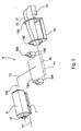
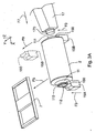
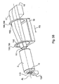
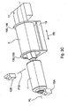
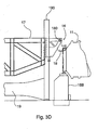
- Figures 3 , 3A-3D show the unmould station of an embodiment of a plant for manufacturing shell structures according to the present invention, in various instants of its operation.
- the reference 11 refers to a supporting structure having a substantially cylindrical shape, and referred to as "molding drum” 11; in a cross-linking station or “baking station " -not shown-, the raw shell 2 has been formed on the flanks of the molding drum, by causing the synthetic resin, of which the raw shell 2 is made, to cross-link.
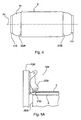
- the molding drum 11 is shown in detail in Figure 4 : in the present embodiment, the drum 11 is provided at its ends with the supports 110, 111, which also have a substantially cylindrical shape and a diameter smaller than the diameter of the central part of the drum 11.
- the molding drum reaches the unmould station 9 transported on a self moving carriage 7, which can be for example a remotely controlled base or an automatic drive base (AGV).
- a self moving carriage 7 which can be for example a remotely controlled base or an automatic drive base (AGV).
- AGV automatic drive base
- the unmould station 9 comprises the displaceable supports 11, arranged for moving on the floor of the station and provided, in their upper part, with a cradle-shaped support zone 150, in its turn arranged for receiving and raising the end supports 110, 111 of drum 11, holding them in a stable position ( Figure 4 ).
- the unmould station 9 further comprises a so-called "expeller strut" 13, comprising a fixed beam 17 horizontally cantilevered and fixed to the fixed base 10.
- a coupling drum device 16 is arranged on the free end of beam 17, arranged for coupling the end supports 110 or 111 of the drum 11 both by supporting the latter vertically and by blocking its horizontal displacements.
- the drum coupling device 16 of Figure 3D comprises a mobile hooking tooth 18 that can rotate around the hinge 180; accordingly the end supports 110, 111 are provided in their inside with suitable inner teeth or flanges, with which the mobile hooking tooth 18 can engage.
- a shell handling carriage 19 is further shown, used for removing the raw shell 2 from the drum 11, removing the raw shell 2 from the unmould station 9 and handling it at the working stations downstream.
- the shell handling carriage 19 is a self-moving carriage, controlled by a remote or automatic control, and provided with two annular structures 190 which will be described later on in deeper detail.
- Each annular structure 190 defines internally a fixing opening 192 arranged so that the raw shell 2 can pass through it.
- the axial distance between the two annular structures 190 is such to allow both the annular structures 190 be positioned at the same time by the end edges 20A, 20B ( Figure 4 ) of the cylindrical shell 2, causing the shell handling carriage 19 to translate parallel to the axis AM of the drum (see arrow F8 in Figure 3B ).
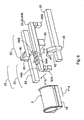
- a plurality of blocking grippers 194 is arranged ( Figure 5 ), for gripping and holding a portion of the end edges 20A, 20B of the cylindrical shell 2.
- the structure and the kinematics of one of such grippers are the following.
- a gripper 194 can be fixed - for example bolted- to one of the annular beams 196 through the fixing plate or fixing frame 198, and positioned in the space so that, in the triad of the cartesian axes R, T, X of Figure 5 , the X-axis corresponds to the X-axis of Figure 3A , and the axs R and T correspond to the radial and tangential directions respectively of the annular beam 196 and of the fixing opening 192 in the point in which the gripper 194 is set.
- a movable base 200 is hinged to the fixing frame 198 so as to be able to rotate around the rotation axis AM1 in the directions indicated by arrow FM1, thanks to the hinges 204.
- the rotation axis AM1 is parallel to the plan in which the fixing plate or fixing frame 198 lies, and is also parallel to the T axis of the triad of reference axes R, T, X of Figure 5 ).
- a fixed jaw 208 and a movable jaw 210 of the gripper are fixed on the movable base 200.
- the opening and the closing of the gripper 194 are driven by the determined from the rotation + translation movements of the movable jaw 210 in the plane RX, so as to be able to clamp the thickness of the external cylindrical wall of the shell 2; for example such rotation + translation movements can be made with a first toggle mechanism.
- the gripper 194 can be provided for example with two jaws, both of them movable.
- the pneumatic cylinder 207 - the assembly of the fixed jaw 208 and the movable jaw 210 can translate parallel to the R axis (arrow FM3).
- each ring-like beam 196 a set of about forty of blocking grippers 194 are arranged, oriented according to the radial directions R of the beam 196 itself.
- the rotation of the movable base 200 around the rotation axis AM1 is driven by a toggle mechanism 202 ( Figure 5 ).
- the pneumatic cylinder 207 is provided with a stem-blocking device, or with another system able of keeping the cylinder blocked in a predetermined linear position even when the cylinder is disconnected from the feeding pneumatic circuit.
- the movements of closing and opening the movable jaw 210 are driven by a second toggle mechanism (not shown).
- An advantage provided by the two aforesaid toggle mechanisms and the stem-blocking device, or another system able of keeping the cylinder 207 blocked in a predetermined linear position, is that a shell structure 2 can be kept clamped and blocked on a shell handling carriage 19 even when the latter is disconnected from its feeding pneumatic -or fluidic- circuit, such as a compressed air circuit, as it happens in the present embodiment during several steps of handling the shells 2.
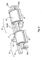
- Figures 6-10 show the rib assembling station 20, where the holed are made, for riveting the cross-sectional strengthening ribs 3 to the cylindrical shell 2.
- the rib assembling station 20 comprises a central or internal guide 22 and two side- or external guides 24, 26, parallel one with another.
- the internal guide 22 comprises a carrying beam 28 - also referred to as, in the present description, "central beam” - supported by a fixed central support 30 - arranged at about half of the length of the central beam 28 - and by two displaceable supports 32A, 32B arranged at the two ends of the central beam 28.
- anthropomorphic robots 34A, 34B are set on the internal guide 22 so as to be able to slide along the guide itself yarrow F12 in Figure 6 ), while on each one of the external guides 24, 26 movable tower -36, 38 respectively- is set, slidable along its respective guide 24, 26.
- an anthropomorhic robot - 40, 42 respectively- is set, referred to as “external robot” 40, 42 respectively in the present description.
- the four robots are arranged to be able to work simultaneously, and the external robots 40, 42 are provided with drilling heads - for example of the type described in the patent application N° TO2002A000030, filed on 11/01/2002 by one of the applicants/assignees of the present application, while the task of the internal robots 34A, 34B is mainly providing a rigid support for the shell 2 during the drilling, in the zone in which the external robot 40 or 42 is drilling.
- the cylindrical shell 2 be drilled with groat precision, even if the shell is quite deformable, like for example in the present embodiment, wherein the shell when is being drilled is made up only of a cylindrical composite material wall having a thickness of about ten millimeters, a diameter of 6 m and a length of 9-16 m.
- the external and internal robots are arranged also for riveting the ribs 3 on the raw shell 2.
- the inner 22 and external guides 24, 26 have such a length to allow two cylindrical shells 2 and two shell handling carriages 19 be slipped on said guides at the same time, in their respective working positions 21, 23 ( Figure 8 ): as it will turn out more clearly from the following description, this concurs to improve the productivity of the plant, and in particular of the internal 34A, 34B and external robots 40, 42.
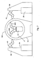
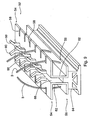
- Figures 9 , 10 show an embodiment of a rib store 52 of a plant according to the present invention.
- the rib store 52 is a mobile structure comprising, in the present embodiment, two upper consoles or balconies 54 and two lower consoles or balconies 56 - on which the personnel can walk.
- the rib store also defines a plurality of rib seats arranged for receiving and to supporting -for example orderly aligned like on a rack ( Figure 9 )- a plurality of transversal add-on or strengthening ribs 3, or parts thereof, waiting for being assembled to the cylindrical shell 2.
- each pair upper balcony 56 + lower balcony 54 is made on a structure 62 having the overall shape of a C-beam.
- the pair of C-beams 62 is set on a driving carriage 64, such as a remote control carriage or an automatic controlled carriage. Between the two C-shaped structures 62 a space is provided, referred to as guide passage seat 66, such as to allow internal guide 22 of working positions 21, 23 be inserted in it.
- FIG 3 schematically shows a first instant of the operation: in such instant the cylindrical shell 2, coming from a cross-linking- or "baking” station (not shown), is transported, in a horizontal or however laying position, on the self-moving carriage 7, towards an unload station indicated with the reference numeral 9.
- the raw shell 2 travels on the carriage 7 still fitted on the support 11.
- Said support 11 has an approximately cylindrical shape and is referred to as "cross-linking drum 11" or simply "drum 11 ".
- the drum 11 is used for forming the raw shell 2 by wrapping carbon fiber fabric onto it and burying the fabric in the synthetic resin, according to a process such as the one described in one of the documents WO2005/018917A2 WO2005/018918A2 or WO2005/082604A2 .
- the carriage 7, together with the drum 11 and the raw shell 2 reaches the position P1 of Figure 2 , so that a) the longitudinal axis AM of the drum is substantially aligned with the strut 13, and b) the end supports 110, 111 of the drum 11 are positioned above the raising supports 15A, 15B, also said, in the present description, "displaceable supports 15A, 15B" ( Figure 3 ).
- the cradles 150 raise (arrows F3 of Figure 3A ) lifting in their turn the drum 11 ( Figure 3A ), so as to allow the carriage 7 be extracted from below the drum 11, and be removed (arrow F5 of Figure 3A ).
- the expeller strut 13 comes closer to and firmly engages the end 111 of the drum 11 moving in a direction parallel to the AL axis of the drum (see arrow F7 of Figure 3A ), supporting the end 111 of the drum as much as to allow the telescopic support 15B, closer to the strut 13, be withdrawn and removed by causing it slide transversally to the drum (see arrow F9 of Figure 3A ).
- the expeller strut 13 makes itself firm and is able to firmly support the end 111 of the drum 11 thanks to telescopic pin 170, which by extending engages a corresponding female seat 112 provided at the 110, 111 of the drum 11.
- both of the annular structures 190 reach the end edges 20A, 20B ( Figure 4 ) of the cylindrical shell 2
- the grippers 194 are driven according to a suitable sequence and clamp the thickness of the end edges 20A, 20B ( Figure 4 ) of the cylindrical shell 2.
- the separation of the drum 11 from the cylindrical shell 2 is also helped by the fact that the middle portion of the drum, on which the shell has been formed, is splitted in a suitable number of gores or sectors (not shown) which can radially expand and retract.
- the shell handling carriage 19 is now used for handling the cylindrical shell 2, which now is accessible also at its inside, during a plurality of following working steps.
- the carriage 19 carries the shell 2 to a measuring station, where a detecting device - for example a laser geometry measurer-maps the whole raw shell 2, detecting among other things the displacements of the reference holes ("DA holes") due to the deformations of the shell 2 following removal of drum 11: in fact the "DA holes" are a set of holes used as reference in all of the following workings, and in the present embodiment had been made beforehand when the raw shell 2 was still inserted on the drum 11.
- a detecting device for example a laser geometry measurer-maps the whole raw shell 2
- DA holes displacements of the reference holes
- the "DA holes" are a set of holes used as reference in all of the following workings, and in the present embodiment had been made beforehand when the raw shell 2 was still inserted on the drum 11.
- the shell handling carriages 19 are provided with a rotary actuator arranged for turning the shell 2 on itself on its longitudinal AL axis: by turning in this way the shell 2, the laser head of the detecting device does not need to be introduced in the space between the lower part of the shell and the bottom of the ring carriage 19, thereby avoiding the problems with the overall dimensions and the passing of the laser head relating thereto; furthermore the laser scan head does not even need to be mounted on an articulated arm, avoiding thereby the precision losses of precision due to such arm.
- the aforesaid rotary actuator arranged for rotating the shell 2 on its longitudinal AL axis, can be blocked in a predetermined position also when pneumatic, fluidic or electric supply is lacking: this allows a shell structure 2 be kept clamped and fixed in a determined position on a shell handling carriage 19 also when the carriage 19 is disconnected from its pneumatic -or fluidic, or electric- supply circuit, for example from a compressed air circuit, as it happens in the present embodiment during several steps of the handling of shells 2.
- the carriage 19 carries the shell 2 to the rib assembling station, shown in Figures 6 , 7 and indicated with the overall reference 20: in such station the holes are made, for riveting the transversal strengthening ribs 3 to the cylindrical shell 2, with the following process.
- the displaceable support 32A moves to one side (arrow F16 of Figure 6 laterally) so as to allow the shell handling carriage 19 be fitted onto the cantilevered end of the central beam 28 in the inner cavity of the tubular shelf 2 ( Figure 7 ).
- the shell handling carriage 19 keeps sliding along the internal guide 22 until it reaches the correct working position, at which it stops and is blocked by suitable lockings, such as mechanic lockings.
- the driving carriage 64 which previously was supplying the shell handling carriage 19 with the motive power so as to move it, separates from the shell handling carriage itself and leaves the rib assembling station 20 (arrow F20 of Figure 6A ); the displaceable support 32A remains displaced at a side so as to allow the driving carriage 46 to pass.
- the displaceable support 32A positions itself again below the end 44A of the central beam 28 with an lateral movement opposite to the previous one (see arrow F18 of Figure 6A ), so as to support the central beam 28 again.
- the internal 34A, 34B and external robots 40, 42 drill the holes in the cylindrical shell 2 for allowing the transversal add-on ribs or strengthening ribs 3 be fixed to the shell.
- the internal robots 34A, 34B operate inside of the cylindrical shell 2, while at the same time the external robots 40, 42 operate outside.
- the robots 34A, 34B, 40, 42 leave the only just drilled shell 2 and move -by simply translating along their respective guides 22, 24, 26- on the second working position 23 of the rib assembling station 20 ( Figures 6 , 8 ); on the station 20 the robots 34A, 34B, 40, 42 can for example perform drilling workings, such as the ones just described, on a second cylindrical shell 2A, or the riveting workings as described later on.
- the rib store 52 driven by the driving carriage 64 is fitted over the internal guide 22 from the side of position 21; in order to be able to do that, the displaceable support 32A in the present embodiment is displaced at a side (arrow F16 of Figure 6 ).
- the rib store 52 is then caused to slide along the internal guide 22 until it enters the fixed cylindrical shell 2 on one of the shell handling carriages 19 ( Figure 10 ).
- the personnel can now go on the upper 54 or lower balconies 56, depending on the need, and start assembling the add-on ribs 3 on the shell 2 from the inside; thanks to the orderly arrangement of the add-on ribs 3 on the seats of the rib store 52, the personnel can take each add-on rib from its seat 58, 60 and assemble it on the facing portion of the shell 2.
- the personnel fastens temporarily the add-on ribs 3 to the shell 2 with some temporary studs or rivets, for example two of them.
- the rib store 52 is removed from the internal guide 22 and evacuated from the working position 21.
- the robots 34A, 34B, 40, 42 move again to the working position 21 and rivet the transversal add-on ribs 3 on the cylindrical shell 2.
- an example of rivet is shown, known per se, suitable for such riveting.
- the external robots 40, 42 insert a rivet of the kind of Figure 11 from the outside of the shell 2; thereafter the internal robots 34A, 34B pull the threaded end 72 of the rivet 70 until stripping it off, and fit the blocking bushing 74, per se known.
- the cylindrical shells 2 remain motionless at the working position 21 or 23 during the three operations of drilling, provisionally and definitively riveting the add-on ribs, and the robots 34A, 34B, 40, 42 are moved which have much smaller dimensions.
- the rib stores 52 are moved, which have dimensions and weight comparable with the assemblies shell 2 + shell handling-carriage 19, but for drilling/provisionally riveting/definitively riveting each barrel a single no store is moved only once.
- rib stores 52 provides the advantages, already set forth above, that the manual positioning and assembling of the different add-on ribs on the cylindrical shell 2 is much quicker, and the risk of errors, such as positioning a wrong rib 3 in a predetermined portion of the shell 2, is greatly reduced. Moreover, a great number and choice of ribs can be brought to the barrel to be assembled with only one travel of the rib store 52.
- the working method and the devices according to the present invention can be adapted for manufacturing barrels having a semi-cylindrical or semitubular shape -such as the one shown in Figure 2 - frustum conical or in general of a concave and/or convex shell.
- the shell handling carriages 19 can be provided with a plurality of blocking grippers 194 arranged for gripping not only the end edges 20A', 20B' but also the side edges 68 ( Figure 2 ) of the semi-cylindrical shell 2 '.
- the internal 34A, 34B and external robots 40, 42 can be replaced, more generally, with one or more internal working carriages 34A, 34B and with one or more external working carriages 40, 42 respectively, installed so as to be able to slide on the internal guide 22 and on the external guides 24, 26 respectively.
- the anthropomorphic robots 34A, 34B, 40, 42 can also be replaced with other kinds of mechanical arms.
- the number of the internal robots 34A, 34B, or external robots 40, 42, can also differ from two.
- the expressions "cylindrical”, “conical” and “frustumconical” referred to the shell 2 and/or to the barrel 1 are to be understood as including prism-, pyramid- and pyramid section shapes respectively.
- the toggle mechanism 202 the device for blocking the stem of the pneumatic cylinder 207 ( Figure 5 ) and the toggle mechanism causing the movable jaw 210 to close or to open, and more generally the mechanism of the blocking gripper 194, can be replaced for example with lead screw + nut thread systems, bistable systems or still other drives, arranged for remaining blocked in a predetermined locking-, unlocking or positioning condition even without power supply from a pneumatic -e.g. compressed air-, fluidic, electric power supply circuit etcetera.
- a pneumatic -e.g. compressed air-, fluidic, electric power supply circuit etcetera arranged for remaining blocked in a predetermined locking-, unlocking or positioning condition even without power supply from a pneumatic -e.g. compressed air-, fluidic, electric power supply circuit etcetera.
Landscapes
- Engineering & Computer Science (AREA)
- Transportation (AREA)
- Manufacturing & Machinery (AREA)
- Aviation & Aerospace Engineering (AREA)
- Automatic Assembly (AREA)
- Tyre Moulding (AREA)
- Fertilizers (AREA)
- Artificial Fish Reefs (AREA)
Claims (32)
- Verfahren zur Herstellung einer Schalenstruktur, das folgende Schritte umfasst:- Bereitstellen einer Ausgangsschale (2, 2'), die mit einer Vielzahl von Verstärkungsrippen (5), die in einer ersten festgelegten Richtung (AL) ausgerichtet sind, und mit mindestens einem Rand (20A, 20B, 20A', 20B') versehen ist;- Anordnen einer Querverstärkungsrippe (3) an der Ausgangsschale, sodass die Querverstärkungsrippe (3) quer zu den Verstärkungsrippen (5) verläuft, die in der ersten festgelegten Richtung (AL) ausgerichtet sind, um die Ausgangsschale zumindest hinsichtlich der Drücke, die zum Verformen ihrer Wölbungen neigen, zu verstärken,
gekennzeichnet durch den weiteren Schritt des- Bereitstellens einer Greifvorrichtung, die einen Handhabungsschlitten (19) umfasst, und mindestens eines Arretierungsgreifers (194), der dem Handhabungsschlitten (19) zugehörig ist, wobei die Greifvorrichtung zum Greifen des mindestens einen Rands (20A, 20B, 20A', 20B') angeordnet ist. - Verfahren nach Anspruch 1, wobei die Ausgangsschale (2, 2') mindestens eine konkave Wand definiert.
- Verfahren nach Anspruch 1 oder 2, wobei die Ausgangsschale (2, 2') eine konkave Wand definiert und wobei der Schritt des Bereitstellens der Greifvorrichtung folgende Schritte umfasst:- Bereitstellen der Ausgangsschale (2, 2') mit der konkaven Wand, die an einem Formzylinder (11) befestigt ist;- Greifen des Rands (20A, 20B, 20A', 20B') der Ausgangsschale (2, 2') mit dem mindestens einen Arretierungsgreifer (194);- Entfernen der Ausgangsschale (2, 2') von dem Formzylinder (11) mittels der Greifvorrichtung.
- Verfahren nach einem der Ansprüche 1 bis 3, umfassend den Schritt des Greifens des Rands (20A, 20B, 20A', 20B') der Ausgangsschale durch Festklemmen desselben mittels des mindestens einen Arretierungsgreifers (194) in der Richtung der Dicke.
- Verfahren nach Anspruch 3, wobei die Ausgangsschale (2, 2') eine im Wesentlichen röhrenartige Form aufweist und einen inneren Durchgangshohlraum (50) definiert, und das Verfahren ferner den Schritt des Entfernens der Ausgangsschale (2, 2') von dem Formzylinder (11) durch Drücken des letzteren gegen das freie Ende eines Ausschubglieds (13) umfasst.
- Verfahren nach Anspruch 5, das den Schritt des Durchführens von einem oder mehreren der folgenden Schritte mit zwei mechanischen Gelenkarmen (34A, 34B, 40, 42) umfasst: Bohren der Ausgangsschale (2, 2'), Nieten, Schrauben, Kleben, Schweißen, Anordnen einer Verstärkungsrippe (3) an der Ausgangsschale (2, 2'), wobei ein erster der mechanischen Arme in dem inneren Durchgangshohlraum (50) der Ausgangsschale (2, 2') arbeitet und ein zweiter der beiden mechanischen Arme außerhalb der Ausgangsschale (2, 2') arbeitet.
- Greifvorrichtung zur Herstellung von Schalenstrukturen (1, 1'), die eine Ausgangsschale (2, 2') mit mindestens einem Rand (20A, 20B, 20A', 20B') umfassen, wobei die Greifvorrichtung einen Handhabungsschlitten (19) und mindestens einen Arretierungsgreifer (194), der dem Handhabungsschlitten (19) zugehörig ist, umfasst, wobei die Greifvorrichtung dadurch gekennzeichnet ist, dass der mindestens eine Arretierungsgreifer (194) zum Greifen der Ausgangsschale (2, 2') durch Greifen des mindestens einen Rands (20A, 20B, 20A', 20B') angeordnet ist.
- Vorrichtung nach Anspruch 7, umfassend eine Fixieröffnung (192), die so angeordnet ist, dass die Schale (2) sie durchqueren kann, wobei um die und/oder nahe der Fixieröffnung (192) eine Vielzahl von Arretierungsgreifern (194) angeordnet ist, um die Ausgangsschale (2, 2'), die auf die Vorrichtung selbst geladen ist, durch Greifen von zumindest einem Teil des Rands (20A, 20B, 20A', 20B') der Schale (2) zu fixieren.
- Vorrichtung nach einem der Ansprüche 7 oder 8, umfassend ein sich drehendes Stellglied, das dem Handhabungsschlitten (19) zugehörig ist und angeordnet ist, um eine Ausgangsschale (2) um sich selbst zu drehen, wobei die Ausgangsschale (2) auf die Greifvorrichtung (194) selbst geladen und mit den Arretierungsgreifern (194) arretiert ist.
- Vorrichtung nach einem der Ansprüche 7 bis 9, wobei der Handhabungsschlitten (194) ferner mit zwei ringförmigen Strukturen (190) versehen ist, von denen jede eine Fixieröffnung (192) definiert, die so angeordnet sind, dass die Ausgangsschale (2, 2') sie durchqueren kann.
- Vorrichtung nach einem der Ansprüche 7 bis 10, wobei der mindestens eine Arretierungsgreifer (194) ein Fixiergestell (198), das an der ringförmigen Struktur (190) befestigt ist, eine bewegliche Basis (200), die gelenkig so an dem Fixiergestell (198) befestigt ist, dass sie sich um eine Drehachse (AM1) drehen kann, die parallel zu der Ebene verläuft, in der das Fixiergestell (198) liegt, und zu einer Tangentialrichtung (T), die bezogen auf die ringförmige Struktur (190) definiert ist, umfasst.
- Vorrichtung nach Anspruch 11, wobei die bewegliche Basis (200) angeordnet ist, um sich auf eine von einem Kniehebelmechanismus (202) angetriebene Art und Weise um die Drehachse (AM1) zu drehen.
- Vorrichtung nach Anspruch 11 oder 12, wobei der mindestens eine Arretierungsgreifer (194) ein Paar Backen (208, 210) umfasst, die an der beweglichen Basis (200) befestigt sind, wobei mindestens eine der Backen eine bewegliche Backe (210) ist.
- Vorrichtung nach Anspruch 13, wobei der mindestens eine Arretierungsgreifer (194) Gleitführungen (206) und ein Stellglied (207) umfasst, wobei sich die Anordnung, die aus den Backen (208, 210) gebildet ist, entlang einer Translationsrichtung (FM3) parallel zu einer Radialrichtung (R), die bezogen auf die ringförmige Struktur (190) definiert ist, linear bewegen kann.
- Vorrichtung nach Anspruch 14, wobei das Stellglied ein Pneumatikzylinder (207) ist, der mit einem System ausgestattet ist, das dazu angeordnet ist, den Zylinder (207) in einer festgelegten linearen Position arretiert zu halten, wenn der Zylinder (207) von dem Versorgungspneumatikkreislauf desselben getrennt ist.
- Vorrichtung nach Anspruch 13 bis 15, wobei die mindestens eine bewegliche Backe (210) angeordnet ist, sich in einer Ebene, die durch eine radiale Richtung (R) und eine Mittenrichtung (X) definiert ist, die bezogen auf die ringförmige Struktur (190) definiert sind, zu drehen und geradlinig zu bewegen, um die Ausgangsschale (2, 2') in Richtung der Dicke festklemmen zu können.
- Vorrichtung nach einem der Ansprüche 13 bis 16, wobei der mindestens eine Arretierungsgreifer (194) angeordnet ist, auf eine durch die Dreh- und Linearbewegungen, die von der beweglichen Backe (210) ausgeführt werden, angetriebene Art und Weise geöffnet und geschlossen zu werden.
- Vorrichtung nach Anspruch 17, wobei die bewegliche Backe (210) von einem weiteren Kniehebelmechanismus angetrieben ist.
- Vorrichtung nach einem der Ansprüche 11 bis 18, wobei an jeder der ringförmigen Strukturen (190) der mindestens eine Arretierungsgreifer (194) angeordnet ist.
- Anlage zum Bearbeiten von Schalenstrukturen (1, 1'), die eine Ausgangsschale (2, 2') mit einer im Wesentlichen röhrenartigen Form und einen Formzylinder (11) umfassen, der in dem inneren Durchgangshohlraum (50) der Ausgangsschale (2, 2') eingepasst ist, wobei die Anlage Folgendes umfasst:- eine Greifvorrichtung nach einem der Ansprüche 7 bis 19, wobei die Vorrichtung zum Befördern der Anordnung von Formzylinder (11) + Ausgangsschale (2, 2') zur Anlage selbst und zum Entnehmen der Anordnung (11, 2, 2') aus der Anlage selbst angeordnet ist,- ein Ausschubglied (13), der einen Balken (17) umfasst, der mit einem freien Ende versehen und angeordnet ist, die Ausgangsschale (2, 2') vom Formzylinder (11) zu entfernen,- ein Paar verschiebbarer Träger (15A, 15B), die zum Anordnen der Anordnung von Formzylinder (11) + Ausgangsschale (2) längs zum Balken (17) des Ausschubstabs (13) und im Wesentlichen vor dem freien Ende des Balkens (17) angeordnet sind.
- Anlage nach Anspruch 20, wobei:- die Greifvorrichtung angeordnet ist, die Anordnung von Formzylinder (11) + Ausgangsschale (2, 2') zur Anlage selbst zu transportieren und die Anordnung aus der Anlage zu entnehmen, indem die Anordnung (11, 2, 2') in einer im Wesentlichen waagerechten oder liegenden Position transportiert wird,- die verschiebbaren Träger (15A, 15B) angeordnet sind, die beiden Enden der Anordnung von Formzylinder (11) + Ausgangsschale (2, 2') zu tragen,- das Ausschubglied (13) einen einseitig eingespannten Balken (17) umfasst, der im Wesentlichen in einer waagerechten Richtung verläuft.
- Anlage nach Anspruch 20 oder 21, die ein Greif- und Handhabungssystem umfasst, das zum Greifen der Schale (2) und zum Transportieren derselben vom Formzylinder (11) am Ausschubglied (13) angeordnet ist.
- Anlage nach einem der Ansprüche 20 bis 22, wobei die Anordnung von Formzylinder (11) + Ausgangsschale (2) zwei Enden (110, 111) definiert und mindestens einer der verschiebbaren Träger (15A, 15B) angeordnet ist, um ein Ende (110, 111) der Anordnung von Formzylinder (11) + Ausgangsschale (2) anzuheben und/oder abzusenken.
- Anlage nach einem der Ansprüche 20 bis 23, die einen Formzylinder (11) umfasst, der zwei Enden (110, 111) definiert und angeordnet ist, eine Ausgangsschale (2, 2') an sich selbst zu befestigen, wobei eins der Enden (110, 111) des Formzylinders und das einseitig eingespannte Ende des Ausschubglieds (13) angeordnet sind, ineinander einzugreifen, um den Formzylinder (11) in einer im Wesentlichen waagerechten Position zu halten, wobei ein Ende (111) des Zylinders (11) von dem einseitig eingespannten Ende des Ausschubglieds gehalten wird und das andere Ende (110) auf einem der verschiebbaren Träger (15A, 15B) aufliegt.
- Anlage zum Bearbeiten von Schalenstrukturen (1, 1'), die eine Ausgangsschale (2, 2') mit mindestens einem Rand (20A, 20B, 20A', 20B') umfassen, wobei die Anlage (20) Folgendes umfasst:- eine innere Führung (22),- eine äußere Führung (24, 26), die auf einer Seite der inneren Führung angeordnet ist,- einen inneren Arbeitsschlitten (34A, 34B), der an der inneren Führung (22) montiert ist, um sie entlang gleiten zu können,- einen äußeren Arbeitsschlitten (36, 38), der an der äußeren Führung (24, 26) montiert ist, um sie entlang gleiten zu können, wobei der äußere Arbeitsschlitten (36, 38) und/oder der innere Arbeitsschlitten (34A, 34B) angeordnet ist bzw. sind, Arbeiten an der Ausgangsschale (2, 2') auszuführen,- eine Greifvorrichtung nach einem der Ansprüche 7 bis 19, wobei die Vorrichtung zum Handhaben der zu bearbeitenden Ausgangsschale (2, 2') bezogen auf die innere (22) und/oder äußere Führung (24, 26) und zum Tragen derselben in einer festgelegten Arbeitsposition (21, 23) angeordnet ist, in der sie von dem äußeren Arbeitsschlitten (36, 38) und/oder dem inneren Arbeitsschlitten (34A, 34B) bearbeitet werden kann.
- Anlage nach Anspruch 25, wobei die zu bearbeitende Ausgangsschale (2, 2') eine Außenseite und eine Innenseite gegenüber der Außenseite definiert und wobei die Anlage so angeordnet ist, dass der innere Arbeitsschlitten (34A, 34B) an der Innenseite der Schale (2, 2') eine Arbeit ausführen und/oder auf sie einwirken kann und der äußere Arbeitsschlitten (36, 38) an der Außenseite der Schale (2, 2') eine Arbeit ausführen und/oder auf sie einwirken kann.
- Anlage nach Anspruch 25 oder 26, wobei der äußere Arbeitsschlitten (36, 38) und/oder der innere Arbeitsschlitten (34A, 34B) einen mechanischen Gelenkarm umfasst bzw. umfassen.
- Anlage nach einem der Ansprüche 25 bis 27, wobei von dem äußeren Arbeitsschlitten (36, 38) und dem inneren Arbeitsschlitten (34A, 34B) mindestens einer (34A, 34B; 36, 38) angeordnet ist, eine Arbeit an der zu bearbeitenden Ausgangsschale (2, 2') auszuführen, und der andere (36, 38; 34A, 34B) von dem äußeren Arbeitsschlitten und dem inneren Arbeitsschlitten angeordnet ist, an der zu bearbeitenden Ausgangsschale (2, 2') anzuliegen, um deren Verformungen und/oder die Verschiebungen während der Arbeit des äußeren Arbeitsschlittens und/oder des inneren Arbeitsschlittens zu verhindern oder einzuschränken.
- Anlage nach einem der Ansprüche 25 bis 28, die ein Führungsträgersystem (30, 32A, 32B) umfasst, um ein Ende (44A, 44B) der inneren Führung (22) und/oder der äußeren Führung (24, 26) zumindest vorübergehend wie einen Ausleger zu fixieren, damit dieses Ende (44A, 44B) zumindest vorübergehend wie ein Ausleger in den inneren Durchgangshohlraum (50) der Ausgangsschale (2, 2') gesteckt werden kann.
- Ausrüstung zum Bearbeiten von Schalenstrukturen (1, 1'), die eine Ausgangsschale (2, 2') umfassen, wobei die Ausrüstung eine Greifvorrichtung nach einem der Ansprüche 7 bis 19 umfasst und einen Rippenvorrat (52), der mit einer Vielzahl von Rippenaufnahmen (58, 60) versehen ist, von denen jede zum Aufnehmen und Platzieren einer Verstärkungsrippe (3) angeordnet ist, die an einer Ausgangsschale (2, 2') anzubringen ist, um einen Abschnitt eines Flugzeugrumpfs bereitzustellen, und ferner mit einer Konsole, einem Gang (54, 56) oder einem anderen erhöhten Boden versehen ist, über den das Personal die Vielzahl der Rippenaufnahmen (58, 60) erreichen kann.
- Ausrüstung nach Anspruch 30, wobei die Vielzahl von Rippenaufnahmen (58, 60) auf zwei Seiten des Rippenvorrats (52) einander gegenüber ausgerichtet ist, um zwei Reihen der Aufnahmen zu bilden.
- Anlage zum Bearbeiten von Schalenstrukturen, die eine Anlage nach Anspruch 20 bis 29 und eine Ausrüstung nach Anspruch 30 oder 31 umfasst, wobei die Ausrüstung eine Führungsdurchgangsaufnahme (66) definiert, die zwischen den beiden Reihen der Rippenaufnahmen (58, 60) angeordnet ist, wobei die Führungsdurchgangsaufnahme (66) angeordnet ist, die innere Führung (22) und/oder die äußere Führung (24, 26) aufzunehmen, damit die Führung (22, 24, 26) zwischen den beiden Reihen der Rippenaufnahmen (58, 60) verschoben werden kann.
Applications Claiming Priority (2)
| Application Number | Priority Date | Filing Date | Title |
|---|---|---|---|
| IT000518A ITTO20060518A1 (it) | 2006-07-14 | 2006-07-14 | Metodo, attrezzatura e impianto per la lavorazione di strutture a guscio |
| PCT/IB2007/052781 WO2008010159A2 (en) | 2006-07-14 | 2007-07-12 | Method, apparatus and plant for manufacturing shell structures |
Publications (2)
| Publication Number | Publication Date |
|---|---|
| EP2040979A2 EP2040979A2 (de) | 2009-04-01 |
| EP2040979B1 true EP2040979B1 (de) | 2012-08-08 |
Family
ID=38957167
Family Applications (1)
| Application Number | Title | Priority Date | Filing Date |
|---|---|---|---|
| EP07825918A Not-in-force EP2040979B1 (de) | 2006-07-14 | 2007-07-12 | Verfahren, vorrichtung und anlage zur herstellung von muschelstrukturen |
Country Status (9)
| Country | Link |
|---|---|
| US (1) | US8403201B2 (de) |
| EP (1) | EP2040979B1 (de) |
| CN (1) | CN101506033B (de) |
| BR (1) | BRPI0713240B1 (de) |
| CA (1) | CA2657372C (de) |
| ES (1) | ES2392556T3 (de) |
| IT (1) | ITTO20060518A1 (de) |
| RU (1) | RU2448876C2 (de) |
| WO (1) | WO2008010159A2 (de) |
Families Citing this family (16)
| Publication number | Priority date | Publication date | Assignee | Title |
|---|---|---|---|---|
| ITTO20060581A1 (it) | 2006-08-04 | 2008-02-05 | Bruno Bisiach | Dispositivo e metodo di lavorazione di un pezzo da lavorare, quale per esempio una struttura a guscio di un velivolo |
| CN102030110B (zh) * | 2010-10-25 | 2013-03-20 | 北京航空航天大学 | 一种防干涉飞机机身、机翼交点对合加工夹具装置 |
| US9090357B2 (en) * | 2011-12-15 | 2015-07-28 | The Boeing Company | Method of assembling panelized aircraft fuselages |
| US9102019B2 (en) * | 2012-12-21 | 2015-08-11 | Embraer S.A. | Process for joining aircraft structural components |
| DE102013006506A1 (de) * | 2013-04-16 | 2014-10-16 | Brötje-Automation GmbH | Bearbeitungsanlage für Flugzeugstrukturbauteile |
| US9370827B2 (en) * | 2013-08-28 | 2016-06-21 | The Boeing Company | System and method for forming perforations in a barrel section |
| US9937549B2 (en) | 2014-07-09 | 2018-04-10 | The Boeing Company | Two-stage riveting |
| US10815679B2 (en) * | 2017-01-27 | 2020-10-27 | The Boeing Company | System for four collaborative robots and humans in a narrowing work envelope |
| FR3072656B1 (fr) * | 2017-10-24 | 2019-11-08 | Airbus | Systeme d’outillage destine a la manipulation d’au moins un module superieur et /ou au moins un module inferieur. |
| FR3075168B1 (fr) * | 2017-12-19 | 2019-11-15 | Airbus Operations (S.A.S.) | Fond etanche a partie semi-cylindrique et partie avant d'aeronef pourvu d'un tel fond |
| US10675768B2 (en) | 2018-03-27 | 2020-06-09 | The Boeing Company | Robotic end effector assembly, system, and method of using the same |
| US11724346B2 (en) * | 2020-11-18 | 2023-08-15 | The Boeing Company | Moving line assembly of airframes |
| RU2755229C1 (ru) * | 2021-01-28 | 2021-09-14 | Акционерное общество «Научно-производственная корпорация «Уралвагонзавод» имени Ф.Э. Дзержинского» | Устройство для сборки под сварку бандажей с обечайками |
| ES3013507T3 (en) * | 2021-07-15 | 2025-04-14 | Airbus Operations Slu | Method for the assembly of frames in an aircraft shell |
| CN115610617B (zh) * | 2022-10-13 | 2025-03-25 | 武汉船用机械有限责任公司 | 一种悬臂结构件的制造方法及悬臂结构件 |
| CN119839527B (zh) * | 2025-03-21 | 2025-09-09 | 成都飞机工业(集团)有限责任公司 | 一种自动转运系统 |
Family Cites Families (30)
| Publication number | Priority date | Publication date | Assignee | Title |
|---|---|---|---|---|
| US1922063A (en) | 1931-05-01 | 1933-08-15 | Curtiss Aeroplane & Motor Co | Monocoque body |
| US2974217A (en) * | 1959-01-07 | 1961-03-07 | Thomas J Crawford | Method and apparatus for electric welding pipe and the like |
| JPS5339972Y2 (de) * | 1973-09-14 | 1978-09-27 | ||
| US4145593A (en) * | 1976-02-03 | 1979-03-20 | Merrick Welding International, Inc. | Automatic pipe welding system |
| US4039115A (en) * | 1976-06-01 | 1977-08-02 | Acf Industries, Incorporated | Apparatus for obtaining abutting contact of hollow tank courses to be circumferentially welded |
| US4190184A (en) * | 1978-08-23 | 1980-02-26 | Libbey-Owens-Ford Company | Method of and apparatus for thermally cutting glass |
| US4565003A (en) * | 1984-01-11 | 1986-01-21 | Phillips Petroleum Company | Pipe alignment apparatus |
| JPS6399915A (ja) | 1986-10-17 | 1988-05-02 | Agency Of Ind Science & Technol | 樹脂系複合材料製品成形用の可撓性マンドレル |
| JP2935722B2 (ja) * | 1990-02-28 | 1999-08-16 | 富士重工業株式会社 | 航空機の胴体構造およびその成形方法 |
| SU1798990A1 (ru) * | 1990-10-30 | 1996-05-10 | Таганрогское авиационное производственное объединение | Устройство для сборки узлов летательных аппаратов |
| US5560102A (en) * | 1992-10-13 | 1996-10-01 | The Boeing Company | Panel and fuselage assembly |
| CN2154974Y (zh) * | 1993-05-26 | 1994-02-02 | 江照政 | 排油烟机外壳连接结构 |
| EP0803313A3 (de) * | 1996-04-23 | 2000-01-12 | Daido Tokushuko Kabushiki Kaisha | Verfahren und Vorrichtung zum Diffusionsschweissen |
| US5685996A (en) * | 1996-05-20 | 1997-11-11 | Ricci; Donato L. | Plasma arc pipe cutting apparatus |
| US6032343A (en) * | 1997-02-24 | 2000-03-07 | Ethicon, Inc. | Automated swage wind and packaging machine |
| JP3740000B2 (ja) * | 1999-07-23 | 2006-01-25 | 三菱重工業株式会社 | タイヤ成形装置 |
| NL1013477C2 (nl) * | 1999-11-03 | 2001-05-04 | Vermaat Technics Bv | Werkwijze en inrichting voor het lassen van pijpen. |
| EP1127663A1 (de) * | 2000-01-26 | 2001-08-29 | TELEFONAKTIEBOLAGET LM ERICSSON (publ) | Greifvorrichtung |
| JP4318381B2 (ja) | 2000-04-27 | 2009-08-19 | 本田技研工業株式会社 | 繊維強化複合材からなる胴体構造体の製造方法、及びそれにより製造される胴体構造体 |
| US6578247B2 (en) * | 2000-08-31 | 2003-06-17 | International Truck Intellectual Property Company, Llc | Vehicle chassis inverter |
| DE10122092A1 (de) | 2001-05-07 | 2002-11-21 | Mechanik Ct Erlangen Gmbh | Bearbeitungsvorrichtung für ein Rumpfelement eines Luftfahrzeugs, insbesondere eines Hubschraubers |
| US7188879B2 (en) * | 2001-11-06 | 2007-03-13 | Phd, Inc. | Slide gripper assembly |
| ES2251270B1 (es) | 2002-11-21 | 2007-06-16 | Manuel Torres Martinez | Sistema de ensamblaje del fuselaje de aeronaves. |
| US6942139B2 (en) * | 2003-04-29 | 2005-09-13 | Lincoln Global, Inc. | Robotic cylinder welding |
| DE202004020404U1 (de) * | 2003-06-05 | 2005-05-25 | Langenstein & Schemann Gmbh | Handhabungsgerät zum Handhaben eines Werkstücks während eines Umformprozesses |
| US7527222B2 (en) | 2004-04-06 | 2009-05-05 | The Boeing Company | Composite barrel sections for aircraft fuselages and other structures, and methods and systems for manufacturing such barrel sections |
| US7624488B2 (en) | 2004-12-07 | 2009-12-01 | The Boeing Company | One-piece barrel assembly cart |
| AT501244B1 (de) * | 2004-12-29 | 2007-10-15 | Sticht Fertigungstech Stiwa | Verfahren zur herstellung einer baugruppe aus mehreren miteinander gefügten teilen |
| DE102005027986B4 (de) * | 2005-06-16 | 2008-06-05 | Thyssenkrupp Drauz Nothelfer Gmbh | Verfahren und Anlage zum Zusammenbauen von Bauteilen einer Fahrzeugkarosserie |
| FR2907698B1 (fr) * | 2006-10-26 | 2009-07-03 | Aro Soc Par Actions Simplifiee | Gamme de pinces a enserrer des toles a batis semblables,et de preference identiques,et pince d'une telle gamme. |
-
2006
- 2006-07-14 IT IT000518A patent/ITTO20060518A1/it unknown
-
2007
- 2007-07-12 RU RU2009105070/11A patent/RU2448876C2/ru not_active IP Right Cessation
- 2007-07-12 US US12/307,850 patent/US8403201B2/en not_active Expired - Fee Related
- 2007-07-12 ES ES07825918T patent/ES2392556T3/es active Active
- 2007-07-12 EP EP07825918A patent/EP2040979B1/de not_active Not-in-force
- 2007-07-12 WO PCT/IB2007/052781 patent/WO2008010159A2/en not_active Ceased
- 2007-07-12 CA CA2657372A patent/CA2657372C/en not_active Expired - Fee Related
- 2007-07-12 CN CN2007800268028A patent/CN101506033B/zh not_active Expired - Fee Related
- 2007-07-12 BR BRPI0713240-9A patent/BRPI0713240B1/pt not_active IP Right Cessation
Also Published As
| Publication number | Publication date |
|---|---|
| US20090313830A1 (en) | 2009-12-24 |
| WO2008010159A2 (en) | 2008-01-24 |
| CN101506033A (zh) | 2009-08-12 |
| CN101506033B (zh) | 2013-03-06 |
| RU2009105070A (ru) | 2010-08-27 |
| ES2392556T3 (es) | 2012-12-11 |
| CA2657372C (en) | 2014-12-02 |
| EP2040979A2 (de) | 2009-04-01 |
| CA2657372A1 (en) | 2008-01-24 |
| WO2008010159A3 (en) | 2008-05-08 |
| BRPI0713240B1 (pt) | 2019-05-21 |
| RU2448876C2 (ru) | 2012-04-27 |
| BRPI0713240A2 (pt) | 2012-04-10 |
| US8403201B2 (en) | 2013-03-26 |
| ITTO20060518A1 (it) | 2008-01-15 |
Similar Documents
| Publication | Publication Date | Title |
|---|---|---|
| CA2657372C (en) | Method, apparatus and plant for manufacturing shell structures | |
| US7624488B2 (en) | One-piece barrel assembly cart | |
| EP3599040B1 (de) | Einstellbare haltestruktur für eine gerüstbefestigung | |
| CN107697316B (zh) | 用于制造加强复合结构的系统和方法 | |
| EP2604523B1 (de) | Automatische Anordnung für Flugzeugrümpfe mit Platten | |
| US20120180942A1 (en) | Composite Sections for Aircraft Fuselages and Other Structures and Methods and Systems for Manufacturing Such Sections | |
| US20080149768A1 (en) | Multi-ring system for fuselage barrel formation | |
| EP3012080A1 (de) | Formwerkzeug und verfahren zum formen von verbundmaterial | |
| CN108116692B (zh) | 用于自动化机身内部总装的复合轮廓真空轨道 | |
| EP3330183B1 (de) | Automatisierte befestigungsmaschine unter verwendung einer verbundkontur-vakuumbahn zur automatisierung der endmontage vom inneren eines rumpfes | |
| EP2517859B1 (de) | Demontageverfahren eines bei der herstellung von einer verbundmaterialstruktur verwendeten dorns | |
| US20250115011A1 (en) | Material layup apparatus and method for producing wind turbine blades using fiber plies | |
| US20170355471A1 (en) | Method for joining skin portions of a circumferentially closed fuselage | |
| EP4507877B1 (de) | Vorrichtung und verfahren zur herstellung eines strukturelements aus verbundwerkstoff | |
| EP4000852B1 (de) | Entformung von grossen verbundteilen für flugzeuge | |
| CA2895704A1 (en) | Adjustable retaining structure for a cradle fixture | |
| US11701796B2 (en) | Demolding | |
| JP7797172B2 (ja) | 組み立てライン製造及び航空機の翼の組み立て |
Legal Events
| Date | Code | Title | Description |
|---|---|---|---|
| PUAI | Public reference made under article 153(3) epc to a published international application that has entered the european phase |
Free format text: ORIGINAL CODE: 0009012 |
|
| 17P | Request for examination filed |
Effective date: 20090120 |
|
| AK | Designated contracting states |
Kind code of ref document: A2 Designated state(s): AT BE BG CH CY CZ DE DK EE ES FI FR GB GR HU IE IS IT LI LT LU LV MC MT NL PL PT RO SE SI SK TR |
|
| AX | Request for extension of the european patent |
Extension state: AL BA HR MK RS |
|
| DAX | Request for extension of the european patent (deleted) | ||
| R17D | Deferred search report published (corrected) |
Effective date: 20080508 |
|
| RAP1 | Party data changed (applicant data changed or rights of an application transferred) |
Owner name: ALENIA AERONAUTICA S.P.A. Owner name: BISIACH & CARRU S.P.A. |
|
| 17Q | First examination report despatched |
Effective date: 20101227 |
|
| GRAP | Despatch of communication of intention to grant a patent |
Free format text: ORIGINAL CODE: EPIDOSNIGR1 |
|
| GRAS | Grant fee paid |
Free format text: ORIGINAL CODE: EPIDOSNIGR3 |
|
| GRAA | (expected) grant |
Free format text: ORIGINAL CODE: 0009210 |
|
| AK | Designated contracting states |
Kind code of ref document: B1 Designated state(s): AT BE BG CH CY CZ DE DK EE ES FI FR GB GR HU IE IS IT LI LT LU LV MC MT NL PL PT RO SE SI SK TR |
|
| REG | Reference to a national code |
Ref country code: GB Ref legal event code: FG4D |
|
| REG | Reference to a national code |
Ref country code: CH Ref legal event code: EP Ref country code: AT Ref legal event code: REF Ref document number: 569596 Country of ref document: AT Kind code of ref document: T Effective date: 20120815 |
|
| REG | Reference to a national code |
Ref country code: IE Ref legal event code: FG4D |
|
| RAP2 | Party data changed (patent owner data changed or rights of a patent transferred) |
Owner name: BISIACH & CARRU S.P.A. Owner name: ALENIA AERMACCHI S.P.A. |
|
| REG | Reference to a national code |
Ref country code: DE Ref legal event code: R096 Ref document number: 602007024642 Country of ref document: DE Effective date: 20121004 |
|
| REG | Reference to a national code |
Ref country code: ES Ref legal event code: FG2A Ref document number: 2392556 Country of ref document: ES Kind code of ref document: T3 Effective date: 20121211 |
|
| REG | Reference to a national code |
Ref country code: NL Ref legal event code: VDEP Effective date: 20120808 |
|
| REG | Reference to a national code |
Ref country code: AT Ref legal event code: MK05 Ref document number: 569596 Country of ref document: AT Kind code of ref document: T Effective date: 20120808 |
|
| REG | Reference to a national code |
Ref country code: LT Ref legal event code: MG4D Effective date: 20120808 |
|
| PG25 | Lapsed in a contracting state [announced via postgrant information from national office to epo] |
Ref country code: CY Free format text: LAPSE BECAUSE OF FAILURE TO SUBMIT A TRANSLATION OF THE DESCRIPTION OR TO PAY THE FEE WITHIN THE PRESCRIBED TIME-LIMIT Effective date: 20120808 Ref country code: IS Free format text: LAPSE BECAUSE OF FAILURE TO SUBMIT A TRANSLATION OF THE DESCRIPTION OR TO PAY THE FEE WITHIN THE PRESCRIBED TIME-LIMIT Effective date: 20121208 Ref country code: FI Free format text: LAPSE BECAUSE OF FAILURE TO SUBMIT A TRANSLATION OF THE DESCRIPTION OR TO PAY THE FEE WITHIN THE PRESCRIBED TIME-LIMIT Effective date: 20120808 Ref country code: AT Free format text: LAPSE BECAUSE OF FAILURE TO SUBMIT A TRANSLATION OF THE DESCRIPTION OR TO PAY THE FEE WITHIN THE PRESCRIBED TIME-LIMIT Effective date: 20120808 Ref country code: LT Free format text: LAPSE BECAUSE OF FAILURE TO SUBMIT A TRANSLATION OF THE DESCRIPTION OR TO PAY THE FEE WITHIN THE PRESCRIBED TIME-LIMIT Effective date: 20120808 |
|
| PG25 | Lapsed in a contracting state [announced via postgrant information from national office to epo] |
Ref country code: GR Free format text: LAPSE BECAUSE OF FAILURE TO SUBMIT A TRANSLATION OF THE DESCRIPTION OR TO PAY THE FEE WITHIN THE PRESCRIBED TIME-LIMIT Effective date: 20121109 Ref country code: SE Free format text: LAPSE BECAUSE OF FAILURE TO SUBMIT A TRANSLATION OF THE DESCRIPTION OR TO PAY THE FEE WITHIN THE PRESCRIBED TIME-LIMIT Effective date: 20120808 Ref country code: BE Free format text: LAPSE BECAUSE OF FAILURE TO SUBMIT A TRANSLATION OF THE DESCRIPTION OR TO PAY THE FEE WITHIN THE PRESCRIBED TIME-LIMIT Effective date: 20120808 Ref country code: PT Free format text: LAPSE BECAUSE OF FAILURE TO SUBMIT A TRANSLATION OF THE DESCRIPTION OR TO PAY THE FEE WITHIN THE PRESCRIBED TIME-LIMIT Effective date: 20121210 Ref country code: PL Free format text: LAPSE BECAUSE OF FAILURE TO SUBMIT A TRANSLATION OF THE DESCRIPTION OR TO PAY THE FEE WITHIN THE PRESCRIBED TIME-LIMIT Effective date: 20120808 Ref country code: SI Free format text: LAPSE BECAUSE OF FAILURE TO SUBMIT A TRANSLATION OF THE DESCRIPTION OR TO PAY THE FEE WITHIN THE PRESCRIBED TIME-LIMIT Effective date: 20120808 Ref country code: LV Free format text: LAPSE BECAUSE OF FAILURE TO SUBMIT A TRANSLATION OF THE DESCRIPTION OR TO PAY THE FEE WITHIN THE PRESCRIBED TIME-LIMIT Effective date: 20120808 |
|
| PG25 | Lapsed in a contracting state [announced via postgrant information from national office to epo] |
Ref country code: NL Free format text: LAPSE BECAUSE OF FAILURE TO SUBMIT A TRANSLATION OF THE DESCRIPTION OR TO PAY THE FEE WITHIN THE PRESCRIBED TIME-LIMIT Effective date: 20120808 |
|
| PG25 | Lapsed in a contracting state [announced via postgrant information from national office to epo] |
Ref country code: EE Free format text: LAPSE BECAUSE OF FAILURE TO SUBMIT A TRANSLATION OF THE DESCRIPTION OR TO PAY THE FEE WITHIN THE PRESCRIBED TIME-LIMIT Effective date: 20120808 Ref country code: DK Free format text: LAPSE BECAUSE OF FAILURE TO SUBMIT A TRANSLATION OF THE DESCRIPTION OR TO PAY THE FEE WITHIN THE PRESCRIBED TIME-LIMIT Effective date: 20120808 Ref country code: CZ Free format text: LAPSE BECAUSE OF FAILURE TO SUBMIT A TRANSLATION OF THE DESCRIPTION OR TO PAY THE FEE WITHIN THE PRESCRIBED TIME-LIMIT Effective date: 20120808 Ref country code: RO Free format text: LAPSE BECAUSE OF FAILURE TO SUBMIT A TRANSLATION OF THE DESCRIPTION OR TO PAY THE FEE WITHIN THE PRESCRIBED TIME-LIMIT Effective date: 20120808 |
|
| PG25 | Lapsed in a contracting state [announced via postgrant information from national office to epo] |
Ref country code: SK Free format text: LAPSE BECAUSE OF FAILURE TO SUBMIT A TRANSLATION OF THE DESCRIPTION OR TO PAY THE FEE WITHIN THE PRESCRIBED TIME-LIMIT Effective date: 20120808 |
|
| PLBE | No opposition filed within time limit |
Free format text: ORIGINAL CODE: 0009261 |
|
| STAA | Information on the status of an ep patent application or granted ep patent |
Free format text: STATUS: NO OPPOSITION FILED WITHIN TIME LIMIT |
|
| 26N | No opposition filed |
Effective date: 20130510 |
|
| PG25 | Lapsed in a contracting state [announced via postgrant information from national office to epo] |
Ref country code: BG Free format text: LAPSE BECAUSE OF FAILURE TO SUBMIT A TRANSLATION OF THE DESCRIPTION OR TO PAY THE FEE WITHIN THE PRESCRIBED TIME-LIMIT Effective date: 20121108 |
|
| REG | Reference to a national code |
Ref country code: DE Ref legal event code: R097 Ref document number: 602007024642 Country of ref document: DE Effective date: 20130510 |
|
| PG25 | Lapsed in a contracting state [announced via postgrant information from national office to epo] |
Ref country code: MC Free format text: LAPSE BECAUSE OF FAILURE TO SUBMIT A TRANSLATION OF THE DESCRIPTION OR TO PAY THE FEE WITHIN THE PRESCRIBED TIME-LIMIT Effective date: 20120808 |
|
| REG | Reference to a national code |
Ref country code: CH Ref legal event code: PL |
|
| REG | Reference to a national code |
Ref country code: IE Ref legal event code: MM4A |
|
| PG25 | Lapsed in a contracting state [announced via postgrant information from national office to epo] |
Ref country code: CH Free format text: LAPSE BECAUSE OF NON-PAYMENT OF DUE FEES Effective date: 20130731 Ref country code: LI Free format text: LAPSE BECAUSE OF NON-PAYMENT OF DUE FEES Effective date: 20130731 |
|
| PG25 | Lapsed in a contracting state [announced via postgrant information from national office to epo] |
Ref country code: IE Free format text: LAPSE BECAUSE OF NON-PAYMENT OF DUE FEES Effective date: 20130712 |
|
| PG25 | Lapsed in a contracting state [announced via postgrant information from national office to epo] |
Ref country code: MT Free format text: LAPSE BECAUSE OF FAILURE TO SUBMIT A TRANSLATION OF THE DESCRIPTION OR TO PAY THE FEE WITHIN THE PRESCRIBED TIME-LIMIT Effective date: 20120808 Ref country code: TR Free format text: LAPSE BECAUSE OF FAILURE TO SUBMIT A TRANSLATION OF THE DESCRIPTION OR TO PAY THE FEE WITHIN THE PRESCRIBED TIME-LIMIT Effective date: 20120808 |
|
| PG25 | Lapsed in a contracting state [announced via postgrant information from national office to epo] |
Ref country code: HU Free format text: LAPSE BECAUSE OF FAILURE TO SUBMIT A TRANSLATION OF THE DESCRIPTION OR TO PAY THE FEE WITHIN THE PRESCRIBED TIME-LIMIT; INVALID AB INITIO Effective date: 20070712 Ref country code: LU Free format text: LAPSE BECAUSE OF NON-PAYMENT OF DUE FEES Effective date: 20130712 |
|
| REG | Reference to a national code |
Ref country code: FR Ref legal event code: PLFP Year of fee payment: 10 |
|
| REG | Reference to a national code |
Ref country code: FR Ref legal event code: PLFP Year of fee payment: 11 |
|
| REG | Reference to a national code |
Ref country code: FR Ref legal event code: PLFP Year of fee payment: 12 |
|
| PGFP | Annual fee paid to national office [announced via postgrant information from national office to epo] |
Ref country code: DE Payment date: 20190709 Year of fee payment: 13 Ref country code: ES Payment date: 20190801 Year of fee payment: 13 Ref country code: FR Payment date: 20190730 Year of fee payment: 13 |
|
| PGFP | Annual fee paid to national office [announced via postgrant information from national office to epo] |
Ref country code: GB Payment date: 20190729 Year of fee payment: 13 |
|
| REG | Reference to a national code |
Ref country code: DE Ref legal event code: R119 Ref document number: 602007024642 Country of ref document: DE |
|
| GBPC | Gb: european patent ceased through non-payment of renewal fee |
Effective date: 20200712 |
|
| PG25 | Lapsed in a contracting state [announced via postgrant information from national office to epo] |
Ref country code: FR Free format text: LAPSE BECAUSE OF NON-PAYMENT OF DUE FEES Effective date: 20200731 Ref country code: GB Free format text: LAPSE BECAUSE OF NON-PAYMENT OF DUE FEES Effective date: 20200712 |
|
| PG25 | Lapsed in a contracting state [announced via postgrant information from national office to epo] |
Ref country code: DE Free format text: LAPSE BECAUSE OF NON-PAYMENT OF DUE FEES Effective date: 20210202 |
|
| REG | Reference to a national code |
Ref country code: ES Ref legal event code: FD2A Effective date: 20211229 |
|
| PG25 | Lapsed in a contracting state [announced via postgrant information from national office to epo] |
Ref country code: ES Free format text: LAPSE BECAUSE OF NON-PAYMENT OF DUE FEES Effective date: 20200713 |
|
| PGFP | Annual fee paid to national office [announced via postgrant information from national office to epo] |
Ref country code: IT Payment date: 20220720 Year of fee payment: 16 |
|
| PG25 | Lapsed in a contracting state [announced via postgrant information from national office to epo] |
Ref country code: IT Free format text: LAPSE BECAUSE OF NON-PAYMENT OF DUE FEES Effective date: 20230712 |