EP2040968B1 - High flow calibration test point - Google Patents
High flow calibration test point Download PDFInfo
- Publication number
- EP2040968B1 EP2040968B1 EP20070799276 EP07799276A EP2040968B1 EP 2040968 B1 EP2040968 B1 EP 2040968B1 EP 20070799276 EP20070799276 EP 20070799276 EP 07799276 A EP07799276 A EP 07799276A EP 2040968 B1 EP2040968 B1 EP 2040968B1
- Authority
- EP
- European Patent Office
- Prior art keywords
- plunger
- transfer chamber
- test point
- port
- communication
- Prior art date
- Legal status (The legal status is an assumption and is not a legal conclusion. Google has not performed a legal analysis and makes no representation as to the accuracy of the status listed.)
- Not-in-force
Links
- 238000012360 testing method Methods 0.000 title claims abstract description 33
- 238000004891 communication Methods 0.000 claims abstract description 17
- 238000012546 transfer Methods 0.000 claims description 38
- 239000012530 fluid Substances 0.000 claims description 15
- 230000000994 depressogenic effect Effects 0.000 claims description 2
- 239000000523 sample Substances 0.000 description 4
- 238000007789 sealing Methods 0.000 description 4
- 238000002347 injection Methods 0.000 description 2
- 239000007924 injection Substances 0.000 description 2
- 239000011796 hollow space material Substances 0.000 description 1
- 238000012544 monitoring process Methods 0.000 description 1
- 238000011144 upstream manufacturing Methods 0.000 description 1
Images


Classifications
-
- B—PERFORMING OPERATIONS; TRANSPORTING
- B60—VEHICLES IN GENERAL
- B60T—VEHICLE BRAKE CONTROL SYSTEMS OR PARTS THEREOF; BRAKE CONTROL SYSTEMS OR PARTS THEREOF, IN GENERAL; ARRANGEMENT OF BRAKING ELEMENTS ON VEHICLES IN GENERAL; PORTABLE DEVICES FOR PREVENTING UNWANTED MOVEMENT OF VEHICLES; VEHICLE MODIFICATIONS TO FACILITATE COOLING OF BRAKES
- B60T17/00—Component parts, details, or accessories of power brake systems not covered by groups B60T8/00, B60T13/00 or B60T15/00, or presenting other characteristic features
- B60T17/18—Safety devices; Monitoring
- B60T17/22—Devices for monitoring or checking brake systems; Signal devices
- B60T17/228—Devices for monitoring or checking brake systems; Signal devices for railway vehicles
-
- G—PHYSICS
- G01—MEASURING; TESTING
- G01L—MEASURING FORCE, STRESS, TORQUE, WORK, MECHANICAL POWER, MECHANICAL EFFICIENCY, OR FLUID PRESSURE
- G01L17/00—Devices or apparatus for measuring tyre pressure or the pressure in other inflated bodies
-
- Y—GENERAL TAGGING OF NEW TECHNOLOGICAL DEVELOPMENTS; GENERAL TAGGING OF CROSS-SECTIONAL TECHNOLOGIES SPANNING OVER SEVERAL SECTIONS OF THE IPC; TECHNICAL SUBJECTS COVERED BY FORMER USPC CROSS-REFERENCE ART COLLECTIONS [XRACs] AND DIGESTS
- Y10—TECHNICAL SUBJECTS COVERED BY FORMER USPC
- Y10T—TECHNICAL SUBJECTS COVERED BY FORMER US CLASSIFICATION
- Y10T137/00—Fluid handling
- Y10T137/8158—With indicator, register, recorder, alarm or inspection means
- Y10T137/8326—Fluid pressure responsive indicator, recorder or alarm
-
- Y—GENERAL TAGGING OF NEW TECHNOLOGICAL DEVELOPMENTS; GENERAL TAGGING OF CROSS-SECTIONAL TECHNOLOGIES SPANNING OVER SEVERAL SECTIONS OF THE IPC; TECHNICAL SUBJECTS COVERED BY FORMER USPC CROSS-REFERENCE ART COLLECTIONS [XRACs] AND DIGESTS
- Y10—TECHNICAL SUBJECTS COVERED BY FORMER USPC
- Y10T—TECHNICAL SUBJECTS COVERED BY FORMER US CLASSIFICATION
- Y10T137/00—Fluid handling
- Y10T137/8593—Systems
- Y10T137/86493—Multi-way valve unit
- Y10T137/86879—Reciprocating valve unit
-
- Y—GENERAL TAGGING OF NEW TECHNOLOGICAL DEVELOPMENTS; GENERAL TAGGING OF CROSS-SECTIONAL TECHNOLOGIES SPANNING OVER SEVERAL SECTIONS OF THE IPC; TECHNICAL SUBJECTS COVERED BY FORMER USPC CROSS-REFERENCE ART COLLECTIONS [XRACs] AND DIGESTS
- Y10—TECHNICAL SUBJECTS COVERED BY FORMER USPC
- Y10T—TECHNICAL SUBJECTS COVERED BY FORMER US CLASSIFICATION
- Y10T137/00—Fluid handling
- Y10T137/8593—Systems
- Y10T137/877—With flow control means for branched passages
- Y10T137/87708—With common valve operator
- Y10T137/8778—Spring biased
Definitions
- This invention relates to a high flow calibration test point according to the preamble of claim 1 used for testing and calibrating pneumatic systems, such as the air brakes on a railway vehicle.
- this invention relates to a test point which is connected into the pneumatic system requiring testing and calibration.
- test point according to the preamble of claim 1 is known from DE 28 15 931 A1 .
- test points are known for use with pneumatic and hydraulic systems. They enable temporary connection of expensive pressure sensors or meters into critical locations in the system for the analysis of problems within the system. When the testing is completed, the sensor can be removed for use elsewhere and the pneumatic system will be as secure as if it had no test point.
- the high flow test point to be described herein permits not only connection of sensors but calibration by the injection of controlled fluid pressure into an isolated portion of the system.
- the test point according to this invention, has particular application with the variable load valves in the brake system of a railway transit vehicle.
- a high flow calibration test point comprises a body defining a transfer chamber having a fluid inlet port and a fluid outlet port. Also within the body and connected to the transfer chamber is a plunger cylinder extending between the transfer chamber and the axial end of the body.
- a plunger is slidably positioned in the plunger cylinder.
- the plunger has an entry port at one axial end accessible from the outside of the body.
- An axial passage extends at least partially through the plunger from the entry port.
- the plunger has a radial passage in communication with the axial passage and with the exterior cylindrical surface of the plunger. In one position of the plunger, the radial passage is sealed from the transfer chamber and in another position it is in communication with the transfer chamber.
- a spring is positioned in the transfer chamber for biasing the plunger such that the entry port and radial passage in the plunger are sealed from the transfer chamber.
- the fluid inlet port of the transfer chamber is axially aligned with the plunger and defines a valve seat.
- the plunger has a valve stopper associated therewith. When the plunger is fully depressed against the spring, the stopper is seated and the radial passage in the plunger opens into the transfer chamber. In this position, the entry port in the plunger is in communication only with the outlet port of the transfer chamber.
- the plunger has an intermediate position where the valve stopper is not seated and the radial passage is still in communication with the transfer chamber. In this position, the entry port is in communication with both the inlet and outlet ports.
- the body comprises an inner body and an outer body held together by a snap ring.
- the outer body defines the plunger cylinder and the inner body defines the inlet and outlet ports.
- the inner and outer bodies together define and enclose the transfer chamber.
- the plunger has an enlarged end for preventing the plunger from sliding completely through the plunger cylinder.
- the body comprised of inner and outer bodies enables the assembly of the plunger and spring into the transfer chamber.
- the plunger in the plunger cylinder does not extend entirely through the body.
- the portion of the plunger cylinder adjacent the exterior of the body is threaded to accept a threaded plug or probe.
- a polymeric stopper disc engages the plunger and portions of the cylinder transfer chamber walls.
- the stopper disc has opposed faces, one of which seals the plunger cylinder from the transfer chamber and the other of which seals the inlet port from the transfer chamber depending upon the position of the plunger.
- Fig. 1 is a cross section through a test point, according to this invention, in the stowed position;
- Fig. 2 is a cross section through a test point, according to this invention, in one of the testing positions;
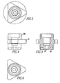
- Figs. 3 to 6 are drawings of the inner body defining a lower valve seat wherein Fig. 3 is a section view, Fig. 4 is a side view, Fig. 5 is a top view, and Fig. 6 is a bottom view;
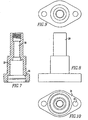
- Figs. 7 to 10 are drawings of the outer body defining the upper valve seat wherein Fig. 7 is a section view, Fig. 8 is a side view, Fig. 9 is a top view, and Fig. 10 is a bottom view;
- Figs. 11 to 14 are drawings of the plunger wherein Fig. 11 is a section view, Fig. 12 is a side view, Fig.13 is a top view, and Fig. 14 is a bottom view; and
- Figs. 15 is a top view of the plunger seal.
- the test point 10 has a spring biased plunger 12 with an entry port 14 and axial passage 16 therein.
- the test point comprises a body 20 defining a transfer chamber 22 having a fluid inlet port 24 and a fluid outlet port 26 and defining a plunger cylinder 28.
- the body is comprised of outer body 20A and inner body 20B joined together by snap ring 23.
- the outer body 20A has a hollow cylindrical shape having multiple interior diameters, one of which defines the plunger cylinder 28 and another which defines a transfer chamber 22. At the end of the transfer chamber, a recess 29 is provided for receipt of the inner body 20B. An annular groove 30 is provided for receipt of a sealing O-ring 33.
- the outer body at the enlarged end has a flange 31 with holes 32 for receiving fasteners for securing outer body to the portion of a pneumatic system to be tested.
- the inner body 20B has a hollow cylindrical shape.
- the interior hollow space defines the inlet port 24 to the test point.
- an annular groove is provided for receipt of a sealing O-ring 35.
- the inner body 20B has a radial flange 39 which extends outward with a surface for engaging and being restrained by a surface on the interior of the outer body 20A to restrict the axial movement into the recess 29 of the outer body 20A.
- a snap ring 23 on the other side of the flange captures the flange and, therefore, the inner body 20B in the outer body 20A.
- the flange 39 as shown Figs.
- the plunger 12 is slidably positioned in the plunger cylinder of the outer body 20A.
- the detailed configuration of the plunger 12 is shown in Figs. 11 to 14 .
- the plunger has an entry port 14 at an open axial end and an axial passage 16 extending at least partially through the plunger from the entry port 14.
- the plunger 12 has a radial passage 18 in communication with the axial passage 16 and with the exterior cylindrical surface of the plunger.
- valve stopper disc 40 The end of the plunger 12 near the radial passage 18 is seated in a valve stopper disc 40.
- the disc has two opposed axial face surfaces, both of which act with seats to stop flow as will be explained.
- the circumference of the valve stopper disc, as shown in Fig. 15 is configured to allow flow between the disc and the inner wall of the transfer chamber 22.
- the radial passage 18 in the plunger 12 opens into the transfer chamber 22. If the plunger is fully pressed, the bottom surface of the valve stopper disc 40 seats on the inner body 20B sealing the inlet port 24 and in which position the entry port 14 on the plunger is in communication only with the outlet port 26.
- the inlet port 24 is connected to a source of control pressure and the outlet port 26 is connected to the load control chamber of variable load relay valve used in pneumatic braking systems in rail vehicles.
- the plunger 12 has an intermediate position where the valve stopper disc is not seated and the radial passage 18 is in communication with the transfer chamber 22 and in which position the entry port of the plunger 12 is in communication with both the inlet port 24 and the outlet 26 port.
- fluid enters the base through inlet port 24 and flows into the transfer chamber 22 and outlet port 26.
- the plunger 12 is held by the sparing 36 into the plunger cylinder 28 preventing flow into the radial passage 18 and the axial passage 16 in the plunger 12.
- a controlled pressure For the purposes of calibration, a controlled pressure must be delivered to the device to be calibrated.
- the cover 42 (see Fig. 1 ) must be removed and replaced with a probe 44 (see Fig. 2 ). Probe 44 forces the plunger 12 to seat the stopper, thus sealing the inlet port 24. In this mode, controlled fluid can be injected into the outlet port 26 without affecting the portions of the pneumatic system upstream of the device.
- the probe 44 is not forced entirely down, leaving the stopper unseated. In this mode, the pressure at the input of the pneumatic device being tested can be observed during operation without disturbing flow.
- the high flow calibration test point described herein is designed to go between a fluid source and any device which requires calibration by injection of a controlled fluid pressure. Current devices provide this function, but they restrict flow through the test point. This restriction in flow can impact the operation on the device downstream from the test point.
- the high flow calibration test point provides a higher flow rate of fluid through the test point than current designs while maintaining leakage protection.
Landscapes
- Engineering & Computer Science (AREA)
- Physics & Mathematics (AREA)
- General Physics & Mathematics (AREA)
- Transportation (AREA)
- Mechanical Engineering (AREA)
- Examining Or Testing Airtightness (AREA)
- Lift Valve (AREA)
- Measuring Volume Flow (AREA)
- Testing Of Devices, Machine Parts, Or Other Structures Thereof (AREA)
- Fluid-Driven Valves (AREA)
- Analysing Materials By The Use Of Radiation (AREA)
- Multiple-Way Valves (AREA)
Abstract
Description
- This invention relates to a high flow calibration test point according to the preamble of claim 1 used for testing and calibrating pneumatic systems, such as the air brakes on a railway vehicle. In particular, this invention relates to a test point which is connected into the pneumatic system requiring testing and calibration.
- A test point according to the preamble of claim 1 is known from
DE 28 15 931 A1 - Generally speaking, test points are known for use with pneumatic and hydraulic systems. They enable temporary connection of expensive pressure sensors or meters into critical locations in the system for the analysis of problems within the system. When the testing is completed, the sensor can be removed for use elsewhere and the pneumatic system will be as secure as if it had no test point. The high flow test point to be described herein permits not only connection of sensors but calibration by the injection of controlled fluid pressure into an isolated portion of the system. The test point, according to this invention, has particular application with the variable load valves in the brake system of a railway transit vehicle.
- Briefly, according to this invention, a high flow calibration test point comprises a body defining a transfer chamber having a fluid inlet port and a fluid outlet port. Also within the body and connected to the transfer chamber is a plunger cylinder extending between the transfer chamber and the axial end of the body.
- A plunger is slidably positioned in the plunger cylinder. The plunger has an entry port at one axial end accessible from the outside of the body. An axial passage extends at least partially through the plunger from the entry port. The plunger has a radial passage in communication with the axial passage and with the exterior cylindrical surface of the plunger. In one position of the plunger, the radial passage is sealed from the transfer chamber and in another position it is in communication with the transfer chamber. A spring is positioned in the transfer chamber for biasing the plunger such that the entry port and radial passage in the plunger are sealed from the transfer chamber.
- The fluid inlet port of the transfer chamber is axially aligned with the plunger and defines a valve seat. The plunger has a valve stopper associated therewith. When the plunger is fully depressed against the spring, the stopper is seated and the radial passage in the plunger opens into the transfer chamber. In this position, the entry port in the plunger is in communication only with the outlet port of the transfer chamber. The plunger has an intermediate position where the valve stopper is not seated and the radial passage is still in communication with the transfer chamber. In this position, the entry port is in communication with both the inlet and outlet ports.
- Preferably, according to this invention, the body comprises an inner body and an outer body held together by a snap ring. The outer body defines the plunger cylinder and the inner body defines the inlet and outlet ports. The inner and outer bodies together define and enclose the transfer chamber.
- According to one embodiment, the plunger has an enlarged end for preventing the plunger from sliding completely through the plunger cylinder. The body comprised of inner and outer bodies enables the assembly of the plunger and spring into the transfer chamber.
- According to one embodiment, the plunger in the plunger cylinder does not extend entirely through the body. The portion of the plunger cylinder adjacent the exterior of the body is threaded to accept a threaded plug or probe.
- According to a preferred embodiment, a polymeric stopper disc engages the plunger and portions of the cylinder transfer chamber walls. The stopper disc has opposed faces, one of which seals the plunger cylinder from the transfer chamber and the other of which seals the inlet port from the transfer chamber depending upon the position of the plunger.
- Further features and other objects and advantages will become clear from the following detailed description made with reference to the drawings in which:
-
Fig. 1 is a cross section through a test point, according to this invention, in the stowed position; -
Fig. 2 is a cross section through a test point, according to this invention, in one of the testing positions; -
Figs. 3 to 6 are drawings of the inner body defining a lower valve seat whereinFig. 3 is a section view,Fig. 4 is a side view,Fig. 5 is a top view, andFig. 6 is a bottom view; -
Figs. 7 to 10 are drawings of the outer body defining the upper valve seat whereinFig. 7 is a section view,Fig. 8 is a side view,Fig. 9 is a top view, andFig. 10 is a bottom view; -
Figs. 11 to 14 are drawings of the plunger whereinFig. 11 is a section view,Fig. 12 is a side view,Fig.13 is a top view, andFig. 14 is a bottom view; and -
Figs. 15 is a top view of the plunger seal. - Referring to
Figs. 1 and 2 , the test point 10 has a springbiased plunger 12 with anentry port 14 andaxial passage 16 therein. The test point comprises abody 20 defining atransfer chamber 22 having afluid inlet port 24 and a fluid outlet port 26 and defining aplunger cylinder 28. The body is comprised ofouter body 20A andinner body 20B joined together by snap ring 23. - The detailed configuration of the
outer body 20A is illustrated inFigs. 7 to 10 . Theouter body 20A has a hollow cylindrical shape having multiple interior diameters, one of which defines theplunger cylinder 28 and another which defines atransfer chamber 22. At the end of the transfer chamber, arecess 29 is provided for receipt of theinner body 20B. Anannular groove 30 is provided for receipt of a sealing O-ring 33. The outer body at the enlarged end has aflange 31 withholes 32 for receiving fasteners for securing outer body to the portion of a pneumatic system to be tested. - The detailed configuration of the
inner body 20B is illustrated inFigs. 3 to 6 . The inner body has a hollow cylindrical shape. The interior hollow space defines theinlet port 24 to the test point. At one axial end, an annular groove is provided for receipt of a sealing O-ring 35. Theinner body 20B has aradial flange 39 which extends outward with a surface for engaging and being restrained by a surface on the interior of theouter body 20A to restrict the axial movement into therecess 29 of theouter body 20A. A snap ring 23 on the other side of the flange captures the flange and, therefore, theinner body 20B in theouter body 20A. Theflange 39, as shownFigs. 5 and 6 , has a triangular shape so that fluid can pass in the axial direction in the annular space between the exterior of the inner body and the interior of the outer body. This annular space defines an outlet port 26 for the test point. As can be seen fromFigs. 1 and 2 , the cylindrical portions of the inner and outer bodies have a common cylindrical axis. - The
plunger 12 is slidably positioned in the plunger cylinder of theouter body 20A. The detailed configuration of theplunger 12 is shown inFigs. 11 to 14 . The plunger has anentry port 14 at an open axial end and anaxial passage 16 extending at least partially through the plunger from theentry port 14. Theplunger 12 has aradial passage 18 in communication with theaxial passage 16 and with the exterior cylindrical surface of the plunger. - The end of the
plunger 12 near theradial passage 18 is seated in a valve stopper disc 40. The disc has two opposed axial face surfaces, both of which act with seats to stop flow as will be explained. The circumference of the valve stopper disc, as shown inFig. 15 , is configured to allow flow between the disc and the inner wall of thetransfer chamber 22. - A
spring 36 seated at one end in the inner body and at the other end in the valve stopper disc 40 biases the plunger and the valve stopper disc away frominner body 20B. In the position where thespring 36 is fully expanded the upper face of the valve stopper disc 40 seals onouter body 20A. - When the plunger is partially pressed against the stopper disc 40, the
radial passage 18 in theplunger 12 opens into thetransfer chamber 22. If the plunger is fully pressed, the bottom surface of the valve stopper disc 40 seats on theinner body 20B sealing theinlet port 24 and in which position theentry port 14 on the plunger is in communication only with the outlet port 26. - In one application of the high flow test point, the
inlet port 24 is connected to a source of control pressure and the outlet port 26 is connected to the load control chamber of variable load relay valve used in pneumatic braking systems in rail vehicles. - The
plunger 12 has an intermediate position where the valve stopper disc is not seated and theradial passage 18 is in communication with thetransfer chamber 22 and in which position the entry port of theplunger 12 is in communication with both theinlet port 24 and the outlet 26 port. - In the mode where no testing or calibration is taking place, fluid enters the base through
inlet port 24 and flows into thetransfer chamber 22 and outlet port 26. Theplunger 12 is held by the sparing 36 into theplunger cylinder 28 preventing flow into theradial passage 18 and theaxial passage 16 in theplunger 12. - For the purposes of calibration, a controlled pressure must be delivered to the device to be calibrated. The cover 42 (see
Fig. 1 ) must be removed and replaced with a probe 44 (seeFig. 2 ). Probe 44 forces theplunger 12 to seat the stopper, thus sealing theinlet port 24. In this mode, controlled fluid can be injected into the outlet port 26 without affecting the portions of the pneumatic system upstream of the device. - For purposes of monitoring the pneumatic system, the probe 44 is not forced entirely down, leaving the stopper unseated. In this mode, the pressure at the input of the pneumatic device being tested can be observed during operation without disturbing flow.
- The high flow calibration test point described herein is designed to go between a fluid source and any device which requires calibration by injection of a controlled fluid pressure. Current devices provide this function, but they restrict flow through the test point. This restriction in flow can impact the operation on the device downstream from the test point. The high flow calibration test point provides a higher flow rate of fluid through the test point than current designs while maintaining leakage protection.
- Having thus described the invention in the detail and particularity required by the Patent Laws, what is desired protected by Letters Patent is set forth in the following claims.
Claims (5)
- A high flow calibration test point comprising:a body (10) defining a transfer chamber (22) having a fluid inlet port (24) and a fluid outlet port (26) and defining a plunger cylinder (28) in communication with the transfer chamber and test point port;a plunger (12) slidably positioned in the plunger cylinder (28), said plunger having an entry port (14) at an open axial end, and an axial passage (16) extending at least partially through the plunger from the entry port, said plunger having a radial passage (18) in communication with the exterior cylindrical surface of the plunger;a spring (36) in the transfer chamber for biasing the plunger away from the transfer chamber (22) such that the radial passages (18) in the plunger (12) are blocked from the transfer chamber;said fluid inlet port (24) being axially aligned with the plunger and defining a valve seat;said plunger (12) having a valve stopper (40) at one end thereof for being seated in said valve seat at the inlet port when the plunger is depressed against the spring and the radial passage in the plunger opens into the transfer chamber in which position the entry port in the plunger is in communication only with the outlet port of the transfer chamber;characterized in that said plunger has an intermediate position where the valve stopper (40) is not seated and the radial passage is in communication with the transfer chamber in which position the entry port (14) in the plunger is in communication with both the inlet and outlet ports of the transfer chamber (22).
- The test point according to claim 1, wherein the body (10) comprises inner and outer bodies, the outer body defining the plunger cylinder (28) and the inner body defining the inlet and outlet ports of the transfer chamber (22) and the inner and outer bodies together defining the transfer chamber.
- The test point according to claim 2, wherein the plunger (12) has an enlarged end for securing one end of the spring and for preventing the plunger from sliding too far out of the transfer chamber.
- The test point according to claim 1, wherein the inner body is positioned axially aligned within the outer body and is held in place by a snap ring (23).
- The test point according to claim 1, where a polymeric stopper seal (40) engages the plunger (12) and portions of the cylinder transfer chamber walls, said stopper having opposed faces, one of which is positionable to seal the plunger cylinder from the transfer chamber and the other of which is positionable to seal the inlet port from the transfer chamber depending upon the position of the plunger.
Applications Claiming Priority (2)
| Application Number | Priority Date | Filing Date | Title |
|---|---|---|---|
| US11/486,560 US7543796B2 (en) | 2006-07-14 | 2006-07-14 | High flow calibration test point |
| PCT/US2007/072741 WO2008008668A2 (en) | 2006-07-14 | 2007-07-03 | High flow calibration test point |
Publications (2)
| Publication Number | Publication Date |
|---|---|
| EP2040968A2 EP2040968A2 (en) | 2009-04-01 |
| EP2040968B1 true EP2040968B1 (en) | 2011-10-19 |
Family
ID=38924035
Family Applications (1)
| Application Number | Title | Priority Date | Filing Date |
|---|---|---|---|
| EP20070799276 Not-in-force EP2040968B1 (en) | 2006-07-14 | 2007-07-03 | High flow calibration test point |
Country Status (11)
| Country | Link |
|---|---|
| US (1) | US7543796B2 (en) |
| EP (1) | EP2040968B1 (en) |
| JP (1) | JP4909411B2 (en) |
| CN (1) | CN101489846B (en) |
| AT (1) | ATE529311T1 (en) |
| AU (1) | AU2007272651B2 (en) |
| CA (1) | CA2647828C (en) |
| MX (1) | MX2008012838A (en) |
| TW (1) | TWI393647B (en) |
| WO (1) | WO2008008668A2 (en) |
| ZA (1) | ZA200808228B (en) |
Families Citing this family (2)
| Publication number | Priority date | Publication date | Assignee | Title |
|---|---|---|---|---|
| FR2940431B1 (en) * | 2008-12-22 | 2012-08-03 | Schneider Electric Ind Sas | DEVICE FOR MEASURING A SIZE SUCH AS PRESSURE WITHIN A TANK FILLED WITH GAS OR LIQUID |
| EA019526B1 (en) * | 2010-09-20 | 2014-04-30 | Кнорр-Бремзе Зюстеме Фюр Шиненфарцойге Гмбх | Pneumatic control valve with regulated compressed air feed to a brake cylinder |
Family Cites Families (21)
| Publication number | Priority date | Publication date | Assignee | Title |
|---|---|---|---|---|
| US1451644A (en) | 1919-09-30 | 1923-04-10 | Charles E Zachary | Air-brake test valve |
| US2316217A (en) | 1941-02-03 | 1943-04-13 | Birch Thomas Henry | Single car testing device |
| US2993199A (en) | 1950-12-29 | 1961-07-18 | Chesapeake & Ohio Railway | Train inspection apparatus |
| US3049148A (en) * | 1962-03-20 | 1962-08-14 | John R Richardson | Calibration valve |
| US3304420A (en) | 1964-09-29 | 1967-02-14 | George S Bowman | Apparatus for checking integrity of brake pipe of fluid pressure brake system and preconditioning brake system for automated control |
| US3531981A (en) | 1968-12-27 | 1970-10-06 | Westinghouse Air Brake Co | Test apparatus to detect restriction in the brake pipe of railway brake systems |
| US3596500A (en) | 1969-05-05 | 1971-08-03 | Rees J G | Apparatus for testing airbrake control valves |
| DE2036161A1 (en) | 1970-07-21 | 1972-01-27 | Graubremse Gmbh, 6900 Heidelberg | Automatic load-dependent brake valve for vehicles with compressed air brakes with air suspension |
| US3817282A (en) * | 1972-09-14 | 1974-06-18 | C Peters | In-line test valve |
| US3799107A (en) | 1973-06-11 | 1974-03-26 | O Sumner | Positive fluid flow indicator |
| US4050298A (en) | 1975-05-08 | 1977-09-27 | Hope Technical Developments Limited | Manually operated control valve and testing apparatus incorporating such valve |
| US3987817A (en) * | 1975-12-24 | 1976-10-26 | Acf Industries, Incorporated | Test valve for fluid actuated pilot valve |
| DE2815931A1 (en) | 1978-04-13 | 1979-10-18 | Voss Armaturen | Test connection for regulated brakes - has sprung connector and cover for manometer connection |
| DE3001679C2 (en) | 1980-01-18 | 1984-07-19 | Wabco Westinghouse Fahrzeugbremsen GmbH, 3000 Hannover | Load-dependent brake force regulator |
| US4510970A (en) * | 1983-01-10 | 1985-04-16 | Joy Manufacturing Company | Dual seal in-line test valve |
| CN2058105U (en) * | 1989-08-01 | 1990-06-13 | 虞忠保 | Connecting unit of pressure measuring instrument |
| US5606988A (en) * | 1994-02-04 | 1997-03-04 | Hewlett -Packard Company | Connector assembly for ink cartridge |
| US5668314A (en) | 1996-07-19 | 1997-09-16 | Jones; Robert | Apparatus for testing vehicle air brakes |
| FR2858374B1 (en) * | 2003-07-29 | 2007-10-26 | Delphi Tech Inc | ELECTROVALVE, METHOD FOR ASSEMBLING A SOLENOID ON SAID ELECTROVALVE, AND METHOD FOR DISASSEMBLING SOLENOID OF SAID ELECTROVALVE |
| CN2776778Y (en) * | 2004-07-06 | 2006-05-03 | 四川制动科技股份有限公司 | Stepless automatic pressure regulating device for brake cylinder of empty and heavy railway vehicle |
| US20070215219A1 (en) * | 2006-03-17 | 2007-09-20 | Wabtec Holding Corporation | Variable load valve with test point |
-
2006
- 2006-07-14 US US11/486,560 patent/US7543796B2/en active Active
-
2007
- 2007-07-03 AU AU2007272651A patent/AU2007272651B2/en not_active Ceased
- 2007-07-03 WO PCT/US2007/072741 patent/WO2008008668A2/en not_active Ceased
- 2007-07-03 EP EP20070799276 patent/EP2040968B1/en not_active Not-in-force
- 2007-07-03 CA CA 2647828 patent/CA2647828C/en not_active Expired - Fee Related
- 2007-07-03 CN CN2007800258149A patent/CN101489846B/en not_active Expired - Fee Related
- 2007-07-03 JP JP2009519591A patent/JP4909411B2/en not_active Expired - Fee Related
- 2007-07-03 MX MX2008012838A patent/MX2008012838A/en active IP Right Grant
- 2007-07-03 AT AT07799276T patent/ATE529311T1/en not_active IP Right Cessation
- 2007-07-10 TW TW96125034A patent/TWI393647B/en not_active IP Right Cessation
-
2008
- 2008-09-26 ZA ZA200808228A patent/ZA200808228B/en unknown
Also Published As
| Publication number | Publication date |
|---|---|
| JP4909411B2 (en) | 2012-04-04 |
| CN101489846B (en) | 2011-11-16 |
| WO2008008668A3 (en) | 2008-05-08 |
| ZA200808228B (en) | 2009-11-25 |
| AU2007272651B2 (en) | 2011-11-10 |
| CN101489846A (en) | 2009-07-22 |
| JP2009543984A (en) | 2009-12-10 |
| TWI393647B (en) | 2013-04-21 |
| US7543796B2 (en) | 2009-06-09 |
| AU2007272651A1 (en) | 2008-01-17 |
| MX2008012838A (en) | 2008-10-17 |
| ATE529311T1 (en) | 2011-11-15 |
| CA2647828C (en) | 2013-06-11 |
| CA2647828A1 (en) | 2008-01-17 |
| TW200812854A (en) | 2008-03-16 |
| EP2040968A2 (en) | 2009-04-01 |
| WO2008008668A2 (en) | 2008-01-17 |
| US20080121291A1 (en) | 2008-05-29 |
Similar Documents
| Publication | Publication Date | Title |
|---|---|---|
| US10955091B2 (en) | Tank valve | |
| US8770361B2 (en) | Residual pressure holding valve and suspension strut | |
| US8967182B2 (en) | Tire valve | |
| US9637100B2 (en) | Hydraulic unit for a slip control system of a hydraulic vehicle brake system | |
| US5451099A (en) | Railway brake pipe bracket access plate | |
| EP3205915B1 (en) | Pilot check valve | |
| US20060060806A1 (en) | Fluid controller | |
| AU2007272651B2 (en) | High flow calibration test point | |
| US20040256005A1 (en) | Relief valve | |
| US7555902B2 (en) | Tandem master cylinder with central valves | |
| JP4963508B2 (en) | Variable load control valve with test tip | |
| US6213566B1 (en) | Brake proportioning in-line ball valve | |
| US12044330B2 (en) | Valve and device for controlling pressures of a flow medium | |
| US20050034772A1 (en) | Relay valve | |
| US444782A (en) | Thomas w | |
| AU742633B2 (en) | Remote brake application valve | |
| AU707561B2 (en) | Railway brake pipe bracket with access ports | |
| EP1533551A1 (en) | Excess flow valve |
Legal Events
| Date | Code | Title | Description |
|---|---|---|---|
| PUAI | Public reference made under article 153(3) epc to a published international application that has entered the european phase |
Free format text: ORIGINAL CODE: 0009012 |
|
| 17P | Request for examination filed |
Effective date: 20080930 |
|
| AK | Designated contracting states |
Kind code of ref document: A2 Designated state(s): AT BE BG CH CY CZ DE DK EE ES FI FR GB GR HU IE IS IT LI LT LU LV MC MT NL PL PT RO SE SI SK TR |
|
| DAX | Request for extension of the european patent (deleted) | ||
| R17D | Deferred search report published (corrected) |
Effective date: 20080508 |
|
| GRAP | Despatch of communication of intention to grant a patent |
Free format text: ORIGINAL CODE: EPIDOSNIGR1 |
|
| GRAS | Grant fee paid |
Free format text: ORIGINAL CODE: EPIDOSNIGR3 |
|
| GRAA | (expected) grant |
Free format text: ORIGINAL CODE: 0009210 |
|
| AK | Designated contracting states |
Kind code of ref document: B1 Designated state(s): AT BE BG CH CY CZ DE DK EE ES FI FR GB GR HU IE IS IT LI LT LU LV MC MT NL PL PT RO SE SI SK TR |
|
| REG | Reference to a national code |
Ref country code: GB Ref legal event code: FG4D |
|
| REG | Reference to a national code |
Ref country code: CH Ref legal event code: EP |
|
| REG | Reference to a national code |
Ref country code: IE Ref legal event code: FG4D |
|
| REG | Reference to a national code |
Ref country code: DE Ref legal event code: R096 Ref document number: 602007018094 Country of ref document: DE Effective date: 20111222 |
|
| REG | Reference to a national code |
Ref country code: NL Ref legal event code: VDEP Effective date: 20111019 |
|
| LTIE | Lt: invalidation of european patent or patent extension |
Effective date: 20111019 |
|
| REG | Reference to a national code |
Ref country code: AT Ref legal event code: MK05 Ref document number: 529311 Country of ref document: AT Kind code of ref document: T Effective date: 20111019 |
|
| PG25 | Lapsed in a contracting state [announced via postgrant information from national office to epo] |
Ref country code: IS Free format text: LAPSE BECAUSE OF FAILURE TO SUBMIT A TRANSLATION OF THE DESCRIPTION OR TO PAY THE FEE WITHIN THE PRESCRIBED TIME-LIMIT Effective date: 20120219 Ref country code: BE Free format text: LAPSE BECAUSE OF FAILURE TO SUBMIT A TRANSLATION OF THE DESCRIPTION OR TO PAY THE FEE WITHIN THE PRESCRIBED TIME-LIMIT Effective date: 20111019 Ref country code: LT Free format text: LAPSE BECAUSE OF FAILURE TO SUBMIT A TRANSLATION OF THE DESCRIPTION OR TO PAY THE FEE WITHIN THE PRESCRIBED TIME-LIMIT Effective date: 20111019 |
|
| PG25 | Lapsed in a contracting state [announced via postgrant information from national office to epo] |
Ref country code: PT Free format text: LAPSE BECAUSE OF FAILURE TO SUBMIT A TRANSLATION OF THE DESCRIPTION OR TO PAY THE FEE WITHIN THE PRESCRIBED TIME-LIMIT Effective date: 20120220 Ref country code: LV Free format text: LAPSE BECAUSE OF FAILURE TO SUBMIT A TRANSLATION OF THE DESCRIPTION OR TO PAY THE FEE WITHIN THE PRESCRIBED TIME-LIMIT Effective date: 20111019 Ref country code: GR Free format text: LAPSE BECAUSE OF FAILURE TO SUBMIT A TRANSLATION OF THE DESCRIPTION OR TO PAY THE FEE WITHIN THE PRESCRIBED TIME-LIMIT Effective date: 20120120 Ref country code: NL Free format text: LAPSE BECAUSE OF FAILURE TO SUBMIT A TRANSLATION OF THE DESCRIPTION OR TO PAY THE FEE WITHIN THE PRESCRIBED TIME-LIMIT Effective date: 20111019 Ref country code: SI Free format text: LAPSE BECAUSE OF FAILURE TO SUBMIT A TRANSLATION OF THE DESCRIPTION OR TO PAY THE FEE WITHIN THE PRESCRIBED TIME-LIMIT Effective date: 20111019 Ref country code: SE Free format text: LAPSE BECAUSE OF FAILURE TO SUBMIT A TRANSLATION OF THE DESCRIPTION OR TO PAY THE FEE WITHIN THE PRESCRIBED TIME-LIMIT Effective date: 20111019 |
|
| PG25 | Lapsed in a contracting state [announced via postgrant information from national office to epo] |
Ref country code: CY Free format text: LAPSE BECAUSE OF FAILURE TO SUBMIT A TRANSLATION OF THE DESCRIPTION OR TO PAY THE FEE WITHIN THE PRESCRIBED TIME-LIMIT Effective date: 20111019 |
|
| PG25 | Lapsed in a contracting state [announced via postgrant information from national office to epo] |
Ref country code: DK Free format text: LAPSE BECAUSE OF FAILURE TO SUBMIT A TRANSLATION OF THE DESCRIPTION OR TO PAY THE FEE WITHIN THE PRESCRIBED TIME-LIMIT Effective date: 20111019 Ref country code: EE Free format text: LAPSE BECAUSE OF FAILURE TO SUBMIT A TRANSLATION OF THE DESCRIPTION OR TO PAY THE FEE WITHIN THE PRESCRIBED TIME-LIMIT Effective date: 20111019 Ref country code: BG Free format text: LAPSE BECAUSE OF FAILURE TO SUBMIT A TRANSLATION OF THE DESCRIPTION OR TO PAY THE FEE WITHIN THE PRESCRIBED TIME-LIMIT Effective date: 20120119 Ref country code: SK Free format text: LAPSE BECAUSE OF FAILURE TO SUBMIT A TRANSLATION OF THE DESCRIPTION OR TO PAY THE FEE WITHIN THE PRESCRIBED TIME-LIMIT Effective date: 20111019 Ref country code: CZ Free format text: LAPSE BECAUSE OF FAILURE TO SUBMIT A TRANSLATION OF THE DESCRIPTION OR TO PAY THE FEE WITHIN THE PRESCRIBED TIME-LIMIT Effective date: 20111019 |
|
| PLBE | No opposition filed within time limit |
Free format text: ORIGINAL CODE: 0009261 |
|
| STAA | Information on the status of an ep patent application or granted ep patent |
Free format text: STATUS: NO OPPOSITION FILED WITHIN TIME LIMIT |
|
| PG25 | Lapsed in a contracting state [announced via postgrant information from national office to epo] |
Ref country code: PL Free format text: LAPSE BECAUSE OF FAILURE TO SUBMIT A TRANSLATION OF THE DESCRIPTION OR TO PAY THE FEE WITHIN THE PRESCRIBED TIME-LIMIT Effective date: 20111019 Ref country code: RO Free format text: LAPSE BECAUSE OF FAILURE TO SUBMIT A TRANSLATION OF THE DESCRIPTION OR TO PAY THE FEE WITHIN THE PRESCRIBED TIME-LIMIT Effective date: 20111019 |
|
| 26N | No opposition filed |
Effective date: 20120720 |
|
| REG | Reference to a national code |
Ref country code: DE Ref legal event code: R097 Ref document number: 602007018094 Country of ref document: DE Effective date: 20120720 |
|
| PG25 | Lapsed in a contracting state [announced via postgrant information from national office to epo] |
Ref country code: AT Free format text: LAPSE BECAUSE OF FAILURE TO SUBMIT A TRANSLATION OF THE DESCRIPTION OR TO PAY THE FEE WITHIN THE PRESCRIBED TIME-LIMIT Effective date: 20111019 |
|
| PG25 | Lapsed in a contracting state [announced via postgrant information from national office to epo] |
Ref country code: MC Free format text: LAPSE BECAUSE OF NON-PAYMENT OF DUE FEES Effective date: 20120731 |
|
| REG | Reference to a national code |
Ref country code: CH Ref legal event code: PL |
|
| PG25 | Lapsed in a contracting state [announced via postgrant information from national office to epo] |
Ref country code: CH Free format text: LAPSE BECAUSE OF NON-PAYMENT OF DUE FEES Effective date: 20120731 Ref country code: LI Free format text: LAPSE BECAUSE OF NON-PAYMENT OF DUE FEES Effective date: 20120731 Ref country code: ES Free format text: LAPSE BECAUSE OF FAILURE TO SUBMIT A TRANSLATION OF THE DESCRIPTION OR TO PAY THE FEE WITHIN THE PRESCRIBED TIME-LIMIT Effective date: 20120130 |
|
| REG | Reference to a national code |
Ref country code: IE Ref legal event code: MM4A |
|
| PG25 | Lapsed in a contracting state [announced via postgrant information from national office to epo] |
Ref country code: FI Free format text: LAPSE BECAUSE OF FAILURE TO SUBMIT A TRANSLATION OF THE DESCRIPTION OR TO PAY THE FEE WITHIN THE PRESCRIBED TIME-LIMIT Effective date: 20111019 |
|
| PG25 | Lapsed in a contracting state [announced via postgrant information from national office to epo] |
Ref country code: MT Free format text: LAPSE BECAUSE OF FAILURE TO SUBMIT A TRANSLATION OF THE DESCRIPTION OR TO PAY THE FEE WITHIN THE PRESCRIBED TIME-LIMIT Effective date: 20111019 Ref country code: IE Free format text: LAPSE BECAUSE OF NON-PAYMENT OF DUE FEES Effective date: 20120703 |
|
| PG25 | Lapsed in a contracting state [announced via postgrant information from national office to epo] |
Ref country code: TR Free format text: LAPSE BECAUSE OF FAILURE TO SUBMIT A TRANSLATION OF THE DESCRIPTION OR TO PAY THE FEE WITHIN THE PRESCRIBED TIME-LIMIT Effective date: 20111019 |
|
| PG25 | Lapsed in a contracting state [announced via postgrant information from national office to epo] |
Ref country code: LU Free format text: LAPSE BECAUSE OF NON-PAYMENT OF DUE FEES Effective date: 20120703 |
|
| PG25 | Lapsed in a contracting state [announced via postgrant information from national office to epo] |
Ref country code: HU Free format text: LAPSE BECAUSE OF FAILURE TO SUBMIT A TRANSLATION OF THE DESCRIPTION OR TO PAY THE FEE WITHIN THE PRESCRIBED TIME-LIMIT Effective date: 20070703 |
|
| REG | Reference to a national code |
Ref country code: FR Ref legal event code: PLFP Year of fee payment: 9 |
|
| PGFP | Annual fee paid to national office [announced via postgrant information from national office to epo] |
Ref country code: DE Payment date: 20150630 Year of fee payment: 9 Ref country code: GB Payment date: 20150701 Year of fee payment: 9 |
|
| PGFP | Annual fee paid to national office [announced via postgrant information from national office to epo] |
Ref country code: FR Payment date: 20150629 Year of fee payment: 9 |
|
| PGFP | Annual fee paid to national office [announced via postgrant information from national office to epo] |
Ref country code: IT Payment date: 20150727 Year of fee payment: 9 |
|
| REG | Reference to a national code |
Ref country code: DE Ref legal event code: R119 Ref document number: 602007018094 Country of ref document: DE |
|
| GBPC | Gb: european patent ceased through non-payment of renewal fee |
Effective date: 20160703 |
|
| PG25 | Lapsed in a contracting state [announced via postgrant information from national office to epo] |
Ref country code: FR Free format text: LAPSE BECAUSE OF NON-PAYMENT OF DUE FEES Effective date: 20160801 Ref country code: DE Free format text: LAPSE BECAUSE OF NON-PAYMENT OF DUE FEES Effective date: 20170201 |
|
| REG | Reference to a national code |
Ref country code: FR Ref legal event code: ST Effective date: 20170331 |
|
| PG25 | Lapsed in a contracting state [announced via postgrant information from national office to epo] |
Ref country code: GB Free format text: LAPSE BECAUSE OF NON-PAYMENT OF DUE FEES Effective date: 20160703 |
|
| PG25 | Lapsed in a contracting state [announced via postgrant information from national office to epo] |
Ref country code: IT Free format text: LAPSE BECAUSE OF NON-PAYMENT OF DUE FEES Effective date: 20160703 |