EP2040442A1 - Portable device having a semi-automatic sliding cover mechanism - Google Patents
Portable device having a semi-automatic sliding cover mechanism Download PDFInfo
- Publication number
- EP2040442A1 EP2040442A1 EP08162272A EP08162272A EP2040442A1 EP 2040442 A1 EP2040442 A1 EP 2040442A1 EP 08162272 A EP08162272 A EP 08162272A EP 08162272 A EP08162272 A EP 08162272A EP 2040442 A1 EP2040442 A1 EP 2040442A1
- Authority
- EP
- European Patent Office
- Prior art keywords
- arc
- sliding
- sliding member
- sliding track
- roller set
- Prior art date
- Legal status (The legal status is an assumption and is not a legal conclusion. Google has not performed a legal analysis and makes no representation as to the accuracy of the status listed.)
- Withdrawn
Links
- 238000005381 potential energy Methods 0.000 claims abstract description 17
- 230000003247 decreasing effect Effects 0.000 description 4
- 238000010586 diagram Methods 0.000 description 3
- 238000011084 recovery Methods 0.000 description 3
- 230000000712 assembly Effects 0.000 description 2
- 238000000429 assembly Methods 0.000 description 2
- 238000005516 engineering process Methods 0.000 description 2
- 238000012986 modification Methods 0.000 description 2
- 230000004048 modification Effects 0.000 description 2
- 238000004891 communication Methods 0.000 description 1
- 238000004519 manufacturing process Methods 0.000 description 1
- 230000000750 progressive effect Effects 0.000 description 1
Images




Classifications
-
- H—ELECTRICITY
- H04—ELECTRIC COMMUNICATION TECHNIQUE
- H04M—TELEPHONIC COMMUNICATION
- H04M1/00—Substation equipment, e.g. for use by subscribers
- H04M1/02—Constructional features of telephone sets
- H04M1/0202—Portable telephone sets, e.g. cordless phones, mobile phones or bar type handsets
- H04M1/0206—Portable telephones comprising a plurality of mechanically joined movable body parts, e.g. hinged housings
- H04M1/0208—Portable telephones comprising a plurality of mechanically joined movable body parts, e.g. hinged housings characterized by the relative motions of the body parts
- H04M1/0235—Slidable or telescopic telephones, i.e. with a relative translation movement of the body parts; Telephones using a combination of translation and other relative motions of the body parts
- H04M1/0237—Sliding mechanism with one degree of freedom
Definitions
- the invention relates to an electronic device and a sliding cover structure thereof.
- a conventional mobile phone 1 includes an upper housing 11 and a lower housing 12, which are connected by a hinge (not shown).
- a display area 111 which exposes a display panel, is disposed on the top surface S of the upper housing 11.
- the lower housing 12 has a bottom area 121.
- the mobile phone 1 can be opened to expose the bottom area 121 for operation.
- the user can dial the bottom area 121 to make a phone call or operate the bottom area 121 according to the information displayed on the display area 111.
- An object of the invention is to provide an electronic device with a sliding cover structure, which can be opened or closed semi-automatically.
- the invention discloses a sliding cover structure including a first sliding member, a second sliding member and a first roller assembly.
- the first sliding member has a first arc sliding track.
- the second sliding member is disposed opposite to the first sliding member.
- the first roller assembly includes a first elastic element and a first roller set. At least one end of the first elastic element is fixed to the second sliding member, and the first roller set is fixed to the first elastic element and slides along the first arc sliding track.
- the first sliding member is forced to slide relatively to the second sliding member, the first roller set slides along the first arc sliding track and the first elastic element deforms to accumulate an elastic potential energy. After the first roller set passes the top of the first arc sliding track, the elastic potential energy is released to make the first sliding member slide along the first arc sliding track automatically.
- the invention also discloses an electronic device including a first housing, a second housing and a first roller assembly.
- the first housing includes a first sliding member, which has a first arc sliding track.
- the second housing is slidingly connected to the first housing and includes a second sliding member.
- the first roller assembly includes a first elastic element and a first roller set. At least one end of the first elastic element is fixed to the second sliding member, and the first roller set is fixed to the first elastic element and slides along the first arc sliding track.
- the first housing is forced so the first sliding member is slid relatively to the second sliding member, the first roller set slides along the first arc sliding track and the first elastic element deforms to accumulate an elastic potential energy. After the first roller set passes the top of the first arc sliding track, the elastic potential energy is released to make the first sliding member slide along the first arc sliding track automatically.
- the electronic device and sliding cover structure thereof of the invention utilize the cooperation of the arc sliding track of the first sliding member and the roller set of the second sliding member, so that the roller set, which is fixed on the elastic element, can slide on the arc sliding track so as to generate the relative movement of the first and second sliding members.
- the bottom area can be covered and protected by the first sliding member.
- the first and second sliding members can relatively move to expose the bottom area.
- the user can operate the bottom area.
- the first arc sliding track has an arc shape
- the semi-automatic sliding function can be performed according to the relative movement of the first and second sliding members. This can increase the convenience of the user.
- the connection interface of the first and second sliding members can be efficiently minimized by the combination usage of the first arc sliding track and the first roller set, thereby decreasing the thickness of the electronic device.
- FIG. 1 is a schematic diagram showing a conventional mobile phone
- FIG. 2 is a schematic diagram of an electronic device according to a first preferred embodiment of the invention.
- FIG. 3A is a top view of a first sliding member and a second sliding member of the electronic device of FIG. 2 ;
- FIG. 3B is an enlarged sectional view of the first sliding member and the second sliding member along the line AA of FIG. 3A ;
- FIGS. 4A to 4C are top views showing the movement of the first sliding member and the second sliding member of the electronic device of FIG. 2 ;
- FIG. 5A is a top view of an electronic device according to a second preferred embodiment of the invention.
- FIG. 5B is an enlarged sectional view of a first sliding member and a second sliding member along the line BB of FIG. 5A ;
- FIG. 6A is a top view of an electronic device according to a third preferred embodiment of the invention.
- FIG. 6B is an enlarged sectional view of a first sliding member and a second sliding member along the line CC of FIG. 6A ;
- FIG. 7A is a top view of an electronic device according to a fourth preferred embodiment of the invention.
- FIG. 7B is an enlarged sectional view of a first sliding member and a second sliding member along the line DD of FIG. 7A .
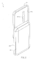
- FIG. 2 is a schematic diagram of an electronic device 2 according to a first preferred embodiment of the invention.
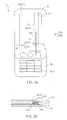
- FIG. 3A is a top view of a first sliding member 211 and a second sliding member 221 of the electronic device 2 of FIG. 2 .
- FIG. 3B is an enlarged sectional view of the first sliding member 211 and the second sliding member 221 along the line AA of FIG. 3A .
- the electronic device 2 includes a first housing 21, a second housing 22 and a first sliding assembly 23.
- the electronic device 2 is, for example, a mobile phone.
- the electronic device 2 can be any electronic device with a sliding cover structure such as a PDA (personal digital assistant), a mini computer or a digital media player.
- PDA personal digital assistant
- the first housing 21 has a first sliding member 211 and an opening 212.
- the first sliding member 211 has a first arc sliding track 211a disposed opposite to the second sliding member 221.
- the first sliding member 211 is, for example, a circular arc and has a first recess C1 and a second recess C2.
- a display panel 24 is disposed in the opening 212 and is accommodated between the first sliding member 211 and the first housing 21.
- the second housing 22 is slidingly connected to the first housing 21 and has a second sliding member 221 disposed opposite to the first sliding member 211.
- the second sliding member 221 has a bottom area 221a, and the user can dial the bottoms in the bottom area 221a to make a phone call or send a message.
- the first roller assembly 23 includes a first roller set 231 and a first elastic element 232.
- the first elastic element 232 can be a spring or a wire spring.
- the first elastic element 232 is disposed adjacent to the first arc sliding track 211a, and the extension direction of the first elastic element 232 is the track direction of the first arc sliding track 211a.
- the first elastic element 232 is a wire spring.
- At least one end of the first elastic element 232 is fixed to the second sliding member 221.
- two ends of the first elastic element 232 are fixed to the second sliding member 221, for example.
- the first roller set 231 has a first fixing portion 2311 and a first roller 2312.
- the center of the first roller 2312 and the center of the first arc sliding track 211a which is a circular arc, are disposed at different sides of the first arc sliding track 211a.
- the first fixing portion 2311 is fixed on the first elastic element 232.
- the first roller 2312 is slidingly disposed on the first arc sliding track 211a, and is capable of sliding between the first recess C1 and the second recess C2.
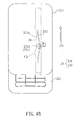
- FIGS. 4A to 4C are top views showing the movement of the first sliding member 211 relative to the second sliding member 221 of the electronic device 2 of FIG. 2 .
- the movements of the first housing 21 and the second housing 22 are depending on the first sliding member 211 and the second sliding member 221, respectively, so the following illustrations will focus on the first sliding member 211 and the second sliding member 221 only.
- the electronic device 2 is initially closed. That is, the first sliding member 211 completely covers the bottom area of the second sliding member (not shown).
- a user wants to use the bottom area, he or she must apply a force on the first sliding member 211 along a first direction D1 (opening direction).
- the first roller 2312 which is disposed on the second sliding member 221, can be slid out of the first recess C1 of the first arc sliding track 211a.
- the first sliding member 211 is moved toward the first direction D1.
- the first roller assembly 23 is fixed, and the first sliding member 211 is moved relative to the second sliding member and the first roller assembly 23.
- the first elastic element 232 of the first roller assembly 23 deforms to accumulate an elastic potential energy.
- a recovery force F1 which is perpendicular to the first direction D1 is applied to the first roller set 231, so that the first roller 2312 can be close to the first arc sliding track 211a and slide along the first arc sliding track 211a.
- the user continuously applies the force to the first sliding member 211.
- the slope of the first arc sliding track 211a is transformed from upwards to downwards.
- the first elastic element 232 can release its elastic potential energy to make the first roller 2312 slide along the first arc sliding track 211a automatically.
- the user does not have to apply force continuously, and the roller 2312 can automatically slide to the second recess C2.
- the first sliding member 211 can be moved to an opening position and then fixed.
- the bottom area 221a of the second sliding member 221 can be exposed for the user to use it.
- the first roller 2312 which is disposed on the second sliding member 221, can be slid out of the second recess C2 of the first arc sliding track 211a, and move toward the second direction D2.
- the first roller 2312 can move toward the second direction D2 and be fixed at the first recess C1 according to the above-mentioned manner.
- the first sliding member 211 can completely cover the bottom area 221a of the second sliding member 221, so that the electronic device 2 returns to the closing status as shown in FIG. 4A .
- the first sliding member 211 and the second sliding member 221 can have relative movement according to the cooperation of the first arc sliding track 211a and the first roller set 231.
- the bottom area 221a can be covered by the first sliding member 211.
- the bottom area 221a can be exposed for operations by pushing the first sliding member 211 to generate the relative movement of the first sliding member 211 and the second sliding member 221.
- the first arc sliding track 211a has an arc shape, the semi-automatic sliding function can be performed according to the relative movement of the first sliding member 211 and the second sliding member 221.
- connection interface of the first sliding member 211 and the second sliding member 221 can be efficiently minimized by the combination usage of the first arc sliding track 211a and the first roller set 231, thereby decreasing the thickness of the electronic device 2.
- FIG. 5A is a top view of an electronic device 3.
- FIG. 5B is an enlarged sectional view of the first sliding member 311 and the second sliding member 321 along the line BB of FIG. 5A .
- the difference between the electronic device 3 and the electronic device 2 of the first embodiment is in that only one end of the first elastic element 332 is fixed to the second sliding member 321.
- the first roller set 331 can slide along the first arc sliding track 311a.
- the first elastic element 332 deforms to accumulate an elastic potential energy, thereby make the first roller set 331 close to the first arc sliding track 311a.
- the length of the first elastic element 332 can be shortened.
- the manufacturing efficiency of the electronic device 3 can be increased, and the cost thereof can be decreased.
- FIG. 6A is a top view of an electronic device 4.
- FIG. 6B is an enlarged sectional view of the first sliding member 411 and the second sliding member 421 along the line CC of FIG. 6A .
- the difference between the electronic device 4 and the electronic device 2 of the first embodiment is in that the electronic device 4 further includes a second roller assembly 44, which has a second roller set 441 and a second elastic element 442. At least one end of the second elastic element 442 is fixed to the second sliding member 421. In the embodiment, two ends of the second elastic element 442 are, for example but not limited to, fixed to the second sliding member 421.
- the first sliding member 411 further includes a second arc sliding track 411b.
- the second sliding set 441 is fixed to the second elastic element 442 and is slid on the second arc sliding track 411b.
- the first arc sliding track 411a and the second arc sliding track 411b are disposed between the first roller assembly 43 and the second roller assembly 44.
- the second arc sliding track 411b is also a circular arc, and the top H2 of the second arc sliding track 411b is corresponding to the top H1 of the first arc sliding track 411a.
- the second arc sliding track 411b has a third recess C3 and a fourth recess C4, which are disposed corresponding to the first recess C1 and the second recess C2, respectively.
- the second roller assembly 44 is disposed corresponding to the first roller assembly 43.
- the second roller set 441 has a second fixing portion 4411 and a second roller 4412.
- the second fixing portion 4411 is fixed to the second elastic element 442, and the second roller 4412 is slidingly disposed on the second arc sliding track 411b.
- the center of the second roller set 441 and the center of the second arc sliding track 411b are disposed at different sides of the second arc sliding track 411b.
- the second elastic element 442 can be, for example, a spring or a wire spring.
- the second arc sliding track 411b and the second roller assembly 44 can have the relative movement similar to the first embodiment. That is, after the first sliding member 411 moves toward the first direction D1, the second roller 4412 can slide out of the third recess C3.
- the second elastic element 442 also deforms to accumulate an elastic potential energy.
- a recovery force F2 which is perpendicular to the first direction D1 is applied to the second roller set 441, so that the second roller 4412 can be close to the second arc sliding track 411b and slide along the second arc sliding track 411b.
- the second elastic element 442 can release its elastic potential energy to make the second roller 4412 slide along the second arc sliding track 411a automatically after the second roller 4412 passes the top H2 of the second arc sliding track 411a.
- the user does not have to apply force continuously, and the second roller 4412 can automatically slide to the fourth recess C4.
- the first sliding member 411 can be moved to an opening position and then fixed.
- the first sliding member 411 and the second sliding member 421 can be forced averagely during the relative movement.
- the structural reliability of the electronic device 4 can be improved.
- FIG. 7A is a top view of an electronic device 5.
- FIG. 7B is an enlarged sectional view of the first sliding member 511 and the second sliding member 521 along the line DD of FIG. 7A .
- the difference between the electronic device 5 and the electronic device 3 of the second embodiment is in that the first arc sliding track 511a is disposed at one side of the first sliding member 511, the second arc sliding track 511b is disposed at the other side of the first sliding member 511, and the first roller assembly 53 and the second roller assembly 54 are disposed between the first arc sliding track 511a and the second arc sliding track 511b.
- first arc sliding track 511a Since the structures and actions of the first arc sliding track 511a, the second arc sliding track 511b, the first roller assembly 53 and the second roller assembly 54 are the same as those described in the second embodiment, the detailed descriptions thereof will be omitted.
- roller assemblies 53 and 54 are disposed between the arc sliding tracks 511a and 511b, and the functions thereof are the same as those described in the second embodiment.
- the structural reliability of the electronic device 5 can be improved.
- the invention also discloses a sliding cover structure, which includes a first sliding member 211, a second sliding member 221 and a roller assembly 23.
- the first sliding member 211 has a first arc sliding track 211a.
- the second sliding member 221 is disposed opposite to the first sliding member 211.
- the first roller assembly 23 includes a first roller set 231 and a first elastic element 232.
- the first elastic element 232 is disposed adjacent to the first arc sliding track 211a, and the extension direction of the first elastic element 232 is the track direction of the first arc sliding track 211a.
- the first roller set 231 is fixed to the first elastic element 232 and slides along the first arc sliding track 211a.
- the first roller set 231 slides along the first arc sliding track 211a.
- the first elastic element 232 applies a recovery force F1, which is perpendicular to the first direction D1, to the first roller set 231. Since the sliding cover structure has been described in the first embodiment, the detailed description thereof will be omitted.
- the electronic device and sliding cover structure thereof of the invention utilize the cooperation of the arc sliding track of the first sliding member and the roller set of the second sliding member, so that the roller set can slide on the arc sliding track so as to generate the relative movement of the first and second sliding members.
- the bottom area can be covered and protected by the first sliding member.
- the first and second sliding members can relatively move to expose the bottom area.
- the user can operate the bottom area.
- the semi-automatic sliding function can be performed according to the relative movement of the first and second sliding members. This can increase the convenience of the user.
- the connection interface of the first and second sliding members can be efficiently minimized by the combination usage of the arc sliding track and the roller set, thereby decreasing the thickness of the electronic device.
- a sliding cover structure including a first sliding member having a first arc sliding track, a second sliding member disposed opposite to the first sliding member and a first roller assembly having a first elastic element and a first roller set. At least one end of the first elastic element is fixed to the second sliding member.
- the first roller set is fixed to the first elastic element and slides along the first arc sliding track.
Landscapes
- Engineering & Computer Science (AREA)
- Signal Processing (AREA)
- Telephone Set Structure (AREA)
- Casings For Electric Apparatus (AREA)
Abstract
There is disclosed a sliding cover structure including a first sliding member (211) having a first arc sliding track (221a), a second sliding member (221) disposed opposite to the first sliding member and a first roller assembly (23) having a first elastic element (232) and a first roller set (231). At least one end of the first elastic element is fixed to the second sliding member. The first roller set is fixed to the first elastic element and slides along the first arc sliding track. When the first sliding member (211) is forced to slide relatively to the second sliding member (221), the first roller set slides along the first arc sliding track and the first elastic element deforms to accumulate an elastic potential energy. After the first roller set (23) passes the top of the first arc sliding track, the elastic potential energy is released to make the first sliding member slide along the first arc sliding track automatically.
Description
- The invention relates to an electronic device and a sliding cover structure thereof.
- According to the progressive of technology, many new and useful electronic devices are discloses. For example, since the communication technology has been developed, the mobile phone is now becoming one of the indispensable electronic devices.
- As shown in
FIG. 1 , a conventionalmobile phone 1 includes anupper housing 11 and alower housing 12, which are connected by a hinge (not shown). Adisplay area 111, which exposes a display panel, is disposed on the top surface S of theupper housing 11. Thelower housing 12 has abottom area 121. - As mentioned above, when a user wants to use the
mobile phone 1, he or she must apply a force to theupper housing 11, so that the hinge can rotate theupper housing 11 with relative to thelower housing 12. Thus, themobile phone 1 can be opened to expose thebottom area 121 for operation. For example, the user can dial thebottom area 121 to make a phone call or operate thebottom area 121 according to the information displayed on thedisplay area 111. - However, in the prior art, the user has to continuously apply a force to the
upper housing 11 until pushing theupper housing 11 to the open position. This may cause the inconveniency and trouble of the user. - An object of the invention is to provide an electronic device with a sliding cover structure, which can be opened or closed semi-automatically.
- To achieve the above object, the invention discloses a sliding cover structure including a first sliding member, a second sliding member and a first roller assembly. The first sliding member has a first arc sliding track. The second sliding member is disposed opposite to the first sliding member. The first roller assembly includes a first elastic element and a first roller set. At least one end of the first elastic element is fixed to the second sliding member, and the first roller set is fixed to the first elastic element and slides along the first arc sliding track. When the first sliding member is forced to slide relatively to the second sliding member, the first roller set slides along the first arc sliding track and the first elastic element deforms to accumulate an elastic potential energy. After the first roller set passes the top of the first arc sliding track, the elastic potential energy is released to make the first sliding member slide along the first arc sliding track automatically.
- In addition, the invention also discloses an electronic device including a first housing, a second housing and a first roller assembly. The first housing includes a first sliding member, which has a first arc sliding track. The second housing is slidingly connected to the first housing and includes a second sliding member. The first roller assembly includes a first elastic element and a first roller set. At least one end of the first elastic element is fixed to the second sliding member, and the first roller set is fixed to the first elastic element and slides along the first arc sliding track. When the first housing is forced so the first sliding member is slid relatively to the second sliding member, the first roller set slides along the first arc sliding track and the first elastic element deforms to accumulate an elastic potential energy. After the first roller set passes the top of the first arc sliding track, the elastic potential energy is released to make the first sliding member slide along the first arc sliding track automatically.
- As mentioned above, the electronic device and sliding cover structure thereof of the invention utilize the cooperation of the arc sliding track of the first sliding member and the roller set of the second sliding member, so that the roller set, which is fixed on the elastic element, can slide on the arc sliding track so as to generate the relative movement of the first and second sliding members. Thus, when the user does not need to use the bottom area of the second sliding member, the bottom area can be covered and protected by the first sliding member. When the user wants to use the bottom area, the first and second sliding members can relatively move to expose the bottom area. Thus, the user can operate the bottom area. In addition, since the first arc sliding track has an arc shape, the semi-automatic sliding function can be performed according to the relative movement of the first and second sliding members. This can increase the convenience of the user. Furthermore, the connection interface of the first and second sliding members can be efficiently minimized by the combination usage of the first arc sliding track and the first roller set, thereby decreasing the thickness of the electronic device.
- The invention will become more fully understood from the detailed description and accompanying drawings, which are given for illustration only, and thus are not limitative of the present invention, and wherein:
-
FIG. 1 is a schematic diagram showing a conventional mobile phone; -
FIG. 2 is a schematic diagram of an electronic device according to a first preferred embodiment of the invention; -
FIG. 3A is a top view of a first sliding member and a second sliding member of the electronic device ofFIG. 2 ; -
FIG. 3B is an enlarged sectional view of the first sliding member and the second sliding member along the line AA ofFIG. 3A ; -
FIGS. 4A to 4C are top views showing the movement of the first sliding member and the second sliding member of the electronic device ofFIG. 2 ; -
FIG. 5A is a top view of an electronic device according to a second preferred embodiment of the invention; -
FIG. 5B is an enlarged sectional view of a first sliding member and a second sliding member along the line BB ofFIG. 5A ; -
FIG. 6A is a top view of an electronic device according to a third preferred embodiment of the invention; -
FIG. 6B is an enlarged sectional view of a first sliding member and a second sliding member along the line CC ofFIG. 6A ; -
FIG. 7A is a top view of an electronic device according to a fourth preferred embodiment of the invention; and -
FIG. 7B is an enlarged sectional view of a first sliding member and a second sliding member along the line DD ofFIG. 7A . - The present invention will be apparent from the following detailed description, which proceeds with reference to the accompanying drawings, wherein the same references relate to the same elements.
- Please refer to
FIGS. 2 ,3A and3B .FIG. 2 is a schematic diagram of anelectronic device 2 according to a first preferred embodiment of the invention.FIG. 3A is a top view of a first slidingmember 211 and a second slidingmember 221 of theelectronic device 2 ofFIG. 2 .FIG. 3B is an enlarged sectional view of the first slidingmember 211 and the second slidingmember 221 along the line AA ofFIG. 3A . - The
electronic device 2 includes afirst housing 21, asecond housing 22 and a first slidingassembly 23. In the embodiment, theelectronic device 2 is, for example, a mobile phone. Of course, theelectronic device 2 can be any electronic device with a sliding cover structure such as a PDA (personal digital assistant), a mini computer or a digital media player. - The
first housing 21 has a first slidingmember 211 and anopening 212. The first slidingmember 211 has a firstarc sliding track 211a disposed opposite to the second slidingmember 221. In the embodiment, the first slidingmember 211 is, for example, a circular arc and has a first recess C1 and a second recess C2. Adisplay panel 24 is disposed in theopening 212 and is accommodated between the first slidingmember 211 and thefirst housing 21. - The
second housing 22 is slidingly connected to thefirst housing 21 and has a second slidingmember 221 disposed opposite to the first slidingmember 211. In the embodiment, the second slidingmember 221 has abottom area 221a, and the user can dial the bottoms in thebottom area 221a to make a phone call or send a message. - The
first roller assembly 23 includes a first roller set 231 and a firstelastic element 232. The firstelastic element 232 can be a spring or a wire spring. The firstelastic element 232 is disposed adjacent to the firstarc sliding track 211a, and the extension direction of the firstelastic element 232 is the track direction of the firstarc sliding track 211a. In the embodiment, the firstelastic element 232 is a wire spring. At least one end of the firstelastic element 232 is fixed to the second slidingmember 221. In the embodiment, two ends of the firstelastic element 232 are fixed to the second slidingmember 221, for example. In addition, the first roller set 231 has afirst fixing portion 2311 and afirst roller 2312. The center of thefirst roller 2312 and the center of the firstarc sliding track 211a, which is a circular arc, are disposed at different sides of the firstarc sliding track 211a. Thefirst fixing portion 2311 is fixed on the firstelastic element 232. Thefirst roller 2312 is slidingly disposed on the firstarc sliding track 211a, and is capable of sliding between the first recess C1 and the second recess C2. -
FIGS. 4A to 4C are top views showing the movement of the first slidingmember 211 relative to the second slidingmember 221 of theelectronic device 2 ofFIG. 2 . To be noted, the movements of thefirst housing 21 and thesecond housing 22 are depending on the first slidingmember 211 and the second slidingmember 221, respectively, so the following illustrations will focus on the first slidingmember 211 and the second slidingmember 221 only. - With reference to
FIG. 4A , theelectronic device 2 is initially closed. That is, the first slidingmember 211 completely covers the bottom area of the second sliding member (not shown). The first slidingassembly 23, which is shown by dotted lines, is disposed between the first slidingmember 211 and the second slidingmember 221. When a user wants to use the bottom area, he or she must apply a force on the first slidingmember 211 along a first direction D1 (opening direction). Thus, thefirst roller 2312, which is disposed on the second slidingmember 221, can be slid out of the first recess C1 of the firstarc sliding track 211a. Then, the first slidingmember 211 is moved toward the first direction D1. In this case, thefirst roller assembly 23 is fixed, and the first slidingmember 211 is moved relative to the second sliding member and thefirst roller assembly 23. - Referring to
FIG. 4B , after the first slidingmember 211 moves toward the first direction D1, the firstelastic element 232 of thefirst roller assembly 23 deforms to accumulate an elastic potential energy. At the same time, a recovery force F1, which is perpendicular to the first direction D1, is applied to the first roller set 231, so that thefirst roller 2312 can be close to the firstarc sliding track 211a and slide along the firstarc sliding track 211a. - Then, the user continuously applies the force to the first sliding
member 211. When thefirst roller 2312 slides over the top H of the firstarc sliding track 211a, the slope of the firstarc sliding track 211a, regarding to thefirst roller 2312, is transformed from upwards to downwards. After thefirst roller 2312 passes the top H of the firstarc sliding track 211a, the firstelastic element 232 can release its elastic potential energy to make thefirst roller 2312 slide along the firstarc sliding track 211a automatically. Thus, the user does not have to apply force continuously, and theroller 2312 can automatically slide to the second recess C2. After that, the first slidingmember 211 can be moved to an opening position and then fixed. - As shown in
FIG. 4C , when thefirst roller 2312 is fixed at the second recess C2, thebottom area 221a of the second slidingmember 221 can be exposed for the user to use it. - In the contrary, when the user does not want to use the
bottom area 221a, he or she can simply apply a force to the first slidingmember 211 toward a second direction (closing direction). Thus, thefirst roller 2312, which is disposed on the second slidingmember 221, can be slid out of the second recess C2 of the firstarc sliding track 211a, and move toward the second direction D2. - Then, the
first roller 2312 can move toward the second direction D2 and be fixed at the first recess C1 according to the above-mentioned manner. Thus, the first slidingmember 211 can completely cover thebottom area 221a of the second slidingmember 221, so that theelectronic device 2 returns to the closing status as shown inFIG. 4A . - As shown in
FIGS. 4A to 4C , the first slidingmember 211 and the second slidingmember 221 can have relative movement according to the cooperation of the firstarc sliding track 211a and the first roller set 231. In the embodiment, if the user does not need thebottom area 221a, thebottom area 221a can be covered by the first slidingmember 211. Alternatively, if the user needs thebottom area 221a, thebottom area 221a can be exposed for operations by pushing the first slidingmember 211 to generate the relative movement of the first slidingmember 211 and the second slidingmember 221. Moreover, since the firstarc sliding track 211a has an arc shape, the semi-automatic sliding function can be performed according to the relative movement of the first slidingmember 211 and the second slidingmember 221. This can increase the convenience of the user. Furthermore, the connection interface of the first slidingmember 211 and the second slidingmember 221 can be efficiently minimized by the combination usage of the firstarc sliding track 211a and the first roller set 231, thereby decreasing the thickness of theelectronic device 2. - Please refer to
FIGS. 5A and 5B. FIG. 5A is a top view of anelectronic device 3.FIG. 5B is an enlarged sectional view of the first slidingmember 311 and the second slidingmember 321 along the line BB ofFIG. 5A . - The difference between the
electronic device 3 and theelectronic device 2 of the first embodiment is in that only one end of the firstelastic element 332 is fixed to the second slidingmember 321. Thus, when the first slidingmember 311 moves relative to the second slidingmember 321, the first roller set 331 can slide along the firstarc sliding track 311a. Then, the firstelastic element 332 deforms to accumulate an elastic potential energy, thereby make the first roller set 331 close to the firstarc sliding track 311a. - Since only one end of the first
elastic element 332 is fixed, the length of the firstelastic element 332 can be shortened. Thus, the manufacturing efficiency of theelectronic device 3 can be increased, and the cost thereof can be decreased. - Please refer to
FIGS. 6A and 6B. FIG. 6A is a top view of anelectronic device 4.FIG. 6B is an enlarged sectional view of the first slidingmember 411 and the second slidingmember 421 along the line CC ofFIG. 6A . - The difference between the
electronic device 4 and theelectronic device 2 of the first embodiment is in that theelectronic device 4 further includes asecond roller assembly 44, which has a second roller set 441 and a secondelastic element 442. At least one end of the secondelastic element 442 is fixed to the second slidingmember 421. In the embodiment, two ends of the secondelastic element 442 are, for example but not limited to, fixed to the second slidingmember 421. The first slidingmember 411 further includes a secondarc sliding track 411b. The second sliding set 441 is fixed to the secondelastic element 442 and is slid on the secondarc sliding track 411b. Herein, the firstarc sliding track 411a and the secondarc sliding track 411b are disposed between thefirst roller assembly 43 and thesecond roller assembly 44. - The second
arc sliding track 411b is also a circular arc, and the top H2 of the secondarc sliding track 411b is corresponding to the top H1 of the firstarc sliding track 411a. The secondarc sliding track 411b has a third recess C3 and a fourth recess C4, which are disposed corresponding to the first recess C1 and the second recess C2, respectively. - The
second roller assembly 44 is disposed corresponding to thefirst roller assembly 43. The second roller set 441 has asecond fixing portion 4411 and asecond roller 4412. Thesecond fixing portion 4411 is fixed to the secondelastic element 442, and thesecond roller 4412 is slidingly disposed on the secondarc sliding track 411b. The center of the second roller set 441 and the center of the secondarc sliding track 411b are disposed at different sides of the secondarc sliding track 411b. The secondelastic element 442 can be, for example, a spring or a wire spring. - Thus, when the first sliding
member 411 and the second slidingmember 421 are operated according to the firstarc sliding track 411a and thefirst roller assembly 43 as the first embodiment, the secondarc sliding track 411b and thesecond roller assembly 44 can have the relative movement similar to the first embodiment. That is, after the first slidingmember 411 moves toward the first direction D1, thesecond roller 4412 can slide out of the third recess C3. The secondelastic element 442 also deforms to accumulate an elastic potential energy. At the same time, a recovery force F2, which is perpendicular to the first direction D1, is applied to the second roller set 441, so that thesecond roller 4412 can be close to the secondarc sliding track 411b and slide along the secondarc sliding track 411b. - Similarly, when the user continuously applies the force to the second sliding
member 421, the secondelastic element 442 can release its elastic potential energy to make thesecond roller 4412 slide along the secondarc sliding track 411a automatically after thesecond roller 4412 passes the top H2 of the secondarc sliding track 411a. Thus, the user does not have to apply force continuously, and thesecond roller 4412 can automatically slide to the fourth recess C4. After that, the first slidingmember 411 can be moved to an opening position and then fixed. - Since the actions of the second
arc sliding track 411b and thesecond roller assembly 44 are the same as that of the firstarc sliding track 411a and thefirst roller assembly 43, the detailed descriptions thereof will be omitted. - According to the
arc sliding tracks roller assemblies member 411 and the second slidingmember 421 can be forced averagely during the relative movement. Thus, the structural reliability of theelectronic device 4 can be improved. - Please refer to
FIGS. 7A and 7B. FIG. 7A is a top view of anelectronic device 5.FIG. 7B is an enlarged sectional view of the first slidingmember 511 and the second slidingmember 521 along the line DD ofFIG. 7A . - The difference between the
electronic device 5 and theelectronic device 3 of the second embodiment is in that the firstarc sliding track 511a is disposed at one side of the first slidingmember 511, the secondarc sliding track 511b is disposed at the other side of the first slidingmember 511, and thefirst roller assembly 53 and thesecond roller assembly 54 are disposed between the firstarc sliding track 511a and the secondarc sliding track 511b. - Since the structures and actions of the first
arc sliding track 511a, the secondarc sliding track 511b, thefirst roller assembly 53 and thesecond roller assembly 54 are the same as those described in the second embodiment, the detailed descriptions thereof will be omitted. - In the embodiment, the
roller assemblies arc sliding tracks electronic device 5 can be improved. - With reference to
FIG. 4B again, the invention also discloses a sliding cover structure, which includes a first slidingmember 211, a second slidingmember 221 and aroller assembly 23. The first slidingmember 211 has a firstarc sliding track 211a. The second slidingmember 221 is disposed opposite to the first slidingmember 211. Thefirst roller assembly 23 includes a first roller set 231 and a firstelastic element 232. The firstelastic element 232 is disposed adjacent to the firstarc sliding track 211a, and the extension direction of the firstelastic element 232 is the track direction of the firstarc sliding track 211a. The first roller set 231 is fixed to the firstelastic element 232 and slides along the firstarc sliding track 211a. When the first slidingmember 211 is moved toward the first direction D1, the first roller set 231 slides along the firstarc sliding track 211a. At the same time, the firstelastic element 232 applies a recovery force F1, which is perpendicular to the first direction D1, to the first roller set 231. Since the sliding cover structure has been described in the first embodiment, the detailed description thereof will be omitted.
To sum up, the electronic device and sliding cover structure thereof of the invention utilize the cooperation of the arc sliding track of the first sliding member and the roller set of the second sliding member, so that the roller set can slide on the arc sliding track so as to generate the relative movement of the first and second sliding members. Thus, when the user does not need to use the bottom area of the second sliding member, the bottom area can be covered and protected by the first sliding member. When the user wants to use the bottom area, the first and second sliding members can relatively move to expose the bottom area. Thus, the user can operate the bottom area. In addition, since the first arc sliding track has an arc shape, the semi-automatic sliding function can be performed according to the relative movement of the first and second sliding members. This can increase the convenience of the user. Furthermore, the connection interface of the first and second sliding members can be efficiently minimized by the combination usage of the arc sliding track and the roller set, thereby decreasing the thickness of the electronic device.
In summary there is disclosed a sliding cover structure including a first sliding member having a first arc sliding track, a second sliding member disposed opposite to the first sliding member and a first roller assembly having a first elastic element and a first roller set. At least one end of the first elastic element is fixed to the second sliding member. The first roller set is fixed to the first elastic element and slides along the first arc sliding track. When the first sliding member is forced to slide relatively to the second sliding member, the first roller set slides along the first arc sliding track and the first elastic element deforms to accumulate an elastic potential energy. After the first roller set passes the top of the first arc sliding track, the elastic potential energy is released to make the first sliding member slide along the first arc sliding track automatically. - Although the invention has been described with reference to specific embodiments, this description is not meant to be construed in a limiting sense. Various modifications of the disclosed embodiments, as well as alternative embodiments, will be apparent to persons skilled in the art. It is, therefore, contemplated that the appended claims will cover all modifications that fall within the true scope of the invention.
Claims (26)
- A sliding cover structure, comprising:a first sliding member (211) having a first arc sliding track (211a);a second sliding member (221) disposed opposite to the first sliding member; anda first roller assembly (23) comprising a first elastic element (232) and a first roller set (231), wherein at least one end of the first elastic element is fixed to the second sliding member, and the first roller set is fixed to the first elastic element and slides along the first arc sliding track;when the first sliding member (211) is forced to slide relatively to the second sliding member (221), the first roller set slides along the first arc sliding track andthe first elastic element deforms to accumulate an elastic potential energy, and after the first roller set passes the top of the first arc sliding track, the elastic potential energy is released to make the first sliding member slide along the first arc sliding track automatically.
- The sliding cover structure according to claim 1, wherein the first arc sliding track (211a) has a first recess and a second recess, and the first roller set (231) slides from the first recess to the second recess along the first arc sliding track.
- The sliding cover structure according to claim 1, wherein the first elastic element (232) is a spring or a wire spring.
- The sliding cover structure according to claim 1, wherein the first roller set (231) has a first fixing portion fixed to the first elastic element and a first roller slidingly disposed on the first arc sliding track.
- The sliding cover structure according to claim 4, wherein the first arc sliding track (211a) is a circular arc, and a center of the circular arc and a center of the first roller set are disposed at different sides of the first arc sliding track.
- The sliding cover structure according to claim 2, wherein the first sliding member (211; 411) further has a second arc sliding track (211b; 411b), the first arc sliding track is disposed at one side of the first sliding member, and the second arc sliding track is disposed at the other side of the first sliding member.
- The sliding cover structure according to claim 6, further comprising:a second roller assembly (44) comprising a second elastic element (442) and a second roller set (441), wherein at least one end of the second elastic element is fixed to the second sliding member, and the second roller set is fixed to the second elastic element and slides along the second arc sliding track.
- The sliding cover structure according to claim 6, wherein the second arc sliding track (411b) has a third recess and a fourth recess disposed corresponding to the first recess and the second recess, respectively.
- The sliding cover structure according to claim 7, wherein the first arc sliding track (411a) and the second arc sliding track (411b) are disposed between the first roller set and the second roller set.
- The sliding cover structure according to claim 7, wherein the first roller set (431) and the second roller set (441) are disposed between the first arc sliding track and the second arc sliding track.
- The sliding cover structure according to claim 7, wherein the second elastic element (442) is a spring or a wire spring.
- The sliding cover structure according to claim 7, wherein the second roller set (441) has a second fixing portion fixed to the second elastic element and a second roller slidingly disposed on the second arc sliding track.
- An electronic device (2) , comprising:a first housing (21) comprising a first sliding member, wherein the first sliding member has a first arc sliding track;a second housing (22) slidingly connected to the first housing, wherein the second housing comprises a second sliding member; anda first roller assembly (23) comprising a first elastic element and a first roller set, wherein at least one end of the first elastic element is fixed to the second sliding member, and the first roller set is fixed to the first elastic element and slides along the first arc sliding track;when the first housing is forced so the first sliding member is slid relatively to the second sliding member, the first roller set slides along the first arc sliding track and the first elastic element deforms to accumulate an elastic potential energy, and after the first roller set passes the top of the first arc sliding track, the elastic potential energy is released to make the first sliding member slide along the first arc sliding track automatically.
- The electronic device according to claim 13, wherein the first arc sliding track has a first recess and a second recess, and the first roller set slides from the first recess to the second recess along the first arc sliding track.
- The electronic device according to claim 13, wherein the first elastic element is a spring or a wire spring.
- The electronic device according to claim 13, wherein the first roller set has a first fixing portion fixed to the first elastic element and a first roller slidingly disposed on the first arc sliding track.
- The electronic device according to claim 16, wherein the first arc sliding track is a circular arc, and a center of the circular arc and a center of the first roller set are disposed at different sides of the first arc sliding track.
- The electronic device according to claim 14, wherein the first sliding member further has a second arc sliding track, the first arc sliding track is disposed at one side of the first sliding member, and the second arc sliding track is disposed at the other side of the first sliding member.
- The electronic device according to claim 18, further comprising:a second roller assembly comprising a second elastic element and a second roller set, wherein at least one end of the second elastic element is fixed to the second sliding member, and the second roller set is fixed to the second elastic element and slides along the second arc sliding track.
- The electronic device according to claim 18, wherein the second arc sliding track has a third recess and a fourth recess disposed corresponding to the first recess and the second recess, respectively.
- The electronic device according to claim 19, wherein the first arc sliding track and the second arc sliding track are disposed between the first roller set and the second roller set.
- The electronic device according to claim 19, wherein the first roller set and the second roller set are disposed between the first arc sliding track and the second arc sliding track.
- The electronic device according to claim 19, wherein the second elastic element is a spring or a wire spring.
- The electronic device according to claim 19, wherein the second roller set has a second fixing portion fixed to the second elastic element and a second roller slidingly disposed on the second arc sliding track.
- The electronic device according to claim 13, wherein the first housing has an opening, and a display panel is disposed in the opening.
- The electronic device according to claim 13, wherein the second sliding member has a bottom area, and after the first sliding member slides relatively to the second sliding member, the bottom area is exposed.
Applications Claiming Priority (1)
| Application Number | Priority Date | Filing Date | Title |
|---|---|---|---|
| CNA2007101546639A CN101394431A (en) | 2007-09-20 | 2007-09-20 | Electronic device and sliding cover structure |
Publications (1)
| Publication Number | Publication Date |
|---|---|
| EP2040442A1 true EP2040442A1 (en) | 2009-03-25 |
Family
ID=40269774
Family Applications (1)
| Application Number | Title | Priority Date | Filing Date |
|---|---|---|---|
| EP08162272A Withdrawn EP2040442A1 (en) | 2007-09-20 | 2008-08-12 | Portable device having a semi-automatic sliding cover mechanism |
Country Status (2)
| Country | Link |
|---|---|
| EP (1) | EP2040442A1 (en) |
| CN (1) | CN101394431A (en) |
Cited By (2)
| Publication number | Priority date | Publication date | Assignee | Title |
|---|---|---|---|---|
| CN102215280A (en) * | 2011-05-16 | 2011-10-12 | 深圳桑菲消费通信有限公司 | Conductive contact device for wireless charging equipment |
| EP3471381A1 (en) * | 2017-10-13 | 2019-04-17 | Guangdong Oppo Mobile Telecommunications Corp., Ltd | Mobile terminal |
Families Citing this family (2)
| Publication number | Priority date | Publication date | Assignee | Title |
|---|---|---|---|---|
| CN111373720B (en) | 2018-07-09 | 2021-11-30 | 荣耀终端有限公司 | a terminal |
| TWI767305B (en) * | 2019-12-26 | 2022-06-11 | 仁寶電腦工業股份有限公司 | Electronic device including slidable functional assembly |
Citations (3)
| Publication number | Priority date | Publication date | Assignee | Title |
|---|---|---|---|---|
| WO2005081415A1 (en) * | 2004-02-21 | 2005-09-01 | U & I Co., Ltd | Sliding apparatus for sliding-type mobile phone |
| GB2426139A (en) * | 2005-05-13 | 2006-11-15 | Sendo Int Ltd | Spring/cam-driven mechanical opening mechanism for a sliding radiotelephone |
| EP1760996A2 (en) * | 2005-08-29 | 2007-03-07 | Samsung Electronics Co., Ltd. | Slide assembly for a portable terminal |
-
2007
- 2007-09-20 CN CNA2007101546639A patent/CN101394431A/en active Pending
-
2008
- 2008-08-12 EP EP08162272A patent/EP2040442A1/en not_active Withdrawn
Patent Citations (3)
| Publication number | Priority date | Publication date | Assignee | Title |
|---|---|---|---|---|
| WO2005081415A1 (en) * | 2004-02-21 | 2005-09-01 | U & I Co., Ltd | Sliding apparatus for sliding-type mobile phone |
| GB2426139A (en) * | 2005-05-13 | 2006-11-15 | Sendo Int Ltd | Spring/cam-driven mechanical opening mechanism for a sliding radiotelephone |
| EP1760996A2 (en) * | 2005-08-29 | 2007-03-07 | Samsung Electronics Co., Ltd. | Slide assembly for a portable terminal |
Cited By (3)
| Publication number | Priority date | Publication date | Assignee | Title |
|---|---|---|---|---|
| CN102215280A (en) * | 2011-05-16 | 2011-10-12 | 深圳桑菲消费通信有限公司 | Conductive contact device for wireless charging equipment |
| EP3471381A1 (en) * | 2017-10-13 | 2019-04-17 | Guangdong Oppo Mobile Telecommunications Corp., Ltd | Mobile terminal |
| US10681193B2 (en) | 2017-10-13 | 2020-06-09 | Guangdong Oppo Mobile Telecommunications Corp., Ltd | Mobile terminal |
Also Published As
| Publication number | Publication date |
|---|---|
| CN101394431A (en) | 2009-03-25 |
Similar Documents
| Publication | Publication Date | Title |
|---|---|---|
| US20090082074A1 (en) | Electronic device and sliding cover structure | |
| EP1796351B1 (en) | Sliding type mobile communication terminal | |
| CN1784133B (en) | Direct hinge for optimizing conversion | |
| US20060111158A1 (en) | Sliding-type Electronic Device with a Semi-Automatic Opening Mechanism | |
| JP4842223B2 (en) | Electronic equipment and slide module | |
| US8126519B2 (en) | Housing for mobile computing device having construction to slide and pivot into multiple positions | |
| EP1994247B1 (en) | A sliding hinged apparatus | |
| CN102893587B (en) | Switching device | |
| JP2009071806A (en) | Mobile communication terminal unit | |
| US7885695B2 (en) | Electronic device with overlapping sledge portion | |
| US8150483B2 (en) | Sliding mechanism and portable electronic device having the same | |
| US20060178176A1 (en) | Terminal | |
| CN201750448U (en) | Portable device and sliding device thereof | |
| JP5676818B2 (en) | Sliding and tilting tablet computer | |
| US7417200B2 (en) | Input devices and key structures thereof having resilient mechanisms | |
| US8478368B2 (en) | Portable electronic device | |
| EP2264986B1 (en) | Electronic device and sliding mechanism thereof | |
| KR20090129647A (en) | Sliding device and slide type portable information device having the same | |
| KR100661462B1 (en) | Sliding Device for Mobile Phone | |
| TWI424804B (en) | Electronic device and its connecting mechanism | |
| JP5499715B2 (en) | Portable device | |
| CN101394431A (en) | Electronic device and sliding cover structure | |
| KR101145889B1 (en) | Hinge apparatus for mobile phone | |
| KR20050083235A (en) | Sliding apparatus for sliding type mobile phone | |
| KR20090047416A (en) | Slim Slide Hinge Assembly for Mobile Phone |
Legal Events
| Date | Code | Title | Description |
|---|---|---|---|
| PUAI | Public reference made under article 153(3) epc to a published international application that has entered the european phase |
Free format text: ORIGINAL CODE: 0009012 |
|
| AK | Designated contracting states |
Kind code of ref document: A1 Designated state(s): AT BE BG CH CY CZ DE DK EE ES FI FR GB GR HR HU IE IS IT LI LT LU LV MC MT NL NO PL PT RO SE SI SK TR |
|
| AX | Request for extension of the european patent |
Extension state: AL BA MK RS |
|
| STAA | Information on the status of an ep patent application or granted ep patent |
Free format text: STATUS: THE APPLICATION IS DEEMED TO BE WITHDRAWN |
|
| 18D | Application deemed to be withdrawn |
Effective date: 20090926 |