EP2040370A2 - Generator for gas turbine engine having main DC bus and accessory AC bus - Google Patents
Generator for gas turbine engine having main DC bus and accessory AC bus Download PDFInfo
- Publication number
- EP2040370A2 EP2040370A2 EP08252777A EP08252777A EP2040370A2 EP 2040370 A2 EP2040370 A2 EP 2040370A2 EP 08252777 A EP08252777 A EP 08252777A EP 08252777 A EP08252777 A EP 08252777A EP 2040370 A2 EP2040370 A2 EP 2040370A2
- Authority
- EP
- European Patent Office
- Prior art keywords
- power
- aircraft
- bus
- generator
- set forth
- Prior art date
- Legal status (The legal status is an assumption and is not a legal conclusion. Google has not performed a legal analysis and makes no representation as to the accuracy of the status listed.)
- Granted
Links
- 239000000446 fuel Substances 0.000 claims description 5
- 238000006243 chemical reaction Methods 0.000 claims 2
- 230000008846 dynamic interplay Effects 0.000 description 1
- 230000004048 modification Effects 0.000 description 1
- 238000012986 modification Methods 0.000 description 1
- 238000010248 power generation Methods 0.000 description 1
Images
Classifications
-
- H—ELECTRICITY
- H02—GENERATION; CONVERSION OR DISTRIBUTION OF ELECTRIC POWER
- H02P—CONTROL OR REGULATION OF ELECTRIC MOTORS, ELECTRIC GENERATORS OR DYNAMO-ELECTRIC CONVERTERS; CONTROLLING TRANSFORMERS, REACTORS OR CHOKE COILS
- H02P9/00—Arrangements for controlling electric generators for the purpose of obtaining a desired output
- H02P9/14—Arrangements for controlling electric generators for the purpose of obtaining a desired output by variation of field
- H02P9/26—Arrangements for controlling electric generators for the purpose of obtaining a desired output by variation of field using discharge tubes or semiconductor devices
- H02P9/30—Arrangements for controlling electric generators for the purpose of obtaining a desired output by variation of field using discharge tubes or semiconductor devices using semiconductor devices
- H02P9/305—Arrangements for controlling electric generators for the purpose of obtaining a desired output by variation of field using discharge tubes or semiconductor devices using semiconductor devices controlling voltage
- H02P9/307—Arrangements for controlling electric generators for the purpose of obtaining a desired output by variation of field using discharge tubes or semiconductor devices using semiconductor devices controlling voltage more than one voltage output
-
- H—ELECTRICITY
- H02—GENERATION; CONVERSION OR DISTRIBUTION OF ELECTRIC POWER
- H02J—CIRCUIT ARRANGEMENTS OR SYSTEMS FOR SUPPLYING OR DISTRIBUTING ELECTRIC POWER; SYSTEMS FOR STORING ELECTRIC ENERGY
- H02J4/00—Circuit arrangements for mains or distribution networks not specified as ac or dc
-
- B—PERFORMING OPERATIONS; TRANSPORTING
- B64—AIRCRAFT; AVIATION; COSMONAUTICS
- B64D—EQUIPMENT FOR FITTING IN OR TO AIRCRAFT; FLIGHT SUITS; PARACHUTES; ARRANGEMENTS OR MOUNTING OF POWER PLANTS OR PROPULSION TRANSMISSIONS IN AIRCRAFT
- B64D2221/00—Electric power distribution systems onboard aircraft
-
- H—ELECTRICITY
- H02—GENERATION; CONVERSION OR DISTRIBUTION OF ELECTRIC POWER
- H02J—CIRCUIT ARRANGEMENTS OR SYSTEMS FOR SUPPLYING OR DISTRIBUTING ELECTRIC POWER; SYSTEMS FOR STORING ELECTRIC ENERGY
- H02J2310/00—The network for supplying or distributing electric power characterised by its spatial reach or by the load
- H02J2310/40—The network being an on-board power network, i.e. within a vehicle
- H02J2310/44—The network being an on-board power network, i.e. within a vehicle for aircrafts
-
- H—ELECTRICITY
- H02—GENERATION; CONVERSION OR DISTRIBUTION OF ELECTRIC POWER
- H02P—CONTROL OR REGULATION OF ELECTRIC MOTORS, ELECTRIC GENERATORS OR DYNAMO-ELECTRIC CONVERTERS; CONTROLLING TRANSFORMERS, REACTORS OR CHOKE COILS
- H02P2101/00—Special adaptation of control arrangements for generators
- H02P2101/30—Special adaptation of control arrangements for generators for aircraft
Landscapes
- Engineering & Computer Science (AREA)
- Power Engineering (AREA)
- Control Of Eletrric Generators (AREA)
- Combined Controls Of Internal Combustion Engines (AREA)
Abstract
Description
- This application relates to an electric system for a generator in a gas turbine engine, which generates power for both an associated aircraft through a DC power bus, and engine accessories with AC power.
- A power generating system for an aircraft converts motive power generated by a prime mover, such as gas turbine engine, to DC electrical power that is supplied to a DC bus to which various aircraft electrical components may be connected.
- Recently, electric engine architecture has been developed which includes an integrated generator associated with a gas turbine engine. Power generated by the generator flows to an aircraft bus and, also to a plurality of engine accessories. Thus, the engine accessories are powered directly by the generated electric power and the power for other aircraft functions is also supplied from the generator. The aircraft bus and the accessories are powered in parallel relative to each other.
- In these known electric engine architectures, even though the generated power is initially three phase AC, it is typically converted into DC. Generally, if a generator frequency is above 800 Hz, then shielded wires or conduits are required for AC power to be distributed about an aircraft. Shielded wires, or conduits, add significant weight and are thus undesirable. Thus, proposed systems have used inverter/rectifiers to convert the AC power into DC.
- In a disclosed embodiment of this invention, an aircraft electrical system includes a generator supplying electrical AC power to a plurality of accessories associated with a gas turbine engine. The generator also supplies power to an aircraft DC bus in parallel to the supply to the accessories. A high frequency AC accessory bus may power the accessories.
- These and other features of the present invention can be best understood from the following specification and drawing, the following of which is a brief description.
-
-
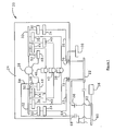
Figure 1 shows a schematic for a gas turbine engine associated with an aircraft. -
Figure 1 shows asystem 20 including anengine 24 associated with an aircraft. The electrical system forengine 24 will be described, but it should be understood that a similar second engine, not illustrated, having a similar system, may be included. Anaircraft DC bus 22 receives power from agenerator 28, as will be explained. A pair of inverter/rectifiers 30 receive the power generated by thegenerator 28, and distribute that power to theaircraft DC bus 22. Power from the inverter/rectifiers 30 passes through filters 34, and throughlines aircraft DC bus 22.Motor controllers motor 38, a lube pump and itsmotor 42, and a fuel pump and itsmotor 46. The generator as disclosed is a permanent magnet generator, but this application does extend to other type generators. - As illustrated,
generator 28 is an integrated starter-generator. However, it should be understood that this application extends not only to an integrated starter-generator operating in a generator mode, but also to stand-alone generators. - One known electrical system is disclosed in United States published patent applications
2004/0239202A1 ,2006/0226721A1 , and2006/0113967A1 . The present invention is directed to improving upon these basic systems, as will be described below. - As mentioned above, the electrical systems in these applications have utilized DC power for both the accessory motors and the aircraft DC bus. In the present invention, an
accessory bus 32 receives AC power from thegenerator 28. This high frequency AC current is utilized to drive themotors controllers aircraft engine 24, there is no necessity for providing long shielding or conduit. Thus, the use of the AC current is practical for theaccessory bus 32. - The use of high frequency AC for the engine accessory bus reduces dynamic interaction between system components. For example, in an architecture with a DC engine accessory bus, there could be undesirable voltage modulation on an engine accessory DC bus if the bus is connected to a high performance motor drive, such as a fuel pump. This phenomenon is known as a negative impedance instability. The high
frequency AC bus 32 eliminates this possibility, and provides other valuable benefits. - One concern with the basic arrangement of
system 20 occurs if a short circuit occurs on theaircraft DC bus 22. Since theaccessory motors aircraft DC bus 22, they may be drained to the short circuit on theaircraft DC bus 22. Thus, power will not flow to themotors gas turbine engines 24 and 26, and it is important to maintain their operation. - To address a potential short circuit, a
control 100 can sense when a short circuit occurs on theaircraft DC bus 22.Switch 70 is controlled by thecontrol 100. Of course, thecontrol 100 may be the main controller for the engine, and can communicate with many more items. However, for purposes of understanding this invention, all that need be understood is thecontrol 100 controls theswitch 70. - A
voltage regulator 48 receives control voltage, normally from aline 50 from theaccessory bus 32. However, analternate line 54 provides power to thevoltage regulator 48 through adiode 56. Abattery bus 60 is connected to abattery 58, and through aline 62, anddiode 66 to theaircraft DC bus 22. The battery bus also provides power through adiode 68 to aline 64 connected to thealternate control line 54. -
Figure 1 shows a normal power generation mode, such as would occur when the aircraft is in flight. The gas turbine engine drives thegenerator 28, and power is generated to power themotors aircraft DC bus 22. As shown, the power flowing to the aircraft DC bus passes through the engine accessory bus. The inverter/rectifiers 30 convert the AC power to a DC power. - In a start mode, the
switches diode 66 allows power to flow from the battery to thebus 22, and this power will then flow to the generator, to begin to operate the generator as a motor to start thegas turbine engine 24. Power will not flow from the battery through thediode 68, as there will be a higher voltage (typically 28 volts) on the accessory bus at this time than is supplied by the battery (typically 24 volts), and thediode 68 will be anti-biased. - If the
control 100 detects a short circuit on theaircraft DC bus 22, thecontrol 100 opens theswitch 70. Thediode 68 will now allow power to flow from thebattery 58 to thecontrol line 54, through thediode 56 and to thevoltage regulator 48. Since theswitch 70 is opened, power will not be drained from the engine accessory bus, but will continue to drive themotors diode 68, will continue to provide the control voltage tovoltage regulator 48 as necessary to power the voltage regulator. After some short period of time, the short circuit is corrected, and thecontrol 100 can then close theswitch 70. Once the short circuit is corrected, a higher voltage will be seen on the engine accessory bus than is supplied by thebattery 58. At that time, thediode 68 will be anti-biased and power will not flow from the battery. Thediode 66 is also anti-biased in this condition and blocks the power flow from thebattery 58 to the aircraft DC bus. - While
diodes control 100 can replace thediodes - While the
accessory bus 32 is shown as connected via the inverter/rectifier 30, and the power quality filter 34 with the aircraft DC bus, and each of thecontrollers generator 28 deliver power to these devices without theintermediate accessory bus 32. - Although an embodiment of this invention has been disclosed, a worker of ordinary skill in this art would recognize that certain modifications would come within the scope of this invention. For that reason, the following claims should be studied to determine the true scope and content of this invention.
Claims (15)
- An aircraft electrical system comprising:a generator to be driven as part of a gas turbine engine; andsaid generator supplying electrical AC power to a plurality of accessories associated with the gas turbine engine, and said generator supplying power to an aircraft DC bus in parallel with the supply to said accessories.
- The aircraft electrical system as set forth in Claim 1, including an AC accessory bus receiving electrical power from said generator, and distributing the power to said plurality of accessories.
- The aircraft electrical system as set forth in Claim 2, wherein a power conversion device converts AC power from said AC accessory bus to DC power to be delivered to said aircraft DC bus.
- The aircraft electrical system as set forth in Claim 3, wherein a rectifier converts the AC power to DC power.
- The aircraft electrical system as set forth in any preceding Claim, wherein said accessories include at least a fuel pump.
- The aircraft electrical system as set forth in any preceding Claim, wherein said accessories include at least a lube pump.
- The aircraft electrical system as set forth in any preceding Claim, wherein a switch is opened when a short is sensed on the aircraft DC bus.
- An aircraft engine comprising:a gas turbine engine;said gas turbine engine driving a generator, said generator supplying electrical AC power to a plurality of accessories associated with said gas turbine engine; andsaid generator supplying power to an aircraft DC bus in parallel with the supply to said accessories.
- The aircraft engine as set forth in Claim 8, including an AC accessory bus receiving electrical power from said generator, and distributing the power to said plurality of accessories.
- The aircraft engine as set forth in Claim 9, wherein said AC accessory bus also supplies power to said aircraft DC bus.
- The aircraft engine as set forth in Claim 10, wherein a power conversion device converts AC power from said AC accessory bus to DC power to be delivered to said aircraft DC bus.
- The aircraft engine as set forth in Claim 11, wherein a rectifier converts the AC power to DC power.
- The aircraft engine as set forth in any of Claims 8 to 12, wherein said accessories include at least a fuel pump.
- The aircraft engine as set forth in any of Claims 8 to 13, wherein said accessories include at least a lube pump.
- The aircraft engine as set forth in any of Claims 8 to 14, wherein a switch is opened when a short is sensed on the aircraft DC bus.
Applications Claiming Priority (1)
| Application Number | Priority Date | Filing Date | Title |
|---|---|---|---|
| US11/859,055 US7952220B2 (en) | 2007-09-21 | 2007-09-21 | Generator for gas turbine engine having main DC bus accessory AC bus |
Publications (3)
| Publication Number | Publication Date |
|---|---|
| EP2040370A2 true EP2040370A2 (en) | 2009-03-25 |
| EP2040370A3 EP2040370A3 (en) | 2013-12-11 |
| EP2040370B1 EP2040370B1 (en) | 2015-10-07 |
Family
ID=40261972
Family Applications (1)
| Application Number | Title | Priority Date | Filing Date |
|---|---|---|---|
| EP08252777.1A Active EP2040370B1 (en) | 2007-09-21 | 2008-08-21 | Generator for gas turbine engine having main DC bus and accessory AC bus |
Country Status (3)
| Country | Link |
|---|---|
| US (2) | US7952220B2 (en) |
| EP (1) | EP2040370B1 (en) |
| CA (2) | CA2767297C (en) |
Cited By (4)
| Publication number | Priority date | Publication date | Assignee | Title |
|---|---|---|---|---|
| EP2071692A1 (en) | 2007-12-13 | 2009-06-17 | Hamilton Sundstrand Corporation | Motor drive architecture for high frequency AC bus |
| WO2014022316A1 (en) * | 2012-07-30 | 2014-02-06 | Kawasaki Jukogyo Kabushiki Kaisha | Electric system stabilizing system for aircraft |
| EP2801719A1 (en) * | 2013-05-09 | 2014-11-12 | Rolls-Royce plc | Aircraft electrical system |
| FR3102754A1 (en) * | 2019-11-05 | 2021-05-07 | Safran | HYBRID PROPULSIVE ARCHITECTURE AND AIRCRAFT CONTAINING SUCH ARCHITECTURE |
Families Citing this family (8)
| Publication number | Priority date | Publication date | Assignee | Title |
|---|---|---|---|---|
| US8890350B2 (en) | 2012-01-13 | 2014-11-18 | Hamilton Sundstrand Corporation | Turbomachine drive arrangement |
| US20130232941A1 (en) * | 2012-03-07 | 2013-09-12 | Ge Aviation Systems Llc | Apparatus for extracting input power from the low pressure spool of a turbine engine |
| FR3015571B1 (en) * | 2013-12-23 | 2018-11-23 | Safran Helicopter Engines | METHOD AND SYSTEM FOR RELIABLY STARTING TURBOMACHINE |
| US9573539B2 (en) | 2014-08-18 | 2017-02-21 | Hamilton Sundstrand Corporation | Electric system architecture for more-electric engine accessories |
| US9771164B2 (en) | 2014-10-27 | 2017-09-26 | Hamilton Sundstrand Corporation | Electric system architecture included in a more-electric engine (MEE) system |
| US10087902B2 (en) | 2015-05-11 | 2018-10-02 | Sikorsky Aircraft Corporation | Power limiting generator control unit (GCU) |
| FR3087960B1 (en) * | 2018-10-31 | 2021-06-04 | Safran | ELECTRICAL ENERGY CONVERSION AND TRANSPORT SYSTEM FOR THE INTERNAL HYBRIDATION OF A TURBOREACTOR AIRCRAFT |
| WO2023091579A1 (en) * | 2021-11-17 | 2023-05-25 | Verdego Aero, Inc. | Split turbocharger having independent electric turbine and electric compressor components |
Citations (3)
| Publication number | Priority date | Publication date | Assignee | Title |
|---|---|---|---|---|
| US20040239202A1 (en) | 2003-05-27 | 2004-12-02 | Dooley Kevin Allan | Architecture for electric machine |
| US20060113967A1 (en) | 2004-11-26 | 2006-06-01 | Dooley Kevin A | Saturation control of electric machine |
| US20060226721A1 (en) | 2003-05-27 | 2006-10-12 | Dooley Kevin A | Saturation control of electric machine |
Family Cites Families (11)
| Publication number | Priority date | Publication date | Assignee | Title |
|---|---|---|---|---|
| US5939800A (en) | 1998-02-11 | 1999-08-17 | Alliedsignal Inc. | Aircraft electrical power system including air conditioning system generator |
| GB0128662D0 (en) | 2001-11-30 | 2002-01-23 | Rolls Royce Plc | Improvements in or relating to generator arrangements |
| US6778414B2 (en) * | 2002-12-20 | 2004-08-17 | The Boeing Company | Distributed system and methodology of electrical power regulation, conditioning and distribution on an aircraft |
| US6920023B2 (en) | 2003-03-21 | 2005-07-19 | Pratt & Whitney Canada Corp. | Current limiting means for a generator |
| DE10348693B4 (en) | 2003-10-16 | 2009-06-04 | Hilti Aktiengesellschaft | Electrical connection device for hand tool accessories |
| US7064526B2 (en) | 2004-04-23 | 2006-06-20 | Astronics Advanced Electronic Systems Corp. | Fault tolerant architecture for permanent magnet starter generator subsystem |
| US7400065B2 (en) * | 2004-08-24 | 2008-07-15 | Honeywell International Inc. | Electrical power distribution system and method with active load control |
| FR2882200B1 (en) * | 2005-02-17 | 2015-05-01 | Hispano Suiza Sa | ELECTRICAL POWER SUPPLY FOR GAS TURBINE AIRCRAFT ENGINE EQUIPMENT |
| US20060267540A1 (en) * | 2005-05-27 | 2006-11-30 | Parker Hannifin Corporation | Pump driven by dual wound variable frequency induction motor |
| US7612514B2 (en) * | 2006-11-09 | 2009-11-03 | Honeywell International Inc. | Architecture and a multiple function power converter for aircraft |
| US7550866B2 (en) * | 2006-12-20 | 2009-06-23 | The Boeing Company | Vehicular power distribution system and method |
-
2007
- 2007-09-21 US US11/859,055 patent/US7952220B2/en active Active
-
2008
- 2008-08-20 CA CA2767297A patent/CA2767297C/en active Active
- 2008-08-20 CA CA2638961A patent/CA2638961C/en not_active Expired - Fee Related
- 2008-08-21 EP EP08252777.1A patent/EP2040370B1/en active Active
-
2011
- 2011-02-04 US US13/020,836 patent/US8319369B2/en active Active
Patent Citations (3)
| Publication number | Priority date | Publication date | Assignee | Title |
|---|---|---|---|---|
| US20040239202A1 (en) | 2003-05-27 | 2004-12-02 | Dooley Kevin Allan | Architecture for electric machine |
| US20060226721A1 (en) | 2003-05-27 | 2006-10-12 | Dooley Kevin A | Saturation control of electric machine |
| US20060113967A1 (en) | 2004-11-26 | 2006-06-01 | Dooley Kevin A | Saturation control of electric machine |
Cited By (7)
| Publication number | Priority date | Publication date | Assignee | Title |
|---|---|---|---|---|
| EP2071692A1 (en) | 2007-12-13 | 2009-06-17 | Hamilton Sundstrand Corporation | Motor drive architecture for high frequency AC bus |
| WO2014022316A1 (en) * | 2012-07-30 | 2014-02-06 | Kawasaki Jukogyo Kabushiki Kaisha | Electric system stabilizing system for aircraft |
| US10029631B2 (en) | 2012-07-30 | 2018-07-24 | Kawasaki Jukogyo Kabushiki Kaisha | Electric system stabilizing system for aircraft |
| EP2801719A1 (en) * | 2013-05-09 | 2014-11-12 | Rolls-Royce plc | Aircraft electrical system |
| US9776583B2 (en) | 2013-05-09 | 2017-10-03 | Rolls-Royce Plc | Aircraft electrical system |
| FR3102754A1 (en) * | 2019-11-05 | 2021-05-07 | Safran | HYBRID PROPULSIVE ARCHITECTURE AND AIRCRAFT CONTAINING SUCH ARCHITECTURE |
| WO2021089948A1 (en) | 2019-11-05 | 2021-05-14 | Safran | Hybrid propulsion architecture and aircraft containing such an architecture |
Also Published As
| Publication number | Publication date |
|---|---|
| US20090079261A1 (en) | 2009-03-26 |
| US7952220B2 (en) | 2011-05-31 |
| CA2767297C (en) | 2017-07-04 |
| CA2638961A1 (en) | 2009-03-21 |
| US8319369B2 (en) | 2012-11-27 |
| CA2638961C (en) | 2012-03-20 |
| EP2040370A3 (en) | 2013-12-11 |
| EP2040370B1 (en) | 2015-10-07 |
| US20110169328A1 (en) | 2011-07-14 |
| CA2767297A1 (en) | 2009-03-21 |
Similar Documents
| Publication | Publication Date | Title |
|---|---|---|
| EP2040370B1 (en) | Generator for gas turbine engine having main DC bus and accessory AC bus | |
| CA2638648C (en) | Generator for gas turbine engine having dc bus fault short circuit control using a battery | |
| EP2028758B1 (en) | Engine having power bus fault short circuit control with a disconnection switch | |
| US8237416B2 (en) | More electric engine with regulated permanent magnet machines | |
| US7936086B2 (en) | Paralleled HVDC bus electrical power system architecture | |
| US9873518B2 (en) | Electrical architecture for an aircraft, an aircraft, and a method of using it | |
| US8218341B2 (en) | Integrated aircraft power conditioning unit | |
| US8525492B2 (en) | Electric power generation system with multiple alternators driven by a common prime mover | |
| US8581425B2 (en) | Systems and methods involving electrical start and power generation | |
| US11053013B2 (en) | Unit for generating non-propulsive electrical power | |
| US7117683B2 (en) | Main engine electric start system | |
| WO2020053502A3 (en) | Hybrid propulsion assembly for aircraft | |
| EP2659116B1 (en) | Integrated generator and motor pump | |
| US9637007B2 (en) | Supplying electric traction motors of a rail vehicle with electrical energy using a plurality of internal combustion engines | |
| EP2045910B1 (en) | Starter/generator system with control to address a voltage rise | |
| US7710058B2 (en) | Motor drive architecture for high frequency AC bus | |
| RU2623643C1 (en) | Method of regulating the voltage in gas turbine - generator system for power supply of electrical drives of a vehicle | |
| EP2595309A1 (en) | Systems and methods involving electrical start and power generation |
Legal Events
| Date | Code | Title | Description |
|---|---|---|---|
| PUAI | Public reference made under article 153(3) epc to a published international application that has entered the european phase |
Free format text: ORIGINAL CODE: 0009012 |
|
| AK | Designated contracting states |
Kind code of ref document: A2 Designated state(s): AT BE BG CH CY CZ DE DK EE ES FI FR GB GR HR HU IE IS IT LI LT LU LV MC MT NL NO PL PT RO SE SI SK TR |
|
| AX | Request for extension of the european patent |
Extension state: AL BA MK RS |
|
| PUAL | Search report despatched |
Free format text: ORIGINAL CODE: 0009013 |
|
| AK | Designated contracting states |
Kind code of ref document: A3 Designated state(s): AT BE BG CH CY CZ DE DK EE ES FI FR GB GR HR HU IE IS IT LI LT LU LV MC MT NL NO PL PT RO SE SI SK TR |
|
| AX | Request for extension of the european patent |
Extension state: AL BA MK RS |
|
| RIC1 | Information provided on ipc code assigned before grant |
Ipc: H02J 4/00 20060101ALI20131101BHEP Ipc: H02P 9/30 20060101AFI20131101BHEP |
|
| 17P | Request for examination filed |
Effective date: 20140611 |
|
| RBV | Designated contracting states (corrected) |
Designated state(s): AT BE BG CH CY CZ DE DK EE ES FI FR GB GR HR HU IE IS IT LI LT LU LV MC MT NL NO PL PT RO SE SI SK TR |
|
| AKX | Designation fees paid |
Designated state(s): DE FR GB |
|
| RIC1 | Information provided on ipc code assigned before grant |
Ipc: H02J 4/00 20060101ALI20150120BHEP Ipc: H02P 9/30 20060101AFI20150120BHEP |
|
| GRAP | Despatch of communication of intention to grant a patent |
Free format text: ORIGINAL CODE: EPIDOSNIGR1 |
|
| INTG | Intention to grant announced |
Effective date: 20150331 |
|
| GRAS | Grant fee paid |
Free format text: ORIGINAL CODE: EPIDOSNIGR3 |
|
| GRAA | (expected) grant |
Free format text: ORIGINAL CODE: 0009210 |
|
| AK | Designated contracting states |
Kind code of ref document: B1 Designated state(s): DE FR GB |
|
| REG | Reference to a national code |
Ref country code: GB Ref legal event code: FG4D |
|
| REG | Reference to a national code |
Ref country code: DE Ref legal event code: R096 Ref document number: 602008040503 Country of ref document: DE |
|
| REG | Reference to a national code |
Ref country code: DE Ref legal event code: R097 Ref document number: 602008040503 Country of ref document: DE |
|
| REG | Reference to a national code |
Ref country code: FR Ref legal event code: PLFP Year of fee payment: 9 |
|
| PLBE | No opposition filed within time limit |
Free format text: ORIGINAL CODE: 0009261 |
|
| STAA | Information on the status of an ep patent application or granted ep patent |
Free format text: STATUS: NO OPPOSITION FILED WITHIN TIME LIMIT |
|
| 26N | No opposition filed |
Effective date: 20160708 |
|
| REG | Reference to a national code |
Ref country code: FR Ref legal event code: PLFP Year of fee payment: 10 |
|
| REG | Reference to a national code |
Ref country code: FR Ref legal event code: PLFP Year of fee payment: 11 |
|
| REG | Reference to a national code |
Ref country code: DE Ref legal event code: R082 Ref document number: 602008040503 Country of ref document: DE |
|
| PGFP | Annual fee paid to national office [announced via postgrant information from national office to epo] |
Ref country code: GB Payment date: 20230720 Year of fee payment: 16 |
|
| PGFP | Annual fee paid to national office [announced via postgrant information from national office to epo] |
Ref country code: FR Payment date: 20230720 Year of fee payment: 16 Ref country code: DE Payment date: 20230720 Year of fee payment: 16 |