EP2039936A1 - Scroll compressor - Google Patents
Scroll compressor Download PDFInfo
- Publication number
- EP2039936A1 EP2039936A1 EP07768242A EP07768242A EP2039936A1 EP 2039936 A1 EP2039936 A1 EP 2039936A1 EP 07768242 A EP07768242 A EP 07768242A EP 07768242 A EP07768242 A EP 07768242A EP 2039936 A1 EP2039936 A1 EP 2039936A1
- Authority
- EP
- European Patent Office
- Prior art keywords
- scroll
- orbital
- fixed
- volume ratio
- discharge hole
- Prior art date
- Legal status (The legal status is an assumption and is not a legal conclusion. Google has not performed a legal analysis and makes no representation as to the accuracy of the status listed.)
- Withdrawn
Links
- 238000007906 compression Methods 0.000 claims abstract description 77
- 230000006835 compression Effects 0.000 claims abstract description 74
- 239000012530 fluid Substances 0.000 claims abstract description 24
- 230000001052 transient effect Effects 0.000 claims abstract description 16
- 230000015572 biosynthetic process Effects 0.000 claims abstract description 3
- 230000002093 peripheral effect Effects 0.000 claims description 13
- 238000000034 method Methods 0.000 claims description 9
- 239000003507 refrigerant Substances 0.000 description 31
- CURLTUGMZLYLDI-UHFFFAOYSA-N Carbon dioxide Chemical compound O=C=O CURLTUGMZLYLDI-UHFFFAOYSA-N 0.000 description 9
- 239000003921 oil Substances 0.000 description 9
- 238000004519 manufacturing process Methods 0.000 description 7
- 238000004891 communication Methods 0.000 description 5
- 238000005057 refrigeration Methods 0.000 description 4
- 239000010687 lubricating oil Substances 0.000 description 3
- 238000013459 approach Methods 0.000 description 2
- 238000012545 processing Methods 0.000 description 2
- XLYOFNOQVPJJNP-UHFFFAOYSA-N water Substances O XLYOFNOQVPJJNP-UHFFFAOYSA-N 0.000 description 2
- BVKZGUZCCUSVTD-UHFFFAOYSA-N carbonic acid Chemical compound OC(O)=O BVKZGUZCCUSVTD-UHFFFAOYSA-N 0.000 description 1
- 230000007423 decrease Effects 0.000 description 1
- 230000003111 delayed effect Effects 0.000 description 1
- 238000011161 development Methods 0.000 description 1
- 238000010586 diagram Methods 0.000 description 1
- 238000007599 discharging Methods 0.000 description 1
- 230000008030 elimination Effects 0.000 description 1
- 238000003379 elimination reaction Methods 0.000 description 1
- 239000000314 lubricant Substances 0.000 description 1
- 239000007787 solid Substances 0.000 description 1
- 238000010792 warming Methods 0.000 description 1
- 239000013585 weight reducing agent Substances 0.000 description 1
Images
Classifications
-
- F—MECHANICAL ENGINEERING; LIGHTING; HEATING; WEAPONS; BLASTING
- F04—POSITIVE - DISPLACEMENT MACHINES FOR LIQUIDS; PUMPS FOR LIQUIDS OR ELASTIC FLUIDS
- F04C—ROTARY-PISTON, OR OSCILLATING-PISTON, POSITIVE-DISPLACEMENT MACHINES FOR LIQUIDS; ROTARY-PISTON, OR OSCILLATING-PISTON, POSITIVE-DISPLACEMENT PUMPS
- F04C18/00—Rotary-piston pumps specially adapted for elastic fluids
- F04C18/02—Rotary-piston pumps specially adapted for elastic fluids of arcuate-engagement type, i.e. with circular translatory movement of co-operating members, each member having the same number of teeth or tooth-equivalents
- F04C18/0207—Rotary-piston pumps specially adapted for elastic fluids of arcuate-engagement type, i.e. with circular translatory movement of co-operating members, each member having the same number of teeth or tooth-equivalents both members having co-operating elements in spiral form
- F04C18/0215—Rotary-piston pumps specially adapted for elastic fluids of arcuate-engagement type, i.e. with circular translatory movement of co-operating members, each member having the same number of teeth or tooth-equivalents both members having co-operating elements in spiral form where only one member is moving
-
- F—MECHANICAL ENGINEERING; LIGHTING; HEATING; WEAPONS; BLASTING
- F04—POSITIVE - DISPLACEMENT MACHINES FOR LIQUIDS; PUMPS FOR LIQUIDS OR ELASTIC FLUIDS
- F04C—ROTARY-PISTON, OR OSCILLATING-PISTON, POSITIVE-DISPLACEMENT MACHINES FOR LIQUIDS; ROTARY-PISTON, OR OSCILLATING-PISTON, POSITIVE-DISPLACEMENT PUMPS
- F04C18/00—Rotary-piston pumps specially adapted for elastic fluids
- F04C18/02—Rotary-piston pumps specially adapted for elastic fluids of arcuate-engagement type, i.e. with circular translatory movement of co-operating members, each member having the same number of teeth or tooth-equivalents
- F04C18/0207—Rotary-piston pumps specially adapted for elastic fluids of arcuate-engagement type, i.e. with circular translatory movement of co-operating members, each member having the same number of teeth or tooth-equivalents both members having co-operating elements in spiral form
- F04C18/0246—Details concerning the involute wraps or their base, e.g. geometry
- F04C18/0269—Details concerning the involute wraps
Definitions
- the present invention relates to a scroll compressor, and, more particularly, to a scroll compressor suitable for compression of a working fluid with a high working pressure.
- This kind of scroll compressor has a scroll unit which carries out a series of processes from suction of a working fluid to discharge thereof through compression thereof.
- the scroll unit includes a fixed scroll and an orbital scroll, which respectively have spiral laps to be engaged with each other, and end plates supporting the spiral laps.
- the orbital scroll makes a revolution movement about the axial of the fixed scroll without rotating, i.e., makes an orbital movement. This increases the space defined between the fixed and orbital scrolls or the volume of the compression chamber, thereby allowing the series of processes to be carried out.
- the discharge hole is positioned nearly at the center portion of the end plate to allow the compression chamber and the discharge chamber to communicate with each other at the end stage of compression of the working fluid, while a plurality of the communication passages are positioned near the discharge hole to allow the compression chamber and the discharge chamber to communicate with each other via a valve during compression of the working fluid.
- Patent documents 1 Japanese Patent No. 3635826
- the refrigeration cycle uses a working fluid which has a small global warming potential.
- a working fluid which has a small global warming potential.
- CO 2 carbonic acid
- the operation pressure of the CO 2 gas varies according to the outside air condition or the like. Therefore, the CO 2 gas may be excessively compressed, and such excessive compression lowers the performance of the refrigeration cycle.
- a scroll compressor having a scroll unit which carries out a series of processes from suction of a working fluid to discharge thereof through compression thereof, the scroll unit including a fixed scroll having a single discharge hole, and an orbital scroll that makes an orbital movement with respect to the fixed scroll and forms two transient compression chambers into which the working fluid is sucked, in cooperation with the fixed scroll, and then forms the transient compression chambers into a final compression chamber at a center portion of the scroll unit, wherein the transient compression chambers have a volume ratio of 0.5 or greater, which expresses a ratio of a volume of the transient compression chambers immediately before formation of the final compression chamber to a suction volume of the transient compression chambers at a time of sucking the working fluid.
- the volume ratio of the two transient compression chambers formed in the scroll unit is kept at 0.5 or greater until the final compression chamber is formed. Even in the case where the scroll unit compresses a working fluid with a high working pressure, therefore, the compression ratio of the working fluid is suppressed smaller, thus preventing excessive compression of the working fluid.
- the scroll unit merely has a single discharge hole, it is unnecessary to adopt the technique of the Patent Document 1 or processing a plurality of communication passages with respect to the fixed scroll, and a valve which opens or closes each of the communication passages. As a result, the configuration of the scroll unit becomes simpler and the manufacturing cost becomes lower.
- the fixed scroll according to the present invention can include a fixed end plate having the discharge hole formed therein, a fixed spiral lap projecting from the fixed end plate toward the orbital scroll, and a volume ratio determining portion formed as an inner peripheral end of the fixed spiral lap and positioned near the discharge hole.
- the volume ratio determining portion fills in space near the discharge hole, and has an outer shape partially surrounding an opening edge of the discharge hole.
- the volume ratio determining portion preferably has an inner wall adjoining the discharge hole, and an outer wall which connects the inner wall to the outer wall of the fixed spiral lap, and has an arc shape projecting outward as viewed in a radial direction of the fixed spiral lap.
- the volume ratio determining portion can easily be obtained by merely modifying the profile of an existing fixed spiral lap. This can make the manufacturing cost of the scroll compressor while keeping the performance thereof.
- the volume ratio determining portion have a cavity in which case the weight reduction of the scroll compressor can be achieved.
- the orbital scroll includes an orbital end plate facing the fixed end plate, and an orbital spiral lap projecting from the orbital end plate toward the fixed scroll and being engaged with the fixed spiral lap, wherein during the orbital movement of the orbital scroll, the orbital spiral lap has an inner peripheral end which periodically contacts the volume ratio determining portion.
- Such an orbital spiral lap can also be easily obtained by merely modifying the profile of an existing orbital spiral lap.
- a compressor 1 in Fig. 1 is inserted into a circulation path for circulating a working fluid in an air conditioner or a heat pump type water heater, etc., and uses, for example, a CO 2 refrigerant (hereinafter called "refrigerant") as the working fluid.
- the compressor 1 carries out suction of the refrigerant from a circulation path, compression of the sucked refrigerant, and discharge of the compressed refrigerant to the circulation path, thereby letting the refrigerant circulate in the circulation path.
- the compressor 1 has a housing 2.
- the housing 2 includes a cylindrical body portion 4 extending in the up and down direction, and an upper lid 6 and a lower lid 8 which respectively closes the upper end and lower end of the body portion 4 airtightly, defining an airtight chamber inside.
- the lower portion of the housing 2 is formed as an oil chamber 9 for storing a lubricant.
- An electric motor 10 is accommodated in the body portion 4, and has a hollow drive shaft 12 at the center thereof. When power is supplied to the motor 10, the drive shaft 12 is rotated in one direction.
- the upper end portion of the drive shaft 12 is rotatably supported by an upper frame 14 via a bearing 16, and the upper frame 14 is fixed to the body portion 4.
- the lower end portion of the drive shaft 12 is rotatably supported by a lower frame 18 via a bearing 20, and the lower frame 18 is also fixed to the body portion 4.
- An oil pump 22 is attached to the lower end of the drive shaft 12, and is driven by the rotation of the drive shaft 12. When the oil pump 22 is driven, the oil pump 22 sucks a lubricating oil in the oil chamber 9, and discharges the sucked lubricating oil into the drive shaft 12 or an oil passage 24 defined in the drive shaft 12.
- the oil passage 24 extends in the axial direction of the drive shaft 12, so that the lubricating oil discharged into the oil passage 24 is fed through the oil passage 24 toward the upper end of the drive shaft 12, and is then supplied to each sliding portion of the motor 10 and a scroll unit to be described later from the upper end of the drive shaft 12.
- the scroll unit 30 is arranged in the body portion 4, and positioned above the motor 10.
- the scroll unit 30 carries out a series of processes from suction of the refrigerant and discharge thereof through compression thereof.
- the scroll unit 30 includes an orbital scroll 52 and a fixed scroll 32.
- the orbital scroll 52 has an end plate 54 and a spiral lap 56 formed integral with the end plate 54 and projecting toward an end plate 34 of the fixed scroll 32 from the end plate 54.
- the fixed scroll 32 has the end plate 34 and a spiral lap 36 formed integral with the end plate 34 and projecting toward the end plate 54 of the orbital scroll 52.
- the spiral laps 34, 56 have spiral shapes to engage with each other, and the spiral shapes are defined substantially by the involution.
- the spiral laps 36, 56 cooperate to form a plurality of compression chambers. More specifically, a compression chamber is formed at the outer peripheries of the spiral laps 36, 56 by the revolution movement of the orbital scroll 52, and the volumes of the formed compression chamber decreases as it moves toward the centers of the spiral laps 36, 56.
- a boss 66 is formed at the bottom side of the end plate 54.
- the boss 66 is rotatably supported by an eccentric shaft 26 via a bearing 28, the eccentric shaft 26 projecting integrally from the upper end of the drive shaft 12.
- the rotation of the orbital scroll 52 is inhibited by a plurality of pins 68 which protrude toward the upper frame 14 from the end plate 54 and are positioned in holes of the upper frame 14.
- the orbital radius of the pins 68 is determined by the holes.
- the fixed scroll 32 is fixed to the upper frame 14, and a discharge chamber 80 is defined in the housing 2 between the end plate 34 of fixed scroll 32 and the upper lid 6.
- the end plate 34 has a single discharge hole 50 which is positioned slightly eccentric from the center of the end plate 34, and penetrates the end plate 34.
- a discharge valve 82 is attached to the end plate 34, and opens and closes a discharge hole 82.
- a suction pipe 84 is connected to the body portion 4 to guide the refrigerant into the body portion 4.
- the ratio of the volume V to the suction volume Vc or the volume ratio V/Vc is set to 0.5 or greater.
- This setting of the volume ratio V/Vc is optimal when a compressor for a heat pump type water heater, which is recently commercialized, is used to compress a CO 2 refrigerant.
- the scroll unit 30 of the embodiment has a volume ratio setting portion at the inner peripheral end of the spiral lap 36 to discharge the compressed refrigerant from the scroll unit 30 at the crank angle which determines the volume ratio V/Vc to 0.5 or greater, the position of the inner peripheral end of the spiral lap 56, i.e., the involute starting position of the spiral lap 56 is determined.
- the volume ratio setting portion of the spiral lap 36 is formed as a space filling potion 38 which increases the volume of the inner peripheral end of the spiral lap 36, and the space filling portion 38 fills the space at approximately the center portion of the end plate 34.
- the space filling portion 38 like the spiral lap 36, projects toward the orbital scroll 52 from the end plate 34.
- the outer shape of the space filling portion 38 is made by an inner wall 40 facing the discharge hole 50 side and an outer wall 42 with an arc shape projecting outward in the radial direction of the spiral lap 36.
- the inner wall 40 extends toward the discharge hole 50 from the inner peripheral surface of the spiral lap 36, then surrounds about a half of the opening edge of the discharge hole 50 (right-hand side of the opening edge of the discharge hole 50 in Fig. 2 ), and then extends toward the outer wall 42 from the discharge hole 50 to be connected to the terminal end of the outer wall 42.
- the inner peripheral end of the spiral lap 56 is formed as a retreat end 58 retreating in the spiral direction of the spiral lap 56 to avoid interference with the space filling portion 38.
- the retreat end 58 turns to come close and away from the inner wall 40 of the space filling portion 38 positioned above the discharge hole 50 shown in Fig. 4 .
- the spiral lap 56 and the space filling portion 38 of the spiral lap 36 cooperate to form a final compression chamber 74 which achieves the compression ratio of the refrigerant corresponding to the volume ratio V/Vc.
- the orbital scroll 52 when the drive shaft 12 is driven, the orbital scroll 52 makes an orbital movement with respect to the fixed scroll 32 without rotating.
- Such an orbital movement of the orbital scroll 52 allows the refrigerant in the body portion 4 to be sucked into the scroll unit 30 from the outer surface of the scroll unit 30, after which the scroll unit 30 initiates the compression process of the sucked refrigerant.
- the retreat end 58 of the spiral lap 56 contacts the inner wall 40 of the space filling portion 38, forming two compression chambers 70, 72 sandwiching the spiral lap 56. More specifically, the compression chamber 70 is positioned outside the spiral lap 56, while the compression chamber 72 is positioned inside the spiral lap 56. Those compression chambers 70, 72 are completely separated by the retreat end 58 of the spiral lap 56. With regard to the volumes of the compression chambers 70, 72, their volume ratios V/Vc both exceed 0.5.
- the compression chambers 70, 72 appears respectively at two refrigerant intake positions spaced apart from each other in the diametric direction of the scroll unit 30, and are moved to positions at the crank angle of 0°.
- the volume of the compression chamber 74 is reduced.
- the volume of the compression chamber 74 is reduced to a range of 0.5 times the suction volume Vc or less (see Fig. 3 ).
- the discharge valve 82 is opened.
- the compressed refrigerant in the compression chamber 74 is discharged into the discharge chamber 80 via the discharge valve 82.
- the discharge pressure of the refrigerant equivalent to the compression ratio of about 2.0 or greater is generated.
- the compressed refrigerant discharged into the discharge chamber 80 circulates in the housing 2, and is then fed out through a discharge pipe 86.
- the discharge pipe 86 is attached to the upper lid 6 to be connected to the discharge chamber 80. That is, in case of the embodiment, the discharge chamber 80 is not defined in the housing 2, and communicates with the inside of the body portion 4 accommodating the motor 10.
- the volume ratios of the volumes of the compression chambers 70, 72 immediately before the single compression chamber 74 is finally formed from the two compression chambers 70, 72 are set to 0.5 or greater. Therefore, even when the scroll unit 30 is operated in either the summer season where the compression efficiency of the refrigerant becomes lower or the winter season where the compression efficiency of the refrigerant is high due to a change in the density of the refrigerant, the discharge pressure of the refrigerant from the discharge hole of the scroll unit does not rise excessively, preventing excessive compression of the refrigerant.
- the scroll unit 30 needs only the single discharge hole 50, it is unnecessary to apply the technique of the Patent Document 1 to the scroll unit 30.
- the structure of the scroll unit 30 becomes simpler, the operational reliability thereof can be kept high, and further, the manufacturing cost of the scroll unit 30 becomes lower.
- the elimination of the need for communicating holes can make the discharge hole 50 larger.
- the increased diameter of the discharge hole 50 reduces the pressure loss in the discharge hole 50, which significantly contributes to reduction of the power needed by the scroll unit 30.
- the condition of determining the volume ratio V/Vc to 0.5 or greater is achieved merely by forming the space filling portion 38 at the inner peripheral end of the spiral lap 36 of the fixed scroll 32 and forming the retreat end 58 at the inner peripheral end of the spiral lap 56 of the orbital scroll 52. Therefore, excessive compression of the refrigerant is prevented merely by modifying the profiles of the existing spiral laps 36, 56. As a result, reduction in the manufacturing cost of the scroll unit 30 can be achieved surely while maintaining the performance of the unit 30.
- the space filling portion 38 is not limited to be solid, but may have a cavity 43 at the center as shown in Fig. 5 . In this case, the weight of the fixed scroll 32 can be reduced.
- the starting angles of the spiral laps 36, 56 can be delayed by about 10° to about 45° in terms of the crank angle.
- forming the inner peripheral ends of the spiral laps 36, 56 as retreat ends can achieve the aforementioned condition of the volume ratio V/Vc.
- the present invention is applicable to an asymmetrical type of scroll unit which forms compression chambers 70, 72 with different shapes as well as a symmetrical type of scroll unit which forms compression chambers 70, 72 with similar shapes.
Landscapes
- Engineering & Computer Science (AREA)
- Mechanical Engineering (AREA)
- General Engineering & Computer Science (AREA)
- Rotary Pumps (AREA)
- Applications Or Details Of Rotary Compressors (AREA)
Abstract
A scroll compressor has a scroll unit (30) that includes a fixed scroll (32) having a single discharge hole (50), and an orbital scroll (52) which makes an orbital movement with respect to the fixed scroll (32), those scrolls (32, 52) cooperate with each other to form two transient compression chambers (70, 72) into which a working fluid is sucked, and then form the transient compression chambers (70, 72) into a final compression chamber (74) at a center portion of the scroll unit (30), and the transient compression chambers have a volume ratio of 0.5 or greater, which expresses the ratio of a volume of the transient compression chambers (70, 72) immediately before formation of the final compression chamber (74) to a suction volume of the transient compression chambers (70, 72) at a time of sucking the working fluid.
Description
- The present invention relates to a scroll compressor, and, more particularly, to a scroll compressor suitable for compression of a working fluid with a high working pressure.
- This kind of scroll compressor has a scroll unit which carries out a series of processes from suction of a working fluid to discharge thereof through compression thereof. In detail, the scroll unit includes a fixed scroll and an orbital scroll, which respectively have spiral laps to be engaged with each other, and end plates supporting the spiral laps. The orbital scroll makes a revolution movement about the axial of the fixed scroll without rotating, i.e., makes an orbital movement. This increases the space defined between the fixed and orbital scrolls or the volume of the compression chamber, thereby allowing the series of processes to be carried out.
- When the operational speed of the compressor is varied, the suction pressure and the discharge pressure of the working fluid both change, and this pressure change may cause excessive compression of the working fluid. There is known a scroll unit which prevents such excessive compression of a working fluid (refer to
Patent Document 1, for example). In this scroll unit, a plurality of communication passages as well as a discharge hole to discharge the compressed working fluid to a discharge chamber are formed in the end plate of the fixed scroll. Specifically, the discharge hole is positioned nearly at the center portion of the end plate to allow the compression chamber and the discharge chamber to communicate with each other at the end stage of compression of the working fluid, while a plurality of the communication passages are positioned near the discharge hole to allow the compression chamber and the discharge chamber to communicate with each other via a valve during compression of the working fluid.
Patent documents 1: Japanese Patent No.3635826 - By the way, recently, development of the refrigeration cycle which has taken into consideration global environment has progressed. The refrigeration cycle uses a working fluid which has a small global warming potential. As an example of this kind of working fluid, there is natural CO2 (carbonic acid) gas. During the operation of a refrigeration cycle, the operation pressure of the CO2 gas varies according to the outside air condition or the like. Therefore, the CO2 gas may be excessively compressed, and such excessive compression lowers the performance of the refrigeration cycle.
- It is supposed that the use of the technique of the
Patent Document 1 overcomes the excessive compression of the CO2 gas. However, the communication passages and valve of thePatent Document 1 not only complicates the configuration of the scroll unit but also increases the manufacturing cost thereof. Because the compression ratio of the CO2 gas changes considerably, it is necessary to use the discharge valve that can cope with the change, and this requirement also becomes a big factor to increase the manufacturing cost of the scroll unit. - It is an object of the present invention to provide a scroll compressor that can surely prevent excessive compression of a working fluid by employing a simple configuration which does not increase the manufacturing cost.
- To achieve the object, a scroll compressor having a scroll unit which carries out a series of processes from suction of a working fluid to discharge thereof through compression thereof, the scroll unit including a fixed scroll having a single discharge hole, and an orbital scroll that makes an orbital movement with respect to the fixed scroll and forms two transient compression chambers into which the working fluid is sucked, in cooperation with the fixed scroll, and then forms the transient compression chambers into a final compression chamber at a center portion of the scroll unit, wherein the transient compression chambers have a volume ratio of 0.5 or greater, which expresses a ratio of a volume of the transient compression chambers immediately before formation of the final compression chamber to a suction volume of the transient compression chambers at a time of sucking the working fluid.
- According to the scroll compressor, the volume ratio of the two transient compression chambers formed in the scroll unit is kept at 0.5 or greater until the final compression chamber is formed. Even in the case where the scroll unit compresses a working fluid with a high working pressure, therefore, the compression ratio of the working fluid is suppressed smaller, thus preventing excessive compression of the working fluid.
- Since the scroll unit merely has a single discharge hole, it is unnecessary to adopt the technique of the
Patent Document 1 or processing a plurality of communication passages with respect to the fixed scroll, and a valve which opens or closes each of the communication passages. As a result, the configuration of the scroll unit becomes simpler and the manufacturing cost becomes lower. - The fixed scroll according to the present invention can include a fixed end plate having the discharge hole formed therein, a fixed spiral lap projecting from the fixed end plate toward the orbital scroll, and a volume ratio determining portion formed as an inner peripheral end of the fixed spiral lap and positioned near the discharge hole.
- Specifically, the volume ratio determining portion fills in space near the discharge hole, and has an outer shape partially surrounding an opening edge of the discharge hole. The volume ratio determining portion preferably has an inner wall adjoining the discharge hole, and an outer wall which connects the inner wall to the outer wall of the fixed spiral lap, and has an arc shape projecting outward as viewed in a radial direction of the fixed spiral lap.
- According to the fixed scroll, the volume ratio determining portion can easily be obtained by merely modifying the profile of an existing fixed spiral lap. This can make the manufacturing cost of the scroll compressor while keeping the performance thereof.
- Further, it is preferable that the volume ratio determining portion have a cavity in which case the weight reduction of the scroll compressor can be achieved.
- The orbital scroll includes an orbital end plate facing the fixed end plate, and an orbital spiral lap projecting from the orbital end plate toward the fixed scroll and being engaged with the fixed spiral lap, wherein during the orbital movement of the orbital scroll, the orbital spiral lap has an inner peripheral end which periodically contacts the volume ratio determining portion. Such an orbital spiral lap can also be easily obtained by merely modifying the profile of an existing orbital spiral lap.
-
-
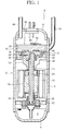
Fig. 1 illustrates a longitudinal cross-sectional view of a scroll compressor according to one embodiment of the present invention. -
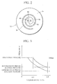
Fig. 2 illustrates a front view of a fixed scroll inFig. 1 . -
Fig. 3 is a graph showing the relationship between the pressure in a compression chamber and the volume ratio when the scroll unit inFig. 1 is used to compress a CO2 refrigerant. -
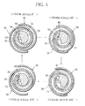
Fig. 4 is a diagram illustrating a compression process by the scroll unit inFig. 1 . -
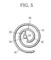
Fig. 5 illustrates a cross-sectional view of a fixed scroll according to another embodiment. - A
compressor 1 inFig. 1 is inserted into a circulation path for circulating a working fluid in an air conditioner or a heat pump type water heater, etc., and uses, for example, a CO2 refrigerant (hereinafter called "refrigerant") as the working fluid. Thecompressor 1 carries out suction of the refrigerant from a circulation path, compression of the sucked refrigerant, and discharge of the compressed refrigerant to the circulation path, thereby letting the refrigerant circulate in the circulation path. - More specifically, the
compressor 1 has ahousing 2. Thehousing 2 includes acylindrical body portion 4 extending in the up and down direction, and anupper lid 6 and alower lid 8 which respectively closes the upper end and lower end of thebody portion 4 airtightly, defining an airtight chamber inside. The lower portion of thehousing 2 is formed as anoil chamber 9 for storing a lubricant. - An
electric motor 10 is accommodated in thebody portion 4, and has ahollow drive shaft 12 at the center thereof. When power is supplied to themotor 10, thedrive shaft 12 is rotated in one direction. The upper end portion of thedrive shaft 12 is rotatably supported by anupper frame 14 via abearing 16, and theupper frame 14 is fixed to thebody portion 4. - The lower end portion of the
drive shaft 12 is rotatably supported by alower frame 18 via abearing 20, and thelower frame 18 is also fixed to thebody portion 4. An oil pump 22 is attached to the lower end of thedrive shaft 12, and is driven by the rotation of thedrive shaft 12. When the oil pump 22 is driven, the oil pump 22 sucks a lubricating oil in theoil chamber 9, and discharges the sucked lubricating oil into thedrive shaft 12 or anoil passage 24 defined in thedrive shaft 12. Theoil passage 24 extends in the axial direction of thedrive shaft 12, so that the lubricating oil discharged into theoil passage 24 is fed through theoil passage 24 toward the upper end of thedrive shaft 12, and is then supplied to each sliding portion of themotor 10 and a scroll unit to be described later from the upper end of thedrive shaft 12. - The
scroll unit 30 is arranged in thebody portion 4, and positioned above themotor 10. Thescroll unit 30 carries out a series of processes from suction of the refrigerant and discharge thereof through compression thereof. - More specifically, the
scroll unit 30 includes anorbital scroll 52 and afixed scroll 32. Theorbital scroll 52 has anend plate 54 and aspiral lap 56 formed integral with theend plate 54 and projecting toward anend plate 34 of thefixed scroll 32 from theend plate 54. Thefixed scroll 32 has theend plate 34 and aspiral lap 36 formed integral with theend plate 34 and projecting toward theend plate 54 of theorbital scroll 52. Thespiral laps - When the
orbital scroll 52 makes a revolution movement or an orbital movement with respect to thefixed scroll 32 without rotating, thespiral laps spiral laps orbital scroll 52, and the volumes of the formed compression chamber decreases as it moves toward the centers of thespiral laps - To permit the
orbital scroll 52 to make the aforementioned orbital movement, aboss 66 is formed at the bottom side of theend plate 54. Theboss 66 is rotatably supported by aneccentric shaft 26 via abearing 28, theeccentric shaft 26 projecting integrally from the upper end of thedrive shaft 12. The rotation of theorbital scroll 52 is inhibited by a plurality ofpins 68 which protrude toward theupper frame 14 from theend plate 54 and are positioned in holes of theupper frame 14. The orbital radius of thepins 68 is determined by the holes. - The fixed
scroll 32 is fixed to theupper frame 14, and adischarge chamber 80 is defined in thehousing 2 between theend plate 34 of fixedscroll 32 and theupper lid 6. As shown inFig. 2 , theend plate 34 has asingle discharge hole 50 which is positioned slightly eccentric from the center of theend plate 34, and penetrates theend plate 34. - As shown in
Fig. 1 , adischarge valve 82 is attached to theend plate 34, and opens and closes adischarge hole 82. Asuction pipe 84 is connected to thebody portion 4 to guide the refrigerant into thebody portion 4. - Given that the suction volume of the CO2 refrigerant in the
scroll unit 30 is expressed by Vc and the volume of the compression chamber in relation to the suction volume Vc at the time of discharging the compressed refrigerant from thescroll unit 30 is expressed by V, the ratio of the volume V to the suction volume Vc or the volume ratio V/Vc is set to 0.5 or greater. - This setting of the volume ratio V/Vc is optimal when a compressor for a heat pump type water heater, which is recently commercialized, is used to compress a CO2 refrigerant. Specifically, in the case of the
scroll unit 30 of this embodiment, as shown inFig. 3 , when the compressed refrigerant is discharged from thescroll unit 30, the volume ratio V/Vc=0.5 or smaller is achieved. - The volume ratio V/Vc=0.5 or greater corresponds to the compression ratio of the refrigerant of about 2.0 or smaller.
- To achieve the volume ratio, the
scroll unit 30 of the embodiment has an improved scroll profile. More specifically, the inner peripheral ends of the orbital side and fixed side spiral laps of a normal scroll unit cyclically approach at the center portion of the end plate of the fixed scroll, and the cycle is set to about 2π (π=180°) in terms of the orbital angle of the orbital scroll or the crank angle of theeccentric shaft 26 described above. - However, while the
scroll unit 30 of the embodiment has a volume ratio setting portion at the inner peripheral end of thespiral lap 36 to discharge the compressed refrigerant from thescroll unit 30 at the crank angle which determines the volume ratio V/Vc to 0.5 or greater, the position of the inner peripheral end of thespiral lap 56, i.e., the involute starting position of thespiral lap 56 is determined. - Specifically, as shown in
Fig. 2 , the volume ratio setting portion of thespiral lap 36 is formed as aspace filling potion 38 which increases the volume of the inner peripheral end of thespiral lap 36, and thespace filling portion 38 fills the space at approximately the center portion of theend plate 34. Thespace filling portion 38, like thespiral lap 36, projects toward theorbital scroll 52 from theend plate 34. - In more detail, the outer shape of the
space filling portion 38 is made by aninner wall 40 facing thedischarge hole 50 side and anouter wall 42 with an arc shape projecting outward in the radial direction of thespiral lap 36. Theinner wall 40 extends toward thedischarge hole 50 from the inner peripheral surface of thespiral lap 36, then surrounds about a half of the opening edge of the discharge hole 50 (right-hand side of the opening edge of thedischarge hole 50 inFig. 2 ), and then extends toward theouter wall 42 from thedischarge hole 50 to be connected to the terminal end of theouter wall 42. - The inner peripheral end of the
spiral lap 56 is formed as aretreat end 58 retreating in the spiral direction of thespiral lap 56 to avoid interference with thespace filling portion 38. During the orbital movement of theorbital scroll 52, as apparent fromFig. 4 , theretreat end 58 turns to come close and away from theinner wall 40 of thespace filling portion 38 positioned above thedischarge hole 50 shown inFig. 4 . At the end stage of the refrigerant compression process, therefore, thespiral lap 56 and thespace filling portion 38 of thespiral lap 36 cooperate to form afinal compression chamber 74 which achieves the compression ratio of the refrigerant corresponding to the volume ratio V/Vc. - According to the
compressor 1, when thedrive shaft 12 is driven, theorbital scroll 52 makes an orbital movement with respect to the fixedscroll 32 without rotating. Such an orbital movement of theorbital scroll 52 allows the refrigerant in thebody portion 4 to be sucked into thescroll unit 30 from the outer surface of thescroll unit 30, after which thescroll unit 30 initiates the compression process of the sucked refrigerant. - As shown in
Fig. 4 , when theorbital scroll 52 is at the position of, for example 0° in terms of the rotational angle of theorbital scroll 52 or the crank angle, theretreat end 58 of thespiral lap 56 contacts theinner wall 40 of thespace filling portion 38, forming twocompression chambers spiral lap 56. More specifically, thecompression chamber 70 is positioned outside thespiral lap 56, while thecompression chamber 72 is positioned inside thespiral lap 56. Thosecompression chambers retreat end 58 of thespiral lap 56. With regard to the volumes of thecompression chambers - The
compression chambers scroll unit 30, and are moved to positions at the crank angle of 0°. - When the crank angle of the
orbital scroll 52 reaches the position of 90°, theretreat end 58 of thespiral lap 56 comes nearest to thedischarge hole 50. Further, when the crank angle of theorbital scroll 52 reaches the position of 180°, theretreat end 58 moves away from theinner wall 40 of thespace filling portion 38, and thecompression chambers compression chamber 74. As a result, the refrigerants in thecompression chambers compression chamber 74. - Thereafter, as the
retreat end 58 of thespiral lap 56 approaches theinner wall 40 of thespace filling portion 38 again, the volume of thecompression chamber 74 is reduced. In the process where the crank angle of theorbital scroll 52 moves to the position of 270° from the position of 180°, the volume of thecompression chamber 74 is reduced to a range of 0.5 times the suction volume Vc or less (seeFig. 3 ). When the pressure of the compressed refrigerant in thecompression chamber 74 overcomes the cut-off pressure of thedischarge valve 82, thedischarge valve 82 is opened. At this time, the compressed refrigerant in thecompression chamber 74 is discharged into thedischarge chamber 80 via thedischarge valve 82. As a result, the discharge pressure of the refrigerant equivalent to the compression ratio of about 2.0 or greater is generated. - The compressed refrigerant discharged into the
discharge chamber 80 circulates in thehousing 2, and is then fed out through adischarge pipe 86. Thedischarge pipe 86 is attached to theupper lid 6 to be connected to thedischarge chamber 80. That is, in case of the embodiment, thedischarge chamber 80 is not defined in thehousing 2, and communicates with the inside of thebody portion 4 accommodating themotor 10. - As apparent from the foregoing description, according to the
scroll unit 30 of the embodiment, the volume ratios of the volumes of thecompression chambers single compression chamber 74 is finally formed from the twocompression chambers scroll unit 30 is operated in either the summer season where the compression efficiency of the refrigerant becomes lower or the winter season where the compression efficiency of the refrigerant is high due to a change in the density of the refrigerant, the discharge pressure of the refrigerant from the discharge hole of the scroll unit does not rise excessively, preventing excessive compression of the refrigerant. - Since the
scroll unit 30 needs only thesingle discharge hole 50, it is unnecessary to apply the technique of thePatent Document 1 to thescroll unit 30. This eliminates the need for either the processing of a plurality of communicating passages to the fixed scroll or valves which open and close the communicating passages. As a result, the structure of thescroll unit 30 becomes simpler, the operational reliability thereof can be kept high, and further, the manufacturing cost of thescroll unit 30 becomes lower. - Further, the elimination of the need for communicating holes can make the
discharge hole 50 larger. The increased diameter of thedischarge hole 50 reduces the pressure loss in thedischarge hole 50, which significantly contributes to reduction of the power needed by thescroll unit 30. - The condition of determining the volume ratio V/Vc to 0.5 or greater is achieved merely by forming the
space filling portion 38 at the inner peripheral end of thespiral lap 36 of the fixedscroll 32 and forming theretreat end 58 at the inner peripheral end of thespiral lap 56 of theorbital scroll 52. Therefore, excessive compression of the refrigerant is prevented merely by modifying the profiles of the existingspiral laps scroll unit 30 can be achieved surely while maintaining the performance of theunit 30. - The present invention is not limited to the foregoing embodiment, and can be modified in various forms without departing from the scope of the invention.
- For example, the
space filling portion 38 is not limited to be solid, but may have acavity 43 at the center as shown inFig. 5 . In this case, the weight of the fixedscroll 32 can be reduced. - Further, the starting angles of the
spiral laps spiral laps
In addition, the present invention is applicable to an asymmetrical type of scroll unit which formscompression chambers compression chambers
Claims (7)
- A scroll compressor comprising a scroll unit which carries out a series of processes from suction of a working fluid to discharge thereof through compression thereof, said scroll unit including:a fixed scroll having a single discharge hole; andan orbital scroll for making an orbital movement with respect to said fixed scroll and forming two transient compression chambers into which the working fluid is sucked, in cooperation with said fixed scroll, and then forming the transient compression chambers into a final compression chamber at a center portion of said scroll unit,wherein the transient compression chambers have a volume ratio of 0.5 or greater, which expresses a ratio of a volume of the transient compression chambers immediately before formation of the final compression chamber to a suction volume of the transient compression chambers at a time of sucking the working fluid.
- The scroll compressor according to claim 1, wherein said fixed scroll includes:a fixed end plate having the discharge hole formed therein;a fixed spiral lap projecting from the fixed end plate toward said orbital scroll; anda volume ratio determining portion formed as an inner peripheral end of the fixed spiral lap and positioned near the discharge hole.
- The scroll compressor according to claim 2, wherein the volume ratio determining portion fills in space near the discharge hole.
- The scroll compressor according to claim 2, wherein the volume ratio determining portion has an outer shape partially surrounding an opening edge of the discharge hole.
- The scroll compressor according to claim 2, wherein the volume ratio determining portion has:an inner wall adjoining the discharge hole; andan outer wall which connects the inner wall to the outer wall of the fixed spiral lap, and has an arc shape projecting outward as viewed in a radial direction of the fixed spiral lap.
- The scroll compressor according to claim 2, wherein the volume ratio determining portion has a cavity therein.
- The scroll compressor according to claim 2, wherein said orbital scroll includes:an orbital end plate facing the fixed end plate; andan orbital spiral lap projecting from the orbital end plate toward said fixed scroll, and being engaged with the fixed spiral lap,wherein during the orbital movement of said orbital scroll, the orbital spiral lap has an inner peripheral end which periodically contacts the volume ratio determining portion.
Applications Claiming Priority (2)
| Application Number | Priority Date | Filing Date | Title |
|---|---|---|---|
| JP2006189137A JP2008014288A (en) | 2006-07-10 | 2006-07-10 | Scroll compressor |
| PCT/JP2007/063493 WO2008007612A1 (en) | 2006-07-10 | 2007-07-05 | Scroll compressor |
Publications (1)
| Publication Number | Publication Date |
|---|---|
| EP2039936A1 true EP2039936A1 (en) | 2009-03-25 |
Family
ID=38923173
Family Applications (1)
| Application Number | Title | Priority Date | Filing Date |
|---|---|---|---|
| EP07768242A Withdrawn EP2039936A1 (en) | 2006-07-10 | 2007-07-05 | Scroll compressor |
Country Status (3)
| Country | Link |
|---|---|
| EP (1) | EP2039936A1 (en) |
| JP (1) | JP2008014288A (en) |
| WO (1) | WO2008007612A1 (en) |
Cited By (1)
| Publication number | Priority date | Publication date | Assignee | Title |
|---|---|---|---|---|
| EP3816447A1 (en) * | 2019-11-04 | 2021-05-05 | Lennox Industries Inc. | Compressor for high efficiency heat pump system |
Families Citing this family (2)
| Publication number | Priority date | Publication date | Assignee | Title |
|---|---|---|---|---|
| JP5656691B2 (en) * | 2011-03-04 | 2015-01-21 | 三菱電機株式会社 | Refrigeration equipment |
| US11286931B2 (en) | 2019-08-27 | 2022-03-29 | Samsung Electronics Co., Ltd. | Scroll compressor having a shaft support portion including a closing portion |
Family Cites Families (5)
| Publication number | Priority date | Publication date | Assignee | Title |
|---|---|---|---|---|
| JPH0730682B2 (en) * | 1990-03-23 | 1995-04-10 | 岩田塗装機工業株式会社 | Scroll type fluid machinery |
| JP4192314B2 (en) * | 1998-10-23 | 2008-12-10 | 株式会社デンソー | Supercritical refrigeration cycle |
| JP2001107881A (en) * | 1999-10-06 | 2001-04-17 | Daikin Ind Ltd | Fluid machinery |
| JP2002221169A (en) * | 2001-01-25 | 2002-08-09 | Nippon Soken Inc | Scroll compressor |
| JP2006009640A (en) * | 2004-06-24 | 2006-01-12 | Matsushita Electric Ind Co Ltd | Scroll compressor |
-
2006
- 2006-07-10 JP JP2006189137A patent/JP2008014288A/en active Pending
-
2007
- 2007-07-05 WO PCT/JP2007/063493 patent/WO2008007612A1/en not_active Ceased
- 2007-07-05 EP EP07768242A patent/EP2039936A1/en not_active Withdrawn
Non-Patent Citations (1)
| Title |
|---|
| See references of WO2008007612A1 * |
Cited By (3)
| Publication number | Priority date | Publication date | Assignee | Title |
|---|---|---|---|---|
| EP3816447A1 (en) * | 2019-11-04 | 2021-05-05 | Lennox Industries Inc. | Compressor for high efficiency heat pump system |
| US11255325B2 (en) | 2019-11-04 | 2022-02-22 | Lennox Industries Inc. | Compressor for high efficiency heat pump system |
| US11499554B2 (en) | 2019-11-04 | 2022-11-15 | Lennox Industries Inc. | Compressor for high efficiency heat pump system |
Also Published As
| Publication number | Publication date |
|---|---|
| WO2008007612A1 (en) | 2008-01-17 |
| JP2008014288A (en) | 2008-01-24 |
Similar Documents
| Publication | Publication Date | Title |
|---|---|---|
| US7462021B2 (en) | Rotary compressor, and car air conditioner and heat pump type water heater using the compressor | |
| US8998596B2 (en) | Scroll compressor | |
| US9243636B2 (en) | Scroll compressor with differential pressure hole and communication hole | |
| AU2005240929B2 (en) | Rotary compressor | |
| JP2007154761A (en) | Scroll compressor | |
| CN101675248A (en) | scroll compressor | |
| EP2581605A2 (en) | Scroll compressor with bypass hole | |
| EP2187060B1 (en) | Hermetic compressor and refrigeration cycle device having the same | |
| KR100715772B1 (en) | Capacity variable device of swing vane compressor | |
| US7335004B2 (en) | Apparatus for varying capacity in scroll compressor | |
| JP2010090859A (en) | Scroll type fluid machine | |
| US7588428B2 (en) | Rotary fluid device performing compression and expansion of fluid within a common cylinder | |
| JP6635095B2 (en) | Rotary compressor | |
| EP3339647A1 (en) | Compressor | |
| WO2008007612A1 (en) | Scroll compressor | |
| US20120009079A1 (en) | Single screw compressor | |
| JP3274900B2 (en) | Refueling pump device in compressor | |
| JP2006177239A (en) | Hermetic compressor | |
| WO2021015115A1 (en) | Compressor | |
| JP2003184776A (en) | Compressor | |
| JP2003184760A (en) | Compressor | |
| KR100635821B1 (en) | Oil supply control device of inverter compressor | |
| JP4973148B2 (en) | Rotary compressor | |
| JP2000009065A (en) | Scroll compressor | |
| JP2011196265A (en) | Scroll compressor |
Legal Events
| Date | Code | Title | Description |
|---|---|---|---|
| PUAI | Public reference made under article 153(3) epc to a published international application that has entered the european phase |
Free format text: ORIGINAL CODE: 0009012 |
|
| 17P | Request for examination filed |
Effective date: 20090107 |
|
| AK | Designated contracting states |
Kind code of ref document: A1 Designated state(s): AT BE BG CH CY CZ DE DK EE ES FI FR GB GR HU IE IS IT LI LT LU LV MC MT NL PL PT RO SE SI SK TR |
|
| AX | Request for extension of the european patent |
Extension state: AL BA HR MK RS |
|
| DAX | Request for extension of the european patent (deleted) | ||
| RBV | Designated contracting states (corrected) |
Designated state(s): DE FR GB |
|
| STAA | Information on the status of an ep patent application or granted ep patent |
Free format text: STATUS: THE APPLICATION IS DEEMED TO BE WITHDRAWN |
|
| 18D | Application deemed to be withdrawn |
Effective date: 20120201 |